EP1890058A1 - Oil seal for valve stem - Google Patents
Oil seal for valve stem Download PDFInfo
- Publication number
- EP1890058A1 EP1890058A1 EP07015776A EP07015776A EP1890058A1 EP 1890058 A1 EP1890058 A1 EP 1890058A1 EP 07015776 A EP07015776 A EP 07015776A EP 07015776 A EP07015776 A EP 07015776A EP 1890058 A1 EP1890058 A1 EP 1890058A1
- Authority
- EP
- European Patent Office
- Prior art keywords
- seal lip
- back pressure
- valve stem
- lip
- main seal
- Prior art date
- Legal status (The legal status is an assumption and is not a legal conclusion. Google has not performed a legal analysis and makes no representation as to the accuracy of the status listed.)
- Granted
Links
Images



Classifications
-
- F—MECHANICAL ENGINEERING; LIGHTING; HEATING; WEAPONS; BLASTING
- F16—ENGINEERING ELEMENTS AND UNITS; GENERAL MEASURES FOR PRODUCING AND MAINTAINING EFFECTIVE FUNCTIONING OF MACHINES OR INSTALLATIONS; THERMAL INSULATION IN GENERAL
- F16K—VALVES; TAPS; COCKS; ACTUATING-FLOATS; DEVICES FOR VENTING OR AERATING
- F16K41/00—Spindle sealings
- F16K41/02—Spindle sealings with stuffing-box ; Sealing rings
- F16K41/08—Spindle sealings with stuffing-box ; Sealing rings with at least one ring provided with axially-protruding peripheral closing-lip
-
- F—MECHANICAL ENGINEERING; LIGHTING; HEATING; WEAPONS; BLASTING
- F01—MACHINES OR ENGINES IN GENERAL; ENGINE PLANTS IN GENERAL; STEAM ENGINES
- F01L—CYCLICALLY OPERATING VALVES FOR MACHINES OR ENGINES
- F01L3/00—Lift-valve, i.e. cut-off apparatus with closure members having at least a component of their opening and closing motion perpendicular to the closing faces; Parts or accessories thereof
- F01L3/08—Valves guides; Sealing of valve stem, e.g. sealing by lubricant
-
- F—MECHANICAL ENGINEERING; LIGHTING; HEATING; WEAPONS; BLASTING
- F01—MACHINES OR ENGINES IN GENERAL; ENGINE PLANTS IN GENERAL; STEAM ENGINES
- F01L—CYCLICALLY OPERATING VALVES FOR MACHINES OR ENGINES
- F01L2810/00—Arrangements solving specific problems in relation with valve gears
- F01L2810/02—Lubrication
Definitions
- the present invention relates to an oil seal for a valve stem which is installed to a valve guide in a valve gear mechanism of an internal combustion engine.
- An oil seal 100 for a valve stem is installed for sealing an annular space 104 between a valve guide 102 fixed to a through hole formed in an inner peripheral side of a cylinder head 101 and having one end facing a cam side A and the other end facing a cylinder side B, and a valve stem 103 coaxially inserted in an inner peripheral side of the valve guide 102 so as to reciprocate therein and having a valve (not shown) attached to it on the cylinder side B for performing an intaking and exhausting operation.
- the oil seal 100 for a valve stem is provided with a reinforcing ring 105 and a main seal lip 106, and is installed by fitting the reinforcing ring 105 to the valve guide 102, so lubricating oil on the cam side A is sealed from flowing out toward the cylinder side B and an appropriate amount of the lubricating oil is supplied to such an extent that a film of oil is formed in the annular space 104, to thereby control the amount of leaking oil, by allowing the main seal lip 106 to contact the peripheral surface of the valve stem 103.
- a back pressure seal lip 108 is disposed on the cylinder side B of a main seal portion 107, separately from the main seal portion 107 having the main seal lip 106, and the back pressure is born by means of the back pressure seal lip 108, and thereby the behavior of the main seal lip 106 due to the back pressure is suppressed, and a variation of the amount of leaking oil has been intended to be suppressed.
- the back pressure seal lip 108 is integrally provided with the main seal portion 107 positioned on the cam side A of the radially extending portion 105a.
- a stress is concentrated on a portion of the back pressure seal lip 108 where the same is fixed to an inner peripheral end portion 105b of the radially extending portion 105a when the back pressure seal lip 108 receives the back pressure, because the position of a base portion 108a of the back pressure seal lip 108 is positioned on the cylinder side B in relation to the radially extending portion 105a of the reinforcing ring 105.
- the back pressure seal lip 108 since the back pressure seal lip 108 is integrally provided with the main seal portion 107, the base portion 108a of the back pressure seal lip 108 is positioned on the cam side A in relation to the radially extending portion 105a and thereby any reinforcing ring that bears the deformation stress of the back pressure seal lip 108 does not exist, and as shown in the contact pressure distribution in the back pressure seal lip of FIG. 5(2), a peak of the contact pressure cannot be brought to the lip leading end portion 108b. Thereby, a problem in which a control of the amount of leaking oil becomes unstable is found.
- an object of the present invention to provide an oil seal for a valve stem, which can be installed to a place having a narrow installation space in an axial direction even if a back pressure seal lip is provided, can stably exclude an influence of a back pressure to a main seal lip by means of the back pressure seal lip, and can achieve a reduction of a change in the amount of leaking oil, in the oil seal for a valve stem installed to a valve guide in a valve gear mechanism of an internal combustion engine.
- an oil seal for a valve stem is installed for sealing an annular space between a valve guide having one end facing a cam side and the other end facing a cylinder side, and a valve stem coaxially arranged in an inner peripheral side of the valve guide so as to reciprocate therein, and is characterized in that the oil seal for a valve stem is provided with a reinforcing ring fitted to the valve guide and having an inclined portion formed on an inner peripheral side of a radially extending portion and extending toward a cam side, and a main seal portion having a main seal lip slidably brought into close contact with the valve stem and extending toward the cam side, and a back pressure seal lip preventing a pressure from being applied to the main seal lip and positioned on the cylinder side in relation to the main seal lip, the main seal portion is positioned on the cam side in relation to radially extending portion, and the back pressure seal lip is positioned on the cylinder side in relation to an
- the present invention accomplishes below-described advantages. That is, in the oil seal for a valve stem according to the present invention provided with the above-described construction, since the back pressure seal lip is disposed in the main seal portion having the main seal lip positioned on the cam side in relation to the radially extending portion of the reinforcing ring, the length thereof can be shortened in the axial direction even if the back pressure seal lip is provided, and the oil seal for a valve stem can be installed to a place having a narrow installation space in which a compact sizing of the engines is advanced.
- the back pressure seal lip is positioned on the cylinder side in relation to the inner peripheral end portion of the inclined portion, and a stress is concentrated on a portion where the back pressure seal lip is fixed to the inner peripheral end portion of the inclined portion. Namely, when a back pressure is exerted from the cylinder side, the deformation stress of the back pressure seal lip can be born by means of the inclined portion of the reinforcing ring, and a peak of a contact pressure can be brought to the lip leading end portion of the back pressure seal lip.
- an influence of the back pressure to the main seal lip can stably be excluded by means of the back pressure seal lip, and a stable control of the amount of leaking oil can be performed.
- a reduction of a change in the amount of leaking oil can be achieved.
- FIG. 1(1) is a cross-sectional view showing a main part of an oil seal for a valve stem according to the present invention in an installed condition
- FIG. 1 (2) is a contact pressure distribution of the back pressure seal lip in the installed condition in FIG. 1(1)
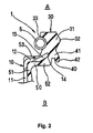
- FIG. 2 is a partially enlarged cross-sectional view of the oil seal for a valve stem of FIG. 1(1).
- An oil seal 1 for a valve stem is installed for sealing an annular space 4 between a valve guide 2 having one end facing a cam side A and the other end facing the cylinder side B, and a valve stem 3 coaxially arranged in an inner peripheral side of the valve guide 2 so as to reciprocate therein and having a valve (not shown) attached to it on the cylinder side B for performing an intaking and exhausting operation, and the oil seal 1 for a valve stem is also provided with a reinforcing ring 10 and a main seal portion 30.
- the reinforcing ring 10 is formed from a sheet metal or the like, and is composed of an axially extending portion 11 fitted to the outer peripheral side of the valve guide 2, a radially extending portion 12 extending from the end of the axially extending portion 11 on the cam side A in the radially inner direction, and an inclined portion 13 extending from the end of the radially extending portion 12 on the inner peripheral side toward the cam side A in the inclined manner.
- the fixing sealing portion 50 is formed from an inner peripheral side fixing sealing portion 51, which is fixed to the axially extending portion 11 of the reinforcing ring 10 and is brought into close contact with the outer peripheral surface of the valve guide 2, a cylinder side fixing sealing portion 52, which is fixed to the radially extending portion 12 and the inclined portion 13 on the cylinder side B and is brought into close contact with the cam side end surface 2a of the valve guide 2, and cam side fixing sealing portion 53, which is fixed to the radially extending portion 12 on the cam side A.
- the main seal portion 30 is positioned on the cam side A in relation to the radially extending portion 12 of the reinforcing ring 10, and has a main seal lip 31 and a back pressure seal lip 40, integrally formed with each other.
- the main seal lip 31 has a lip leading end portion 32 extending from the inner peripheral end 14 of the inclined portion 13 toward the cam side A, and is configured to be slidably brought into close contact with the valve stem 3, and a concave portion 33 formed on the outer peripheral side thereof, which is on the other side of the lip leading end portion 32, for installing a garter spring 5 therein for applying a tension force to the main seal lip 31 so that the same can follow a fluctuation of the valve stem 3.
- the back pressure seal lip 40 is positioned on the cam side A in relation to the radially extending portion 12, but a base portion 41 is positioned on the cylinder side B in relation to the inner peripheral end 14 of the inclined portion 13, and the lip leading end 42 extends toward the cylinder side B, and is slidably brought into close contact with the valve stem 3.
- the oil seal 1 for a valve stem constructed as described above is installed in a manner such that the axially extending portion 11 of the reinforcing ring 10 is fitted to the valve guide 2 via the inner peripheral side fixing sealing portion 51, and the main seal portion 30 having the main seal lip 31 and the back pressure seal lip 40 is slidably brought into close contact with the valve stem 3, so the main seal lip 31 can seal the lubricating oil on the cam side A from flowing out toward the cylinder side B, and allows an appropriate amount of the lubricating oil to be supplied in such an extent that a film of oil is formed in the annular space 4, and to thereby control the amount of leaking oil.
- the back pressure seal lip 40 forms the main seal portion 30 while being integrally formed with the main seal lip 31, and is disposed at a position positioned on the cam side A in relation to the radially extending portion 12 of the reinforcing ring 10, it becomes possible to shorten the length thereof in the axially extending and to reduce a size of the oil seal 1 for a valve stem. Accordingly, even in a case that the installation space is narrowed due to compact sizing of the engine, the oil seal 1 for a valve stem can be installed.
- the base portion 41 of the back pressure seal lip 40 is positioned on the cylinder side B in relation to the inner peripheral end portion 14 of the inclined portion 13, and a stress is concentrated on a portion of the back pressure seal lip 40 where the same is fixed to the inner peripheral end portion 14 of the inclined portion 13.
- a peak of the contact pressure can be brought to the lip leading end portion 42 of the back pressure seal lip 40, and a stable control for the amount of leaking oil can be performed.
Landscapes
- Engineering & Computer Science (AREA)
- General Engineering & Computer Science (AREA)
- Mechanical Engineering (AREA)
- Sealing With Elastic Sealing Lips (AREA)
Abstract
Description
- The present invention relates to an oil seal for a valve stem which is installed to a valve guide in a valve gear mechanism of an internal combustion engine.
- As an oil seal for a valve stem which is installed for sealing an annular space between a valve guide and a valve stem in a valve gear mechanism of an internal combustion engine, the following oil seals for valve stems are known. An
oil seal 100 for a valve stem, as shown in FIG. 3, is installed for sealing anannular space 104 between avalve guide 102 fixed to a through hole formed in an inner peripheral side of acylinder head 101 and having one end facing a cam side A and the other end facing a cylinder side B, and avalve stem 103 coaxially inserted in an inner peripheral side of thevalve guide 102 so as to reciprocate therein and having a valve (not shown) attached to it on the cylinder side B for performing an intaking and exhausting operation. Further, theoil seal 100 for a valve stem is provided with a reinforcingring 105 and amain seal lip 106, and is installed by fitting the reinforcingring 105 to thevalve guide 102, so lubricating oil on the cam side A is sealed from flowing out toward the cylinder side B and an appropriate amount of the lubricating oil is supplied to such an extent that a film of oil is formed in theannular space 104, to thereby control the amount of leaking oil, by allowing themain seal lip 106 to contact the peripheral surface of thevalve stem 103. - In recent years, along with a trend of providing high-power engines, the pressure in the port (cylinder side) (hereinafter, called as back pressure) tends to increase, whereby the behavior of the
main seal lip 106 becomes unstable, and in a worst case, a trouble may occur in which themain seal lip 106 may be raised from thevalve stem 103, and thereby there has been a problem that a required amount of leaking oil cannot be kept up. Therefore, as shown in FIG. 4 (1), a backpressure seal lip 108 is disposed on the cylinder side B of amain seal portion 107, separately from themain seal portion 107 having themain seal lip 106, and the back pressure is born by means of the backpressure seal lip 108, and thereby the behavior of themain seal lip 106 due to the back pressure is suppressed, and a variation of the amount of leaking oil has been intended to be suppressed. (Refer toJapanese Unexamined Patent Application Publication No. 2004-19852 - However, in the circumstances in which a compact sizing of the engines is advanced and an installation space for the
oil seal 100 for a valve stem is narrowed, if the backpressure seal lip 108 is disposed on the cylinder side B of a radially extendingportion 105a, separately from themain seal portion 107 formed on the cam side A in relation to the radially extendingportion 105a of the reinforcingring 105, theoil seal 100 for a valve stem is elongated in the axial direction and large sized, with the result that he oilseal 100 for a valve stem is not able to satisfy demands of the compact structure of the engines, and a countermeasure for that purpose is required. - As a countermeasure for the above-described situation, as shown in FIG. 5(1), it is discussed that the back
pressure seal lip 108 is integrally provided with themain seal portion 107 positioned on the cam side A of the radially extendingportion 105a. However, in the conventional structure shown in FIG. 4(1), a stress is concentrated on a portion of the backpressure seal lip 108 where the same is fixed to an innerperipheral end portion 105b of the radially extendingportion 105a when the backpressure seal lip 108 receives the back pressure, because the position of abase portion 108a of the backpressure seal lip 108 is positioned on the cylinder side B in relation to the radially extendingportion 105a of the reinforcingring 105. That is, since a deformation stress of the backpressure seal lip 108 is born by the innerperipheral end portion 105b of the radially extendingportion 105a, a peak of the contact pressure can be brought to a lip leadingend portion 108b of the backpressure seal lip 108, as shown in the contact pressure distribution in the backpressure seal lip 108 of FIG. 4(2), and it becomes possible to stably control the amount of leaking oil. On the other hand, in a structure shown in FIG. 5(1), since the backpressure seal lip 108 is integrally provided with themain seal portion 107, thebase portion 108a of the backpressure seal lip 108 is positioned on the cam side A in relation to the radially extendingportion 105a and thereby any reinforcing ring that bears the deformation stress of the backpressure seal lip 108 does not exist, and as shown in the contact pressure distribution in the back pressure seal lip of FIG. 5(2), a peak of the contact pressure cannot be brought to the lip leadingend portion 108b. Thereby, a problem in which a control of the amount of leaking oil becomes unstable is found. - In consideration of the above-described points, it is an object of the present invention to provide an oil seal for a valve stem, which can be installed to a place having a narrow installation space in an axial direction even if a back pressure seal lip is provided, can stably exclude an influence of a back pressure to a main seal lip by means of the back pressure seal lip, and can achieve a reduction of a change in the amount of leaking oil, in the oil seal for a valve stem installed to a valve guide in a valve gear mechanism of an internal combustion engine.
- In order to achieve the above-described object, an oil seal for a valve stem according to
Claim 1 with respect to the present invention is installed for sealing an annular space between a valve guide having one end facing a cam side and the other end facing a cylinder side, and a valve stem coaxially arranged in an inner peripheral side of the valve guide so as to reciprocate therein, and is characterized in that the oil seal for a valve stem is provided with a reinforcing ring fitted to the valve guide and having an inclined portion formed on an inner peripheral side of a radially extending portion and extending toward a cam side, and a main seal portion having a main seal lip slidably brought into close contact with the valve stem and extending toward the cam side, and a back pressure seal lip preventing a pressure from being applied to the main seal lip and positioned on the cylinder side in relation to the main seal lip, the main seal portion is positioned on the cam side in relation to radially extending portion, and the back pressure seal lip is positioned on the cylinder side in relation to an inner peripheral end portion of the inclined portion. - The present invention accomplishes below-described advantages. That is, in the oil seal for a valve stem according to the present invention provided with the above-described construction, since the back pressure seal lip is disposed in the main seal portion having the main seal lip positioned on the cam side in relation to the radially extending portion of the reinforcing ring, the length thereof can be shortened in the axial direction even if the back pressure seal lip is provided, and the oil seal for a valve stem can be installed to a place having a narrow installation space in which a compact sizing of the engines is advanced.
- In addition, since the inclined portion is formed on the inner peripheral side of the radially extending portion of the reinforcing ring toward the cam side, the back pressure seal lip is positioned on the cylinder side in relation to the inner peripheral end portion of the inclined portion, and a stress is concentrated on a portion where the back pressure seal lip is fixed to the inner peripheral end portion of the inclined portion. Namely, when a back pressure is exerted from the cylinder side, the deformation stress of the back pressure seal lip can be born by means of the inclined portion of the reinforcing ring, and a peak of a contact pressure can be brought to the lip leading end portion of the back pressure seal lip. Accordingly, an influence of the back pressure to the main seal lip can stably be excluded by means of the back pressure seal lip, and a stable control of the amount of leaking oil can be performed. Thus, a reduction of a change in the amount of leaking oil can be achieved.
-
- FIG. 1(1) is a cross-sectional view of a main part of an oil seal for a valve stem when installed according to the present invention;
- FIG. 1 (2) is a contact pressure distribution of a back pressure seal lip in the installed condition of FIG. 1(1);
- FIG. 2 is a partially enlarged cross-sectional view of the oil seal for a valve stem of FIG. 1(1);
- FIG. 3 is a cross-sectional view of a main part of the oil seal for a valve stem in an installed condition;
- FIG. 4(1) is a cross-sectional view of a main part of an oil seal for a valve stem when installed according to a conventional example;
- FIG. 4(2) is a contact pressure distribution of the back pressure seal lip in the installed condition of FIG. 4(1);
- FIG. 5(1) is a cross-sectional view of a main part of an oil seal for a valve stem when installed according to another conventional example; and
- FIG. 5(2) is a contact pressure distribution in the back pressure seal lip in the installed condition of FIG. 5(1).
- Hereinbelow, a preferred embodiment of the present invention will be explained with reference to the drawings by way of an example. FIG. 1(1) is a cross-sectional view showing a main part of an oil seal for a valve stem according to the present invention in an installed condition, FIG. 1 (2) is a contact pressure distribution of the back pressure seal lip in the installed condition in FIG. 1(1), and FIG. 2 is a partially enlarged cross-sectional view of the oil seal for a valve stem of FIG. 1(1).
- An
oil seal 1 for a valve stem according to the present invention is installed for sealing an annular space 4 between avalve guide 2 having one end facing a cam side A and the other end facing the cylinder side B, and a valve stem 3 coaxially arranged in an inner peripheral side of thevalve guide 2 so as to reciprocate therein and having a valve (not shown) attached to it on the cylinder side B for performing an intaking and exhausting operation, and theoil seal 1 for a valve stem is also provided with a reinforcingring 10 and amain seal portion 30. - The
reinforcing ring 10 is formed from a sheet metal or the like, and is composed of an axially extendingportion 11 fitted to the outer peripheral side of thevalve guide 2, a radially extendingportion 12 extending from the end of the axially extendingportion 11 on the cam side A in the radially inner direction, and aninclined portion 13 extending from the end of the radially extendingportion 12 on the inner peripheral side toward the cam side A in the inclined manner. - A seal
main body 20 formed from a rubber-like elastic element, which has a fixingsealing portion 50 and themain seal portion 30, integrally formed with each other, is fixed to the reinforcingring 10, as described later. Thefixing sealing portion 50 is formed from an inner peripheral sidefixing sealing portion 51, which is fixed to the axially extendingportion 11 of the reinforcingring 10 and is brought into close contact with the outer peripheral surface of thevalve guide 2, a cylinder sidefixing sealing portion 52, which is fixed to the radially extendingportion 12 and theinclined portion 13 on the cylinder side B and is brought into close contact with the cam side end surface 2a of thevalve guide 2, and cam side fixingsealing portion 53, which is fixed to the radially extendingportion 12 on the cam side A. - The
main seal portion 30 is positioned on the cam side A in relation to the radially extendingportion 12 of the reinforcingring 10, and has amain seal lip 31 and a backpressure seal lip 40, integrally formed with each other. Themain seal lip 31 has a lip leadingend portion 32 extending from the innerperipheral end 14 of theinclined portion 13 toward the cam side A, and is configured to be slidably brought into close contact with the valve stem 3, and aconcave portion 33 formed on the outer peripheral side thereof, which is on the other side of the lip leadingend portion 32, for installing a garter spring 5 therein for applying a tension force to themain seal lip 31 so that the same can follow a fluctuation of the valve stem 3. - The back
pressure seal lip 40 is positioned on the cam side A in relation to the radially extendingportion 12, but abase portion 41 is positioned on the cylinder side B in relation to the innerperipheral end 14 of theinclined portion 13, and thelip leading end 42 extends toward the cylinder side B, and is slidably brought into close contact with the valve stem 3. - The
oil seal 1 for a valve stem constructed as described above is installed in a manner such that the axially extendingportion 11 of thereinforcing ring 10 is fitted to thevalve guide 2 via the inner peripheral sidefixing sealing portion 51, and themain seal portion 30 having themain seal lip 31 and the backpressure seal lip 40 is slidably brought into close contact with the valve stem 3, so themain seal lip 31 can seal the lubricating oil on the cam side A from flowing out toward the cylinder side B, and allows an appropriate amount of the lubricating oil to be supplied in such an extent that a film of oil is formed in the annular space 4, and to thereby control the amount of leaking oil. - In this case, since the back
pressure seal lip 40 forms themain seal portion 30 while being integrally formed with themain seal lip 31, and is disposed at a position positioned on the cam side A in relation to the radially extendingportion 12 of the reinforcingring 10, it becomes possible to shorten the length thereof in the axially extending and to reduce a size of theoil seal 1 for a valve stem. Accordingly, even in a case that the installation space is narrowed due to compact sizing of the engine, theoil seal 1 for a valve stem can be installed. - Furthermore, since the
inclined portion 13 is formed on the inner peripheral side of the radially extendingportion 12 of thereinforcing ring 10 toward the cam side A, thebase portion 41 of the backpressure seal lip 40 is positioned on the cylinder side B in relation to the innerperipheral end portion 14 of theinclined portion 13, and a stress is concentrated on a portion of the backpressure seal lip 40 where the same is fixed to the innerperipheral end portion 14 of theinclined portion 13. In other word, it becomes possible to bear a deformation stress of the backpressure seal lip 40 by means of the innerperipheral end portion 14 of theinclined portion 13 of the reinforcingring 10 when a back pressure is applied from the cylinder side B. Furthermore, as shown in the contact pressure distribution of the backpressure seal lip 40 in FIG. 1(2), a peak of the contact pressure can be brought to the lip leadingend portion 42 of the backpressure seal lip 40, and a stable control for the amount of leaking oil can be performed.
Claims (6)
- An oil seal (1) for a valve stem, comprising a main seal portion (30) having a cam side (A), a cylinder side (B), a main seal lip (31) extending toward the cam side (A) and a back pressure seal lip (40) positioned on cylinder side (B) in relation to the main seal lip (31) for preventing a pressure from being applied to the main seal lip (31), and a reinforcing ring (10) having an inclined portion (13) formed on an inner peripheral side of a radially extending portion (12).
- An oil seal according to claim 1, characterized in that the inclined portion (13) extends from the end of the radially extending portion (12) toward the cam side (A) in the inclined manner.
- An oil seal according to claim 1 or 2, characterized in that the back pressure seal lip (40) is positioned on the cam side (A) in relation to the radially extending portion (12).
- An oil seal according to one of the claims 1 to 3, characterized in that the back pressure seal lip (40) has a base portion (41) and a lip leading end (42), whereas the base portion (41) is positioned on the cylinder side (B) in relation to an inner peripheral end (14) of the inclined portion (13) and the lip leading end (42) extends toward the cylinder side (B).
- An oil seal according to one of the claims 1 to 4, characterized in that the back pressure seal lip (40) forms the main seal portion (30) being integrally formed with the main seal lip (31).
- An assembly comprising a valve stem (3), a valve guide (2) and an oil seal (1) according to one of the preceding claims installed for sealing an annular space (4) between the valve guide (2) having one end facing a cam side (A) and the other end facing a cylinder side (B), and the valve stem (3) coaxially arranged in an inner peripheral side of the valve guide (2) so as to reciprocate therein, whereas the oil seal (1) for a valve stem (3) is provided with a reinforcing ring (10) fitted to the valve guide (3) and having an inclined portion (13) formed on an inner peripheral side of a radially extending portion (12) and extending toward a cam side (A), and a main seal portion (30) having a main seal lip (31) slidably brought into close contact with the valve stem (3) and extending toward the cam side (A), and a back pressure seal lip (40) preventing a pressure from being applied to the main seal lip (31) and positioned on the cylinder side (B) in relation to the main seal lip (31), the main seal portion (30) is positioned on the cam side (A) in relation to the radially extending portion (12), and the back pressure seal lip (40) is positioned on the cylinder side (B) in relation to an inner peripheral end portion of the inclined portion (13).
Applications Claiming Priority (1)
| Application Number | Priority Date | Filing Date | Title |
|---|---|---|---|
| JP2006221417A JP2008045654A (en) | 2006-08-15 | 2006-08-15 | Oil seal for valve stem |
Publications (2)
| Publication Number | Publication Date |
|---|---|
| EP1890058A1 true EP1890058A1 (en) | 2008-02-20 |
| EP1890058B1 EP1890058B1 (en) | 2018-07-25 |
Family
ID=38510320
Family Applications (1)
| Application Number | Title | Priority Date | Filing Date |
|---|---|---|---|
| EP07015776.3A Active EP1890058B1 (en) | 2006-08-15 | 2007-08-10 | Oil seal for valve stem |
Country Status (4)
| Country | Link |
|---|---|
| EP (1) | EP1890058B1 (en) |
| JP (1) | JP2008045654A (en) |
| ES (1) | ES2687042T3 (en) |
| HU (1) | HUE041547T2 (en) |
Cited By (2)
| Publication number | Priority date | Publication date | Assignee | Title |
|---|---|---|---|---|
| WO2014200967A1 (en) * | 2013-06-10 | 2014-12-18 | Fisher Controls International Llc | Actuator bushings having integral seals |
| EP3967856A1 (en) | 2020-09-11 | 2022-03-16 | Freudenberg Sealing Technologies S.A.S. Di Externa Italia S.r.l.u. | Gasket for a valve of an internal combustion engine |
Families Citing this family (2)
| Publication number | Priority date | Publication date | Assignee | Title |
|---|---|---|---|---|
| ITTO20131018A1 (en) | 2013-12-13 | 2015-06-14 | Corcos Ind S A S Di Extern A Italia S R L | GASKET FOR A SINGLE COMBUSTION ENGINE VALVE |
| JP6534550B2 (en) * | 2015-04-01 | 2019-06-26 | Nok株式会社 | Valve stem seal |
Citations (1)
| Publication number | Priority date | Publication date | Assignee | Title |
|---|---|---|---|---|
| JP2000329234A (en) * | 1999-05-18 | 2000-11-30 | Nok Corp | Valve stem seal |
Family Cites Families (4)
| Publication number | Priority date | Publication date | Assignee | Title |
|---|---|---|---|---|
| JP2002071029A (en) * | 2000-08-28 | 2002-03-08 | Nok Corp | Sealing device |
| JP2002139156A (en) * | 2000-11-02 | 2002-05-17 | Nok Corp | Rotary body oil seal |
| US6729624B1 (en) * | 2001-02-20 | 2004-05-04 | Freudenberg-Nok General Partnership | Radial shaft seal |
| JP2004176881A (en) * | 2002-11-29 | 2004-06-24 | Nok Corp | Sealing device |
-
2006
- 2006-08-15 JP JP2006221417A patent/JP2008045654A/en active Pending
-
2007
- 2007-08-10 EP EP07015776.3A patent/EP1890058B1/en active Active
- 2007-08-10 ES ES07015776.3T patent/ES2687042T3/en active Active
- 2007-08-10 HU HUE07015776A patent/HUE041547T2/en unknown
Patent Citations (1)
| Publication number | Priority date | Publication date | Assignee | Title |
|---|---|---|---|---|
| JP2000329234A (en) * | 1999-05-18 | 2000-11-30 | Nok Corp | Valve stem seal |
Cited By (3)
| Publication number | Priority date | Publication date | Assignee | Title |
|---|---|---|---|---|
| WO2014200967A1 (en) * | 2013-06-10 | 2014-12-18 | Fisher Controls International Llc | Actuator bushings having integral seals |
| US10260639B2 (en) | 2013-06-10 | 2019-04-16 | Fisher Controls International Llc | Actuator bushings having integral seals |
| EP3967856A1 (en) | 2020-09-11 | 2022-03-16 | Freudenberg Sealing Technologies S.A.S. Di Externa Italia S.r.l.u. | Gasket for a valve of an internal combustion engine |
Also Published As
| Publication number | Publication date |
|---|---|
| JP2008045654A (en) | 2008-02-28 |
| ES2687042T3 (en) | 2018-10-23 |
| EP1890058B1 (en) | 2018-07-25 |
| HUE041547T2 (en) | 2019-05-28 |
Similar Documents
| Publication | Publication Date | Title |
|---|---|---|
| EP1884630A1 (en) | Valve stem seal | |
| EP1959142B1 (en) | Plunger seal for pump | |
| EP2093455B1 (en) | Magnetorheological (MR) rod guide assembly and MR damper having same | |
| KR20020087491A (en) | Sealing device a fuel injection valve | |
| EP1959172A1 (en) | Lip type seal | |
| US7862048B2 (en) | Gasket for a valve in an internal combustion engine | |
| US20090145393A1 (en) | Valve Stem Seal With Gas Relief Features | |
| EP1890058B1 (en) | Oil seal for valve stem | |
| EP1854965A1 (en) | Oil seal | |
| US8011669B2 (en) | Valve stem seal with gas relief features | |
| US8764019B2 (en) | Gasket for a valve in an internal combustion engine | |
| WO2017030060A1 (en) | Valve stem seal and sealing structure | |
| EP1818514A1 (en) | Sealing apparatus | |
| EP1749980B1 (en) | Gasket for a valve of an internal combustion engine | |
| EP0566059B1 (en) | Seal for a rod sliding against the action of elastic means, in particular an internal combustion engine valve stem | |
| JP3824697B2 (en) | Reciprocating sealing device | |
| EP2241730A1 (en) | Valve stem seal with gas relief features | |
| JP4734712B2 (en) | Valve stem seal | |
| CN110914579A (en) | Valve stem seal | |
| US10746062B2 (en) | Gasket with an improved heat dissipation capacity for a valve of an internal combustion engine | |
| JPH10205623A (en) | Valve stem seal | |
| JP2016223558A (en) | Sealing structure | |
| JP2007024205A (en) | Oil seal | |
| JP7752785B2 (en) | Valve stem seal sealing device | |
| JP2019044898A (en) | Valve stem seal |
Legal Events
| Date | Code | Title | Description |
|---|---|---|---|
| PUAI | Public reference made under article 153(3) epc to a published international application that has entered the european phase |
Free format text: ORIGINAL CODE: 0009012 |
|
| AK | Designated contracting states |
Kind code of ref document: A1 Designated state(s): AT BE BG CH CY CZ DE DK EE ES FI FR GB GR HU IE IS IT LI LT LU LV MC MT NL PL PT RO SE SI SK TR |
|
| AX | Request for extension of the european patent |
Extension state: AL BA HR MK YU |
|
| 17P | Request for examination filed |
Effective date: 20080509 |
|
| AKX | Designation fees paid |
Designated state(s): AT BE BG CH CY CZ DE DK EE ES FI FR GB GR HU IE IS IT LI LT LU LV MC MT NL PL PT RO SE SI SK TR |
|
| 17Q | First examination report despatched |
Effective date: 20150615 |
|
| REG | Reference to a national code |
Ref country code: DE Ref legal event code: R079 Ref document number: 602007055484 Country of ref document: DE Free format text: PREVIOUS MAIN CLASS: F16J0015320000 Ipc: F16K0041080000 |
|
| GRAP | Despatch of communication of intention to grant a patent |
Free format text: ORIGINAL CODE: EPIDOSNIGR1 |
|
| RIC1 | Information provided on ipc code assigned before grant |
Ipc: F01L 3/08 20060101ALN20180323BHEP Ipc: F16J 15/32 20060101ALN20180323BHEP Ipc: F16K 41/08 20060101AFI20180323BHEP Ipc: F16L 3/08 20060101ALI20180323BHEP |
|
| RIC1 | Information provided on ipc code assigned before grant |
Ipc: F16J 15/32 20060101ALN20180405BHEP Ipc: F16L 3/08 20060101ALI20180405BHEP Ipc: F16K 41/08 20060101AFI20180405BHEP Ipc: F01L 3/08 20060101ALN20180405BHEP |
|
| INTG | Intention to grant announced |
Effective date: 20180420 |
|
| GRAS | Grant fee paid |
Free format text: ORIGINAL CODE: EPIDOSNIGR3 |
|
| GRAA | (expected) grant |
Free format text: ORIGINAL CODE: 0009210 |
|
| AK | Designated contracting states |
Kind code of ref document: B1 Designated state(s): AT BE BG CH CY CZ DE DK EE ES FI FR GB GR HU IE IS IT LI LT LU LV MC MT NL PL PT RO SE SI SK TR |
|
| REG | Reference to a national code |
Ref country code: GB Ref legal event code: FG4D |
|
| REG | Reference to a national code |
Ref country code: CH Ref legal event code: EP |
|
| REG | Reference to a national code |
Ref country code: AT Ref legal event code: REF Ref document number: 1022135 Country of ref document: AT Kind code of ref document: T Effective date: 20180815 |
|
| REG | Reference to a national code |
Ref country code: DE Ref legal event code: R096 Ref document number: 602007055484 Country of ref document: DE |
|
| REG | Reference to a national code |
Ref country code: IE Ref legal event code: FG4D |
|
| REG | Reference to a national code |
Ref country code: FR Ref legal event code: PLFP Year of fee payment: 12 |
|
| REG | Reference to a national code |
Ref country code: ES Ref legal event code: FG2A Ref document number: 2687042 Country of ref document: ES Kind code of ref document: T3 Effective date: 20181023 |
|
| REG | Reference to a national code |
Ref country code: NL Ref legal event code: MP Effective date: 20180725 |
|
| REG | Reference to a national code |
Ref country code: LT Ref legal event code: MG4D |
|
| PG25 | Lapsed in a contracting state [announced via postgrant information from national office to epo] |
Ref country code: NL Free format text: LAPSE BECAUSE OF FAILURE TO SUBMIT A TRANSLATION OF THE DESCRIPTION OR TO PAY THE FEE WITHIN THE PRESCRIBED TIME-LIMIT Effective date: 20180725 |
|
| REG | Reference to a national code |
Ref country code: AT Ref legal event code: MK05 Ref document number: 1022135 Country of ref document: AT Kind code of ref document: T Effective date: 20180725 |
|
| PG25 | Lapsed in a contracting state [announced via postgrant information from national office to epo] |
Ref country code: GR Free format text: LAPSE BECAUSE OF FAILURE TO SUBMIT A TRANSLATION OF THE DESCRIPTION OR TO PAY THE FEE WITHIN THE PRESCRIBED TIME-LIMIT Effective date: 20181026 Ref country code: BG Free format text: LAPSE BECAUSE OF FAILURE TO SUBMIT A TRANSLATION OF THE DESCRIPTION OR TO PAY THE FEE WITHIN THE PRESCRIBED TIME-LIMIT Effective date: 20181025 Ref country code: SE Free format text: LAPSE BECAUSE OF FAILURE TO SUBMIT A TRANSLATION OF THE DESCRIPTION OR TO PAY THE FEE WITHIN THE PRESCRIBED TIME-LIMIT Effective date: 20180725 Ref country code: LT Free format text: LAPSE BECAUSE OF FAILURE TO SUBMIT A TRANSLATION OF THE DESCRIPTION OR TO PAY THE FEE WITHIN THE PRESCRIBED TIME-LIMIT Effective date: 20180725 Ref country code: IS Free format text: LAPSE BECAUSE OF FAILURE TO SUBMIT A TRANSLATION OF THE DESCRIPTION OR TO PAY THE FEE WITHIN THE PRESCRIBED TIME-LIMIT Effective date: 20181125 Ref country code: AT Free format text: LAPSE BECAUSE OF FAILURE TO SUBMIT A TRANSLATION OF THE DESCRIPTION OR TO PAY THE FEE WITHIN THE PRESCRIBED TIME-LIMIT Effective date: 20180725 Ref country code: FI Free format text: LAPSE BECAUSE OF FAILURE TO SUBMIT A TRANSLATION OF THE DESCRIPTION OR TO PAY THE FEE WITHIN THE PRESCRIBED TIME-LIMIT Effective date: 20180725 Ref country code: PL Free format text: LAPSE BECAUSE OF FAILURE TO SUBMIT A TRANSLATION OF THE DESCRIPTION OR TO PAY THE FEE WITHIN THE PRESCRIBED TIME-LIMIT Effective date: 20180725 |
|
| PG25 | Lapsed in a contracting state [announced via postgrant information from national office to epo] |
Ref country code: LV Free format text: LAPSE BECAUSE OF FAILURE TO SUBMIT A TRANSLATION OF THE DESCRIPTION OR TO PAY THE FEE WITHIN THE PRESCRIBED TIME-LIMIT Effective date: 20180725 |
|
| REG | Reference to a national code |
Ref country code: CH Ref legal event code: PL |
|
| REG | Reference to a national code |
Ref country code: DE Ref legal event code: R097 Ref document number: 602007055484 Country of ref document: DE |
|
| PG25 | Lapsed in a contracting state [announced via postgrant information from national office to epo] |
Ref country code: EE Free format text: LAPSE BECAUSE OF FAILURE TO SUBMIT A TRANSLATION OF THE DESCRIPTION OR TO PAY THE FEE WITHIN THE PRESCRIBED TIME-LIMIT Effective date: 20180725 Ref country code: MC Free format text: LAPSE BECAUSE OF FAILURE TO SUBMIT A TRANSLATION OF THE DESCRIPTION OR TO PAY THE FEE WITHIN THE PRESCRIBED TIME-LIMIT Effective date: 20180725 Ref country code: RO Free format text: LAPSE BECAUSE OF FAILURE TO SUBMIT A TRANSLATION OF THE DESCRIPTION OR TO PAY THE FEE WITHIN THE PRESCRIBED TIME-LIMIT Effective date: 20180725 Ref country code: LI Free format text: LAPSE BECAUSE OF NON-PAYMENT OF DUE FEES Effective date: 20180831 Ref country code: CZ Free format text: LAPSE BECAUSE OF FAILURE TO SUBMIT A TRANSLATION OF THE DESCRIPTION OR TO PAY THE FEE WITHIN THE PRESCRIBED TIME-LIMIT Effective date: 20180725 Ref country code: LU Free format text: LAPSE BECAUSE OF NON-PAYMENT OF DUE FEES Effective date: 20180810 Ref country code: CH Free format text: LAPSE BECAUSE OF NON-PAYMENT OF DUE FEES Effective date: 20180831 |
|
| REG | Reference to a national code |
Ref country code: BE Ref legal event code: MM Effective date: 20180831 |
|
| REG | Reference to a national code |
Ref country code: HU Ref legal event code: AG4A Ref document number: E041547 Country of ref document: HU |
|
| REG | Reference to a national code |
Ref country code: IE Ref legal event code: MM4A |
|
| PG25 | Lapsed in a contracting state [announced via postgrant information from national office to epo] |
Ref country code: DK Free format text: LAPSE BECAUSE OF FAILURE TO SUBMIT A TRANSLATION OF THE DESCRIPTION OR TO PAY THE FEE WITHIN THE PRESCRIBED TIME-LIMIT Effective date: 20180725 Ref country code: SK Free format text: LAPSE BECAUSE OF FAILURE TO SUBMIT A TRANSLATION OF THE DESCRIPTION OR TO PAY THE FEE WITHIN THE PRESCRIBED TIME-LIMIT Effective date: 20180725 |
|
| PLBE | No opposition filed within time limit |
Free format text: ORIGINAL CODE: 0009261 |
|
| STAA | Information on the status of an ep patent application or granted ep patent |
Free format text: STATUS: NO OPPOSITION FILED WITHIN TIME LIMIT |
|
| 26N | No opposition filed |
Effective date: 20190426 |
|
| PG25 | Lapsed in a contracting state [announced via postgrant information from national office to epo] |
Ref country code: IE Free format text: LAPSE BECAUSE OF NON-PAYMENT OF DUE FEES Effective date: 20180810 |
|
| PG25 | Lapsed in a contracting state [announced via postgrant information from national office to epo] |
Ref country code: BE Free format text: LAPSE BECAUSE OF NON-PAYMENT OF DUE FEES Effective date: 20180831 Ref country code: SI Free format text: LAPSE BECAUSE OF FAILURE TO SUBMIT A TRANSLATION OF THE DESCRIPTION OR TO PAY THE FEE WITHIN THE PRESCRIBED TIME-LIMIT Effective date: 20180725 |
|
| PG25 | Lapsed in a contracting state [announced via postgrant information from national office to epo] |
Ref country code: MT Free format text: LAPSE BECAUSE OF NON-PAYMENT OF DUE FEES Effective date: 20180810 |
|
| PG25 | Lapsed in a contracting state [announced via postgrant information from national office to epo] |
Ref country code: TR Free format text: LAPSE BECAUSE OF FAILURE TO SUBMIT A TRANSLATION OF THE DESCRIPTION OR TO PAY THE FEE WITHIN THE PRESCRIBED TIME-LIMIT Effective date: 20180725 |
|
| PG25 | Lapsed in a contracting state [announced via postgrant information from national office to epo] |
Ref country code: PT Free format text: LAPSE BECAUSE OF FAILURE TO SUBMIT A TRANSLATION OF THE DESCRIPTION OR TO PAY THE FEE WITHIN THE PRESCRIBED TIME-LIMIT Effective date: 20180725 |
|
| PG25 | Lapsed in a contracting state [announced via postgrant information from national office to epo] |
Ref country code: CY Free format text: LAPSE BECAUSE OF FAILURE TO SUBMIT A TRANSLATION OF THE DESCRIPTION OR TO PAY THE FEE WITHIN THE PRESCRIBED TIME-LIMIT Effective date: 20180725 |
|
| P01 | Opt-out of the competence of the unified patent court (upc) registered |
Effective date: 20230606 |
|
| PGFP | Annual fee paid to national office [announced via postgrant information from national office to epo] |
Ref country code: HU Payment date: 20250731 Year of fee payment: 19 |
|
| PGFP | Annual fee paid to national office [announced via postgrant information from national office to epo] |
Ref country code: ES Payment date: 20250916 Year of fee payment: 19 |
|
| PGFP | Annual fee paid to national office [announced via postgrant information from national office to epo] |
Ref country code: DE Payment date: 20250827 Year of fee payment: 19 |
|
| PGFP | Annual fee paid to national office [announced via postgrant information from national office to epo] |
Ref country code: IT Payment date: 20250825 Year of fee payment: 19 |
|
| PGFP | Annual fee paid to national office [announced via postgrant information from national office to epo] |
Ref country code: GB Payment date: 20250826 Year of fee payment: 19 |
|
| PGFP | Annual fee paid to national office [announced via postgrant information from national office to epo] |
Ref country code: FR Payment date: 20250825 Year of fee payment: 19 |