EP1889957A1 - Full rotary hook - Google Patents
Full rotary hook Download PDFInfo
- Publication number
- EP1889957A1 EP1889957A1 EP07015968A EP07015968A EP1889957A1 EP 1889957 A1 EP1889957 A1 EP 1889957A1 EP 07015968 A EP07015968 A EP 07015968A EP 07015968 A EP07015968 A EP 07015968A EP 1889957 A1 EP1889957 A1 EP 1889957A1
- Authority
- EP
- European Patent Office
- Prior art keywords
- needle
- beak
- needle guide
- hook
- sewing
- Prior art date
- Legal status (The legal status is an assumption and is not a legal conclusion. Google has not performed a legal analysis and makes no representation as to the accuracy of the status listed.)
- Granted
Links
- 238000009958 sewing Methods 0.000 claims abstract description 108
- 210000003323 beak Anatomy 0.000 claims abstract description 80
- 230000007246 mechanism Effects 0.000 claims abstract description 24
- 230000008878 coupling Effects 0.000 claims description 39
- 238000010168 coupling process Methods 0.000 claims description 39
- 238000005859 coupling reaction Methods 0.000 claims description 39
- 230000003068 static effect Effects 0.000 description 4
- 239000004744 fabric Substances 0.000 description 3
- 230000004048 modification Effects 0.000 description 2
- 238000012986 modification Methods 0.000 description 2
- 238000005452 bending Methods 0.000 description 1
- 230000005540 biological transmission Effects 0.000 description 1
- 230000008859 change Effects 0.000 description 1
- 230000003028 elevating effect Effects 0.000 description 1
- 239000000463 material Substances 0.000 description 1
- 230000010355 oscillation Effects 0.000 description 1
- 230000000149 penetrating effect Effects 0.000 description 1
Images



Classifications
-
- D—TEXTILES; PAPER
- D05—SEWING; EMBROIDERING; TUFTING
- D05B—SEWING
- D05B57/00—Loop takers, e.g. loopers
- D05B57/26—Bobbin holders or casings; Bobbin holder or case guards; Bobbin discharge devices
-
- D—TEXTILES; PAPER
- D05—SEWING; EMBROIDERING; TUFTING
- D05B—SEWING
- D05B55/00—Needle holders; Needle bars
- D05B55/06—Needle guides; Needle protectors
-
- D—TEXTILES; PAPER
- D05—SEWING; EMBROIDERING; TUFTING
- D05B—SEWING
- D05B57/00—Loop takers, e.g. loopers
- D05B57/08—Loop takers, e.g. loopers for lock-stitch sewing machines
-
- D—TEXTILES; PAPER
- D05—SEWING; EMBROIDERING; TUFTING
- D05B—SEWING
- D05B57/00—Loop takers, e.g. loopers
- D05B57/08—Loop takers, e.g. loopers for lock-stitch sewing machines
- D05B57/10—Shuttles
- D05B57/14—Shuttles with rotary hooks
Definitions
- the present disclosure is directed to a full rotary hook unit having a needle guide element provided in an outer hook of a full rotary hook rotating in synchronization with vertical movement of a sewing needle, which needle guide element allows adjustment of clearance between a beak and the sewing needle.
- the vertical full rotary hook includes an outer hook provided rotatably about a horizontal rotational shaft, a middle hook supported rotatably by the outer hook, and a bobbin case attached to the middle hook.
- JP S57-13017 Y discloses a needle guide mechanism for a full rotary hook of a sewing machine in which a substantially semicircular needle guide plate (presser plate) is screw fastened from the rear side of the outer hook.
- a portion of the needle guide plate is curved in L-shape in side view, whereby a needle groove and a static needle guide element are formed.
- the needle guide plate has a circumferential adjustable needle guide element secured thereto by an adjustable screw.
- the sewing needle can be moved in close proximity of the beak by tightening the adjustment screw and reducing the clearance between the adjustable needle guide element and the static needle guide element.
- the sewing needle can be moved away from the beak by loosening the adjustment screw and increasing the clearance between the adjustable needle guide element and the static needle guide element.
- the needle guide mechanism for a full rotary hook of a sewing machine described in reference document 1 allows the adjustment screw to be manually tightened and loosened depending on the thickness of the sewing needle to be used.
- excessive tightening of the adjustment screw results in insufficient clearance between the adjustable needle guide element and the static needle guide element, in which state the descending sewing needle collides with the rotating beak, leading to bending and damaging of the sewing needle.
- a hook shaft of the full rotary hook and the lower shaft are connected by a coupling element disposed in the immediate rear side of the full rotary hook.
- the needle guide plate is screw fastened from the rear side of the outer hook and the adjustment screw is mounted on the rear side (coupling element side) of the needle guide plate.
- An object of the present disclosure is to provide a full rotational hook unit capable of easily adjusting the clearance between the sewing needle and the beak when using sewing needles of different thickness.
- a full rotary hook unit of the present disclosure is provided below a needle plate of a sewing machine and includes an outer hook having a beak rotating integrally with a lower shaft in synchronization with a vertical movement of a sewing needle, and a middle hook rotatably supported by the outer hook, the full rotary hook characterized by a needle guide element that is formed independent of the outer hook and the middle hook, and that guides the sewing needle at least for a predetermined time period immediately before the beak encounters the sewing needle to adjust clearance between the sewing needle and the beak; and a position adjustment mechanism that mounts the needle guide element on the outer hook or an element rotating integrally with the outer hook so as to allow adjustment of the needle guide element in a axial direction of the lower shaft.
- the user when the user changes the sewing needle to a sewing needle of different thickness, the user is allowed to adjust the positioning of the needle guide element in the axial direction of the lower shaft by the position adjustment mechanism.
- the clearance between the sewing needle and the beak can be readily adjusted since the needle guide plate rearwardly guides the sewing needle at least for a predetermined time period immediately before the beak encounters the sewing needle.
- the element rotating integrally with the outer hook may be a coupling element connecting the lower shaft and the outer hook. According to such configuration, no additional parts are required for attachment of the position adjustment mechanism.
- a needle guide portion in plate-form that confronts the sewing needle may be provided in the needle guide element and a proximal end relative to the beak of the needle guide portion may be configured to be higher than the distal end relative to the beak.
- lowering the height of the needle guide reduces the area of contact between the sewing needle and the needle guide portion.
- lowering the height disables the guidance of the sewing needle due to the elevation of the sewing needle.
- the sewing needle can be guided reliably by increasing the height at the proximal end relative to the beak of the needle guide portion.
- the proximal end relative to the beak of the needle guide portion may be situated in substantially the same position as the beak in the axial direction of the lower shaft and the distal end relative to the beak may be situated in the middle hook side relative to the beak in the axial direction of the lower shaft.
- the sewing needle can be guided gradually to the position substantially the same as the beak in the axial direction of the lower shaft (which is a desirable position for the beak to seize the needle thread) by being moved along from the distal end relative to the beak of the needle guide portion to the proximal end relative to the beak of the needle guide portion.
- the sewing needle When the sewing needle is situated in the proximity of distal end relative to the beak of the needle guide portion, the sewing needle can be easily moved along the needle guide portion since marginal space can be secured between the sewing needle and the needle guide portion.
- a presser plate having a notch is provided integrally with the rear side of the outer hook, and the needle guide portion may be passed through the notch from the rear side.
- Such configuration renders a compact needle guide element.
- the position adjustment mechanism may be provided with a connection mechanism capable of connecting and disconnecting a securing portion defined in the needle guide element and the coupling element.
- the securing portion formed in the needle guide element and the coupling element may be disconnected to change the positioning of the needle guide element relative to the coupling element. Thereafter, the needle guide element can be secured to the coupling element at the changed position.
- connection mechanism may establish its connection by an long hole defined in the securing portion and formed in the axial direction of the lower shaft, a screw passed through the long hole, and a screw hole defined in the coupling element.
- the user When using a sewing needle of different thickness, the user is allowed to readily adjust the positioning of the securing portion in the axial direction of the lower shaft which is the direction in which the long hole is oriented.
- the workability of tightening and loosening of the screw can be improved since the screw is screwed into the screw hole of the coupling element.
- a cut is defined in the coupling element by cutting along the axial direction of the lower shaft, and the connection mechanism may secure the securing portion to the cut by a screw so as to allow adjustment of the securing portion in the axial direction.
- the screw can be readily tightened and loosened from the lateral direction of the coupling element.
- the needle guide element may guide the sewing needle in a predetermined time period immediately after the beak has encountered the sewing needle in addition to the predetermined time period immediately before the beak encounters the sewing needle.
- a vertical full rotary hook unit of the present embodiment is provided with a vertical full rotary hook 10, a lower shaft 4, and a coupling element 5 connecting the lower shaft 4 and the vertical full rotary hook 10.
- the vertical full rotary hook 10 is provided below a needle plate 1 of a pattern sewing machine (not shown).
- the vertical full rotary hook 10 is provided with an outer hook 11 rotated by the lower shaft 4, a middle hook 12 rotatably supported by the outer hook 11, and a loop presser plate 13 provided integrally with the rear side of the.outer hook 11.
- the outer hook 11 is provided with an outer hook body 14 and a hook shaft 15 connecting to the outer hook body 14. Rotational force of the lower shaft 4 rotating in synchronization with a main shaft (not shown) is transmitted to the hook shaft 15 via the coupling element 5. Thus, the outer hook 11 and the coupling element 5 are rotated integrally. Transmission of rotational force to the hook shaft 15 causes the outer hook 11 to be rotated clockwise in front view (assuming that the left side of FIG.1 and the lower side of FIG.3 indicate the front direction respectively) about the hook shaft 15 in synchronization with the vertical movement of the sewing needle 3.
- the outer hook body 14 has a beak 11a formed thereto which is directed toward the clockwise rotational direction.
- the middle hook 12 is provided with a middle hook body 17 and a shaft 18, and is fitted co-axially with the outer hook body 14.
- the middle hook 12 and the outer hook 14 support each other rotatably.
- the shaft 18 is provided so as to project from the bottom of the middle hook body 17 to the opened end side of the middle hook body 17 and supports a bobbin case (not shown) that contains a bobbin (not shown) in a rotatable manner.
- the lower shaft 4 is supported rotatably to the bed frame (not shown) by a bearing 6.
- the outer hook 11 When rotational force is transmitted to the vertical full rotary hook 10 by the rotation of the lower shaft 4, the outer hook 11 is rotated clockwise in front view in synchronization with the vertical movement of the sewing needle 3, with the middle hook 12 and the bobbin case in unrotatable state.
- the rotation of the outer hook 11 causes a needle thread (not shown) extending from an eye 3a of the sewing needle 3 penetrating the workpiece cloth to be seized by the beak 11a and carried around the middle hook 12.
- the needle thread extending from the eye 3a of the sewing needle 3 is intertwined with the bobbin thread (not shown) extending from the bobbin. Thereafter, the needle thread loop is tightened by a thread take-up (not shown) to form a stitch.
- the loop presser plate 13 is composed of a plate element taking a substantially semicircular form that surrounds the lower shaft 4 and is secured to the rear side of the outer hook 11 by a fastening screw 19 from the coupling element 5 side (rear side).
- a needle passage S allowing passage of the sewing needle 3 is defined between the rear surface of the outer hook 11 and the loop presser plate 13.
- the loop presser plate 13 has a notch 13a in predetermined width defined thereto.
- the notch 13a confronts the distal end of the sewing needle 3 during the time period in which the outer hook 11 rotates from a position immediately before the lowermost rotational position (rotational position of the outer hook 11 in which the sewing needle 3 is in a position immediately before the lowermost position) to a post-encounter rotational position (rotational position immediately after the beak 11a encounters the sewing needle 3).
- the needle guide plate 20 takes a stepped form in side view .(assuming that the left side in FIG.4 indicates the front side) made of plate material, and a securing portion 20a oriented in the longitudinal direction is formed integrally with the right end of the thread guide plate 20.
- a needle guide portion 20c is formed in the upper front end portion of the needle guide plate 20.
- the lateral width of the thread guide portion 20c is configured slightly narrower than the notch 13a of the loop presser plate 13.
- the securing portion 20a has a longitudinally long hole 20b defined thereto.
- the height of the needle guide portion 20c is formed in a substantially curved profile such that distal end relative to the beak 11a is lower than the proximal end relative to the beak 11a.
- the needle guide plate 20 guides the distal end (lower end) of the sewing needle 3 during a predetermined time period (at least the sum of the predetermined time period immediately before the beak 11a encounters the sewing needle 3 and the predetermined time period immediately after the sewing needle 3 encounters the beak 11a) in which the sewing needle 3 in the lowermost position (refer to FIG. 5) is elevated (refer to FIG.2) to the position immediately after encountering the beak 11a (refer to FIG.6) .
- the rotational angle taken by the outer hook 11 until the beak 11a encounters the sewing needle 3 is approximately 50 degrees.
- the needle guide plate 20 is formed so as to be sloped relative to the plane perpendicular to the axial direction of the lower shaft 4. As illustrated in FIGS.3 and 4, the distal end relative to the beak 11a of the needle guide portion 20c is positioned in the middle hook 12 side (front side) relative to the beak 11a in the axial direction of the lower shaft 4. The proximal end relative to the beak 11a of the needle guide portion 20c is positioned in substantially the same position as the beak 11a in the axial direction of the lower shaft 4. As illustrated in FIGS. 1 and 2, the needle guide portion 20c is positioned in the needle passage S by passing through the notch 13a of the loop presser plate 13 from the rear side.
- the proximal end relative to the beak 11a of the needle guide portion 20c being positioned in substantially the same position as the beak 11a denotes that the proximal end relative to the beak 11a may be positioned slightly in the middle hook 12 side (front side) relative to the beak 11a and that the proximal end relative to the beak 11a may be positioned slightly in the lower shaft 4 side (rear side) relative to the beak 11a.
- the position adjustment mechanism 22 is mounted on the coupling element 5 so that its positioning is adjustable in the longitudinal direction (axial direction of the lower shaft 4) within the needle passage S.
- an orthogonal cut 5a is defined along the shaft direction (longitudinal direction) of the lower shaft 4 in a portion slightly in the right side of the upper end of the coupling element 5.
- the securing portion 20a of the needle guide plate 20 assumes a vertical disposition and is arranged in the longitudinal direction along the vertical wall of the cut 5a.
- the needle guide plate 20 is mounted on the coupling element 5 so as to allow adjustment in its longitudinal positioning relative to the coupling element 5 by screwing the fastening screw 23 inserted in the long hole 20b into the vertical wall of the cut 5a.
- the securing portion 20a, the long hole 20b, the fastening screw 23, and the screw hole 25 of the coupling element 5 constitute the connection mechanism allowing connection and disconnection of the securing portion 20a formed in the needle guide plate 20 and the coupling element 5.
- the angle in which the cut 5a is cut off is not limited to 90 degrees.
- the user Before starting a sewing operation, the user is to attach a sewing needle 3 which is suitable for the thickness and the type of workpeice cloth to be sewn on the needle bar 2. Then, a hand pulley (not shown) of the pattern sewing machine is manually operated to lower the sewing needle 3 to a state immediately after encountering the beak 11a (refer to FIG.6). Under such state, the fastening screw 23 is loosened with a tool and positioning of the needle guide plate 20 is adjusted so as to provide a predetermined clearance between the sewing needle 3 and the beak 11a (so that the distal end side relative to the beak 11a of the needle guide portion 20c rearwardly guides the distal end of the sewing needle 3). The fastening screw 23 is tightened after adjusting the positioning of the needle guide plate 20.
- the distal end of the needle guide portion 20c is positioned in the middle hook 12 side (front side) relative to the beak 11a in the longitudinal direction (axial direction of the lower shaft 4).
- the proximal end relative to the beak 11a of the needle guide portion 20c is situated in substantially the same position as the beak 11a in the longitudinal direction (axial direction of the lower shaft 4).
- sewing operation is started after the user places the workpiece cloth on a needle plate 1.
- the needle guide portion 20c of the needle guide plate 20 rearwardly guides the distal end of the sewing needle 3 for a predetermined time period (time period in which the sewing needle 3 in the lowermost position (refer to FIG.5) is elevated to the position immediately after encountering the beak 11a (refer to FIG.6)) in each sewing cycle.
- a predetermined time period time period in which the sewing needle 3 in the lowermost position (refer to FIG.5) is elevated to the position immediately after encountering the beak 11a (refer to FIG.6)
- the user when changing the sewing needle 3 to a sewing needle of different thickness, the user is allowed to adjust the positioning of the needle guide plate 20 in the axial direction of the lower shaft 4 via the position adjustment mechanism 22.
- the clearance between the sewing needle 3 and the beak 11a can be readily adjusted by providing the needle guide plate 20 that rearwardly guides the sewing needle 3 at least for a predetermined time period immediately before the beak 11a encounters the sewing needle 3.
- the securing portion 20a for mounting the needle guide plate 20 has been formed integrally with the needle guide plate 20 and the long hole 20b elongated in the axial direction of the lower shaft 4 has been defined in the securing portion 20a.
- the position adjustment mechanism 22 secures the needle guide plate 20 to the coupling element 5 connecting the lower shaft 4 and the outer hook 11 by the fastening screw 23 inserted in the securing portion 20a and the long hole 20b so that the positioning of the needle guide plate 20 is adjustable relative to the coupling element 5.
- the configuration of the position adjustment mechanism 22 can be simplified.
- the user is allowed to readily adjust the positioning of the needle guide plate 20 in the axial direction of the lower shaft 4, which is the direction in which the long hole 20b is oriented, by merely loosening the fastening screw 23.
- the fastening screw 23 can be tightened and loosened with improved workability since the fastening screw 23 is screw fastened to the coupling element 5.
- the heights at both ends of the needle guide portion 20c are configured to define a substantially curved profile, in which the distal end relative to the beak 11a is lower than the proximal end relative to the beak 11a, and the needle guide portion 20c is arranged to guide the distal end of the sewing needle 3.
- the needle guide portion 20c guides the distal end of the elevating sewing needle 3 for at least a predetermined time period immediately before the beak 11a encounters the sewing needle 3.
- the beak 11a is allowed reliably seize the needle thread extending from the eye 3a of the sewing needle 3 with no interference of the needle guide portion 20c, thereby forming neat continuous stitches without skipped stitches.
- An orthogonal cut 5a has been defined in the coupling element 5 along the axial direction of the lower shaft 4.
- the position adjustment mechanism 22 is secured to the cut 5a of the needle guide 20 so as to allow the adjustment of the positioning of the needle guide plate 20.
- the fastening screw 23 can be readily tightened and loosened from the lateral direction of the coupling element 5.
- a loop presser plate 13 having a notch 13a is provided integrally with the rear side of the outer hook 11 and the needle guide portion 20c of the needle guide plate 20 is passed through the notch 13a from the rear side, thereby, allowing compact configuration of the needle guide plate 20.
- the time period in which the needle guide portion 20c of the needle guide plate 20 guides the sewing needle 3 may be arranged at a predetermined time period immediately before the beak 11a encounters the sewing needle 3 (the time period in which the outer hook 11 has traveled the rotational angle of approximately 10 degrees until the beak 11a encounters the sewing needle 3) and a predetermined time period immediately after the beak 11a has encountered the sewing needle 3 (the time period in which the outer hook 11 has traveled the rotational angle of approximately 10 degrees after the beak 11a has encountered the sewing needle 3).
- the present embodiment defines the starting point of the predetermined time period at the lowermost position of the sewing needle 3, however the starting point may be defined at a position immediately before the lowermost position of the sewing needle 3 or the position immediately after the lowermost position of the sewing needle 3.
- a scale may be marked on either one of the securing portion 20a of the needle guide plate 20 or the coupling element 5 on which the needle guide plate 20 is mounted and a baseline may be marked on the other of the securing portion 20a or the coupling element 5.
- Such configuration provides better clarity in the dimension of clearance between the sewing needle 3 and the beak 11a, and thus, the baseline may be aligned with the optimal scale for the thickness of the sewing needle 3 to be used among plurality types of sewing needles 3.
- the securing portion 20a of the needle guide plate 20 may be attached on the outer hook 11.
- the needle guide plate 20 may be formed in a curved form in plan view so as to curve along the periphery of the loop presser plate 13 so as to be positioned in the needle passage S by making a U-turn around the outer side of the loop pressing plate 13 from the securing portion 20a.
- connection mechanism of the present embodiment is constituted by the securing portion 20a, the long hole 20b, the fastening screw 23, and the screw hole 25 of the coupling element 5; however, any configuration may be employed if the securing portion 20a and the coupling element 5 can be connected or disconnected.
- a male-threaded screw may be formed in the coupling element 5, which male-threaded screw is passed through the long hole 20b of the securing portion 20a, and a female-threaded nut may be tightened over the securing portion 20a.
- the securing portion 20a may be secured on the coupling element 5 by a magnet placed over the securing portion 20a.
- the securing portion 20a may be formed in a notched annular shape (C-shape) and fitted with the coupling element 5 by coupling the notched ends by screws.
Landscapes
- Engineering & Computer Science (AREA)
- Textile Engineering (AREA)
- Sewing Machines And Sewing (AREA)
Abstract
Description
- The present disclosure is directed to a full rotary hook unit having a needle guide element provided in an outer hook of a full rotary hook rotating in synchronization with vertical movement of a sewing needle, which needle guide element allows adjustment of clearance between a beak and the sewing needle.
- Sewing machines having a vertical full rotary hook inside a sewing machine bed have been reduced to practice. The vertical full rotary hook includes an outer hook provided rotatably about a horizontal rotational shaft, a middle hook supported rotatably by the outer hook, and a bobbin case attached to the middle hook.
-
JP S57-13017 - The needle guide mechanism for a full rotary hook of a sewing machine described in
reference document 1 allows the adjustment screw to be manually tightened and loosened depending on the thickness of the sewing needle to be used. Thus, excessive tightening of the adjustment screw results in insufficient clearance between the adjustable needle guide element and the static needle guide element, in which state the descending sewing needle collides with the rotating beak, leading to bending and damaging of the sewing needle. - Generally, a hook shaft of the full rotary hook and the lower shaft are connected by a coupling element disposed in the immediate rear side of the full rotary hook. The needle guide plate is screw fastened from the rear side of the outer hook and the adjustment screw is mounted on the rear side (coupling element side) of the needle guide plate. Thus, adjustment of adjustment screw is hindered by the coupling element resulting in poor workability.
- An object of the present disclosure is to provide a full rotational hook unit capable of easily adjusting the clearance between the sewing needle and the beak when using sewing needles of different thickness.
- A full rotary hook unit of the present disclosure is provided below a needle plate of a sewing machine and includes an outer hook having a beak rotating integrally with a lower shaft in synchronization with a vertical movement of a sewing needle, and a middle hook rotatably supported by the outer hook, the full rotary hook characterized by a needle guide element that is formed independent of the outer hook and the middle hook, and that guides the sewing needle at least for a predetermined time period immediately before the beak encounters the sewing needle to adjust clearance between the sewing needle and the beak; and a position adjustment mechanism that mounts the needle guide element on the outer hook or an element rotating integrally with the outer hook so as to allow adjustment of the needle guide element in a axial direction of the lower shaft.
- According to such configuration, when the user changes the sewing needle to a sewing needle of different thickness, the user is allowed to adjust the positioning of the needle guide element in the axial direction of the lower shaft by the position adjustment mechanism. The clearance between the sewing needle and the beak can be readily adjusted since the needle guide plate rearwardly guides the sewing needle at least for a predetermined time period immediately before the beak encounters the sewing needle.
- The element rotating integrally with the outer hook may be a coupling element connecting the lower shaft and the outer hook. According to such configuration, no additional parts are required for attachment of the position adjustment mechanism.
- A needle guide portion in plate-form that confronts the sewing needle may be provided in the needle guide element and a proximal end relative to the beak of the needle guide portion may be configured to be higher than the distal end relative to the beak.
- When the distal end relative to the beak of the needle guide portion is situated at the needle drop point, the sewing needle assumes the substantial lowermost position. Thus, the greater the height of the needle guide portion, greater the area of contact between the sewing needle and the needle guide portion. Greater area of contact between the sewing needle and the needle guide portion increases frictional heat, consequently deforming the sewing needle.
- Thus, lowering the height of the needle guide reduces the area of contact between the sewing needle and the needle guide portion. However, in the proximal end relative to the beak of the needle guide portion, lowering the height disables the guidance of the sewing needle due to the elevation of the sewing needle. Thus, the sewing needle can be guided reliably by increasing the height at the proximal end relative to the beak of the needle guide portion.
- The proximal end relative to the beak of the needle guide portion may be situated in substantially the same position as the beak in the axial direction of the lower shaft and the distal end relative to the beak may be situated in the middle hook side relative to the beak in the axial direction of the lower shaft.
- According to such configuration, the sewing needle can be guided gradually to the position substantially the same as the beak in the axial direction of the lower shaft (which is a desirable position for the beak to seize the needle thread) by being moved along from the distal end relative to the beak of the needle guide portion to the proximal end relative to the beak of the needle guide portion. When the sewing needle is situated in the proximity of distal end relative to the beak of the needle guide portion, the sewing needle can be easily moved along the needle guide portion since marginal space can be secured between the sewing needle and the needle guide portion.
- A presser plate having a notch is provided integrally with the rear side of the outer hook, and the needle guide portion may be passed through the notch from the rear side.
- Such configuration renders a compact needle guide element.
- The position adjustment mechanism may be provided with a connection mechanism capable of connecting and disconnecting a securing portion defined in the needle guide element and the coupling element.
- According to such configuration, the securing portion formed in the needle guide element and the coupling element may be disconnected to change the positioning of the needle guide element relative to the coupling element. Thereafter, the needle guide element can be secured to the coupling element at the changed position.
- The connection mechanism may establish its connection by an long hole defined in the securing portion and formed in the axial direction of the lower shaft, a screw passed through the long hole, and a screw hole defined in the coupling element.
- Such configuration renders a simple connection mechanism.
- When using a sewing needle of different thickness, the user is allowed to readily adjust the positioning of the securing portion in the axial direction of the lower shaft which is the direction in which the long hole is oriented. The workability of tightening and loosening of the screw can be improved since the screw is screwed into the screw hole of the coupling element.
- A cut is defined in the coupling element by cutting along the axial direction of the lower shaft, and the connection mechanism may secure the securing portion to the cut by a screw so as to allow adjustment of the securing portion in the axial direction.
- According to such configuration, the screw can be readily tightened and loosened from the lateral direction of the coupling element.
- The needle guide element may guide the sewing needle in a predetermined time period immediately after the beak has encountered the sewing needle in addition to the predetermined time period immediately before the beak encounters the sewing needle.
- According to such configuration, oscillation of the sewing needle before and after the beak seizes the needle thread can be prevented, thereby allowing reliable seize of the needle thread.
- Other objects, features and advantages of the present disclosure will become clear upon reviewing the following description of the illustrative aspects with reference to the accompanying drawings, in which,
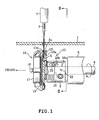
- FIG.1 is a right side view of a full rotary hook unit of the present disclosure;
- FIG. 2 is a rear view of a vertical cross section taken along line II-II of FIG.1 in which the sewing needle is slightly elevated from the lowermost position;
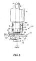
- FIG.3 is a plan view of the full rotary hook unit;
- FIG.4 is a perspective view of the needle guide plate;
- FIG. 5 corresponds to FIG. 2 in which the sewing needle is in the lowermost position; and
- FIG. 6 corresponds to FIG.2 in which the sewing needle is in a position immediately after encountering the beak after starting its elevation.
- Embodiment of the present disclosure will be described with reference to the drawings. A vertical full rotary hook unit of the present embodiment is provided with a vertical full
rotary hook 10, alower shaft 4, and acoupling element 5 connecting thelower shaft 4 and the vertical fullrotary hook 10. The vertical fullrotary hook 10 is provided below aneedle plate 1 of a pattern sewing machine (not shown). - Referring to FIGS.1 to 3, the vertical full
rotary hook 10 is provided with anouter hook 11 rotated by thelower shaft 4, amiddle hook 12 rotatably supported by theouter hook 11, and aloop presser plate 13 provided integrally with the rear side of the.outer hook 11. - The
outer hook 11 is provided with anouter hook body 14 and ahook shaft 15 connecting to theouter hook body 14. Rotational force of thelower shaft 4 rotating in synchronization with a main shaft (not shown) is transmitted to thehook shaft 15 via thecoupling element 5. Thus, theouter hook 11 and thecoupling element 5 are rotated integrally. Transmission of rotational force to thehook shaft 15 causes theouter hook 11 to be rotated clockwise in front view (assuming that the left side of FIG.1 and the lower side of FIG.3 indicate the front direction respectively) about thehook shaft 15 in synchronization with the vertical movement of thesewing needle 3. Theouter hook body 14 has abeak 11a formed thereto which is directed toward the clockwise rotational direction. - The
middle hook 12 is provided with amiddle hook body 17 and ashaft 18, and is fitted co-axially with theouter hook body 14. Themiddle hook 12 and theouter hook 14 support each other rotatably. Theshaft 18 is provided so as to project from the bottom of themiddle hook body 17 to the opened end side of themiddle hook body 17 and supports a bobbin case (not shown) that contains a bobbin (not shown) in a rotatable manner. Thelower shaft 4 is supported rotatably to the bed frame (not shown) by abearing 6. - When rotational force is transmitted to the vertical full
rotary hook 10 by the rotation of thelower shaft 4, theouter hook 11 is rotated clockwise in front view in synchronization with the vertical movement of thesewing needle 3, with themiddle hook 12 and the bobbin case in unrotatable state. The rotation of theouter hook 11 causes a needle thread (not shown) extending from aneye 3a of thesewing needle 3 penetrating the workpiece cloth to be seized by thebeak 11a and carried around themiddle hook 12. Then, the needle thread extending from theeye 3a of thesewing needle 3 is intertwined with the bobbin thread (not shown) extending from the bobbin. Thereafter, the needle thread loop is tightened by a thread take-up (not shown) to form a stitch. - Referring to FIG.2, the
loop presser plate 13 is composed of a plate element taking a substantially semicircular form that surrounds thelower shaft 4 and is secured to the rear side of theouter hook 11 by afastening screw 19 from thecoupling element 5 side (rear side). Referring to FIG. 1, a needle passage S allowing passage of thesewing needle 3 is defined between the rear surface of theouter hook 11 and theloop presser plate 13. As illustrated in FIG.2, theloop presser plate 13 has anotch 13a in predetermined width defined thereto. Thenotch 13a confronts the distal end of thesewing needle 3 during the time period in which theouter hook 11 rotates from a position immediately before the lowermost rotational position (rotational position of theouter hook 11 in which thesewing needle 3 is in a position immediately before the lowermost position) to a post-encounter rotational position (rotational position immediately after thebeak 11a encounters the sewing needle 3). - A description will be given on a
needle guide plate 20 provided inouter hook 11 as the needle guide element hereinafter. - Referring to FIG.4, the
needle guide plate 20 takes a stepped form in side view .(assuming that the left side in FIG.4 indicates the front side) made of plate material, and a securingportion 20a oriented in the longitudinal direction is formed integrally with the right end of thethread guide plate 20. Aneedle guide portion 20c is formed in the upper front end portion of theneedle guide plate 20. The lateral width of thethread guide portion 20c is configured slightly narrower than thenotch 13a of theloop presser plate 13. The securingportion 20a has a longitudinallylong hole 20b defined thereto. - Referring to FIGS.2 and 4, the height of the
needle guide portion 20c is formed in a substantially curved profile such that distal end relative to thebeak 11a is lower than the proximal end relative to thebeak 11a. Theneedle guide plate 20 guides the distal end (lower end) of thesewing needle 3 during a predetermined time period (at least the sum of the predetermined time period immediately before thebeak 11a encounters thesewing needle 3 and the predetermined time period immediately after thesewing needle 3 encounters thebeak 11a) in which thesewing needle 3 in the lowermost position (refer to FIG. 5) is elevated (refer to FIG.2) to the position immediately after encountering thebeak 11a (refer to FIG.6) . In the state illustrated in FIG. 5 (when thesewing needle 3 is in the lowermost position), the rotational angle taken by theouter hook 11 until thebeak 11a encounters thesewing needle 3 is approximately 50 degrees. - The
needle guide plate 20 is formed so as to be sloped relative to the plane perpendicular to the axial direction of thelower shaft 4. As illustrated in FIGS.3 and 4, the distal end relative to thebeak 11a of theneedle guide portion 20c is positioned in themiddle hook 12 side (front side) relative to thebeak 11a in the axial direction of thelower shaft 4. The proximal end relative to thebeak 11a of theneedle guide portion 20c is positioned in substantially the same position as thebeak 11a in the axial direction of thelower shaft 4. As illustrated in FIGS. 1 and 2, theneedle guide portion 20c is positioned in the needle passage S by passing through thenotch 13a of theloop presser plate 13 from the rear side. The proximal end relative to thebeak 11a of theneedle guide portion 20c being positioned in substantially the same position as thebeak 11a denotes that the proximal end relative to thebeak 11a may be positioned slightly in themiddle hook 12 side (front side) relative to thebeak 11a and that the proximal end relative to thebeak 11a may be positioned slightly in thelower shaft 4 side (rear side) relative to thebeak 11a. - Next, a description will be given on a
position adjustment mechanism 22. Theposition adjustment mechanism 22 is mounted on thecoupling element 5 so that its positioning is adjustable in the longitudinal direction (axial direction of the lower shaft 4) within the needle passage S. - Referring to FIG.2, an
orthogonal cut 5a is defined along the shaft direction (longitudinal direction) of thelower shaft 4 in a portion slightly in the right side of the upper end of thecoupling element 5. The securingportion 20a of theneedle guide plate 20 assumes a vertical disposition and is arranged in the longitudinal direction along the vertical wall of thecut 5a. Theneedle guide plate 20 is mounted on thecoupling element 5 so as to allow adjustment in its longitudinal positioning relative to thecoupling element 5 by screwing thefastening screw 23 inserted in thelong hole 20b into the vertical wall of thecut 5a. The securingportion 20a, thelong hole 20b, thefastening screw 23, and thescrew hole 25 of thecoupling element 5 constitute the connection mechanism allowing connection and disconnection of the securingportion 20a formed in theneedle guide plate 20 and thecoupling element 5. The angle in which thecut 5a is cut off is not limited to 90 degrees. - The operation of the above configured vertical full
rotary hook 10 will be described hereinafter. - Before starting a sewing operation, the user is to attach a
sewing needle 3 which is suitable for the thickness and the type of workpeice cloth to be sewn on theneedle bar 2. Then, a hand pulley (not shown) of the pattern sewing machine is manually operated to lower thesewing needle 3 to a state immediately after encountering thebeak 11a (refer to FIG.6). Under such state, thefastening screw 23 is loosened with a tool and positioning of theneedle guide plate 20 is adjusted so as to provide a predetermined clearance between thesewing needle 3 and thebeak 11a (so that the distal end side relative to thebeak 11a of theneedle guide portion 20c rearwardly guides the distal end of the sewing needle 3). Thefastening screw 23 is tightened after adjusting the positioning of theneedle guide plate 20. - After adjustment of the positioning of the
needle guide plate 20, the distal end of theneedle guide portion 20c is positioned in themiddle hook 12 side (front side) relative to thebeak 11a in the longitudinal direction (axial direction of the lower shaft 4). The proximal end relative to thebeak 11a of theneedle guide portion 20c is situated in substantially the same position as thebeak 11a in the longitudinal direction (axial direction of the lower shaft 4). - After adjustment of longitudinal positioning of the
needle guide plate 20, sewing operation is started after the user places the workpiece cloth on aneedle plate 1. When sewing operation is started, theneedle guide portion 20c of theneedle guide plate 20 rearwardly guides the distal end of thesewing needle 3 for a predetermined time period (time period in which thesewing needle 3 in the lowermost position (refer to FIG.5) is elevated to the position immediately after encountering thebeak 11a (refer to FIG.6)) in each sewing cycle. Thus, thesewing needle 3 is able to avoid colliding with thebeak 11a. - As described above, according to the present embodiment, when changing the
sewing needle 3 to a sewing needle of different thickness, the user is allowed to adjust the positioning of theneedle guide plate 20 in the axial direction of thelower shaft 4 via theposition adjustment mechanism 22. The clearance between thesewing needle 3 and thebeak 11a can be readily adjusted by providing theneedle guide plate 20 that rearwardly guides thesewing needle 3 at least for a predetermined time period immediately before thebeak 11a encounters thesewing needle 3. - The securing
portion 20a for mounting theneedle guide plate 20 has been formed integrally with theneedle guide plate 20 and thelong hole 20b elongated in the axial direction of thelower shaft 4 has been defined in the securingportion 20a. - The
position adjustment mechanism 22 secures theneedle guide plate 20 to thecoupling element 5 connecting thelower shaft 4 and theouter hook 11 by thefastening screw 23 inserted in the securingportion 20a and thelong hole 20b so that the positioning of theneedle guide plate 20 is adjustable relative to thecoupling element 5. Thus, the configuration of theposition adjustment mechanism 22 can be simplified. - When using
sewing needles 3 of different thickness, the user is allowed to readily adjust the positioning of theneedle guide plate 20 in the axial direction of thelower shaft 4, which is the direction in which thelong hole 20b is oriented, by merely loosening thefastening screw 23. Thefastening screw 23 can be tightened and loosened with improved workability since thefastening screw 23 is screw fastened to thecoupling element 5. - The heights at both ends of the
needle guide portion 20c are configured to define a substantially curved profile, in which the distal end relative to thebeak 11a is lower than the proximal end relative to thebeak 11a, and theneedle guide portion 20c is arranged to guide the distal end of thesewing needle 3. Theneedle guide portion 20c guides the distal end of the elevatingsewing needle 3 for at least a predetermined time period immediately before thebeak 11a encounters thesewing needle 3. Thus, thebeak 11a is allowed reliably seize the needle thread extending from theeye 3a of thesewing needle 3 with no interference of theneedle guide portion 20c, thereby forming neat continuous stitches without skipped stitches. - An
orthogonal cut 5a has been defined in thecoupling element 5 along the axial direction of thelower shaft 4. Theposition adjustment mechanism 22 is secured to thecut 5a of theneedle guide 20 so as to allow the adjustment of the positioning of theneedle guide plate 20. Thus, thefastening screw 23 can be readily tightened and loosened from the lateral direction of thecoupling element 5. - A
loop presser plate 13 having anotch 13a is provided integrally with the rear side of theouter hook 11 and theneedle guide portion 20c of theneedle guide plate 20 is passed through thenotch 13a from the rear side, thereby, allowing compact configuration of theneedle guide plate 20. - The present disclosure is not limited to the above described embodiment, but may be modified as follows.
- The time period in which the
needle guide portion 20c of theneedle guide plate 20 guides thesewing needle 3 may be arranged at a predetermined time period immediately before thebeak 11a encounters the sewing needle 3 (the time period in which theouter hook 11 has traveled the rotational angle of approximately 10 degrees until thebeak 11a encounters the sewing needle 3) and a predetermined time period immediately after thebeak 11a has encountered the sewing needle 3 (the time period in which theouter hook 11 has traveled the rotational angle of approximately 10 degrees after thebeak 11a has encountered the sewing needle 3). - The present embodiment defines the starting point of the predetermined time period at the lowermost position of the
sewing needle 3, however the starting point may be defined at a position immediately before the lowermost position of thesewing needle 3 or the position immediately after the lowermost position of thesewing needle 3. - A scale may be marked on either one of the securing
portion 20a of theneedle guide plate 20 or thecoupling element 5 on which theneedle guide plate 20 is mounted and a baseline may be marked on the other of the securingportion 20a or thecoupling element 5. Such configuration provides better clarity in the dimension of clearance between thesewing needle 3 and thebeak 11a, and thus, the baseline may be aligned with the optimal scale for the thickness of thesewing needle 3 to be used among plurality types of sewing needles 3. - The securing
portion 20a of theneedle guide plate 20 may be attached on theouter hook 11. - The
needle guide plate 20 may be formed in a curved form in plan view so as to curve along the periphery of theloop presser plate 13 so as to be positioned in the needle passage S by making a U-turn around the outer side of theloop pressing plate 13 from the securingportion 20a. - The connection mechanism of the present embodiment is constituted by the securing
portion 20a, thelong hole 20b, thefastening screw 23, and thescrew hole 25 of thecoupling element 5; however, any configuration may be employed if the securingportion 20a and thecoupling element 5 can be connected or disconnected. - For example, a male-threaded screw may be formed in the
coupling element 5, which male-threaded screw is passed through thelong hole 20b of the securingportion 20a, and a female-threaded nut may be tightened over the securingportion 20a. - Further, the securing
portion 20a may be secured on thecoupling element 5 by a magnet placed over the securingportion 20a. - Further, the securing
portion 20a may be formed in a notched annular shape (C-shape) and fitted with thecoupling element 5 by coupling the notched ends by screws. - The foregoing description and drawings are merely illustrative of the principles of the present disclosure and are not to be construed in a limited sense. Various changes and modifications will become apparent to those of ordinary skill in the art. All such changes and modifications are seen to fall within the scope of the disclosure as defined by the appended claims.
Claims (9)
- A full rotary hook unit provided below a needle plate of a sewing machine and including an outer hook having a beak rotating integrally with a lower shaft in synchronization with
a vertical movement of a sewing needle, and a middle hook rotatably supported by the outer hook, the full rotary hook unit characterized by:a needle guide element that is formed independent of the outer hook and the middle hook, and that guides the sewing needle at least for a predetermined time period immediately before the beak encounters the sewing needle to adjust clearance between the sewing needle and the beak; anda position adjustment mechanism that mounts the needle guide element on the outer hook or an element rotating integrally with the outer hook so as to allow adjustment of the needle guide element in a axial direction of the lower shaft. - The unit of claim 1, characterized in that the element rotating integrally with the outer hook is a coupling element that connects the lower shaft and the outer hook.
- The unit of claim 1 or 2, characterized in that the needle guide element includes a needle guide portion in plate form that confronts the sewing needle, and heights at both ends of the needle guide portion is arranged so that a proximal end relative to the beak is higher than a distal end relative to the beak.
- The unit of claim 3, characterized in that the proximal end relative to the beak of the needle guide portion is in substantially same position as the beak in the axial direction of the lower shaft and the distal end relative to the beak of the needle guide portion is positioned in a middle hook side relative to the beak in the axial direction of the lower shaft.
- The unit of claims 3 or 4, further characterized by a presser plate that is provided integrally with a rear side of the outer hook and that has a notch defined thereto through which the needle guide portion is passed from a rear side.
- The unit of any of claims 2 to 5, characterized in that the position adjustment mechanism includes a connection mechanism capable of connecting and disconnecting a securing portion formed on the needle guide element and the coupling element.
- The unit of claim 6, characterized in that the connection mechanism includes a long hole defined in the securing portion and elongated in the axial direction of the lower shaft, a screw passed through the long hole, and a screw hole defined in the coupling element.
- The unit of claim 6 or 7, characterized in that the coupling element has a cut that is defined by cutting along the axial direction of the lower shaft, and the connection mechanism secures the securing portion to the cut by screw so that the securing portion is adjustable in the axial direction of the lower shaft.
- The unit of any of claims 1 to 8, characterized in that the needle guide element guides the sewing needle for a predetermined time period immediately after the beak has encountered the sewing needle in addition to the predetermined time period immediately before the beak encounters the sewing needle.
Applications Claiming Priority (1)
| Application Number | Priority Date | Filing Date | Title |
|---|---|---|---|
| JP2006222430A JP5048287B2 (en) | 2006-08-17 | 2006-08-17 | Full rotation pot |
Publications (2)
| Publication Number | Publication Date |
|---|---|
| EP1889957A1 true EP1889957A1 (en) | 2008-02-20 |
| EP1889957B1 EP1889957B1 (en) | 2017-10-11 |
Family
ID=38596000
Family Applications (1)
| Application Number | Title | Priority Date | Filing Date |
|---|---|---|---|
| EP07015968.6A Ceased EP1889957B1 (en) | 2006-08-17 | 2007-08-14 | Full rotary hook |
Country Status (4)
| Country | Link |
|---|---|
| EP (1) | EP1889957B1 (en) |
| JP (1) | JP5048287B2 (en) |
| KR (1) | KR100937055B1 (en) |
| CN (1) | CN101130920B (en) |
Cited By (2)
| Publication number | Priority date | Publication date | Assignee | Title |
|---|---|---|---|---|
| KR100937055B1 (en) | 2006-08-17 | 2010-01-15 | 브라더 고오교오 가부시키가이샤 | Fully rotary drum |
| CN102277697A (en) * | 2011-08-05 | 2011-12-14 | 中屹机械工业有限公司 | Unlimited thread feed rotary hook |
Families Citing this family (4)
| Publication number | Priority date | Publication date | Assignee | Title |
|---|---|---|---|---|
| WO2014192108A1 (en) * | 2013-05-29 | 2014-12-04 | 株式会社広瀬製作所 | Needle-handler position adjusting device |
| CN103966783B (en) * | 2014-05-13 | 2015-08-26 | 诸暨市新信机电科技有限公司 | Embroidery machine rotary hook inner shuttle opening device |
| CN110725078A (en) * | 2019-11-29 | 2020-01-24 | 朱健 | Hook device for sewing machine |
| KR102543239B1 (en) * | 2022-10-21 | 2023-06-14 | 고광옥 | Rotary shuttle device for high-speed sewing machine that forms perfect stitch seams |
Citations (2)
| Publication number | Priority date | Publication date | Assignee | Title |
|---|---|---|---|---|
| US3215105A (en) * | 1963-09-09 | 1965-11-02 | Singer Co | Rotary hook for sewing machines |
| US4660485A (en) * | 1980-11-06 | 1987-04-28 | Ssmc Inc. | Rotating needle guard |
Family Cites Families (5)
| Publication number | Priority date | Publication date | Assignee | Title |
|---|---|---|---|---|
| JPH0630709B2 (en) * | 1989-02-27 | 1994-04-27 | 株式会社廣瀬製作所 | Half turn bite |
| JP3010121B2 (en) * | 1994-06-29 | 2000-02-14 | ジューキ株式会社 | Sewing machine needle holder |
| JPH10328461A (en) * | 1997-06-02 | 1998-12-15 | Brother Ind Ltd | Half-turn kettle of sewing machine |
| JP2004313593A (en) | 2003-04-18 | 2004-11-11 | Sabun Kogyosho:Kk | Horizontally rotation shuttle of sewing machine |
| JP5048287B2 (en) | 2006-08-17 | 2012-10-17 | 株式会社廣瀬製作所 | Full rotation pot |
-
2006
- 2006-08-17 JP JP2006222430A patent/JP5048287B2/en not_active Expired - Fee Related
-
2007
- 2007-08-10 CN CN2007101419559A patent/CN101130920B/en not_active Expired - Fee Related
- 2007-08-14 EP EP07015968.6A patent/EP1889957B1/en not_active Ceased
- 2007-08-16 KR KR1020070082262A patent/KR100937055B1/en not_active Expired - Fee Related
Patent Citations (2)
| Publication number | Priority date | Publication date | Assignee | Title |
|---|---|---|---|---|
| US3215105A (en) * | 1963-09-09 | 1965-11-02 | Singer Co | Rotary hook for sewing machines |
| US4660485A (en) * | 1980-11-06 | 1987-04-28 | Ssmc Inc. | Rotating needle guard |
Cited By (2)
| Publication number | Priority date | Publication date | Assignee | Title |
|---|---|---|---|---|
| KR100937055B1 (en) | 2006-08-17 | 2010-01-15 | 브라더 고오교오 가부시키가이샤 | Fully rotary drum |
| CN102277697A (en) * | 2011-08-05 | 2011-12-14 | 中屹机械工业有限公司 | Unlimited thread feed rotary hook |
Also Published As
| Publication number | Publication date |
|---|---|
| JP2008043549A (en) | 2008-02-28 |
| JP5048287B2 (en) | 2012-10-17 |
| CN101130920A (en) | 2008-02-27 |
| EP1889957B1 (en) | 2017-10-11 |
| KR20080016480A (en) | 2008-02-21 |
| CN101130920B (en) | 2011-11-16 |
| KR100937055B1 (en) | 2010-01-15 |
Similar Documents
| Publication | Publication Date | Title |
|---|---|---|
| EP1889957B1 (en) | Full rotary hook | |
| JP4036353B2 (en) | Feed dog height adjustment mechanism | |
| AU642051B2 (en) | A presser foot having an adjustable guide for sequins and ribbon | |
| JP3186538U (en) | Threading blade for sewing machine, thread cutting assembly, and sewing machine equipped with this kind of threading blade | |
| KR101565618B1 (en) | Feeder for feeding fabric during the operation of a sewing machine | |
| CN219410149U (en) | A rotary hook frame, a rotary hook structure and a sewing machine thereof | |
| JP2009055966A (en) | sewing machine | |
| KR20230144465A (en) | Sewing machine | |
| JP2013202145A (en) | sewing machine | |
| CN111691081A (en) | Bottom thread supply device of sewing machine | |
| JP2024004096A (en) | Presser foot device and sewing machine | |
| US20130255555A1 (en) | Sewing machine | |
| JP2002035457A (en) | Vertical hook of sewing machine | |
| CN222557220U (en) | Needle protection transmission mechanism and seam splicing machine | |
| US5881659A (en) | Bobbin thread cutting device of a sewing machine | |
| CN219527009U (en) | Rotating shuttle positioning device, machine head and embroidery machine | |
| JP5021245B2 (en) | Bobbin case | |
| JP2002306879A (en) | Double lock stitch sewing machine with rotating safety structure for bobbin case | |
| CN102691177B (en) | Button hole sewing machine and the method for making the buttonhole linear slit with lacing thread | |
| JP3391684B2 (en) | Sewing presser | |
| US2921545A (en) | Sewing machine presser bar mechanisms | |
| US4398482A (en) | Stitch length stops for industrial sewing machine | |
| JPS645594Y2 (en) | ||
| JPH0810478A (en) | Sewing machine needle receiving device | |
| JP2009261949A (en) | Bobbin housing, hook with such bobbin housing, and sewing machine with such hook |
Legal Events
| Date | Code | Title | Description |
|---|---|---|---|
| PUAI | Public reference made under article 153(3) epc to a published international application that has entered the european phase |
Free format text: ORIGINAL CODE: 0009012 |
|
| AK | Designated contracting states |
Kind code of ref document: A1 Designated state(s): AT BE BG CH CY CZ DE DK EE ES FI FR GB GR HU IE IS IT LI LT LU LV MC MT NL PL PT RO SE SI SK TR |
|
| AX | Request for extension of the european patent |
Extension state: AL BA HR MK YU |
|
| 17P | Request for examination filed |
Effective date: 20080620 |
|
| AKX | Designation fees paid |
Designated state(s): DE IT |
|
| 17Q | First examination report despatched |
Effective date: 20160824 |
|
| GRAP | Despatch of communication of intention to grant a patent |
Free format text: ORIGINAL CODE: EPIDOSNIGR1 |
|
| INTG | Intention to grant announced |
Effective date: 20170410 |
|
| GRAS | Grant fee paid |
Free format text: ORIGINAL CODE: EPIDOSNIGR3 |
|
| GRAA | (expected) grant |
Free format text: ORIGINAL CODE: 0009210 |
|
| AK | Designated contracting states |
Kind code of ref document: B1 Designated state(s): DE IT |
|
| REG | Reference to a national code |
Ref country code: DE Ref legal event code: R096 Ref document number: 602007052630 Country of ref document: DE |
|
| REG | Reference to a national code |
Ref country code: DE Ref legal event code: R097 Ref document number: 602007052630 Country of ref document: DE |
|
| PLBE | No opposition filed within time limit |
Free format text: ORIGINAL CODE: 0009261 |
|
| STAA | Information on the status of an ep patent application or granted ep patent |
Free format text: STATUS: NO OPPOSITION FILED WITHIN TIME LIMIT |
|
| 26N | No opposition filed |
Effective date: 20180712 |
|
| PGFP | Annual fee paid to national office [announced via postgrant information from national office to epo] |
Ref country code: DE Payment date: 20180731 Year of fee payment: 12 Ref country code: IT Payment date: 20180823 Year of fee payment: 12 |
|
| REG | Reference to a national code |
Ref country code: DE Ref legal event code: R119 Ref document number: 602007052630 Country of ref document: DE |
|
| PG25 | Lapsed in a contracting state [announced via postgrant information from national office to epo] |
Ref country code: DE Free format text: LAPSE BECAUSE OF NON-PAYMENT OF DUE FEES Effective date: 20200303 |
|
| PG25 | Lapsed in a contracting state [announced via postgrant information from national office to epo] |
Ref country code: IT Free format text: LAPSE BECAUSE OF NON-PAYMENT OF DUE FEES Effective date: 20190814 |