EP1887892B1 - Systeme und verfahren zur verringerung des drucks in einer druckkammer - Google Patents
Systeme und verfahren zur verringerung des drucks in einer druckkammer Download PDFInfo
- Publication number
- EP1887892B1 EP1887892B1 EP06765441A EP06765441A EP1887892B1 EP 1887892 B1 EP1887892 B1 EP 1887892B1 EP 06765441 A EP06765441 A EP 06765441A EP 06765441 A EP06765441 A EP 06765441A EP 1887892 B1 EP1887892 B1 EP 1887892B1
- Authority
- EP
- European Patent Office
- Prior art keywords
- pressure
- pressure chamber
- valve
- main
- chamber
- Prior art date
- Legal status (The legal status is an assumption and is not a legal conclusion. Google has not performed a legal analysis and makes no representation as to the accuracy of the status listed.)
- Active
Links
Images
Classifications
-
- A—HUMAN NECESSITIES
- A23—FOODS OR FOODSTUFFS; TREATMENT THEREOF, NOT COVERED BY OTHER CLASSES
- A23B—PRESERVATION OF FOODS, FOODSTUFFS OR NON-ALCOHOLIC BEVERAGES; CHEMICAL RIPENING OF FRUIT OR VEGETABLES
- A23B2/00—Preservation of foods or foodstuffs, in general
- A23B2/10—Preservation of foods or foodstuffs, in general by treatment with pressure variation, shock, acceleration or shear stress
- A23B2/103—Preservation of foods or foodstuffs, in general by treatment with pressure variation, shock, acceleration or shear stress using sub- or super-atmospheric pressures, or pressure variations transmitted by a liquid or gas
-
- F—MECHANICAL ENGINEERING; LIGHTING; HEATING; WEAPONS; BLASTING
- F17—STORING OR DISTRIBUTING GASES OR LIQUIDS
- F17C—VESSELS FOR CONTAINING OR STORING COMPRESSED, LIQUEFIED OR SOLIDIFIED GASES; FIXED-CAPACITY GAS-HOLDERS; FILLING VESSELS WITH, OR DISCHARGING FROM VESSELS, COMPRESSED, LIQUEFIED, OR SOLIDIFIED GASES
- F17C7/00—Methods or apparatus for discharging liquefied, solidified, or compressed gases from pressure vessels, not covered by another subclass
-
- F—MECHANICAL ENGINEERING; LIGHTING; HEATING; WEAPONS; BLASTING
- F17—STORING OR DISTRIBUTING GASES OR LIQUIDS
- F17C—VESSELS FOR CONTAINING OR STORING COMPRESSED, LIQUEFIED OR SOLIDIFIED GASES; FIXED-CAPACITY GAS-HOLDERS; FILLING VESSELS WITH, OR DISCHARGING FROM VESSELS, COMPRESSED, LIQUEFIED, OR SOLIDIFIED GASES
- F17C2201/00—Vessel construction, in particular geometry, arrangement or size
- F17C2201/01—Shape
- F17C2201/0104—Shape cylindrical
-
- F—MECHANICAL ENGINEERING; LIGHTING; HEATING; WEAPONS; BLASTING
- F17—STORING OR DISTRIBUTING GASES OR LIQUIDS
- F17C—VESSELS FOR CONTAINING OR STORING COMPRESSED, LIQUEFIED OR SOLIDIFIED GASES; FIXED-CAPACITY GAS-HOLDERS; FILLING VESSELS WITH, OR DISCHARGING FROM VESSELS, COMPRESSED, LIQUEFIED, OR SOLIDIFIED GASES
- F17C2205/00—Vessel construction, in particular mounting arrangements, attachments or identifications means
- F17C2205/03—Fluid connections, filters, valves, closure means or other attachments
- F17C2205/0302—Fittings, valves, filters, or components in connection with the gas storage device
- F17C2205/0323—Valves
- F17C2205/0326—Valves electrically actuated
-
- F—MECHANICAL ENGINEERING; LIGHTING; HEATING; WEAPONS; BLASTING
- F17—STORING OR DISTRIBUTING GASES OR LIQUIDS
- F17C—VESSELS FOR CONTAINING OR STORING COMPRESSED, LIQUEFIED OR SOLIDIFIED GASES; FIXED-CAPACITY GAS-HOLDERS; FILLING VESSELS WITH, OR DISCHARGING FROM VESSELS, COMPRESSED, LIQUEFIED, OR SOLIDIFIED GASES
- F17C2205/00—Vessel construction, in particular mounting arrangements, attachments or identifications means
- F17C2205/03—Fluid connections, filters, valves, closure means or other attachments
- F17C2205/0302—Fittings, valves, filters, or components in connection with the gas storage device
- F17C2205/035—Flow reducers
-
- F—MECHANICAL ENGINEERING; LIGHTING; HEATING; WEAPONS; BLASTING
- F17—STORING OR DISTRIBUTING GASES OR LIQUIDS
- F17C—VESSELS FOR CONTAINING OR STORING COMPRESSED, LIQUEFIED OR SOLIDIFIED GASES; FIXED-CAPACITY GAS-HOLDERS; FILLING VESSELS WITH, OR DISCHARGING FROM VESSELS, COMPRESSED, LIQUEFIED, OR SOLIDIFIED GASES
- F17C2223/00—Handled fluid before transfer, i.e. state of fluid when stored in the vessel or before transfer from the vessel
- F17C2223/01—Handled fluid before transfer, i.e. state of fluid when stored in the vessel or before transfer from the vessel characterised by the phase
- F17C2223/0146—Two-phase
- F17C2223/0153—Liquefied gas, e.g. LPG, GPL
-
- F—MECHANICAL ENGINEERING; LIGHTING; HEATING; WEAPONS; BLASTING
- F17—STORING OR DISTRIBUTING GASES OR LIQUIDS
- F17C—VESSELS FOR CONTAINING OR STORING COMPRESSED, LIQUEFIED OR SOLIDIFIED GASES; FIXED-CAPACITY GAS-HOLDERS; FILLING VESSELS WITH, OR DISCHARGING FROM VESSELS, COMPRESSED, LIQUEFIED, OR SOLIDIFIED GASES
- F17C2223/00—Handled fluid before transfer, i.e. state of fluid when stored in the vessel or before transfer from the vessel
- F17C2223/03—Handled fluid before transfer, i.e. state of fluid when stored in the vessel or before transfer from the vessel characterised by the pressure level
- F17C2223/036—Very high pressure (>80 bar)
-
- F—MECHANICAL ENGINEERING; LIGHTING; HEATING; WEAPONS; BLASTING
- F17—STORING OR DISTRIBUTING GASES OR LIQUIDS
- F17C—VESSELS FOR CONTAINING OR STORING COMPRESSED, LIQUEFIED OR SOLIDIFIED GASES; FIXED-CAPACITY GAS-HOLDERS; FILLING VESSELS WITH, OR DISCHARGING FROM VESSELS, COMPRESSED, LIQUEFIED, OR SOLIDIFIED GASES
- F17C2227/00—Transfer of fluids, i.e. method or means for transferring the fluid; Heat exchange with the fluid
- F17C2227/01—Propulsion of the fluid
- F17C2227/0128—Propulsion of the fluid with pumps or compressors
- F17C2227/0135—Pumps
-
- F—MECHANICAL ENGINEERING; LIGHTING; HEATING; WEAPONS; BLASTING
- F17—STORING OR DISTRIBUTING GASES OR LIQUIDS
- F17C—VESSELS FOR CONTAINING OR STORING COMPRESSED, LIQUEFIED OR SOLIDIFIED GASES; FIXED-CAPACITY GAS-HOLDERS; FILLING VESSELS WITH, OR DISCHARGING FROM VESSELS, COMPRESSED, LIQUEFIED, OR SOLIDIFIED GASES
- F17C2227/00—Transfer of fluids, i.e. method or means for transferring the fluid; Heat exchange with the fluid
- F17C2227/04—Methods for emptying or filling
- F17C2227/047—Methods for emptying or filling by repeating a process cycle
-
- F—MECHANICAL ENGINEERING; LIGHTING; HEATING; WEAPONS; BLASTING
- F17—STORING OR DISTRIBUTING GASES OR LIQUIDS
- F17C—VESSELS FOR CONTAINING OR STORING COMPRESSED, LIQUEFIED OR SOLIDIFIED GASES; FIXED-CAPACITY GAS-HOLDERS; FILLING VESSELS WITH, OR DISCHARGING FROM VESSELS, COMPRESSED, LIQUEFIED, OR SOLIDIFIED GASES
- F17C2250/00—Accessories; Control means; Indicating, measuring or monitoring of parameters
- F17C2250/03—Control means
- F17C2250/032—Control means using computers
-
- F—MECHANICAL ENGINEERING; LIGHTING; HEATING; WEAPONS; BLASTING
- F17—STORING OR DISTRIBUTING GASES OR LIQUIDS
- F17C—VESSELS FOR CONTAINING OR STORING COMPRESSED, LIQUEFIED OR SOLIDIFIED GASES; FIXED-CAPACITY GAS-HOLDERS; FILLING VESSELS WITH, OR DISCHARGING FROM VESSELS, COMPRESSED, LIQUEFIED, OR SOLIDIFIED GASES
- F17C2250/00—Accessories; Control means; Indicating, measuring or monitoring of parameters
- F17C2250/04—Indicating or measuring of parameters as input values
- F17C2250/0404—Parameters indicated or measured
- F17C2250/0408—Level of content in the vessel
-
- F—MECHANICAL ENGINEERING; LIGHTING; HEATING; WEAPONS; BLASTING
- F17—STORING OR DISTRIBUTING GASES OR LIQUIDS
- F17C—VESSELS FOR CONTAINING OR STORING COMPRESSED, LIQUEFIED OR SOLIDIFIED GASES; FIXED-CAPACITY GAS-HOLDERS; FILLING VESSELS WITH, OR DISCHARGING FROM VESSELS, COMPRESSED, LIQUEFIED, OR SOLIDIFIED GASES
- F17C2250/00—Accessories; Control means; Indicating, measuring or monitoring of parameters
- F17C2250/04—Indicating or measuring of parameters as input values
- F17C2250/0404—Parameters indicated or measured
- F17C2250/043—Pressure
-
- F—MECHANICAL ENGINEERING; LIGHTING; HEATING; WEAPONS; BLASTING
- F17—STORING OR DISTRIBUTING GASES OR LIQUIDS
- F17C—VESSELS FOR CONTAINING OR STORING COMPRESSED, LIQUEFIED OR SOLIDIFIED GASES; FIXED-CAPACITY GAS-HOLDERS; FILLING VESSELS WITH, OR DISCHARGING FROM VESSELS, COMPRESSED, LIQUEFIED, OR SOLIDIFIED GASES
- F17C2250/00—Accessories; Control means; Indicating, measuring or monitoring of parameters
- F17C2250/04—Indicating or measuring of parameters as input values
- F17C2250/0404—Parameters indicated or measured
- F17C2250/0443—Flow or movement of content
-
- F—MECHANICAL ENGINEERING; LIGHTING; HEATING; WEAPONS; BLASTING
- F17—STORING OR DISTRIBUTING GASES OR LIQUIDS
- F17C—VESSELS FOR CONTAINING OR STORING COMPRESSED, LIQUEFIED OR SOLIDIFIED GASES; FIXED-CAPACITY GAS-HOLDERS; FILLING VESSELS WITH, OR DISCHARGING FROM VESSELS, COMPRESSED, LIQUEFIED, OR SOLIDIFIED GASES
- F17C2250/00—Accessories; Control means; Indicating, measuring or monitoring of parameters
- F17C2250/04—Indicating or measuring of parameters as input values
- F17C2250/0404—Parameters indicated or measured
- F17C2250/0447—Composition; Humidity
- F17C2250/0452—Concentration of a product
-
- F—MECHANICAL ENGINEERING; LIGHTING; HEATING; WEAPONS; BLASTING
- F17—STORING OR DISTRIBUTING GASES OR LIQUIDS
- F17C—VESSELS FOR CONTAINING OR STORING COMPRESSED, LIQUEFIED OR SOLIDIFIED GASES; FIXED-CAPACITY GAS-HOLDERS; FILLING VESSELS WITH, OR DISCHARGING FROM VESSELS, COMPRESSED, LIQUEFIED, OR SOLIDIFIED GASES
- F17C2250/00—Accessories; Control means; Indicating, measuring or monitoring of parameters
- F17C2250/06—Controlling or regulating of parameters as output values
- F17C2250/0605—Parameters
- F17C2250/0626—Pressure
-
- F—MECHANICAL ENGINEERING; LIGHTING; HEATING; WEAPONS; BLASTING
- F17—STORING OR DISTRIBUTING GASES OR LIQUIDS
- F17C—VESSELS FOR CONTAINING OR STORING COMPRESSED, LIQUEFIED OR SOLIDIFIED GASES; FIXED-CAPACITY GAS-HOLDERS; FILLING VESSELS WITH, OR DISCHARGING FROM VESSELS, COMPRESSED, LIQUEFIED, OR SOLIDIFIED GASES
- F17C2250/00—Accessories; Control means; Indicating, measuring or monitoring of parameters
- F17C2250/06—Controlling or regulating of parameters as output values
- F17C2250/0605—Parameters
- F17C2250/0636—Flow or movement of content
-
- F—MECHANICAL ENGINEERING; LIGHTING; HEATING; WEAPONS; BLASTING
- F17—STORING OR DISTRIBUTING GASES OR LIQUIDS
- F17C—VESSELS FOR CONTAINING OR STORING COMPRESSED, LIQUEFIED OR SOLIDIFIED GASES; FIXED-CAPACITY GAS-HOLDERS; FILLING VESSELS WITH, OR DISCHARGING FROM VESSELS, COMPRESSED, LIQUEFIED, OR SOLIDIFIED GASES
- F17C2260/00—Purposes of gas storage and gas handling
- F17C2260/03—Dealing with losses
- F17C2260/035—Dealing with losses of fluid
- F17C2260/037—Handling leaked fluid
-
- F—MECHANICAL ENGINEERING; LIGHTING; HEATING; WEAPONS; BLASTING
- F17—STORING OR DISTRIBUTING GASES OR LIQUIDS
- F17C—VESSELS FOR CONTAINING OR STORING COMPRESSED, LIQUEFIED OR SOLIDIFIED GASES; FIXED-CAPACITY GAS-HOLDERS; FILLING VESSELS WITH, OR DISCHARGING FROM VESSELS, COMPRESSED, LIQUEFIED, OR SOLIDIFIED GASES
- F17C2270/00—Applications
- F17C2270/05—Applications for industrial use
-
- Y—GENERAL TAGGING OF NEW TECHNOLOGICAL DEVELOPMENTS; GENERAL TAGGING OF CROSS-SECTIONAL TECHNOLOGIES SPANNING OVER SEVERAL SECTIONS OF THE IPC; TECHNICAL SUBJECTS COVERED BY FORMER USPC CROSS-REFERENCE ART COLLECTIONS [XRACs] AND DIGESTS
- Y10—TECHNICAL SUBJECTS COVERED BY FORMER USPC
- Y10T—TECHNICAL SUBJECTS COVERED BY FORMER US CLASSIFICATION
- Y10T137/00—Fluid handling
- Y10T137/0318—Processes
- Y10T137/0396—Involving pressure control
-
- Y—GENERAL TAGGING OF NEW TECHNOLOGICAL DEVELOPMENTS; GENERAL TAGGING OF CROSS-SECTIONAL TECHNOLOGIES SPANNING OVER SEVERAL SECTIONS OF THE IPC; TECHNICAL SUBJECTS COVERED BY FORMER USPC CROSS-REFERENCE ART COLLECTIONS [XRACs] AND DIGESTS
- Y10—TECHNICAL SUBJECTS COVERED BY FORMER USPC
- Y10T—TECHNICAL SUBJECTS COVERED BY FORMER US CLASSIFICATION
- Y10T137/00—Fluid handling
- Y10T137/7722—Line condition change responsive valves
- Y10T137/7758—Pilot or servo controlled
- Y10T137/7761—Electrically actuated valve
-
- Y—GENERAL TAGGING OF NEW TECHNOLOGICAL DEVELOPMENTS; GENERAL TAGGING OF CROSS-SECTIONAL TECHNOLOGIES SPANNING OVER SEVERAL SECTIONS OF THE IPC; TECHNICAL SUBJECTS COVERED BY FORMER USPC CROSS-REFERENCE ART COLLECTIONS [XRACs] AND DIGESTS
- Y10—TECHNICAL SUBJECTS COVERED BY FORMER USPC
- Y10T—TECHNICAL SUBJECTS COVERED BY FORMER US CLASSIFICATION
- Y10T137/00—Fluid handling
- Y10T137/7722—Line condition change responsive valves
- Y10T137/7758—Pilot or servo controlled
- Y10T137/7762—Fluid pressure type
Definitions
- the invention generally relates to the field of high-pressure chambers for processing organic or inorganic substances.
- the invention relates to systems and methods of reducing the pressure in a highly pressurized chamber in a controlled manner over a selected period of time.
- Highly pressurized chambers are used in a variety of industries in the processing of organic or inorganic substances and can operate at pressures from 2000 to over 7,000 times atmospheric pressure.
- high-pressure processing is used to inactivate, sterilize or modify biological substances, to include a variety of medicines and drugs, for example.
- pressure chambers are used to process food substances to inactivate pathogens and microorganisms in the food.
- Pressure treating food substances does not expose foods to the potentially damaging effects of high temperatures and therefore helps to improve the food's palatability, nutritional quality, texture, color, and can also be used as a means of preservation without adding preservatives.
- High-pressure treatment may take place at initial product temperatures ranging from below room temperature to temperatures. approaching 100C. Pressure treated food substances such as ready-to-eat meats, prepared vegetables, fruit juices, and other products have benefited from high-pressure processing.
- Pressure processing can have significant benefits in terms of changed protein function, enhanced or reduced enzyme action, and cellular membrane destruction. These effects can lead to the inactivation of certain microorganisms. Small macromolecules that are responsible for flavor, color, odor, and nutrition, are typically not changed by pressure.
- High-pressure processing compresses and dissolves gas present in the product, thus rapid depressurization may result in greater cellular damage due to a rapid expansion of the gas. Controlled depressurization can control the texture of the resulting product. Also, since pressure is one of the primary thermodynamic variables controlling complex biomolecular structure, high-pressure can be used to modify biomolecular conformation state. Some biomolecules have high sensitivity to variations in temperature or pressure. Thus, for the use of high-pressure to process these substances, a precise control of processing parameters thoughout the processing cycle is preferred. These parameters include: pressure, temperature, time at pressure, rate of pressurization, and rate of depressurization. The ability to reduce pressure in a controlled manner allows for delicate structures to remain near equilibrium. For example, dissolved gas will be able to diffuse from structures without cellular rupture and meta-stable conformational molecular states may be better retained.
- the current approach used to depressurize a high-pressure chamber is to open a small orifice and allow the pressure to rapidly decrease by venting fluid from the pressure chamber through the small orifice. This approach achieves a depressurization time of merely a few minutes, which is not slow enough to prevent structure disruption.
- the use of direct venting also is more difficult when the processing volume is small. Even a small leak will cause a significant loss of pressure.
- EP 0713654 considered as closest prior art discloses a device and a method for processing high-pressure liquid material.
- the liquid material itself is pressurized and supplied under high pressure into a pressurization chamber, c.f. col. 6,1. 17 - 49. Thereafter, the high-pressure liquid material is supplied to a depressurization device for depressurization thereof.
- WO 2004/000451 discloses a high pressure pressing device and a method, wherein decompression of the pressure vessel after a load has been pressed, is performed by removing used pressure medium in two steps. In a first step, a portion of the pressure medium is removed to cause the pressure in the pressure vessel to drop to an intermediate pressure. In a second step, the rest of the pressure medium is released causing the pressure in the pressure vessel to drop to a low pressure.
- the object of the present invention is to provide an improved system and method for reducing the pressure in a highly pressurized chamber in a controlled manner over a selected period of time.
- a system to reduce the pressure in a main pressure chamber comprising a first valve in fluid communication with the main pressure chamber; an intermediate pressure chamber to at least temporarily receive an amount of pressurized fluid that passes through the first valve from the main pressure chamber; a second valve controllably coupled with the first valve and configured to periodically reduce the pressure in the intermediate pressure chamber; at least one sensor coupled to the main pressure chamber to detect a change in a first parameter associated with the main pressure chamber; and a control system responsive to the at least one sensor to controllably operate the first and second valves such that the pressure in the main pressure chamber is incrementally decreased over a substantial amount of time.
- a method of performing a stepwise depressurization of a main high-pressure chamber over a selected period of time comprises the steps of controllably opening a first valve to allow an amount of fluid from the main high-pressure chamber to pass through the first valve; receiving at least some of the amount of fluid that passed through the first valve into a second pressure chamber; closing the first valve when a desired pressure reduction is achieved in the main high-pressure chamber; and controllably opening a second valve to allow pressurized fluid in the second pressure chamber to pass through the second valve after the first valve is closed.
- a system for performing a stepwise depressurization of a main high-pressure chamber over a selected period of time comprises first valve means for permitting a first amount of pressurized fluid to exit from the main high-pressure chamber when the first valve means is in an open position; receiving means for receiving the first amount of pressurized fluid that passes through the first valve means; second valve means for permitting a second amount of pressurized fluid to exit from the receiving means when the second valve means is in an open position; and control means for sequentially controlling the opening and closing of the first valve means and the second valve means to controllably depressurize the main high-pressure chamber over the selected period of time.
- the present invention relates to systems and methods for performing a stepwise depressurization of a high-pressure chamber over a selected, relatively long period of time.
- At least two valves are controllably opened and closed in a sequence to release a predetermined amount of pressure from a high-pressure chamber.
- At least some of the pressurized fluid released from the high-pressure chamber is stored, at least temporarily, in a second pressure chamber.
- the second pressure chamber is located between the two valves.
- a control system controls the valves in response to a signal from at least one pressure sensor coupled to the high-pressure chamber.
- Additional components can be included in the system such as a pressure intensifier and a high-pressure pump, both coupled to the high-pressure chamber.
- at least one additional pressure sensor can operate with the first pressure sensor to improve the accuracy of the measured pressure in the high-pressure chamber.
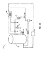
- Figure 1A is a schematic view of a system for depressurizing a main pressure chamber in a controlled manner according to one illustrated embodiment.
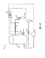
- Figure 1B is a schematic view of a system for depressurizing a main pressure chamber in a controlled manner and temporarily storing a volume of fluid in a second pressure chamber according to another illustrated embodiment.
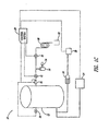
- Figure 1C is a schematic view of a system for depressurizing a main pressure chamber in a controlled manner and detecting a pressure drop in the main pressure chamber with alternate measuring devices according to one illustrated embodiment.
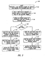
- Figure 2 is a flowchart for a method of depressurizing a main pressure chamber in a controlled manner according to one embodiment.
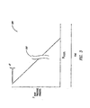
- Figure 3 is a diagram showing a stepwise depressurization of a main pressure chamber according to one embodiment.
- the following description relates generally to systems and methods of depressurizing a highly pressured liquid filled chamber in a controlled manner over a selected, relatively long period of time as compared to conventional systems.
- the systems and methods, as described herein may reduce, minimize or even eliminate undesired effects on the substances being processed when the pressure chamber is depressurized at too fast of a rate.
- the selected pressure will vary depending on the application, pressures in the range of 200-600 MPa or more are often used and thought of when referring to high-pressure processing. It will be understood that other variables in the process are also selected according to the application, as determined by one of ordinary skill in the art. These other variables include such things as the temperature at which the substance is processed and the amount of time the substance is held under pressure, commonly referred to as the dwell time or hold time.
- pressure processing of a substance for example, to destroy microorganisms
- a substance to be pressure treated is placed into a carrier that is in turn placed into a pressure chamber filled with pressure media, for example, water.
- the pressure chamber is closed and pressurized to a selected pressure, which is held for a selected period of time. After the selected period of time, the pressure chamber is rapidly depressurized by venting the pressurized fluid through an orifice, and then the treated product is removed from the pressure vessel.
- FIG 1A shows a system 10 to depressurize a main pressure chamber 12 according to one illustrated and exemplifying embodiment.
- the system 10 includes a second pressure chamber 14, a first valve 16, a second valve 18, a control system 20, and at least one pressure sensor 22, also commonly referred to as a transducer.
- the second pressure chamber 14 is configured with a sufficient volume to at least temporarily receive an amount of pressurized fluid that is permitted to flow through the first valve 16 from the main pressure chamber 12.
- the second pressure chamber 14 is a pressure vessel that is significantly smaller than the main pressure chamber 12.
- the second pressure chamber 14a is a tube located between the first valve 16 and the second valve 18.
- the first valve 16 is located between the main pressure chamber 12 and the second pressure chamber 14 and is configured to allow an amount of pressurized fluid from the main pressure vessel 12 to enter the second pressure chamber 14 when the first valve 16 is open.
- the second valve 18 is located downstream of the second pressure chamber 14.
- the first valve 16 and the second valve 18 are sequentially controlled to establish a stepwise depressurization of the main pressure chamber 12 as described in the operational description below.
- the control system 20 is a programmable logic controller (PLC) according to the illustrated embodiment. However, it is understood and appreciated that other types of microprocessors and systems that are capable of automated timing and pressure monitoring can be used instead of the PLC.
- PLC programmable logic controller
- the control system 20 is coupled to the first valve 16, the second valve 18, and the at least one pressure sensor 22. In one embodiment, the control system 20 is also coupled to a high-pressure pump 24 and a smaller capacity high-pressure backup source 28.
- the control system 20 receives signals from the at least one pressure sensor 22 and uses this information to control the first valve 16, the second valve 18, the high-pressure pump 24, and the high-pressure backup source 28, according to a number of operational parameters programmed into the control system 20.
- the operational parameters and/or recorded operational data can be downloaded from the control system 20 or uploaded to the control system 20 through a serial communications link.
- the control system 20 communicates with the first valve 16, the second valve 18, the high-pressure pump 24, and the high-pressure backup source 28 electrically, electro-optically, and/or electro-magnetically.
- the at least one pressure sensor 22 is coupled to the main pressure chamber 12 to monitor the pressure therein.
- two pressure sensors 22 are actually shown.
- One reason for having two pressure sensors 22 is to improve the resolution of the pressure measurement and to account for any limits on the accuracy of the type of pressure sensor being used. Further, measuring the pressure with multiple pressure sensors 22 can make the system more redundant, for example if one pressure sensor 22 malfunctions or is improperly calibrated for some reason. Multiple pressure sensors 22 can also be used as a diagnostic tool, for example to determine when one of the pressure sensors 22 requires re-calibration.
- each sensor 22 independently measures the pressure in the main pressure chamber 12.
- the control logic in the controller 20 combines the measured pressure values and calculates an average pressure.
- This average pressure can be the pressure measurement that is transferred in the programmable logic to ultimately control at least some of the other components in the system, such as the first valve 16, for example.
- additional pressure sensors 22 i.e., more than two pressure sensors
- the control logic of the controller 20 combines the measured pressure values and calculated pressure changes based on a volume of fluid released per valve operation cycle.
- the high-pressure pump 24 is used to initially pressurize the main pressure chamber 12 before each operational cycle.
- the high-pressure pump 24 can also be utilized to pressurize the high-pressure backup source 28.
- the high-pressure backup source 28, coupled to a programmable high-pressure intensifier/pump 26, can be used to maintain a programmed pressure in the main pressure chamber 12.
- One reason for having the high-pressure backup source 28 coupled to a programmable high-pressure intensifier/pump 26 is to allow the system 10 to adjust for small leakages from the valves or from the seals of the main pressure chamber, which could cause an undesired decrease of the pressure in the main pressure chamber 12.
- the high-pressure backup source 28 is a reservoir, whereas one type of programmable high-pressure intensifier/pump 26 is an air-over-oil intensifier pump to operate an oil-over-water high-pressure intensifier 26, according to one embodiment.
- the system 10 includes a flow restrictor 30, a drain 32, and a pressure sensor 34 coupled to the second pressure chamber 14 according to the illustrated embodiment.
- the flow restrictor 30 may take many forms, in one embodiment the flow restrictor 30 functions as a backpressure device having a loop of small diameter coil tubing that restricts the flow of pressurized fluid coming from the second valve 18.
- the flow restrictor 30 creates a backpressure (i.e., positive pressure) at the second valve 18 to slow the depressurization rate of the second pressure chamber 14 as the second pressure chamber 14 approaches atmospheric pressure.
- the flow restrictor 30 is an optional component that may be used in the high-pressure system described above to maintain a positive pressure in the second pressure chamber 14. Maintaining the positive pressure in the second pressure chamber 14 helps to reduce cavitation within the second valve 18 and thus reduce or minimize cavitation damage to the valve components. In low-pressure systems (i.e., ⁇ 200 MPa), however, cavitation is not a severe problem. Accordingly, it is understood that the flow restrictor 30 is not needed for low-pressure systems.
- the drain 32 receives the depressurized fluid and either discharges the fluid or routes the fluid to a re-circulation unit (not shown).
- a sensor 34 such as a fluid level sensor and/or pressure sensor, is coupled to the second pressure chamber 14 to monitor the fluid level and/or pressure of the second pressure chamber 14.
- a sensor 34 such as a fluid level sensor and/or pressure sensor, is coupled to the second pressure chamber 14 to monitor the fluid level and/or pressure of the second pressure chamber 14.
- Figure 1C shows yet another embodiment of the system 10 that utilizes a measurement device coupled to the main pressure chamber 12 to detect a change in a first parameter associated with the main pressure chamber 12.
- the measurement device could be a volumetric flow rate monitor 36 and/or a fluid density meter 38.
- FIG. 2 shows a flowchart describing an operational method 100 for slowly depressurizing a pressure chamber 12 according to one embodiment.
- the main pressure chamber 12 is initially pressurized at step 102.
- the initial pressurization of the main pressure chamber 12 is accomplished using a high-pressure pump 24 coupled to the main pressure chamber 12.
- the programmable high-pressure intensifier/pump 26 coupled to the high-pressure backup source 28 is used to maintain the pressure in the main pressure chamber 12.
- the programmable high-pressure intensifier/pump 26, coupled to the control system 20 is controllably operated to maintain the pressure in the main pressure chamber 12, not only during the hold time, but also at any time during an operational cycle of the system 10.
- the depressurizing process commences when the first valve 16 is commanded into an open position by the control system 20 while the second valve 18 is kept closed at step 104.
- a volume of fluid flows from the pressure chamber 12 through the first valve 16 into the second pressure chamber 14.
- the first valve 16 is kept open until a desired amount of pressurized fluid is released from the main pressure chamber 12 or until the pressure chamber 12 experiences a selected drop in pressure as discussed in greater detail below.
- the desired amount of pressurized fluid is deposited in the second pressure chamber 14.
- the control system 20 determines when to close the first valve 16.
- the first valve 16 is closed after the secondary pressure chamber 14 is filled to a desired level, which can be detected by the level sensor 34 ( Figure 1 ) according to step 110.
- the second valve 18 is opened to allow pressurized fluid from the second pressure chamber 14 to decompress to near atmospheric pressure in step 112.
- the fluid from the second pressure chamber 14 flows through the second valve 18 and is discharged to the drain 32.
- the second valve 18 is opened, but at least some of the pressurized fluid in the second pressure chamber 14 is not totally decompressed.
- step 114 the backpressure device 30 maintains a positive pressure in the second pressure chamber 14 to keep the pressure in the second pressure chamber 14 from dropping below a selected level.
- the control system 20 commands the second valve 18 to close. For example, if an operating pressure in the second pressure chamber 14 were about 100 MPa, then the backpressure device 30 would stop the pressure in the second pressure chamber 14 from falling below about 50 MPa ⁇ 5MPa, for example.
- the backpressure device 30 is configured to prevent the pressure in the second pressure chamber 14 from falling below 5 MPa ⁇ 2MPa.
- the positive pressure level that is maintained in the second pressure chamber 14 is a variable parameter that can be selected according to the operating pressure in the second pressure chamber 14. As such, the examples provided herein are for illustrative purposes and are not meant to limit or narrow the scope of the claimed invention.
- One purpose for maintaining the positive pressure in the second pressure chamber 14 is to reduce, minimize or prevent valve erosion in either or both of the valves 16, 18. Another reason is to reduce, minimize or prevent cavitations in the operating pressure lines, the first valve 16, the second valve 18, or any combination of the above components. In addition, once the pressure in the main pressure chamber 12 is sufficiently low, the first valve 16 and the second valve 18 can be opened contemporaneously.
- the first valve 16 is closed after the pressure in the main pressure chamber 12 decreases by a predefined amount of pressure according to step 116.
- at least one pressure sensor 22 monitors the pressure in the main pressure chamber 12 and communicates with the control system 20.
- the control system 20 commands the second valve 18 to open so that at least some of the fluid from the second pressure chamber 14 is permitted to flow through the second valve 18 and be discharged to the drain 32 according to step 118.
- the backpressure device 30 maintains a positive pressure in the second pressure chamber 14. Similar to the previous embodiment, when the pressure in the main pressure chamber 12 is sufficiently low, the first valve 16 and the second valve 18 can be opened contemporaneously.
- the chart 200 of Figure 3 schematically shows that the depressurization of the main pressure chamber 12 occurs in a substantially stepwise manner over a relatively long period of time, as compared to conventional systems. While the length of the depressurization period may vary, in one embodiment the period is greater than at least one hour, when the depressurization of the main pressure chamber 12 is practiced in accordance with the present invention.
- the vertical axis of the chart shows the pressure, PMAIN PRESSURE CHAMBER in the main pressure chamber 12.
- the horizontal axes show the number of steps, NSTEPS and the amount of TIME that it takes to depressurize the main pressure chamber 12, respectively.
- the gap 202 indicates that the depressurization process takes a relatively long period of time.
- the pressure drop, ⁇ P indicates the incremental decrease in total amount of pressure experienced by the main pressure chamber 12 during the depressurizing process.
- the pressure drop, ⁇ P is constant for each successive step, NSTEPS.
- the pressure drop, ⁇ P is varied for each successive step, NSTEPS, for example if the pressure drop, ⁇ P, is based on a percentage of the total pressure in the main pressure chamber 12.
- the control system 20 controllably operates the first and second valves 16, 18 to reduce the pressure in the main pressure chamber 12 by a range of about 0.1% to 5.0% of the total pressure in the main pressure chamber 12 for each incremental step each successive step, NSTEPS.
- the control system 20 is used to control the depressurization process to achieve a desired depressurization rate.
- each step, NSTEPS targets a pressure drop in the main pressure chamber 12 of no more than 10 MPa. This is approximately equal to about a 0.1°C change in temperature for most water-based substances. This would mean that a depressurization from 300 MPa to atmospheric pressure should take place in no less than 30 steps.
- the decompression rate can be controlled to take place in smaller increments, for example down to a change of one MPa per step.
- a method for measuring the pressure in either the main pressure chamber 12 and/or the intermediate pressure chamber 14 includes detecting the pressure in the pressure chamber 12, 14 with at least two pressure transducers at a first time.
- the at least two pressure transducers generate signals in response to the pressure in the respective pressure chamber 12, 14 at the first time.
- the controller 20 receives the generated signals and computationally combines the generated signals to determine a calculated pressure value that corresponds to the pressure in the pressure chamber.
- a method for measuring a pressure drop in at least one of the respective pressure chambers 12, 14 includes detecting a first pressure in the pressure chamber 12, 14 with at least two pressure transducers 22 at a first time.
- the at least two pressure transducers 22 are operable to generate first signals in response to the first pressure in the pressure chamber 12, 14.
- the controller 20 determines a first calculated pressure value based on the first signals generated by the at least two pressure transducers 22.
- an amount of fluid is released from the pressure chamber 12, 14.
- the at least two pressure transducers 22 detect a second pressure in the pressure chamber 12, 14 with at a second time, which occurs after the release of the amount of fluid.
- the at least two pressure transducers generate second signals in response to the second pressure in the pressure chamber 12, 14.
- the controller 20 determines a second calculated pressure value based on the second signals generated by the at least two pressure transducers.
- the controller 20 compares the first calculated pressure value with the second calculated pressure value to determine the pressure drop in the pressure chamber 12, 14.
Landscapes
- Engineering & Computer Science (AREA)
- Life Sciences & Earth Sciences (AREA)
- Wood Science & Technology (AREA)
- Zoology (AREA)
- Chemical & Material Sciences (AREA)
- Food Science & Technology (AREA)
- Polymers & Plastics (AREA)
- Mechanical Engineering (AREA)
- General Engineering & Computer Science (AREA)
- Control Of Fluid Pressure (AREA)
- Measuring Fluid Pressure (AREA)
Claims (20)
- System zur Verringerung des Drucks in einer Hauptdruckkammer (12), wobei das System enthält:ein erstes Ventil (16) in Fluidverbindung mit der Hauptdruckkammer (12); undwenigstens einen Sensor (22), der mit der Hauptdruckkammer (12) verbunden ist, um eine Änderung bei einem ersten Parameter zu erfassen, der der Hauptdruckkammer (12) zugeordnet ist;
gekennzeichnet durch:eine Zwischendruckkammer, die wenigstens vorübergehend eine Menge eines unter Druck gesetzten Fluids aufnimmt, das das erste Ventil (16) von der Hauptdruckkammer (12) durchläuft;ein zweites Ventil (18), das steuerbar mit dem ersten Ventil (16) gekoppelt und so beschaffen ist, dass es den Druck in der Zwischendruckkammer (14) periodisch verringert; undein Steuersystem (20), das auf den wenigstens einen Sensor (22) anspricht, um das erste und das zweite Ventil (16, 18) derart steuerbar zu betätigen, dass der Druck in der Hauptdruckkammer (12) über eine substantielle Zeitdauer schrittweise verringert wird. - System nach Anspruch 1, bei dem die Zwischendruckkammer ein Druckbehälter ist, der sich zwischen dem ersten Ventil und dem zweiten Ventil befindet.
- System nach Anspruch 1 oder 2, bei dem die Zwischendruckkammer ein Rohr ist, dass sich zwischen dem ersten und dem zweiten Ventil befindet.
- System nach einem der vorhergehenden Ansprüche, bei dem das Steuersystem das erste und das zweite Ventil steuerbar betätigt, um den Druck in der Hauptdruckkammer um einen Bereich von etwa 0,1 bis 5,0% des Gesamtdrucks in der Hauptdruckkammer für jede schrittweise Abnahme zu verringern.
- System nach einem der vorhergehenden Ansprüche, weiterhin enthaltend:einen Hochdruckverstärker in Fluidverbindung mit der Hauptdruckkammer und in Fluidverbindung mit einer Druckquelle, wobei der Hochdruckverstärker so betätigt werden kann, dass er der Hauptdruckkammer selektiv ein Fluidvolumen zuführt.
- System nach einem der vorhergehenden Ansprüche, weiterhin enthaltend:eine Gegendruckvorrichtung, die mit dem zweiten Ventil verbunden ist, um einen Gegendruck zu erzeugen.
- System nach Anspruch 6, bei dem die Gegendruckvorrichtung eine Schleife einer gewendelten Rohrleitung kleinen Durchmessers ist.
- System nach einem der vorhergehenden Ansprüche, bei dem der wenigstens eine Sensor, der mit der Hauptdruckkammer verbunden ist, ein erster Drucksensor ist.
- System nach Anspruch 8, weiterhin enthaltend:einen zweiten Drucksensor, der mit der Hauptdruckkammer verbunden ist, wobei das Steuersystem so betätigt werden kann, dass es durch Berechnung einen berechneten Druckwert in Erwiderung auf Signale bestimmt, die vom ersten Drucksensor und dem zweiten Drucksensor erzeugt werden.
- System nach einem der vorhergehenden Ansprüche, bei dem der wenigstens eine Sensor, der mit der Hauptdruckkammer verbunden ist, ein volumetrischer Flussratenwandler ist.
- System nach einem der vorhergehenden Ansprüche, bei dem der wenigstens eine Sensor, der mit der Hauptdruckkammer verbunden ist, ein Fluiddichtesensor ist.
- System nach einem der vorhergehenden Ansprüche, bei dem der erste Parameter, der der Hauptdruckkammer zugeordnet ist, der Druck in der Hauptdruckkammer ist.
- Verfahren zur Durchführung einer schrittweisen Druckverringerung einer Hauptdruckkammer (12) über eine gewählte Zeitperiode, umfassend folgende Schritte:steuerbares Öffnen eines ersten Ventils (16), um es zu gestatten, dass eine Fluidmenge von der Hauptdruckkammer (12) das erste Ventil (16) durchläuft;
gekennzeichnet durch:Aufnehmen wenigstens eines Teils der Fluidmenge, die das erste Ventil (16) durchlaufen hat, in eine zweite Druckkammer (14);Schließen des ersten Ventils (16), wenn eine gewünschte Druckverminderung in der Hauptdruckkammer (12) erreicht ist; undsteuerbares Öffnen eines zweiten Ventils, um es einem unter Druck gesetzten Fluid in der zweiten Druckkammer (14) zu gestatten, das zweite Ventil (18) zu durchlaufen, nachdem das erste Ventil (16) geschlossen ist. - Verfahren nach Anspruch 13, bei dem das Schließen des ersten Ventils das Schließen des ersten Ventils beinhaltet, nachdem der Druck in der Hauptdruckkammer um eine vorbestimmte Größe abgenommen hat.
- Verfahren nach Anspruch 13 oder 14, bei dem das Schließen des ersten Ventils das Schließen des ersten Ventils beinhaltet, nachdem die zweite Druckkammer eine vorbestimmte Fluidmenge aus der Hauptdruckkammer aufgenommen hat.
- Verfahren nach einem der Ansprüche 13 bis 15, weiterhin umfassend:Schließen des zweiten Ventils, bevor der Druck in der zweiten Druckkammer atmosphärischen Druck erreicht.
- Verfahren nach Anspruch 16, bei dem das Schließen des zweiten Ventils, bevor der Druck in der zweiten Druckkammer atmosphärischen Druck erreicht, das Beibehalten des Drucks in der zweiten Druckkammer in einem Bereich von etwa 5 bis 50 MPa beinhaltet.
- Verfahren nach Anspruch 17, bei dem das Beibehalten des Drucks in der zweiten Druckkammer das Entwickeln eines Gegendrucks in einer Druckleitung zwischen dem zweiten Ventil und einer Gegendruckvorrichtung beinhaltet.
- Verfahren nach einem der Ansprüche 13 bis 18, weiterhin umfassend:Hinzufügen einer Fluidmenge zur Hauptdruckkammer mit einem Hochdruckverstärker während des Dekompressionsvorgangs, sollten Verluste die Menge der entnommenen Flüssigkeit überschreiten.
- Verfahren nach einem der Ansprüche 13 bis 19, weiterhin enthaltend:steuerbares und gleichzeitiges Öffnen des ersten und des zweiten Ventils, nachdem sich der Druck in der Haupt-Hochdruckkammer unter einem gewählten Schwellenwert befindet.
Applications Claiming Priority (2)
| Application Number | Priority Date | Filing Date | Title |
|---|---|---|---|
| US11/145,554 US7537019B2 (en) | 2005-06-03 | 2005-06-03 | Systems and methods to slowly reduce the pressure in a pressure chamber over time |
| PCT/IB2006/001445 WO2006129180A1 (en) | 2005-06-03 | 2006-06-02 | Systems and methods to reduce the pressure in a pressure chamber |
Publications (2)
| Publication Number | Publication Date |
|---|---|
| EP1887892A1 EP1887892A1 (de) | 2008-02-20 |
| EP1887892B1 true EP1887892B1 (de) | 2009-07-22 |
Family
ID=37075142
Family Applications (1)
| Application Number | Title | Priority Date | Filing Date |
|---|---|---|---|
| EP06765441A Active EP1887892B1 (de) | 2005-06-03 | 2006-06-02 | Systeme und verfahren zur verringerung des drucks in einer druckkammer |
Country Status (7)
| Country | Link |
|---|---|
| US (1) | US7537019B2 (de) |
| EP (1) | EP1887892B1 (de) |
| AU (1) | AU2006253844B2 (de) |
| CA (1) | CA2609699C (de) |
| DE (1) | DE602006007988D1 (de) |
| ES (1) | ES2329408T3 (de) |
| WO (1) | WO2006129180A1 (de) |
Families Citing this family (38)
| Publication number | Priority date | Publication date | Assignee | Title |
|---|---|---|---|---|
| DE102009042088A1 (de) | 2009-09-18 | 2010-12-02 | Multivac Sepp Haggenmüller Gmbh & Co. Kg | Vorrichtung und Verfahren zur Hochdruckbehandlung von Produkten |
| DE102009042094B4 (de) | 2009-09-18 | 2012-05-31 | Multivac Sepp Haggenmüller Gmbh & Co. Kg | Transportbehälter |
| DE102009042083B3 (de) | 2009-09-18 | 2011-04-21 | Multivac Sepp Haggenmüller Gmbh & Co. Kg | Maschine und Verfahren zum Verpacken und Hochdruckbehandeln von Produkten |
| US8844561B2 (en) * | 2010-05-20 | 2014-09-30 | Eaton Corporation | Isolation valve with integrated sensor |
| EP2556757B1 (de) | 2011-08-09 | 2014-07-30 | Multivac Sepp Haggenmüller GmbH & Co. KG | Behälter zur Aufnahme von Produkten während einer Hochdruckbehandlung |
| US9055755B2 (en) | 2011-08-09 | 2015-06-16 | Multivac Sepp Haggenmueller Gmbh & Co. Kg | Container for accommodating products during a high-pressure treatment |
| US9846440B2 (en) | 2011-12-15 | 2017-12-19 | Honeywell International Inc. | Valve controller configured to estimate fuel comsumption |
| US9835265B2 (en) | 2011-12-15 | 2017-12-05 | Honeywell International Inc. | Valve with actuator diagnostics |
| US9557059B2 (en) | 2011-12-15 | 2017-01-31 | Honeywell International Inc | Gas valve with communication link |
| US9995486B2 (en) * | 2011-12-15 | 2018-06-12 | Honeywell International Inc. | Gas valve with high/low gas pressure detection |
| US9851103B2 (en) | 2011-12-15 | 2017-12-26 | Honeywell International Inc. | Gas valve with overpressure diagnostics |
| US9095955B2 (en) | 2012-08-16 | 2015-08-04 | Omax Corporation | Control valves for waterjet systems and related devices, systems and methods |
| US8904912B2 (en) | 2012-08-16 | 2014-12-09 | Omax Corporation | Control valves for waterjet systems and related devices, systems, and methods |
| DE102012016428A1 (de) | 2012-08-21 | 2014-02-27 | Uhde High Pressure Technologies Gmbh | Hochdruckventil |
| DE102012016273A1 (de) | 2012-08-17 | 2014-02-20 | Uhde High Pressure Technologies Gmbh | Hochdruckventil |
| PT2885563T (pt) | 2012-08-17 | 2017-03-15 | Uhde High Pressure Tech Gmbh | Válvula de alta pressão |
| US9234661B2 (en) | 2012-09-15 | 2016-01-12 | Honeywell International Inc. | Burner control system |
| US10422531B2 (en) | 2012-09-15 | 2019-09-24 | Honeywell International Inc. | System and approach for controlling a combustion chamber |
| US10413872B2 (en) * | 2013-08-13 | 2019-09-17 | Breville Pty Limited | Carbonator |
| US9645584B2 (en) | 2014-09-17 | 2017-05-09 | Honeywell International Inc. | Gas valve with electronic health monitoring |
| DE102014118876A1 (de) * | 2014-12-17 | 2016-06-23 | Thyssenkrupp Ag | Verfahren zur Hochdruckbehandlung eines Produkts |
| US10503181B2 (en) | 2016-01-13 | 2019-12-10 | Honeywell International Inc. | Pressure regulator |
| ITUA20163262A1 (it) * | 2016-05-09 | 2017-11-09 | Icopower S R L | Apparato di gestione di una rete di alimentazione di aria compressa. |
| FR3054286B1 (fr) * | 2016-07-21 | 2019-05-17 | Engie | Module et systeme de depressurisation d'un reservoir cryogenique |
| US10564062B2 (en) | 2016-10-19 | 2020-02-18 | Honeywell International Inc. | Human-machine interface for gas valve |
| US20230002092A1 (en) * | 2017-02-16 | 2023-01-05 | Iowa Pacific Processors, Inc. | Protein preparation and packaging methods, systems and related devices |
| FR3075920B1 (fr) * | 2017-12-22 | 2019-11-15 | L'air Liquide, Societe Anonyme Pour L'etude Et L'exploitation Des Procedes Georges Claude | Dispositif et procede de distribution d'un fluide dans une installation industrielle |
| US11073281B2 (en) | 2017-12-29 | 2021-07-27 | Honeywell International Inc. | Closed-loop programming and control of a combustion appliance |
| US11554461B1 (en) | 2018-02-13 | 2023-01-17 | Omax Corporation | Articulating apparatus of a waterjet system and related technology |
| US10697815B2 (en) | 2018-06-09 | 2020-06-30 | Honeywell International Inc. | System and methods for mitigating condensation in a sensor module |
| DE102018217383A1 (de) | 2018-10-11 | 2020-04-16 | Thyssenkrupp Ag | Hochdruckventil für eine gesteuerte Druckabsenkung |
| US20220212821A1 (en) * | 2019-05-22 | 2022-07-07 | Iowa Pacific Processors, Inc. | Protein Preparation And Packaging Methods, Systems And Related Devices |
| DE102019210944B4 (de) * | 2019-07-24 | 2022-07-07 | Thyssenkrupp Ag | Vorrichtung und Verfahren zum Druckaufbauen bei Hochdruckbehandlungsprozessen mittels einer Mehrzahl von Pumpen sowie Verwendung |
| US12051316B2 (en) | 2019-12-18 | 2024-07-30 | Hypertherm, Inc. | Liquid jet cutting head sensor systems and methods |
| EP4127527A1 (de) | 2020-03-24 | 2023-02-08 | Hypertherm, Inc. | Hochdruckdichtung für ein flüssigkeitsstrahlschneidsystem |
| KR20230005840A (ko) | 2020-03-30 | 2023-01-10 | 하이퍼썸, 인크. | 다기능 접속 종방향 단부들을 갖는 액체 제트 펌프를 위한 실린더 |
| KR20220089052A (ko) * | 2020-12-21 | 2022-06-28 | 삼성전자주식회사 | 반응 가스 공급 시스템, 이를 포함하는 원자층 증착 장치, 및 이를 이용해서 기판을 처리하는 방법 |
| CN112729670A (zh) * | 2020-12-24 | 2021-04-30 | 联合汽车电子有限公司 | 气动工装磨损预警系统及其预警方法 |
Family Cites Families (9)
| Publication number | Priority date | Publication date | Assignee | Title |
|---|---|---|---|---|
| US5344609A (en) | 1992-12-24 | 1994-09-06 | Marshall Long | Method and apparatus for sterilization with incremental pressure reduction |
| US5316745A (en) | 1993-01-28 | 1994-05-31 | Flow International Corporation | High pressure sterilization apparatus and method |
| US5523053A (en) | 1994-06-15 | 1996-06-04 | Newly Weds Foods | Sterilization method and apparatus for spices and herbs |
| JP3073661B2 (ja) | 1994-11-14 | 2000-08-07 | カゴメ株式会社 | 高圧液状体処理方法及びその装置 |
| US5593714A (en) | 1994-12-06 | 1997-01-14 | Hirsch; Gerald P. | Method of pressure preservation of food products |
| US5944048A (en) * | 1996-10-04 | 1999-08-31 | Emerson Electric Co. | Method and apparatus for detecting and controlling mass flow |
| US6004508A (en) | 1997-08-01 | 1999-12-21 | The Coca-Cola Company | Method and apparatus for super critical treatment of liquids |
| DE10202579C1 (de) * | 2002-01-24 | 2003-05-28 | Daimler Chrysler Ag | Verfahren zur Drucksteuerung |
| SE525457C2 (sv) | 2002-06-24 | 2005-02-22 | Flow Holdings Sagl | Förfarande för åstadkommande av en tryckändring mellan två trycktillstånd, högtryckspressanordning samt användning av förfarande eller högtryckspressanordning |
-
2005
- 2005-06-03 US US11/145,554 patent/US7537019B2/en active Active
-
2006
- 2006-06-02 AU AU2006253844A patent/AU2006253844B2/en active Active
- 2006-06-02 EP EP06765441A patent/EP1887892B1/de active Active
- 2006-06-02 ES ES06765441T patent/ES2329408T3/es active Active
- 2006-06-02 CA CA 2609699 patent/CA2609699C/en active Active
- 2006-06-02 WO PCT/IB2006/001445 patent/WO2006129180A1/en not_active Ceased
- 2006-06-02 DE DE200660007988 patent/DE602006007988D1/de active Active
Also Published As
| Publication number | Publication date |
|---|---|
| CA2609699C (en) | 2012-08-14 |
| DE602006007988D1 (de) | 2009-09-03 |
| ES2329408T3 (es) | 2009-11-25 |
| WO2006129180A1 (en) | 2006-12-07 |
| AU2006253844B2 (en) | 2011-01-20 |
| US20060272709A1 (en) | 2006-12-07 |
| CA2609699A1 (en) | 2006-12-07 |
| EP1887892A1 (de) | 2008-02-20 |
| US7537019B2 (en) | 2009-05-26 |
| AU2006253844A1 (en) | 2006-12-07 |
Similar Documents
| Publication | Publication Date | Title |
|---|---|---|
| CA2609699C (en) | Systems and methods to reduce the pressure in a pressure chamber | |
| US10624373B2 (en) | Device and method for the high-pressure treatment of products | |
| CA2967147C (en) | Method for the high-pressure treatment of a product | |
| US6162392A (en) | Method and apparatus for super critical treatment of liquids | |
| EP0689391B1 (de) | Verfahren und vorrichtung zur hochdruckbehandlung von flüssigen substanzen | |
| US8999070B2 (en) | Blockage removal apparatus and method | |
| CA2447001A1 (en) | Method for detecting broken valve stem | |
| US7625535B2 (en) | Sterilizer | |
| GB2326698A (en) | Testing fluid delivery apparatus | |
| US4002053A (en) | Method and apparatus for measuring density of suspension | |
| US20060029488A1 (en) | Method for controlling flow of process materials | |
| US6616849B1 (en) | Method of and system for continuously processing liquid materials, and the product processed thereby | |
| US4971764A (en) | Method and apparatus for venting sterilizers having a liquid load | |
| EP1095897A1 (de) | Verfahren und Vorrichtung zum Füllen eines Behälters | |
| US12053000B1 (en) | Beverage extract from collected fractions | |
| EP4306012B1 (de) | Vorrichtung und verfahren zur extraktion von espresso | |
| JP2011083227A (ja) | 高圧処理装置に備える空気混入検知装置及び高圧処理装置 | |
| JP2002159836A (ja) | 液状物質の連続処理方法及び装置 | |
| JPH04241869A (ja) | 高圧液体連続処理装置 | |
| JP2003120855A (ja) | バルブ制御方法 | |
| JP2005130777A (ja) | 香気回収工程を有する液状食品の殺菌処理方法 | |
| KR20180067666A (ko) | 천연 유기 제품을 위한 유체 추출 프로세스 | |
| FR2612420A1 (fr) | Procede et installation de regulation de la vitesse de filtration dans un bassin a lit filtrant, notamment pour le traitement des eaux domestiques |
Legal Events
| Date | Code | Title | Description |
|---|---|---|---|
| PUAI | Public reference made under article 153(3) epc to a published international application that has entered the european phase |
Free format text: ORIGINAL CODE: 0009012 |
|
| 17P | Request for examination filed |
Effective date: 20071224 |
|
| AK | Designated contracting states |
Kind code of ref document: A1 Designated state(s): AT BE BG CH CY CZ DE DK EE ES FI FR GB GR HU IE IS IT LI LT LU LV MC NL PL PT RO SE SI SK TR |
|
| R17P | Request for examination filed (corrected) |
Effective date: 20071221 |
|
| RBV | Designated contracting states (corrected) |
Designated state(s): AT BE BG CH CY CZ DE DK EE ES FI FR GB GR HU IE IS IT LI LT LU LV MC NL PL PT RO SE SI SK TR |
|
| 17Q | First examination report despatched |
Effective date: 20080404 |
|
| DAX | Request for extension of the european patent (deleted) | ||
| GRAP | Despatch of communication of intention to grant a patent |
Free format text: ORIGINAL CODE: EPIDOSNIGR1 |
|
| GRAS | Grant fee paid |
Free format text: ORIGINAL CODE: EPIDOSNIGR3 |
|
| GRAA | (expected) grant |
Free format text: ORIGINAL CODE: 0009210 |
|
| AK | Designated contracting states |
Kind code of ref document: B1 Designated state(s): AT BE BG CH CY CZ DE DK EE ES FI FR GB GR HU IE IS IT LI LT LU LV MC NL PL PT RO SE SI SK TR |
|
| REG | Reference to a national code |
Ref country code: GB Ref legal event code: FG4D |
|
| REG | Reference to a national code |
Ref country code: CH Ref legal event code: EP |
|
| REG | Reference to a national code |
Ref country code: IE Ref legal event code: FG4D |
|
| REF | Corresponds to: |
Ref document number: 602006007988 Country of ref document: DE Date of ref document: 20090903 Kind code of ref document: P |
|
| REG | Reference to a national code |
Ref country code: DE Ref legal event code: R096 Ref document number: 602006007988 Country of ref document: DE Effective date: 20090903 |
|
| REG | Reference to a national code |
Ref country code: SE Ref legal event code: TRGR |
|
| REG | Reference to a national code |
Ref country code: ES Ref legal event code: FG2A Ref document number: 2329408 Country of ref document: ES Kind code of ref document: T3 |
|
| NLV1 | Nl: lapsed or annulled due to failure to fulfill the requirements of art. 29p and 29m of the patents act | ||
| PG25 | Lapsed in a contracting state [announced via postgrant information from national office to epo] |
Ref country code: LT Free format text: LAPSE BECAUSE OF FAILURE TO SUBMIT A TRANSLATION OF THE DESCRIPTION OR TO PAY THE FEE WITHIN THE PRESCRIBED TIME-LIMIT Effective date: 20090722 Ref country code: AT Free format text: LAPSE BECAUSE OF FAILURE TO SUBMIT A TRANSLATION OF THE DESCRIPTION OR TO PAY THE FEE WITHIN THE PRESCRIBED TIME-LIMIT Effective date: 20090722 Ref country code: FI Free format text: LAPSE BECAUSE OF FAILURE TO SUBMIT A TRANSLATION OF THE DESCRIPTION OR TO PAY THE FEE WITHIN THE PRESCRIBED TIME-LIMIT Effective date: 20090722 Ref country code: IS Free format text: LAPSE BECAUSE OF FAILURE TO SUBMIT A TRANSLATION OF THE DESCRIPTION OR TO PAY THE FEE WITHIN THE PRESCRIBED TIME-LIMIT Effective date: 20091122 |
|
| PG25 | Lapsed in a contracting state [announced via postgrant information from national office to epo] |
Ref country code: PL Free format text: LAPSE BECAUSE OF FAILURE TO SUBMIT A TRANSLATION OF THE DESCRIPTION OR TO PAY THE FEE WITHIN THE PRESCRIBED TIME-LIMIT Effective date: 20090722 Ref country code: NL Free format text: LAPSE BECAUSE OF FAILURE TO SUBMIT A TRANSLATION OF THE DESCRIPTION OR TO PAY THE FEE WITHIN THE PRESCRIBED TIME-LIMIT Effective date: 20090722 Ref country code: SI Free format text: LAPSE BECAUSE OF FAILURE TO SUBMIT A TRANSLATION OF THE DESCRIPTION OR TO PAY THE FEE WITHIN THE PRESCRIBED TIME-LIMIT Effective date: 20090722 Ref country code: LV Free format text: LAPSE BECAUSE OF FAILURE TO SUBMIT A TRANSLATION OF THE DESCRIPTION OR TO PAY THE FEE WITHIN THE PRESCRIBED TIME-LIMIT Effective date: 20090722 |
|
| PG25 | Lapsed in a contracting state [announced via postgrant information from national office to epo] |
Ref country code: BG Free format text: LAPSE BECAUSE OF FAILURE TO SUBMIT A TRANSLATION OF THE DESCRIPTION OR TO PAY THE FEE WITHIN THE PRESCRIBED TIME-LIMIT Effective date: 20091022 Ref country code: PT Free format text: LAPSE BECAUSE OF FAILURE TO SUBMIT A TRANSLATION OF THE DESCRIPTION OR TO PAY THE FEE WITHIN THE PRESCRIBED TIME-LIMIT Effective date: 20091122 |
|
| PG25 | Lapsed in a contracting state [announced via postgrant information from national office to epo] |
Ref country code: RO Free format text: LAPSE BECAUSE OF FAILURE TO SUBMIT A TRANSLATION OF THE DESCRIPTION OR TO PAY THE FEE WITHIN THE PRESCRIBED TIME-LIMIT Effective date: 20090722 Ref country code: EE Free format text: LAPSE BECAUSE OF FAILURE TO SUBMIT A TRANSLATION OF THE DESCRIPTION OR TO PAY THE FEE WITHIN THE PRESCRIBED TIME-LIMIT Effective date: 20090722 Ref country code: DK Free format text: LAPSE BECAUSE OF FAILURE TO SUBMIT A TRANSLATION OF THE DESCRIPTION OR TO PAY THE FEE WITHIN THE PRESCRIBED TIME-LIMIT Effective date: 20090722 Ref country code: CZ Free format text: LAPSE BECAUSE OF FAILURE TO SUBMIT A TRANSLATION OF THE DESCRIPTION OR TO PAY THE FEE WITHIN THE PRESCRIBED TIME-LIMIT Effective date: 20090722 |
|
| PLBE | No opposition filed within time limit |
Free format text: ORIGINAL CODE: 0009261 |
|
| STAA | Information on the status of an ep patent application or granted ep patent |
Free format text: STATUS: NO OPPOSITION FILED WITHIN TIME LIMIT |
|
| PG25 | Lapsed in a contracting state [announced via postgrant information from national office to epo] |
Ref country code: SK Free format text: LAPSE BECAUSE OF FAILURE TO SUBMIT A TRANSLATION OF THE DESCRIPTION OR TO PAY THE FEE WITHIN THE PRESCRIBED TIME-LIMIT Effective date: 20090722 Ref country code: BE Free format text: LAPSE BECAUSE OF FAILURE TO SUBMIT A TRANSLATION OF THE DESCRIPTION OR TO PAY THE FEE WITHIN THE PRESCRIBED TIME-LIMIT Effective date: 20090722 |
|
| 26N | No opposition filed |
Effective date: 20100423 |
|
| REG | Reference to a national code |
Ref country code: DE Ref legal event code: R097 Ref document number: 602006007988 Country of ref document: DE Effective date: 20100423 |
|
| PG25 | Lapsed in a contracting state [announced via postgrant information from national office to epo] |
Ref country code: GR Free format text: LAPSE BECAUSE OF FAILURE TO SUBMIT A TRANSLATION OF THE DESCRIPTION OR TO PAY THE FEE WITHIN THE PRESCRIBED TIME-LIMIT Effective date: 20091023 |
|
| PG25 | Lapsed in a contracting state [announced via postgrant information from national office to epo] |
Ref country code: MC Free format text: LAPSE BECAUSE OF NON-PAYMENT OF DUE FEES Effective date: 20100630 |
|
| REG | Reference to a national code |
Ref country code: CH Ref legal event code: PL |
|
| PG25 | Lapsed in a contracting state [announced via postgrant information from national office to epo] |
Ref country code: IE Free format text: LAPSE BECAUSE OF NON-PAYMENT OF DUE FEES Effective date: 20100602 Ref country code: LI Free format text: LAPSE BECAUSE OF NON-PAYMENT OF DUE FEES Effective date: 20100630 Ref country code: CH Free format text: LAPSE BECAUSE OF NON-PAYMENT OF DUE FEES Effective date: 20100630 |
|
| PG25 | Lapsed in a contracting state [announced via postgrant information from national office to epo] |
Ref country code: CY Free format text: LAPSE BECAUSE OF FAILURE TO SUBMIT A TRANSLATION OF THE DESCRIPTION OR TO PAY THE FEE WITHIN THE PRESCRIBED TIME-LIMIT Effective date: 20090722 |
|
| PG25 | Lapsed in a contracting state [announced via postgrant information from national office to epo] |
Ref country code: HU Free format text: LAPSE BECAUSE OF FAILURE TO SUBMIT A TRANSLATION OF THE DESCRIPTION OR TO PAY THE FEE WITHIN THE PRESCRIBED TIME-LIMIT Effective date: 20100123 Ref country code: LU Free format text: LAPSE BECAUSE OF NON-PAYMENT OF DUE FEES Effective date: 20100602 |
|
| PG25 | Lapsed in a contracting state [announced via postgrant information from national office to epo] |
Ref country code: TR Free format text: LAPSE BECAUSE OF FAILURE TO SUBMIT A TRANSLATION OF THE DESCRIPTION OR TO PAY THE FEE WITHIN THE PRESCRIBED TIME-LIMIT Effective date: 20090722 |
|
| REG | Reference to a national code |
Ref country code: FR Ref legal event code: PLFP Year of fee payment: 11 |
|
| REG | Reference to a national code |
Ref country code: FR Ref legal event code: PLFP Year of fee payment: 12 |
|
| REG | Reference to a national code |
Ref country code: FR Ref legal event code: PLFP Year of fee payment: 13 |
|
| REG | Reference to a national code |
Ref country code: FR Ref legal event code: PLFP Year of fee payment: 18 |
|
| P01 | Opt-out of the competence of the unified patent court (upc) registered |
Effective date: 20230526 |
|
| REG | Reference to a national code |
Ref country code: DE Ref legal event code: R079 Ref document number: 602006007988 Country of ref document: DE Free format text: PREVIOUS MAIN CLASS: A23L0003015000 Ipc: A23B0002100000 |
|
| PGFP | Annual fee paid to national office [announced via postgrant information from national office to epo] |
Ref country code: DE Payment date: 20250402 Year of fee payment: 20 |
|
| PGFP | Annual fee paid to national office [announced via postgrant information from national office to epo] |
Ref country code: GB Payment date: 20250401 Year of fee payment: 20 |
|
| PGFP | Annual fee paid to national office [announced via postgrant information from national office to epo] |
Ref country code: IT Payment date: 20250522 Year of fee payment: 20 |
|
| PGFP | Annual fee paid to national office [announced via postgrant information from national office to epo] |
Ref country code: FR Payment date: 20250401 Year of fee payment: 20 |
|
| PGFP | Annual fee paid to national office [announced via postgrant information from national office to epo] |
Ref country code: SE Payment date: 20250411 Year of fee payment: 20 |
|
| PGFP | Annual fee paid to national office [announced via postgrant information from national office to epo] |
Ref country code: ES Payment date: 20250707 Year of fee payment: 20 |