EP1887741A1 - Apparatus for controlling data packet flow - Google Patents
Apparatus for controlling data packet flow Download PDFInfo
- Publication number
- EP1887741A1 EP1887741A1 EP06118695A EP06118695A EP1887741A1 EP 1887741 A1 EP1887741 A1 EP 1887741A1 EP 06118695 A EP06118695 A EP 06118695A EP 06118695 A EP06118695 A EP 06118695A EP 1887741 A1 EP1887741 A1 EP 1887741A1
- Authority
- EP
- European Patent Office
- Prior art keywords
- flow
- value
- time interval
- property
- values
- Prior art date
- Legal status (The legal status is an assumption and is not a legal conclusion. Google has not performed a legal analysis and makes no representation as to the accuracy of the status listed.)
- Granted
Links
- 230000004044 response Effects 0.000 claims abstract description 23
- 238000012545 processing Methods 0.000 claims description 31
- 238000000034 method Methods 0.000 claims description 14
- 238000004590 computer program Methods 0.000 claims description 7
- 230000001419 dependent effect Effects 0.000 claims description 4
- 238000010586 diagram Methods 0.000 description 5
- 238000005516 engineering process Methods 0.000 description 4
- 239000000284 extract Substances 0.000 description 4
- 238000005070 sampling Methods 0.000 description 4
- 230000005540 biological transmission Effects 0.000 description 3
- 238000012546 transfer Methods 0.000 description 2
- 238000004458 analytical method Methods 0.000 description 1
- 238000013475 authorization Methods 0.000 description 1
- 238000004891 communication Methods 0.000 description 1
- 238000012986 modification Methods 0.000 description 1
- 230000004048 modification Effects 0.000 description 1
- 230000003287 optical effect Effects 0.000 description 1
- 238000011144 upstream manufacturing Methods 0.000 description 1
Images



Classifications
-
- H—ELECTRICITY
- H04—ELECTRIC COMMUNICATION TECHNIQUE
- H04L—TRANSMISSION OF DIGITAL INFORMATION, e.g. TELEGRAPHIC COMMUNICATION
- H04L47/00—Traffic control in data switching networks
- H04L47/10—Flow control; Congestion control
-
- H—ELECTRICITY
- H04—ELECTRIC COMMUNICATION TECHNIQUE
- H04L—TRANSMISSION OF DIGITAL INFORMATION, e.g. TELEGRAPHIC COMMUNICATION
- H04L47/00—Traffic control in data switching networks
- H04L47/10—Flow control; Congestion control
- H04L47/20—Traffic policing
-
- H—ELECTRICITY
- H04—ELECTRIC COMMUNICATION TECHNIQUE
- H04L—TRANSMISSION OF DIGITAL INFORMATION, e.g. TELEGRAPHIC COMMUNICATION
- H04L47/00—Traffic control in data switching networks
- H04L47/10—Flow control; Congestion control
- H04L47/24—Traffic characterised by specific attributes, e.g. priority or QoS
- H04L47/2416—Real-time traffic
-
- H—ELECTRICITY
- H04—ELECTRIC COMMUNICATION TECHNIQUE
- H04L—TRANSMISSION OF DIGITAL INFORMATION, e.g. TELEGRAPHIC COMMUNICATION
- H04L47/00—Traffic control in data switching networks
- H04L47/10—Flow control; Congestion control
- H04L47/24—Traffic characterised by specific attributes, e.g. priority or QoS
- H04L47/2441—Traffic characterised by specific attributes, e.g. priority or QoS relying on flow classification, e.g. using integrated services [IntServ]
-
- H—ELECTRICITY
- H04—ELECTRIC COMMUNICATION TECHNIQUE
- H04L—TRANSMISSION OF DIGITAL INFORMATION, e.g. TELEGRAPHIC COMMUNICATION
- H04L47/00—Traffic control in data switching networks
- H04L47/10—Flow control; Congestion control
- H04L47/24—Traffic characterised by specific attributes, e.g. priority or QoS
- H04L47/2483—Traffic characterised by specific attributes, e.g. priority or QoS involving identification of individual flows
-
- H—ELECTRICITY
- H04—ELECTRIC COMMUNICATION TECHNIQUE
- H04L—TRANSMISSION OF DIGITAL INFORMATION, e.g. TELEGRAPHIC COMMUNICATION
- H04L47/00—Traffic control in data switching networks
- H04L47/50—Queue scheduling
-
- H—ELECTRICITY
- H04—ELECTRIC COMMUNICATION TECHNIQUE
- H04L—TRANSMISSION OF DIGITAL INFORMATION, e.g. TELEGRAPHIC COMMUNICATION
- H04L47/00—Traffic control in data switching networks
- H04L47/50—Queue scheduling
- H04L47/56—Queue scheduling implementing delay-aware scheduling
- H04L47/562—Attaching a time tag to queues
-
- H—ELECTRICITY
- H04—ELECTRIC COMMUNICATION TECHNIQUE
- H04L—TRANSMISSION OF DIGITAL INFORMATION, e.g. TELEGRAPHIC COMMUNICATION
- H04L47/00—Traffic control in data switching networks
- H04L47/50—Queue scheduling
- H04L47/62—Queue scheduling characterised by scheduling criteria
- H04L47/621—Individual queue per connection or flow, e.g. per VC
Definitions
- the present invention relates to apparatus for controlling data packet flow.
- data network access technologies such as asymmetric digital subscriber line (ADSL)
- ADSL digital subscriber line
- FTTH fibre-to-the-home
- P2P peer-to-peer
- data communication technologies and broadcasting technologies are converging, which permit television programs to be transported through the Internet. At present, these programs tend to be broadcast from a broadcasting station to users. However, in the future, users may wish to broadcast directly to other users.
- the present invention seeks to ameliorate the above-mentioned problems.
- apparatus for controlling data packet flow comprising means for storing a table comprising at least one entry, each entry including information identifying a flow of data packets and at least one value of a property of the flow, and processing means adapted, in response to receiving information identifying a data packet, to identify a corresponding flow in the table, to select one of the at least one flow property values, to compare the selected flow property value with a predetermined threshold value of the flow property and to output a signal specifying the corresponding flow and to instruct the control of the corresponding flow of data packets.
- the apparatus can be used control excessive flows and flows which may be potentially malicious.
- Each entry may include first and second values of the flow property and the processing means may be adapted to select one of the first and second values. Thus, one value can be updated, while the other value is held ready for comparison with the predetermined threshold value.
- Each entry may include first status information identifying whether the first flow property value should be used for the comparison with the predetermined threshold value and second status information identifying whether the second flow property value should be used for the comparison with the predetermined threshold value and the processing means may be adapted to select one of the first and second values dependent upon said status information.
- Each entry may include first and second values of time associated with the first and second flow property values respectively and the processing means may be adapted to select one of the first and second values dependent upon said time values. Thus, the values can be periodically switched such that the side being updated is then used for the comparison, while the side being for the comparison can be cleared and used to collect information about the flow.
- Each entry may include a flag for identifying whether the flow property value exceeds the predetermined threshold value.
- the table may include first and second portions, the first portion of the table stores the first flow property values, first status information and the first time values and the second portion of the table store the second flow property values, the second status information and the second time values.
- the processing means may be adapted to inspect the first status information so as to determine whether the first flow property value should be used for the comparison and, in dependence upon said first status information, to extract the first time value, to determine an interval of elapsed time using the first time value and a current time value and to compare the elapsed time interval to a first predetermined time interval (T d ) (step S4).
- the processing means may be adapted, in response to determining that the elapsed time interval exceeds the first predetermined time interval, to compare the elapsed time interval to a second predetermined time interval (T m ), the second predetermined time interval being less than the first predetermined time interval (step S9).
- the processing means may be adapted, in response to determining that the elapsed time interval exceeds the second predetermined time interval, to compare the first property value of the flow with the predetermined threshold value (step S10).
- the processing means may be adapted, in response to determining that the first property value exceeds the predetermined threshold value, sets the first flag to indicate that the first property value exceeds the predetermined threshold value (step S11).
- the processing means may be adapted, in response to determining that the first property value exceeds the predetermined threshold value, to send an instruction to at least limit the flow (step S14).
- the processing means may be adapted, in response to determining that the elapsed time interval does not exceed the first predetermined time interval, to inspect the first status information so as to determine whether to modify the first flow property value and to modify the first property flow value (step S15).
- the processing means may be adapted, in response to determining that the first flow property value should be modified, to compare the elapsed time interval to a second predetermined time interval, the second predetermined time interval being less than the first predetermined time interval (step S17).
- the processing means may be adapted, in response to determining that the elapsed time interval exceeds the second predetermined time interval, to set first status information so as to indicate that first flow property value and first time interval should be cleared and to set the second status information so as to indicate that the second flow property value should be used for the comparison (step S18).
- the processing means may be adapted, in response to determining that the first flow property value should not be modified, to set the first status information so as to indicate that the first flow property value should be modified(step S19).
- the flow property may be a number of data packets or a number of bytes of data packets.
- the processing means may be adapted to calculate an averaged value of the selected flow property value before and to compare the averaged with the predetermined threshold value of the flow property
- a network node for use in a data packet network, comprising a line interface for receiving data packets and at least one apparatus, wherein the line interface is configured, in response to receiving the signal, to control the flow of data packets.
- the network node may be a router.
- apparatus comprising a table comprising at least one entry, each entry including information identifying a flow of data packets and at least one value of a property of the flow and at least one processor adapted, in response to receiving information identifying a data packet, to identify a corresponding flow in the table, to select one of the at least one of the flow property values, to compare the selected flow property value with a predetermined threshold value of the flow property and to output a signal specifying the corresponding flow and to instruct the control of the corresponding flow of data packets.
- a method comprising providing a table comprising at least one entry, each entry including information identifying a flow of data packets and a value of a property of the flow of data packets, receiving information identifying a data packet, identifying a flow in the table, comparing the flow property value with a predetermined threshold value and outputting a message to control handling of the flow of data packets.
- the method may comprise providing, for an entry, first and second values of the flow property and selecting one of the first and second values.
- a computer program comprising instructions which, when executed by a data processing apparatus, causes the apparatus to perform the method.
- a computer readable medium storing the computer program.
- a system 1 of networks includes a network node 2 in accordance with the present invention.
- the network node 2 is an edge router.
- the network node 2 may be core router.
- the network node 2 need not be router, but may be, for example, a switch.
- the network node 2 is connected to a data network 3, such as the Internet, which provides access to services provided by, for example, web severs 4 1 , 4 2 , 4 3 , a streaming sever 5 and a video-on-demand server 6.
- a data network such as the Internet
- the network node 2 is connected to Internet-side connectivity terminators 7, 8, 9 for providing connectivity, via respective physical channels 10, 11, 12, to corresponding customer premises equipment 13, 14, 15 located at user sites 16 1 , 16 2 , 16 3 , such as homes or business premises.
- the interfaces 7, 8, 9 may include a digital subscriber line access multiplexer (DSLAM) 7, an optical line terminator 8 and a WiMAX (i.e. conforming to IEEE 802.16) base station 9.
- DSLAM digital subscriber line access multiplexer
- WiMAX i.e. conforming to IEEE 802.16
- Other types of connectivity may be used, such as cable modems.
- only one user site 16 1 , 16 2 , 16 3 for each type of network access is illustrated for clarity.
- the network node 2 may be connected to an authentication, authorization and accounting (AAA) server 20 to authenticate users who access the Internet.
- AAA authentication, authorization and accounting
- the network node 2 is shown in more detail.
- the network node 2 includes several line interface modules 21 1 , 21 2 , ..., 21 N , a switching module (commonly known as the "switch") 22, a control module 23, at least one flow control module 24 1 , 24 2 and an internal bus 25 connecting the line interface modules 21 1 , 21 2 , ..., 21 N , switch 22, control module 23 and the flow control module(s) 24 1 , 24 2 .
- a switching module commonly known as the "switch”
- control module 23 at least one flow control module 24 1 , 24 2 and an internal bus 25 connecting the line interface modules 21 1 , 21 2 , ..., 21 N , switch 22, control module 23 and the flow control module(s) 24 1 , 24 2 .
- the line interface modules 21 1 , 21 2 , ..., 21 n terminate (Open Systems Interconnection) "layer 1" (also known as the “physical layer”) connections, “layer 2" (also known as the “datalink layer”) connections, such as Ethernet, and “layer 3" (also known as the "network layer”), such as Internet protocol (IP).
- the switching module 22 switches packets from one module to another, such as from one line interface modules 21 1 , 21 2 , ..., 21 N to another line interface module 21 1 , 21 2 , ..., 21 N .
- the control module 23 manages other modules 21 1 , 21 2 , ..., 21 N , 22, 24 1 , 24 2 in the network node 2.
- Each flow control module 24 1 , 24 2 collects and analyses information about received and transmitted packets and instructs the line interface module 21 1 , 21 2 ,..., 21 N to filter packets.
- a line interface module 21 1 , 21 2 , ..., 21 N When a line interface module 21 1 , 21 2 , ..., 21 N receives a data packet 26, it decides how to deal with the packet 26, such as whether it should drop or transfer the packet 26.
- the line interface module 21 1 , 21 2 , ..., 21 N extracts a header 27 from the data packet 26 and sends a message 28 to a flow control module 24 1 , 24 2 .
- the message format 28' includes a header 30 and a payload 31.
- the header 30 includes a destination module field 32, a source module field 33, a received packet type field 34 and a received packet length field 35.
- the payload 31 includes a header field 36 for storing the received packet header 27.
- the received packet header may be in the form of a "layer 2" header, such as an Ethernet frame header, and/or the "layer 3" header, such as IP packet header.
- the flow control module 24 1 , 24 2 records information about a flow of data packets, determines, for example, whether the number of packets for the flow exceeds a threshold value and, if so, sends an message 29 to the line interface module 21 1 , 21 2 , ..., 21 N as to how to deal with other data packets coming from the same source and/or going to the same destination.
- the flow control module 24 1 , 24 2 may sends the message 29 to more than one (e.g. all) line interface module(s) 21 1 , 21 2 , ..., 21 N .
- the flow control module 24 1 , 24 2 includes a switch interface 37 1 , 37 2 , a header-sampling unit 38, a data buffer 39, storage 40 for storing a statistics table 41, a processor 42, memory 43 for storing, among other things, computer programs(s) 44 and an control module interface 45 for communicating with control module 45 ( Figure 2).
- the switch interface 37 1 , 37 2 , header-sampling unit 38, data buffer 39, storage 40, processor 42, memory 43 and control module interface 45 are interconnected by a bus 46.
- the computer program 44 which, when executed by the flow control module, causes the flow control module to provide flow control processes is stored in storage (not shown) and loaded into memory 43 for execution by the processor 42.
- Each entry 47 1 , 47 2 , 47 3 , ...47 M in the table 41 includes a respective field 48 for identifying a flow, in this example, using a source IP address and a destination IP address, such as 192.168.10.5, 192.168.20.2.
- Each entry 47 1 , 47 2 , 47 3 , ...47 M also includes a respective property threshold value field 49 1 , 49 2 , 49 3 ,...49 M and a respective status field 50 1 , 50 2 , 50 3 ,... 50 M .
- the property used is the rate of number of packets received. However, the property can be the rate of data (e.g. in bytes) received.
- the property can be a protocol number in an IP header or identified with a port number in a TCP (or UDP) header.
- the threshold value fields 49 1 , 49 2 , 49 3 ,...49 M may store different threshold values. However, if a threshold value is not defined when an entry is created, then a default value, e.g. N t , may be used.
- the flow control table 41 includes first and second portions 51 A , 51 B (aslo referred to as "side A” and "side B" respectively).
- Each side 51 A , 51 B includes, for each entry 47 1 , 47 2 , 47 3 , ...47 M , a status field 52 A1 , 52 A2 , 52 A3 , ...,52 AM , 52 B1 , 52 B2 , 52 B3 , ...,52 BM , a flow property field 53 A1 , 53 A2 , 53 A3 , ...,53 AM , 53 B1 , 53 B2 , 53 B3 , ...,53 BM and a start time field 54 A1 , 54 A2 , 54 A3 , ...,54 AM , 54 B1 , 54 B2 , 54 B3 , ...,54 BM .
- the flow control table 41 may include more than two sides. For each entry 47 1 , 47 2 , 47 3 , ...47 M , a
- Each side 51 A , 51 B is used alternately to store information about a flow and swap after a predetermined period of time. As will be become clear later, the flows need not concurrently store information on the same side 51 A , 51 B , in other words one flow may record information on one side of the table, for example on side A (i.e. the first side 51 A ), and another flow may record information on the other side of the table, for example side B (i.e. the first side 51 B ).
- the status field 52 A1 , 52 A2 , 52 A3 , ...,52 AM , 52 B1 , 52 B2 , 52 B3 , ...,52 BM is used to indicate one of three conditions of each side 51 A , 51 B for each entry 47 1 , 47 2 , 47 3 , ...47 M , namely whether the side is in ACTIVE, STANDBY or CLEAR state using, for example (binary) codes "00", "01" and "10" respectively.
- the value stored in its flow property field 53 A1 , 53 A2 , 53 A3 , ...,53 AM , 53 B1 , 53 B2 53 B3 , ...,53 BM is used when comparing the flow property value with the threshold value.
- a side 51 A , 51 B which is in an STANDBY or CLEAR state, it also defined as being in a NON-ACTIVE state.
- the start time field 54 A1 , 54 A2 , 54 A3 , ...,54 AM , 54 B1 , 54 B2 , 54 B3 , ...,54 BM is used to record the time at which the flow property field 53 A1 , 53 A2 , 53 A3 , ...,53 AM , 53 B1, 53 B2, 53 B3 , ...,53 BM begins collecting information. As will be explained later, this field is used to decide whether the sides 51 A , 51 B change state and, thus, swap roles.
- the start time field 54 A1 , 54 A2 , 54 A3 , ...,54 AM , 54 B1 , 54 B2 , 54 B3 , ...,54 BM stores a timer value, for example expressed as a number (or integer number) of clock cycles or seconds.
- the start time field 54 A1 , 54 A2 , 54 A3 , ...,54 AM , 54 B1 , 54 B2 , 54 B3 , ...,54 BM can store a (formatted) clock time, such as Universal Time.
- the header-sampling unit 38 checks the received packet header 27 ( Figure 2) and identifies a flow (step S1).
- the processor 42 inspects the flow control table 41 to determine whether any of the entries 47 1 , 47 2 , 47 3 , ...47 M corresponds to the flow (step S2).
- the processor 42 If the processor 42 does not find a corresponding entry in the table 41, then it creates a new entry corresponding to the flow (for example, last entry 47 M ) (step S3) and places one side 51 A , 51 B (e.g. the first side 51 A ) in an ACTIVE state, while placing the other side (e.g. the second side 51 B ) in an STANDBY state (step S4).
- the processor 42 stores a start time, t 0 , in the start time field, e.g. start time field 54 BM (step S5) and updates the flow property value in the flow property value field, e.g.
- step S6 The procedure ends in respect of the received data packet 28 and the flow control module 24 1 , 24 2 waits for another message 28 ( Figure 2).
- the processor 42 finds an entry corresponding to the flow, for example a first entry 47 1 , then it identifies the side 51 A , 51 B of the table 41 for the entry 47 1 which is in the ACTIVE state (step S7). For the purposes of illustration, it is assumed that the first side 51 A is ACTIVE.
- the processor 42 extracts the start time, t 0 , stored in the first time field 51 A1 , computes an elapsed time, t - t 0 , and compares the elapsed time with a first predetermined time interval, T d (step S8).
- the processor 42 determines that elapsed time, t - t 0 does not exceed the first predetermined time interval, T d , then the side currently indicated as being in the ACTIVE state (in this case, the first side 51 A ) is used for the immediately following steps.
- the processor 42 compares the elapsed time with a second predetermined time interval, T m , (which is less than the first predetermined time interval, T d , i.e. T m ⁇ T d ) to determine whether a long enough interval has passed for a representative amount of information to be gathered (step S9).
- the processor 42 determines that the elapsed time, t - t 0 exceeds the second predetermined time interval, T m . If the processor 42 determines that the elapsed time, t - t 0 exceeds the second predetermined time interval, T m , then the processor 42 extracts a property value (in this example the number of data packets received, n) from the property value field, e.g. property value field 53 A1 , on the side currently indicated as being in the ACTIVE state, calculates an average value (in this case n/ t - t 0 ) and compares the average rate to the threshold value, e.g. whether N t ⁇ n/ t - t 0 (step S10).
- a property value in this example the number of data packets received, n
- the processor 42 extracts a property value (in this example the number of data packets received, n) from the property value field, e.g. property value field 53 A1 , on
- processor 42 determines that the average value exceeds the threshold value, then it sets the flag in the status field, e.g. status field 50 1 , for the entry to indicate that the threshold value has been exceeded, e.g. by setting the flag to "1" (step S11). Otherwise, if the processor 42 determines that the average value does not exceed the threshold value, then it sets the flag to indicate that the threshold value has not been exceeded, e.g. by setting the flag to "0" (step S12).
- the processor 42 determines that the average value does not exceed the threshold value, then it sets the flag to indicate that the threshold value has not been exceeded, e.g. by setting the flag to "0" (step S12).
- the processor 42 determines whether the state of the flag in the status field, e.g. field 50 1 , has changed (step S13). If the processor 42 determines that the flag state has changed, then it returns a message 29 ( Figure 2) to the line interface module 21 1 , 21 2 , 21 3 , ..., 21 N informing it of the change of status. The procedure ends in respect of the received data packet 28 and the flow control module 24 1 , 24 2 waits for another message 28 ( Figure 2).
- the message format 29' includes a header 55 and a payload 56.
- the header 55 includes a destination module field 57, a source module field 58, a received packet type field 59 and a received packet length field 60.
- the payload 56 includes a flow field 61 for storing the identity of the flow, e.g. first flow 48 1 , in this example in the form of the source and destination IP addresses, and a flag field 61 for storing the flag, e.g. corresponding 50 1 .
- step S8 if the processor 42 determines that the elapsed time, t - t 0 exceeds the first predetermined time interval, T d , then the side not currently indicated as being ACTIVE (in this case, the second side 51 A ) is used when performing the following steps.
- the processor 42 identifies whether the NON-ACTIVE side is in a STANDBY state (step S15).
- the processor 42 compares the elapsed time with the second predetermined time interval, T m (step S17).
- the processor 42 determines that elapsed time, t - t 0 , exceeds the second (longer) predetermined time interval, T m , then the processor 42 clears the property value and start time fields, e.g. property value and start time fields 53 A1 , 54 A1 , on the currently ACTIVE side, e.g. first side 50 A , 50 B , sets the value in the status field, e.g. status field 52 A , on the currently ACTIVE side, e.g. first side 50 A , to CLEAR and the status field, e.g. second status field 52 B1 , on the currently NON-ACTIVE side, e.g. second side 51 B , to ACTIVE (step S18).
- the newly set ACTIVE side in this example, second side 51 B
- the entry is used for comparing the flow property value with the threshold value.
- step S17 the processor 42 determines that not enough time has elapsed since starting to accumulate information (i.e. t - t 0 ⁇ T m ), then the currently ACTIVE side, e.g. the first side 51 A , is still used for comparing the flow property value with the threshold value.
- the processor 42 identifies that the NON-ACTIVE side, e.g. second side 51 B , is not in the STANDBY state (i.e. in the CLEAR state), then it sets the value in the status field, in this case status field 52 B1 , on the NON-ACTIVE side to STANDBY (step S19).
- the processor 42 carries out steps S9 to S14, as described earlier.
- Values of the first and second predetermined time intervals, T d and T m , and the threshold value N t may be decided by an operator. For example, the operator may decide that a user broadcasting packets for more than 10 minutes at a rate of approximately 10 Mbit/s may be excessive and lead to network congestion.
- values of the first and second predetermined time intervals, T d and T m may be 60 s and 600 s respectively, and the threshold value N t may be 75000 (packets), assuming a packet is 1 kB.
- a line interface module 21 1 , 21 2 , ..., 21 3 , 21 N is shown in more detail.
- Each line interface module 21 1 , 21 2 , ..., 21 3 , 21 N includes a packet receiver 63 1 , a received packet buffer 64 1 , a packet transmitter 63 2 , transmission packet buffer 64 2 , a control module interface 65, a processor 66, memory 67 for storing, among other things, computer programs(s) 68, a header buffer 69, a switch interface 70 1 , 70 2 , a forwarding engine 71 and a storage 72 for storing a forwarding table 73.
- a bus 74 connects the received packet buffer 64 1 , transmission packet buffer 64 2 , control module interface 65, processor 66, memory 67, header buffer 69, switch interface 70, forwarding engine 71 and storage 72.
- the packet receiver 63 1 feed packets into the received packet buffer 64 1 and the transmission packet buffer 64 2 feeds packets into the packet transmitter 63 2 .
- the packet receiver 63 1 and packet transmitter 63 2 terminate (OSI) "layer 1" and "layer 2" connections for received and transmitted packets respectively.
- OSI OSI
- the line interface module 21 1 , 21 2 , ..., 21 3 , 21 N receives a packet 26 ( Figure 2)
- the header 27 ( Figure 2) of the packet 26 ( Figure 2) is stored in the header buffer 69 and the forwarding engine 71 searches the forwarding table 73 to find an output port for the packet 26.
- the processor 66 prepares the message 29 ( Figure 2) using the header 27 ( Figure 2) stored in the header buffer 69.
- Each entry 75 1 , 75 2 , 75 3 , ...75 P in the table 73 includes a respective field 76 for identifying a flow, in this example, using a source IP address and a destination IP address.
- Each entry 75 1 , 75 2 , 75 3 , ...75 P also includes a status field 76 for showing whether the flow exceeds its thresholds and a forwarding information field 77, for example using a next hop IP address and output interface module identifier.
- the status field 76 is set when an indication message 29 ( Figure 2) is received from the flow control module 24 1 , 24 2 ( Figure 2).
- the forwarding engine 71 searches the forwarding table 73 to find an entry corresponding to a received packet 26. If the status field 76 is set to indicate (for example by the flag "1") that the packet can be dropped, then the forwarding engine 71 drops the packet 26 stored in the packet buffer 64 1 , 64 2 . Otherwise, if the status field 76 is set to indicate (for example by the flag "0") that the packet 26 can be forwarded, the forwarding engine 71 transfers the packet 26 in accordance with the information stored in the corresponding forwarding information field 77.
- the processor 69 inspects the forwarding table 73 to determine whether an entry exists corresponding to the flow (step S23).
- the processor 69 finds an entry 75 1 , 75 2 , 75 3 , ...75 P corresponding to the flow, then it re-writes the flag in the status field 76 (step S24).
- processor 69 If the processor 69 does not find a corresponding entry, then it creates a new one in the forwarding table 73 (step S25) and sets the flag in the status field 76 according to the message 29 (step S26).
- the flow control module may send a message regardless of whether there is a change of state.
Landscapes
- Engineering & Computer Science (AREA)
- Computer Networks & Wireless Communication (AREA)
- Signal Processing (AREA)
- Data Exchanges In Wide-Area Networks (AREA)
Abstract
Description
- The present invention relates to apparatus for controlling data packet flow.
- Methods of balancing load in data networks are known, for example as described in
US-A-20040136368 . - It is expected that the nature and volume of traffic through data networks, such as the Internet, will change in ways which call for tighter control of traffic to and from end users.
- For example, data network access technologies, such as asymmetric digital subscriber line (ADSL), provide ever-greater data rates for delivering content to homes and businesses. Furthermore, some access technologies, such as cable and fibre-to-the-home (FTTH), support not only high downstream data rates, but also equally high upstream rates. This allows users to exchange files through peer-to-peer (P2P) networks.
- Moreover, data communication technologies and broadcasting technologies are converging, which permit television programs to be transported through the Internet. At present, these programs tend to be broadcast from a broadcasting station to users. However, in the future, users may wish to broadcast directly to other users.
- These changes are expected to increase traffic in networks. Also, existing problems, such as denial of service (DoS) attacks and other forms of malicious traffic, are expected to be harder to address.
- The present invention seeks to ameliorate the above-mentioned problems.
- According to a first aspect of the present invention there is provided apparatus for controlling data packet flow comprising means for storing a table comprising at least one entry, each entry including information identifying a flow of data packets and at least one value of a property of the flow, and processing means adapted, in response to receiving information identifying a data packet, to identify a corresponding flow in the table, to select one of the at least one flow property values, to compare the selected flow property value with a predetermined threshold value of the flow property and to output a signal specifying the corresponding flow and to instruct the control of the corresponding flow of data packets. Thus, the apparatus can be used control excessive flows and flows which may be potentially malicious.
- Each entry may include first and second values of the flow property and the processing means may be adapted to select one of the first and second values. Thus, one value can be updated, while the other value is held ready for comparison with the predetermined threshold value. Each entry may include first status information identifying whether the first flow property value should be used for the comparison with the predetermined threshold value and second status information identifying whether the second flow property value should be used for the comparison with the predetermined threshold value and the processing means may be adapted to select one of the first and second values dependent upon said status information. Each entry may include first and second values of time associated with the first and second flow property values respectively and the processing means may be adapted to select one of the first and second values dependent upon said time values. Thus, the values can be periodically switched such that the side being updated is then used for the comparison, while the side being for the comparison can be cleared and used to collect information about the flow.
- Each entry may include a flag for identifying whether the flow property value exceeds the predetermined threshold value. The table may include first and second portions, the first portion of the table stores the first flow property values, first status information and the first time values and the second portion of the table store the second flow property values, the second status information and the second time values. The processing means may be adapted to inspect the first status information so as to determine whether the first flow property value should be used for the comparison and, in dependence upon said first status information, to extract the first time value, to determine an interval of elapsed time using the first time value and a current time value and to compare the elapsed time interval to a first predetermined time interval (Td) (step S4). The processing means may be adapted, in response to determining that the elapsed time interval exceeds the first predetermined time interval, to compare the elapsed time interval to a second predetermined time interval (Tm), the second predetermined time interval being less than the first predetermined time interval (step S9). The processing means may be adapted, in response to determining that the elapsed time interval exceeds the second predetermined time interval, to compare the first property value of the flow with the predetermined threshold value (step S10). The processing means may be adapted, in response to determining that the first property value exceeds the predetermined threshold value, sets the first flag to indicate that the first property value exceeds the predetermined threshold value (step S11). The processing means may be adapted, in response to determining that the first property value exceeds the predetermined threshold value, to send an instruction to at least limit the flow (step S14).
- The processing means may be adapted, in response to determining that the elapsed time interval does not exceed the first predetermined time interval, to inspect the first status information so as to determine whether to modify the first flow property value and to modify the first property flow value (step S15). The processing means may be adapted, in response to determining that the first flow property value should be modified, to compare the elapsed time interval to a second predetermined time interval, the second predetermined time interval being less than the first predetermined time interval (step S17). The processing means may be adapted, in response to determining that the elapsed time interval exceeds the second predetermined time interval, to set first status information so as to indicate that first flow property value and first time interval should be cleared and to set the second status information so as to indicate that the second flow property value should be used for the comparison (step S18). The processing means may be adapted, in response to determining that the first flow property value should not be modified, to set the first status information so as to indicate that the first flow property value should be modified(step S19).
- The flow property may be a number of data packets or a number of bytes of data packets.
- The processing means may be adapted to calculate an averaged value of the selected flow property value before and to compare the averaged with the predetermined threshold value of the flow property
- According to a second aspect of the present invention there is provided a network node for use in a data packet network, comprising a line interface for receiving data packets and at least one apparatus, wherein the line interface is configured, in response to receiving the signal, to control the flow of data packets.
- The network node may be a router.
- According to a third aspect of the present invention there is provided apparatus comprising a table comprising at least one entry, each entry including information identifying a flow of data packets and at least one value of a property of the flow and at least one processor adapted, in response to receiving information identifying a data packet, to identify a corresponding flow in the table, to select one of the at least one of the flow property values, to compare the selected flow property value with a predetermined threshold value of the flow property and to output a signal specifying the corresponding flow and to instruct the control of the corresponding flow of data packets.
- According to a fourth aspect of the present invention there is provided a method comprising providing a table comprising at least one entry, each entry including information identifying a flow of data packets and a value of a property of the flow of data packets, receiving information identifying a data packet, identifying a flow in the table, comparing the flow property value with a predetermined threshold value and outputting a message to control handling of the flow of data packets.
- The method may comprise providing, for an entry, first and second values of the flow property and selecting one of the first and second values.
- According to a fifth aspect of the present invention there is provided a computer program comprising instructions which, when executed by a data processing apparatus, causes the apparatus to perform the method.
- According to a sixth aspect of the present invention there is provided a computer readable medium storing the computer program.
- Embodiments of the present invention will now be described, by way of example, with reference to the accompanying drawings in which:
- Figure 1 illustrates a system of data networks;
- Figure 2 is a schematic block diagram of a network node including a flow control module in accordance with the present invention;
- Figure 3 illustrates a format of a message from the line interface to the flow control module shown in Figure 2;
- Figure 4 is a schematic block diagram of the flow control module shown in Figure 2;
- Figure 5 illustrates a flow information table provided in a processing module;
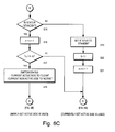
- Figures 6A, 6B and 6C is a flow diagram showing a method of operating the flow control module shown in Figure 2;
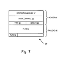
- Figure 7 illustrates a format of a message from the flow control module to the line interface shown in Figure 2; and
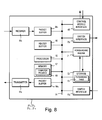
- Figure 8 is a schematic block diagram of the line interface module shown in Figure 2;
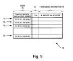
- Figure 9 illustrates a forwarding table provided in a line interface module;
- Figure 10 is a flow diagram showing a method of operating a line interface shown in Figure 2.
- Referring to Figure 1, a
system 1 of networks includes anetwork node 2 in accordance with the present invention. In this example, thenetwork node 2 is an edge router. However, thenetwork node 2 may be core router. Furthermore, thenetwork node 2 need not be router, but may be, for example, a switch. - The
network node 2 is connected to adata network 3, such as the Internet, which provides access to services provided by, for example, web severs 41, 42, 43, astreaming sever 5 and a video-on-demand server 6. - The
network node 2 is connected to Internet-side connectivity terminators physical channels customer premises equipment user sites interfaces optical line terminator 8 and a WiMAX (i.e. conforming to IEEE 802.16)base station 9. Other types of connectivity may be used, such as cable modems. Also, only oneuser site - Users may access services, via
interfaces television set network node 2 may be connected to an authentication, authorization and accounting (AAA)server 20 to authenticate users who access the Internet. - Referring to Figure 2, the
network node 2 is shown in more detail. - The
network node 2 includes severalline interface modules control module 23, at least one flow control module 241, 242 and aninternal bus 25 connecting theline interface modules switch 22,control module 23 and the flow control module(s) 241, 242. - The
line interface modules layer 1" (also known as the "physical layer") connections, "layer 2" (also known as the "datalink layer") connections, such as Ethernet, and "layer 3" (also known as the "network layer"), such as Internet protocol (IP). Theswitching module 22 switches packets from one module to another, such as from oneline interface modules line interface module control module 23 managesother modules network node 2. Each flow control module 241, 242 collects and analyses information about received and transmitted packets and instructs theline interface module - When a
line interface module data packet 26, it decides how to deal with thepacket 26, such as whether it should drop or transfer thepacket 26. Theline interface module header 27 from thedata packet 26 and sends amessage 28 to a flow control module 241, 242. - Referring also to Figure 3, a format 28' of the
message 28 is shown in more detail. - The message format 28' includes a
header 30 and apayload 31. Theheader 30 includes adestination module field 32, asource module field 33, a receivedpacket type field 34 and a receivedpacket length field 35. Thepayload 31 includes aheader field 36 for storing the receivedpacket header 27. The received packet header may be in the form of a "layer 2" header, such as an Ethernet frame header, and/or the "layer 3" header, such as IP packet header. - As will be explained in more detail later, the flow control module 241, 242 records information about a flow of data packets, determines, for example, whether the number of packets for the flow exceeds a threshold value and, if so, sends an
message 29 to theline interface module message 29 to more than one (e.g. all) line interface module(s) 211, 212, ..., 21N. - Referring to Figure 4, the flow control module 241, 242 is shown in more detail.
- The flow control module 241, 242 includes a switch interface 371, 372, a header-sampling
unit 38, adata buffer 39,storage 40 for storing a statistics table 41, aprocessor 42,memory 43 for storing, among other things, computer programs(s) 44 and ancontrol module interface 45 for communicating with control module 45 (Figure 2). The switch interface 371, 372, header-samplingunit 38,data buffer 39,storage 40,processor 42,memory 43 andcontrol module interface 45 are interconnected by abus 46. Thecomputer program 44 which, when executed by the flow control module, causes the flow control module to provide flow control processes is stored in storage (not shown) and loaded intomemory 43 for execution by theprocessor 42. - When flow control module 241, 242 receives the message 28 (Figure 2), the message 28 (Figure 2) is stored in
buffer 39. The header-samplingunit 38 extracts flow information from the header 27 (Figure 2) stored in the received packet header field 36 (Figure 3). - Referring to Figure 5, the flow control table 41 is shown in greater detail.
- Each entry 471, 472, 473, ...47M in the table 41 (shown in Figure 5 as a row) includes a
respective field 48 for identifying a flow, in this example, using a source IP address and a destination IP address, such as 192.168.10.5, 192.168.20.2. Each entry 471, 472, 473, ...47M also includes a respective propertythreshold value field respective status field - The flow control table 41 includes first and second portions 51A, 51B (aslo referred to as "side A" and "side B" respectively). Each side 51A, 51B includes, for each entry 471, 472, 473, ...47M, a status field 52A1, 52A2, 52A3, ...,52AM, 52B1, 52B2, 52B3, ...,52BM, a flow property field 53A1, 53A2, 53A3, ...,53AM, 53B1, 53B2, 53B3, ...,53BM and a start time field 54A1, 54A2, 54A3, ...,54AM, 54B1, 54B2, 54B3, ...,54BM. The flow control table 41 may include more than two sides. For each entry 471, 472, 473, ...47M, a single start time field may be used.
- Each side 51A, 51B is used alternately to store information about a flow and swap after a predetermined period of time. As will be become clear later, the flows need not concurrently store information on the same side 51A, 51B, in other words one flow may record information on one side of the table, for example on side A (i.e. the first side 51A), and another flow may record information on the other side of the table, for example side B (i.e. the first side 51B).
- The status field 52A1, 52A2, 52A3, ...,52AM, 52B1, 52B2, 52B3, ...,52BM is used to indicate one of three conditions of each side 51A, 51B for each entry 471, 472, 473, ...47M, namely whether the side is in ACTIVE, STANDBY or CLEAR state using, for example (binary) codes "00", "01" and "10" respectively.
- When a side 51A, 51B is in the ACTIVE state, the value stored in its flow property field 53A1, 53A2, 53A3, ...,53AM, 53B1, 53B2 53B3, ...,53BM is used when comparing the flow property value with the threshold value.
- When a side 51A, 51B is in the STANDBY state, its flow property field 53A1, 53A2, 53A3, ...,53AM, 53B1, 53B2, 53B3, ...,53BM is used for accumulating flow information. Thus, each time information about a packet is received, the flow property field 53A1, 53A2, 53A3, ...,53AM, 53B1 53B2, 53B3, ...,53BM is updated.
- When a side 51A, 51B is in the CLEAR state, it is not used.
- A side 51A, 51B which is in an STANDBY or CLEAR state, it also defined as being in a NON-ACTIVE state.
- The start time field 54A1, 54A2, 54A3, ...,54AM, 54B1, 54B2, 54B3, ...,54BM is used to record the time at which the flow property field 53A1, 53A2, 53A3, ...,53AM, 53B1, 53B2, 53B3, ...,53BM begins collecting information. As will be explained later, this field is used to decide whether the sides 51A, 51B change state and, thus, swap roles. In this example, the start time field 54 A1, 54A2, 54A3, ...,54AM, 54B1, 54B2, 54B3, ...,54BM stores a timer value, for example expressed as a number (or integer number) of clock cycles or seconds. However, the start time field 54A1, 54A2, 54A3, ...,54AM, 54B1, 54B2, 54B3, ...,54BM can store a (formatted) clock time, such as Universal Time.
- Referring to Figures 4, 5 and 6A to 6C, a method of operating the flow control module 241, 242 will now be described.
- When the flow control module 241, 242 receives a message 28 (Figure 2), the header-sampling
unit 38 checks the received packet header 27 (Figure 2) and identifies a flow (step S1). Theprocessor 42 inspects the flow control table 41 to determine whether any of the entries 471, 472, 473, ...47M corresponds to the flow (step S2). - If the
processor 42 does not find a corresponding entry in the table 41, then it creates a new entry corresponding to the flow (for example, last entry 47M) (step S3) and places one side 51A, 51B (e.g. the first side 51A) in an ACTIVE state, while placing the other side (e.g. the second side 51B) in an STANDBY state (step S4). For the side 51B on STANDBY (in this case the second side 51B), theprocessor 42 stores a start time, t0, in the start time field, e.g. start time field 54BM (step S5) and updates the flow property value in the flow property value field, e.g. flow property value field 53B1, in this case by adding incrementing the stored value by one, i.e. n= n+1 (step S6). The procedure ends in respect of the receiveddata packet 28 and the flow control module 241, 242 waits for another message 28 (Figure 2). - If the
processor 42 finds an entry corresponding to the flow, for example a first entry 471, then it identifies the side 51A, 51B of the table 41 for the entry 471 which is in the ACTIVE state (step S7). For the purposes of illustration, it is assumed that the first side 51A is ACTIVE. Theprocessor 42 extracts the start time, t0, stored in the first time field 51A1, computes an elapsed time, t - t0, and compares the elapsed time with a first predetermined time interval, Td (step S8). - If the
processor 42 determines that elapsed time, t - t0 does not exceed the first predetermined time interval, Td, then the side currently indicated as being in the ACTIVE state (in this case, the first side 51A) is used for the immediately following steps. - Referring in particular to Figures 4 and 6B, the
processor 42 compares the elapsed time with a second predetermined time interval, Tm, (which is less than the first predetermined time interval, Td, i.e. Tm < Td ) to determine whether a long enough interval has passed for a representative amount of information to be gathered (step S9). - If the
processor 42 determines that the elapsed time, t - t0 exceeds the second predetermined time interval, Tm, then theprocessor 42 extracts a property value (in this example the number of data packets received, n) from the property value field, e.g. property value field 53A1, on the side currently indicated as being in the ACTIVE state, calculates an average value (in this case n/ t - t0) and compares the average rate to the threshold value, e.g. whether Nt < n/ t - t0 (step S10). - If the
processor 42 determines that the average value exceeds the threshold value, then it sets the flag in the status field,e.g. status field 501, for the entry to indicate that the threshold value has been exceeded, e.g. by setting the flag to "1" (step S11). Otherwise, if theprocessor 42 determines that the average value does not exceed the threshold value, then it sets the flag to indicate that the threshold value has not been exceeded, e.g. by setting the flag to "0" (step S12). - The
processor 42 determines whether the state of the flag in the status field, e.g.field 501, has changed (step S13). If theprocessor 42 determines that the flag state has changed, then it returns a message 29 (Figure 2) to theline interface module data packet 28 and the flow control module 241, 242 waits for another message 28 (Figure 2). - Referring to Figure 7, a format 29' of the
message 29 is shown in greater detail. - The message format 29' includes a
header 55 and apayload 56. Theheader 55 includes adestination module field 57, asource module field 58, a receivedpacket type field 59 and a receivedpacket length field 60. Thepayload 56 includes aflow field 61 for storing the identity of the flow, e.g.first flow 481, in this example in the form of the source and destination IP addresses, and aflag field 61 for storing the flag, e.g. corresponding 501. - Referring to Figures 4 and 6A, at step S8, if the
processor 42 determines that the elapsed time, t - t0 exceeds the first predetermined time interval, Td, then the side not currently indicated as being ACTIVE (in this case, the second side 51A) is used when performing the following steps. - Referring to Figures 4 and 6C, the
processor 42 identifies whether the NON-ACTIVE side is in a STANDBY state (step S15). - If the
processor 42 identifies that the NON-ACTIVE side is in a STANDBY state, then it updates the value in the flow property field, e.g. flow property field 53A1, in this case by incrementing the stored value by one, i.e. n = n+1 (step S16). - The
processor 42 compares the elapsed time with the second predetermined time interval, Tm (step S17). - If the
processor 42 determines that elapsed time, t - t0, exceeds the second (longer) predetermined time interval, Tm, then theprocessor 42 clears the property value and start time fields, e.g. property value and start time fields 53A1, 54A1, on the currently ACTIVE side, e.g.first side first side 50A, to CLEAR and the status field, e.g. second status field 52B1, on the currently NON-ACTIVE side, e.g. second side 51B, to ACTIVE (step S18). Thus, the newly set ACTIVE side (in this example, second side 51B) for the entry is used for comparing the flow property value with the threshold value. - If, at step S17, the
processor 42 determines that not enough time has elapsed since starting to accumulate information (i.e. t - t0 < Tm), then the currently ACTIVE side, e.g. the first side 51A, is still used for comparing the flow property value with the threshold value. - If, at
step 15, theprocessor 42 identifies that the NON-ACTIVE side, e.g. second side 51B, is not in the STANDBY state (i.e. in the CLEAR state), then it sets the value in the status field, in this case status field 52B1, on the NON-ACTIVE side to STANDBY (step S19). On the NON-ACTIVE side, in this case the second side 51B, theprocessor 42 stores a start time, t0, in the start time field, e.g. start time field 54B1 (step S20) and updates the value in the flow property field, e.g. flow property field 53B1, by incrementing the stored value by one, i.e. n = n+1 (step S21). - Once an ACTIVE side for an entry has been set in steps S17 & S18 or left unchanged in step S17 or steps S19 to S21, the
processor 42 carries out steps S9 to S14, as described earlier. - Values of the first and second predetermined time intervals, Td and Tm, and the threshold value Nt may be decided by an operator. For example, the operator may decide that a user broadcasting packets for more than 10 minutes at a rate of approximately 10 Mbit/s may be excessive and lead to network congestion. Thus, values of the first and second predetermined time intervals, Td and Tm, may be 60 s and 600 s respectively, and the threshold value Nt may be 75000 (packets), assuming a packet is 1 kB.
- Referring to Figure 8, a
line interface module - Each
line interface module control module interface 65, aprocessor 66,memory 67 for storing, among other things, computer programs(s) 68, aheader buffer 69, a switch interface 701, 702, a forwardingengine 71 and astorage 72 for storing a forwarding table 73. Abus 74 connects the received packet buffer 641, transmission packet buffer 642,control module interface 65,processor 66,memory 67,header buffer 69, switch interface 70, forwardingengine 71 andstorage 72. The packet receiver 631 feed packets into the received packet buffer 641 and the transmission packet buffer 642 feeds packets into the packet transmitter 632. - The packet receiver 631 and packet transmitter 632 terminate (OSI) "
layer 1" and "layer 2" connections for received and transmitted packets respectively. As will be explained in more detail later, when theline interface module header buffer 69 and the forwardingengine 71 searches the forwarding table 73 to find an output port for thepacket 26. Theprocessor 66 prepares the message 29 (Figure 2) using the header 27 (Figure 2) stored in theheader buffer 69. - Referring to Figure 9, the forwarding table 73 is shown in further detail.
- Each
entry respective field 76 for identifying a flow, in this example, using a source IP address and a destination IP address. Eachentry status field 76 for showing whether the flow exceeds its thresholds and a forwardinginformation field 77, for example using a next hop IP address and output interface module identifier. Thestatus field 76 is set when an indication message 29 (Figure 2) is received from the flow control module 241, 242 (Figure 2). - Referring to Figures 8 and 9, the forwarding
engine 71 searches the forwarding table 73 to find an entry corresponding to a receivedpacket 26. If thestatus field 76 is set to indicate (for example by the flag "1") that the packet can be dropped, then the forwardingengine 71 drops thepacket 26 stored in the packet buffer 641, 642. Otherwise, if thestatus field 76 is set to indicate (for example by the flag "0") that thepacket 26 can be forwarded, the forwardingengine 71 transfers thepacket 26 in accordance with the information stored in the corresponding forwardinginformation field 77. - Referring to Figures 8, 9 and 10, a method of operating a
line interface module - When a
message 29 is received from the flow control module 241, 242 (step S22), theprocessor 69 inspects the forwarding table 73 to determine whether an entry exists corresponding to the flow (step S23). - If the
processor 69 finds anentry - If the
processor 69 does not find a corresponding entry, then it creates a new one in the forwarding table 73 (step S25) and sets the flag in thestatus field 76 according to the message 29 (step S26). - It will be appreciated that many modifications may be made to the embodiments hereinbefore described. For example, the flow control module may send a message regardless of whether there is a change of state.
Claims (25)
Priority Applications (2)
| Application Number | Priority Date | Filing Date | Title |
|---|---|---|---|
| DE602006012968T DE602006012968D1 (en) | 2006-08-09 | 2006-08-09 | Arrangement for flow control of data packets |
| EP06118695A EP1887741B1 (en) | 2006-08-09 | 2006-08-09 | Apparatus for controlling data packet flow |
Applications Claiming Priority (1)
| Application Number | Priority Date | Filing Date | Title |
|---|---|---|---|
| EP06118695A EP1887741B1 (en) | 2006-08-09 | 2006-08-09 | Apparatus for controlling data packet flow |
Publications (2)
| Publication Number | Publication Date |
|---|---|
| EP1887741A1 true EP1887741A1 (en) | 2008-02-13 |
| EP1887741B1 EP1887741B1 (en) | 2010-03-17 |
Family
ID=37057168
Family Applications (1)
| Application Number | Title | Priority Date | Filing Date |
|---|---|---|---|
| EP06118695A Not-in-force EP1887741B1 (en) | 2006-08-09 | 2006-08-09 | Apparatus for controlling data packet flow |
Country Status (2)
| Country | Link |
|---|---|
| EP (1) | EP1887741B1 (en) |
| DE (1) | DE602006012968D1 (en) |
Cited By (4)
| Publication number | Priority date | Publication date | Assignee | Title |
|---|---|---|---|---|
| US20110202658A1 (en) * | 2010-02-18 | 2011-08-18 | Hitachi, Ltd. | Information system, apparatus and method |
| US9253035B2 (en) | 2013-02-21 | 2016-02-02 | International Business Machines Corporation | Reducing switch state size in flow-based networks |
| RU2656706C1 (en) * | 2014-05-01 | 2018-06-06 | Нек Корпорейшн | Communication device, control device, communication system, method of processing of receiving package, communication device control method and program |
| CN115202737A (en) * | 2021-04-14 | 2022-10-18 | 澜起科技股份有限公司 | Apparatus and method for selecting a maximum value |
Families Citing this family (1)
| Publication number | Priority date | Publication date | Assignee | Title |
|---|---|---|---|---|
| US9407557B2 (en) * | 2012-12-22 | 2016-08-02 | Edgewater Networks, Inc. | Methods and systems to split equipment control between local and remote processing units |
Citations (6)
| Publication number | Priority date | Publication date | Assignee | Title |
|---|---|---|---|---|
| WO1999057825A1 (en) | 1998-05-04 | 1999-11-11 | Cabletron Systems, Inc. | A method and apparatus for controlling the flow of variable-length packets through a multiport switch |
| EP1119142A2 (en) * | 2000-01-19 | 2001-07-25 | NEC Corporation | Network node with a queue for long messages |
| US20030002438A1 (en) * | 2001-07-02 | 2003-01-02 | Hitachi, Ltd. | Packet forwarding apparatus with packet controlling functions |
| US20030012197A1 (en) * | 2001-07-02 | 2003-01-16 | Hitachi, Ltd. | Packet transfer apparatus with the function of flow detection and flow management method |
| US20040136368A1 (en) | 2003-01-14 | 2004-07-15 | Koji Wakayama | Method of transmitting packets and apparatus of transmitting packets |
| US6798746B1 (en) * | 1999-12-18 | 2004-09-28 | Cisco Technology, Inc. | Method and apparatus for implementing a quality of service policy in a data communications network |
-
2006
- 2006-08-09 DE DE602006012968T patent/DE602006012968D1/en active Active
- 2006-08-09 EP EP06118695A patent/EP1887741B1/en not_active Not-in-force
Patent Citations (6)
| Publication number | Priority date | Publication date | Assignee | Title |
|---|---|---|---|---|
| WO1999057825A1 (en) | 1998-05-04 | 1999-11-11 | Cabletron Systems, Inc. | A method and apparatus for controlling the flow of variable-length packets through a multiport switch |
| US6798746B1 (en) * | 1999-12-18 | 2004-09-28 | Cisco Technology, Inc. | Method and apparatus for implementing a quality of service policy in a data communications network |
| EP1119142A2 (en) * | 2000-01-19 | 2001-07-25 | NEC Corporation | Network node with a queue for long messages |
| US20030002438A1 (en) * | 2001-07-02 | 2003-01-02 | Hitachi, Ltd. | Packet forwarding apparatus with packet controlling functions |
| US20030012197A1 (en) * | 2001-07-02 | 2003-01-16 | Hitachi, Ltd. | Packet transfer apparatus with the function of flow detection and flow management method |
| US20040136368A1 (en) | 2003-01-14 | 2004-07-15 | Koji Wakayama | Method of transmitting packets and apparatus of transmitting packets |
Cited By (7)
| Publication number | Priority date | Publication date | Assignee | Title |
|---|---|---|---|---|
| US20110202658A1 (en) * | 2010-02-18 | 2011-08-18 | Hitachi, Ltd. | Information system, apparatus and method |
| EP2362606A1 (en) * | 2010-02-18 | 2011-08-31 | Hitachi Ltd. | Information system, apparatus and method |
| US8782239B2 (en) * | 2010-02-18 | 2014-07-15 | Hitachi, Ltd. | Distributed router computing at network nodes |
| US9253035B2 (en) | 2013-02-21 | 2016-02-02 | International Business Machines Corporation | Reducing switch state size in flow-based networks |
| RU2656706C1 (en) * | 2014-05-01 | 2018-06-06 | Нек Корпорейшн | Communication device, control device, communication system, method of processing of receiving package, communication device control method and program |
| US10686712B2 (en) | 2014-05-01 | 2020-06-16 | Nec Corporation | Communication apparatus, control apparatus, communication system, received packet processing method, communication apparatus control method, and program |
| CN115202737A (en) * | 2021-04-14 | 2022-10-18 | 澜起科技股份有限公司 | Apparatus and method for selecting a maximum value |
Also Published As
| Publication number | Publication date |
|---|---|
| DE602006012968D1 (en) | 2010-04-29 |
| EP1887741B1 (en) | 2010-03-17 |
Similar Documents
| Publication | Publication Date | Title |
|---|---|---|
| US7200116B2 (en) | Communication device and method, and system | |
| US8320242B2 (en) | Active response communications network tap | |
| US10230788B2 (en) | System and method for selecting a content delivery network | |
| US8468590B2 (en) | Rate limiting data traffic in a network | |
| US7606147B2 (en) | Application aware traffic shaping service node positioned between the access and core networks | |
| US12003407B2 (en) | Resource usage in a multipath network | |
| CN102474463B (en) | Communication device and communication method | |
| US5781532A (en) | Data link interface for packet-switched network | |
| US20030108063A1 (en) | System and method for aggregating multiple information channels across a network | |
| US20030037159A1 (en) | Timer rollover handling mechanism for traffic policing | |
| JP4988632B2 (en) | Packet relay device and traffic monitoring system | |
| CN110300431A (en) | A kind of data traffic processing method and related network device | |
| KR20130023094A (en) | Dynamic bandwidth re-allocation | |
| US8315245B2 (en) | Overload call control in a VoIP network | |
| WO2007036786A2 (en) | Application layer metrics monitoring | |
| EP1887741B1 (en) | Apparatus for controlling data packet flow | |
| US8964766B2 (en) | Session relay equipment and session relay method | |
| EP1971087A1 (en) | Method for controlling data traffic between gateways | |
| JP4678652B2 (en) | P2P traffic monitoring control apparatus and method | |
| JP4580111B2 (en) | Network system | |
| WO2006027380A1 (en) | A device and method for multicasting packets in a subscriber network | |
| JPWO2004064341A1 (en) | Non-instantaneous transfer method in case of line failure in IP network | |
| US7414984B2 (en) | System and method for efficient addition of network resources | |
| EP3131344A1 (en) | Method and system for discovery of access aggregation points for bonding approaches in a telecommunication network | |
| EP3809798A1 (en) | Communication system comprising an interconnection network and a plurality of radio sites interconnected via the interconnection network |
Legal Events
| Date | Code | Title | Description |
|---|---|---|---|
| PUAI | Public reference made under article 153(3) epc to a published international application that has entered the european phase |
Free format text: ORIGINAL CODE: 0009012 |
|
| AK | Designated contracting states |
Kind code of ref document: A1 Designated state(s): AT BE BG CH CY CZ DE DK EE ES FI FR GB GR HU IE IS IT LI LT LU LV MC NL PL PT RO SE SI SK TR |
|
| AX | Request for extension of the european patent |
Extension state: AL BA HR MK YU |
|
| 17P | Request for examination filed |
Effective date: 20080430 |
|
| 17Q | First examination report despatched |
Effective date: 20080603 |
|
| AKX | Designation fees paid |
Designated state(s): DE FR GB |
|
| GRAP | Despatch of communication of intention to grant a patent |
Free format text: ORIGINAL CODE: EPIDOSNIGR1 |
|
| GRAS | Grant fee paid |
Free format text: ORIGINAL CODE: EPIDOSNIGR3 |
|
| GRAA | (expected) grant |
Free format text: ORIGINAL CODE: 0009210 |
|
| AK | Designated contracting states |
Kind code of ref document: B1 Designated state(s): DE FR GB |
|
| REG | Reference to a national code |
Ref country code: GB Ref legal event code: FG4D |
|
| REF | Corresponds to: |
Ref document number: 602006012968 Country of ref document: DE Date of ref document: 20100429 Kind code of ref document: P |
|
| PLBE | No opposition filed within time limit |
Free format text: ORIGINAL CODE: 0009261 |
|
| STAA | Information on the status of an ep patent application or granted ep patent |
Free format text: STATUS: NO OPPOSITION FILED WITHIN TIME LIMIT |
|
| 26N | No opposition filed |
Effective date: 20101220 |
|
| REG | Reference to a national code |
Ref country code: FR Ref legal event code: PLFP Year of fee payment: 10 |
|
| PGFP | Annual fee paid to national office [announced via postgrant information from national office to epo] |
Ref country code: GB Payment date: 20150805 Year of fee payment: 10 Ref country code: DE Payment date: 20150804 Year of fee payment: 10 |
|
| PGFP | Annual fee paid to national office [announced via postgrant information from national office to epo] |
Ref country code: FR Payment date: 20150629 Year of fee payment: 10 |
|
| REG | Reference to a national code |
Ref country code: DE Ref legal event code: R119 Ref document number: 602006012968 Country of ref document: DE |
|
| GBPC | Gb: european patent ceased through non-payment of renewal fee |
Effective date: 20160809 |
|
| REG | Reference to a national code |
Ref country code: FR Ref legal event code: ST Effective date: 20170428 |
|
| PG25 | Lapsed in a contracting state [announced via postgrant information from national office to epo] |
Ref country code: DE Free format text: LAPSE BECAUSE OF NON-PAYMENT OF DUE FEES Effective date: 20170301 Ref country code: FR Free format text: LAPSE BECAUSE OF NON-PAYMENT OF DUE FEES Effective date: 20160831 Ref country code: GB Free format text: LAPSE BECAUSE OF NON-PAYMENT OF DUE FEES Effective date: 20160809 |