EP1887684A1 - Motor driving control method and motor driving control apparatus - Google Patents
Motor driving control method and motor driving control apparatus Download PDFInfo
- Publication number
- EP1887684A1 EP1887684A1 EP06756924A EP06756924A EP1887684A1 EP 1887684 A1 EP1887684 A1 EP 1887684A1 EP 06756924 A EP06756924 A EP 06756924A EP 06756924 A EP06756924 A EP 06756924A EP 1887684 A1 EP1887684 A1 EP 1887684A1
- Authority
- EP
- European Patent Office
- Prior art keywords
- steering
- motor
- phase
- angular velocity
- current
- Prior art date
- Legal status (The legal status is an assumption and is not a legal conclusion. Google has not performed a legal analysis and makes no representation as to the accuracy of the status listed.)
- Withdrawn
Links
Images







Classifications
-
- B—PERFORMING OPERATIONS; TRANSPORTING
- B62—LAND VEHICLES FOR TRAVELLING OTHERWISE THAN ON RAILS
- B62D—MOTOR VEHICLES; TRAILERS
- B62D5/00—Power-assisted or power-driven steering
- B62D5/04—Power-assisted or power-driven steering electrical, e.g. using an electric servo-motor connected to, or forming part of, the steering gear
- B62D5/0457—Power-assisted or power-driven steering electrical, e.g. using an electric servo-motor connected to, or forming part of, the steering gear characterised by control features of the drive means as such
- B62D5/046—Controlling the motor
Definitions
- the present invention relates to a motor driving control method and a motor driving control apparatus for drivingly controlling a three-phase brushless motor which is provided in a vehicle for steering assist, in dependence on a steering angle, a vehicle speed and other driving states.
- a microcomputer 1 determines a command value Iq1* of motor drive current in dependence on a driving state, and in dependence on the command value Iq1*, an inverter control circuit 2 performs ON/OFF controls of respective switches UH, UL, VH, VL, WH, WL of a three-phase bridge circuit 3, whereby three-phase alternating currents as motor drive current are applied from the three-phase bridge circuit 3 to a three-phase brushless motor 4 for steering assist.
- shunt resistances R1, R2, R3 are connected in series to the switches UL, VL, WL at a lower stage of the three-phase bridge circuit 3, and current-feedback control is performed by detecting an actual motor drive current based on inter-terminal voltages of these shunt resistances R1, R2, R3.
- Patent Document 1 Japanese unexamined, published patent application No. 2004-117070 ( Figure 1 )
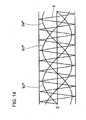
- the aforementioned inverter control circuit 2 determines the timings to turn ON/OFF the respective switches UH, UL, ⁇ in the triangle comparison method. That is, based on the command value Iq1* of the motor drive current, three-phase alternating current command waves Vu*, Vv*, Vw * shown in Figure 14 are generated and compared with a triangle wave K (generally called "transfer wave” or "carry wave”) , and ON/OFF timings for the switches UH, UL, ⁇ are determined from the intersection points of the three-phase alternating current command waves Vu*, Vv*, Vw* with the triangle wave K, as shown in Figure 15 .
- a triangle wave K generally called "transfer wave” or "carry wave”
- the cycle of the triangle wave K is set to be extremely short compared with the cycle of the three-phase alternating current command waves Vu*, Vv*, Vw*, and in Figures 14 and 15 , the cycle of the triangle wave K is drawn as being sufficiently longer than the actual cycle in order to schematically show the three-phase alternating current command waves Vu*, Vv*, Vw* and the triangle wave K. Further, in Figure 15 , the three-phase alternating current command waves Vu*, Vv*, Vw* are partially enlarged and are represented by lines for simplicity.
- the current detection for current-feedback control is performed at the timing that the triangle wave K reaches its peak point. This is for the reason that the timing at which the triangle wave K reaches the peak point is the hardest to suffer the influence of switching noise.
- the switches UH, UL, ⁇ take a time to switch completely from an ON state to an OFF state.
- a predetermined dead time T1 has to be provided between the timing at which of the switches at both of the upper and lower stages, those in the ON state start to become OFF and the timing at which those in the OFF state start to become ON.
- the peak level of each of the three-phase alternating current command waves Vu*, Vv*, Vw* (Vu* only is exemplified in Figure 16 ) has heretofore been limited so that the distance between a pair of intersection points P1, P1 of a peak area of each three-phase alternating current command wave Vu*, Vv*, Vw* with a peak point neighborhood of the triangle wave K becomes equal to or longer than the sum (T3 in the same figure) of a current detection time T2 by the shunt resistances R1, R2, R3 and a dead time T1.
- the maximum value of the duty ration (r) in the PWM control has heretofore been limited to a value calculated by the following expression. That is, in the prior art, the output of a direct current power supply 5 (refer to Figure 13 ) connected to the three-phase bridge circuit 3 has not been utilized effectively.
- the present invention has been made taking the foregoing circumstances into consideration, and an object thereof is to provide a motor driving control method and a motor driving control apparatus capable of effectively utilizing a direct current power supply connected to a three-phase bridge circuit.
- a motor driving control method for applying three-phase alternating currents as motor drive current from a three-phase bridge circuit to a three-phase brushless motor provided in a vehicle for steering assist, by performing PWM control in a triangle comparison method based on a command value determined in dependence on a steering angle, a vehicle speed and other driving states and for performing current-feedback control with actual motor drive currents detected by shunt resistances, the motor driving control method being characterized in that when a steering angular velocity is lower than a predetermined reference angular velocity, actual motor drive currents are detected by the respective shunt resistances with the peak level of each of three-phase alternating current command waves being limited so that the interval between a pair of intersection points of a peak area of each of the three-phase alternating current command waves with a peak point neighborhood of the triangle wave which waves are compared in the triangle comparison method is made to be longer than the sum of a current detection time by the shut resistances and
- a motor driving control apparatus is a motor driving control apparatus which comprises a three-phase bridge circuit connected to a three-phase brushless motor provided in a vehicle for steering assist, a motor control circuit for making the three-phase bridge circuit output three-phase alternating currents as motor drive current, by performing PWM control in a triangle comparison method based on a command value determined in dependence on a steering angle, a vehicle speed and other driving states, and shunt resistances for providing current-feedback of the motor drive current, the motor driving control apparatus being characterized in that steering state judgment means is further provided for judging whether the steering manipulation is at the time of an ordinary steering in which the steering angular velocity is lower than a predetermined reference steering angular velocity or at the time of a quick steering in which the steering angular velocity is higher than the reference steering angular velocity, that at the time of the ordinary steering, the motor control circuit detects actual motor drive currents by the respective shunt resistances with the peak level of each of the three-phase alternating current command waves being limited
- the invention according to Claim 3 is characterized in that in the motor driving control apparatus as set forth in Claim 2, output voltage judgment means is further provided for judging whether or not, the output voltage from a direct current power supply provided in the vehicle to the three-phase bridge circuit is higher than a predetermined reference output voltage and that the motor control circuit mitigates the limitation on the peak level of each of the three-phase alternating current waves under the condition that the output voltage of the direct current power supply is higher than the reference output voltage.
- the invention according to Claim 4 is characterized in that in the motor driving control apparatus as set forth in Claim 2 or 3, engine rotational speed judgment means is further provided for judging whether or not, the rotational speed of an engine provided in the vehicle is higher than a predetermined reference rotational speed and that the motor control circuit mitigates the limitation on the peak level of each of the three-phase alternating current waves under the condition that the rotational speed of the engine is higher than the reference rotational speed.
- the current detections by the shunt resistances becomes possible by limiting the peak level of each of the three-phase alternating current command waves so that the interval between the pair of intersection points of the peak area of each of the three-phase alternating current command waves with the peak point neighborhood of the triangle wave which waves are compared in the triangle comparison method is made to be longer than the sum of the current detection time by the shut resistances and the dead time for switching.
- the peak level of each of the three-phase alternating current command waves can be raised to the level that the interval between the pair of intersection points of the peak area of each of the three-phase alternating current command waves with the peak point neighborhood of the triangle wave becomes approximately the same length as the dead time. That is, it can be realized to heighten the duty ratio in the PWM control. Therefore, the output power of the direct current power supply connected to the three-phase bridge circuit can be utilized effectively, and hence, it can be realized to increase the power supply quantity to the three-phase brushless motor.
- the direct current power supply is supplied with electricity from the engine while the power supply quantity to the three-phase brushless motor is increased, and therefore, it can be realized to prevent the output power of the direct current power supply from decreasing.
- a vehicle 10 shown in Figure 1 is provided with an electric power steering system 11 and is capable of steering steered wheels 12, 12 by assisting the steering manipulation by the driver by a three-phase brushless motor 19 (hereafter referred to simply as "motor 19").
- a three-phase brushless motor 19 hereafter referred to simply as "motor 19"
- an inter-steered wheel shaft 16 is arranged between a pair of the steered wheels 12, 12, and the inter-steered wheel shaft 16 passes through a sleeve housing 18.
- Opposite ends of the inter-steered wheel shaft 16 are connected to the respective steered wheels 12, 12 through tie rods 17, 17, and the sleeve housing 18 is secured to a body of the vehicle 10.
- the sleeve housing 18 is provided at an axially middle portion thereof with a large-diameter portion 18D, in which the motor 19 is built.
- the motor 19 is composed of a stator 20 which is inserted and secured to the internal surface of the sleeve housing 18, and a sleeve-like rotor 21 loosely inserted inside the stator 20. Then, the inter-steered wheel shaft 16 passes through the rotor 21.
- the large-diameter portion 18D of the sleeve housing 18 is provided at its one end with a motor rotational angle sensor 25 (e.g., resolver) for detecting the rotational position of the rotor 21.
- a motor rotational angle sensor 25 e.g., resolver
- a ball screw nut 22 is assembled in the internal surface of the rotor 21. Further, a ball screw portion 23 is formed on a middle portion in the axial direction of the inter-steered wheel shaft 16.
- the ball screw nut 22 and the ball screw portion 23 constitute a ball screw mechanism 24, so that when the ball screw nut 22 is rotated together with the rotor 21, the ball screw portion 23 is moved linearly with respect to the sleeve housing 18 to steer the steered wheels 12, 12.
- a rack 30 is formed and is in meshing with a pinion 31 provided at a lower end of a steering shaft 32.
- a steering wheel 33 is attached to an upper end of the steering shaft 32.
- the steering shaft 32 has attached thereto a steering angle sensor 34 and a torque sensor 35, which respectively detect the steering angle ⁇ 2 of the steering wheel and the load torque Tf exerted on the steering shaft 32. Further, a vehicle speed sensor 36 for detecting the vehicle speed V based on rotation of the steered wheel 12 is provided close to that steered wheel 12.
- the motor 19 is drivingly controllable by a motor driving control apparatus 40.
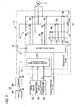
- the motor driving control apparatus 40 has a three-phase bridge circuit 43 and a motor control circuit 44.
- the motor control circuit 44 is composed of a command value determination section 41 and an inverter control section 42.
- the three-phase bridge circuit 43 is provided with three phase circuits 43U, 43V, 43W corresponding to coils for a U-phase, a V-phase and a W-phase of the motor 19. Further, a direct current power supply 14 is constituted by connecting a booster circuit 39 to a battery 38 and boosts the output voltage of the battery 38 by the booster circuit 39 to apply the boosted voltage to the three-phase bridge circuit 43. Further, the battery 38 receives electricity from an alternator (not shown) which is operated together with an engine.
- an upper stage switch UH, a lower stage switch UL and a shunt resistance Ru are connected in series in turn from the side of a connection point with a positive electrode of the direct current power supply 14.
- a U-phase coil in the motor 19 is connected to a common connection portion between both of the switches UH, UL.
- an upper stage switch VH, a lower stage switch VL and a shunt resistance Rv are connected in series, and a V-phase coil in the motor 19 is connected.
- an upper stage switch WH, a lower stage switch WL and a shunt resistance Rw are connected in series, and a W-phase coil in the motor 19 is connected.
- the switches UH, UL, WH, ⁇ in the three-phase bridge circuit 43 are all constituted by N-channel MOSFETs, gate terminals of which are connected to the inverter control section 42 of the motor control circuit 44. Further, terminal-to-terminal voltages of the shunt resistances Ru, Rv, Rw are inputted to the inverter control section 42 through amplifiers 44P, 44P, 44P provided in the motor control circuit 44. Further, the inverter control section 42 has also inputted thereto electric potentials at median points of the phase circuits 43U, 43V, 43W of the three-phase bridge circuit 43 (i.e., at the connection points of the phase circuits 43U, 43V, 43W with the respective phase coils of the motor 19).
- the command value determination section 41 is represented in the form of a control block diagram in Figure 3 . As shown in the figure, the command value determination section 41 receives respective detection results (load torque Tf, steering angle ⁇ 2 of steering wheel and vehicle speed V) from the torque sensor 35, the steering angle sensor 34 and the vehicle speed sensor 36 and determines a command value Iq1* of the motor drive current. Specifically, an assist command value calculation section 41 E determines an assist current command value Ix depending on the load torque Tf, based on the load torque Tf and a torque-current command value map (not shown).
- the aforementioned torque-current command value map is set to make the assist current command value Ix increase as the load torque Tf increases, for example.
- an increment of the load torque Tf can be cancelled by an assist torque which the motor 19 generates in dependence on the assist current command value lx, and hence, the driver is enabled to perform a steering manipulation while feeling a stable steering reaction force regardless of the friction coefficient of the road surface.
- the aforementioned steering angular velocity-current command value map is set to make the damper current command value Iy increase as the steering angular velocity increases. Since the damper current command value ly is subtracted from the assist current command value lx, there can be achieved a damper effect that the steering resistance becomes larger upon a quick steering manipulation.
- the vehicle speed-gain map is set to make the gain G1 smaller as the vehicle speed V increases.
- the assist torque by the motor 19 is decreased as the vehicle speed V increases, so that the quick steering manipulation is suppressed during a high speed traveling, whereas the vehicle 10 is enabled to make a large turn with a light steering manipulation during a slow speed traveling.
- the inverter control section 42 receives a command value Iq1* of the motor drive current from the command value determination section 41 and performs ON/OFF drives of the switches UH, UL, VH, ⁇ of the three-phase bridge circuit 43.
- the inverter control section 42 is configured as shown in the form of a control block diagram in Figure 4 . Further, the inverter control section 42 takes the command value Iq1* inputted from the command value determination section 41 as a command value for the q-axis current and processes a command value Id1* for the d-axis current as "0".
- a q-axis current controller 45q calculates a q-axis applying voltage Vq1 * from the difference between the q-axis current command value Iq1* and an actual q-axis current Iq2 referred to later.
- a d-q inverter 46 performs a d-q inversion of the applying voltages Vq1 *, Vd1 * to the q-axis and the d-axis and generates three-phase alternating current waves Vu1*, Vv1*, Vw1* shown in Figure 5(A) .
- a triangle wave comparator section 47 generates a triangle wave K shown in Figure 5(A) . As shown in Figure 6 , the triangle wave comparator section 47 determines ON/OFF timings for the switches UH, UL, VH, ⁇ from intersection points of the three-phase alternating current waves Vu1*, Vv1*, Vw1 * with the triangle wave K and performs ON/OFF drives of the switches UH, UL, VH, ⁇ .
- a pulse wave Vun shown in Figure 5(B) is applied between both terminals of the U-phase coil in the motor 19
- a pulse wave Vvn shown in Figure 5(C) is applied between both terminals of the V-phase coil
- a pulse wave Vwn shown in Figure 5(D) is applied between both terminals of the W-phase coil.
- Vun, Vvn are converted into a voltage between both terminals of a series circuit including the U-phase coil and the V-phase coil, it becomes a pulse wave Vuv the pulse width of which successively varies to follow the sine wave as shown in Figure 5(E) .
- a voltage between both terminals of a series circuit including the V-phase coil and the W-phase coil and a voltage between both terminals of a series circuit including the W-phase coil and the U-phase coil become pulse waves Vvw and Vwu to follow the sine waves as shown in Figures 5(F) and 5(G) .
- three-phase alternating currents comprising sine waves which are shifted 120 degrees from one another in phase in correspondence to these pulses waves Vuv, Vvw and Wwu are applied to the motor 19.
- the inverter control section 42 performs PWM control to apply the three-phase alternating currents from the three-phase bridge circuit 43 to the motor 19.
- the inverter control section 42 has been preset with a first duty limiting valve C1 and a second duty limiting value C2 for PWM control.
- the first duty limiting valve C1 is applied by a limiting value selector switch 54 shown in Figure 4 to the triangle wave comparator section 47.
- the triangle wave comparator section 47 with the first duty limiting valve C1 applied thereto limits the duty ratio in the PWM control to the first duty limiting valve C1 or under.
- the triangle wave comparator section 47 determines the peak level of each three-phase alternating current wave Vu1*, Vv1*, Vw1* to a predetermined value L1 relative to the peak level of the triangle wave K so that the duty ratio (r) becomes to the first duty limiting valve C1 or under.
- the interval between the pair of intersection points P1 and P1 of a peak area of each three-phase alternating current wave Vu1*, Vv1 *, Vw1 * (Vu1 * only exemplified in Figure 7(A) ) with a peak point neighborhood of the triangle wave K becomes the sum (T3 in Figure 7(A) ) of a current detection time T2 by each shunt resistance Ru, Rv or Rw and a dead time T1 taken to switch each switch UH, UL, VH, ⁇ or longer.
- the limiting value selector switch 54 operates when a predetermined condition referred to later is satisfied, to apply the second duty limiting value C2 to the triangle wave comparator section 47.
- the second duty limiting value C2 is greater than the first duty limiting valve C1.
- the interval between the pair of intersection points P1 and P1 of the peak area of each three-phase alternating current wave Vu1*, Vv1 *, Vw1 * with the peak point neighborhood of the triangle wave K becomes approximately the same length as the dead time T1 taken to switch each switch UH, UL, VH, ⁇ .
- the inverter control section 42 detects phase currents through the shunt resistances Ru, Rv, Rw in the three-phase bridge circuit 43 and converts the phase currents into a q-axis current lq2 and a d-axis current ld2 by a d-q converter 48. Then, the q-axis current lq2 and the d-axis current ld2 are used for current-feedback control.
- the inverter control section 42 detects the phase currents based on the terminal-to-terminal voltages of the shunt resistances Ru, Rv, Rw at a timing when the triangle wave K reaches the mountain-side peak (i.e., at the timing when the influence by the noise caused by the ON/OFF operations of the switches UH, UL, VH, ⁇ is the least and when current is applied to all of the shunt resistances Ru, Rv, Rw).
- the inverter control section 42 stops current detections by the shunt resistances Ru, Rv, Rw and performs the current-feedback control using an inferred q-axis current lq3 and an inferred d-axis current ld3 which are inferred by an inference circuit 49.
- the inverter control section 42 detects electric potentials Vu, Vv, Vw at median points on respective phase circuits 43U, 43V, 43W in the three-phase bridge circuit 43 and performs three-phase/d-q conversion of these electric potentials Vu, Vv, Vw by the d-q converter 48 to calculate a q-axis voltage Vq2 and a d-axis voltage Vd2.
- the inference circuit 49 receives the q-axis voltage Vq2, the d-axis voltage Vd2 and the motor rotational angle ⁇ 7 detected by the motor rotational angle sensor 25 and calculates the inferred q-axis current Iq2 and the inferred d-axis current Id2 by the use of the following [expression 1].
- symbol ⁇ 7 denotes a time-differentiated value of the motor rotational angle ⁇ 7.
- symbols R, L and Ke respectively denote the sum of resistances of the phase circuits in the motor 19 and the wiring, an inductance of the coils of the motor 19 and a back electromotive voltage constant, and these parameters inherent in the motor 19 are stored in advance in a data table provided in the inverter control section 42.
- [Expression 1 ] can be derived from a known expression (refer to the following [Expression 2]) which is described in a reference entitled " Theory and Practice on AC Servomotor System” (Publisher: Sougou-Denshi, Authors: Hidehiko Sugimoto, Masato Koyama and Sinzoh Tamai), page 73 .
- Id ⁇ 2 Iq ⁇ 2 - R L ⁇ ⁇ 7 - ⁇ ⁇ 7 - R L [ Id ⁇ 2 Iq ⁇ 2 ] + 1 L [ Id ⁇ 2 Iq ⁇ 2 ] - 1 L [ 0 Eq ]
- current value selector switches 51, 52 are provided between an output part of the inference circuit 49 and an output part of the d-q converter 48. Ordinarily, these current value selector switches 51, 52 operate to select the q-axis current lq2 and the d-axis current ld2 calculated by the d-q converter 48 to provide current feedbacks.
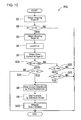
- the inverter control section 42 is provided with a CPU, a ROM and a RAM (all not shown) and judges whether the aforementioned predetermined condition is satisfied or not, by making the CPU execute a condition judgment program PG1 (shown in Figure 8 ) stored in the ROM at a predetermined cycle. Specifically, when executing the condition judgment program PG1, the inverter control section 42 obtains an engine rotational speed N1 (S1) and compares the speed N1 with a predetermined reference rotational speed Nk (S2: this step corresponds to "engine rotational speed judgment means" relating to the present invention).
- the inverter control section 42 obtains the steering angle ⁇ 2 from the steering angle sensor 34 (S3) and calculates a steering angular velocity ⁇ 2 by differentiating the steering angle ⁇ 2 with respect to time (S4).
- the inverter control section 42 obtains an output voltage E1 outputted from the direct current power supply 14 through a voltage circuit 53 (refer to Figure 2 ) provided in the motor driving control apparatus 40 (S6) and judges whether or not, the output voltage E1 is higher than a predetermined reference output voltage Ek (S7: this step corresponds to "output voltage judgment means” relating to the present invention).
- the inverter control section 42 stops the current detections by the shunt resistances Ru, Rv, Rw (S8) and instead, infers currents by the inference circuit 49 (S9).
- the inverter control section 42 alters the limiting value to be used for PWM control from the first duty limiting value C1 to the second duty limiting value C2 to mitigate the duty limitation (S10).
- the aforementioned condition is judged to have been satisfied if the engine rotational speed N1 is higher than the reference rotational speed Nk (S2: YES), if the steering angular velocity ⁇ 2 is greater than the reference angular velocity ⁇ k (S5: YES) and if the output voltage E1 is higher than the reference output voltage Ek (S7: YES).
- the inverter control section 42 operates the current value selector switches 51, 52 and the limiting value selector switch 54 and performs the PWM control with the use of the second duty control value C2 while performing the current-feedback control with the use of the inferred q-axis current lq3 and the inferred d-axis current ld3 which have been calculated by the inference circuit 49.
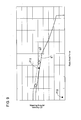
- the axial force of the rack 30 and the steering angular velocity ⁇ 2 become those values which as specified by a point P10 in the figure, are sufficiently lower than the critical values.
- the steering wheel 33 is quickly steered on a paved road surface to park the vehicle 10 for example, it may occur that as indicated by another point P11, they slightly exceed the critical values indicated by the critical property graph g1.
- the resistance to the steering manipulation of the steering wheel 33 would become excessively high beyond the aforementioned damper effect due to an insufficient output power of the motor 19.
- the actual motor drive currents (the inferred q-axis current Iq3 and the inferred d-axis current Id3) are inferred from the back electromotive voltage or the like in place of the current detections by the shunt resistances Ru, Rv, Rw, whereby the duty limiting value is changed from the first duty limiting value C1 to the second duty limiting value C2 to mitigate the limitation on the PWM control.
- the current applicable to the motor 19 can be increased to heighten the maximum allowable rotational speed of the motor 19. That is, when the steering wheel 33 is turned quickly, the critical values for the rack axial force and the steering angular speed w2 are heightened as being shifted from the critical property graph g1 to the critical property graph g2 in Figure 9 , so that it can be realized to overcome the deficiency in output power of the motor 19.
- the direct current power supply 14 can be preventing from falling in a deficiency of the output voltage.
- This embodiment differs from the first embodiment mainly with respect to the configuration of a condition judgment program PG2.
- PG2 condition judgment program
- a first reference output voltage Ek1, a second reference output voltage Ek2 and a third reference output voltage Ek3 are set as the reference output voltages to be compared with the output voltage E1 of the direct current power supply 14. These have a relation Ek1 ⁇ Ek2 ⁇ Ek3. Further, a first reference angular velocity ⁇ k1 and a second reference angular velocity ⁇ k2 are set as the values to be compared with the steering angular velocity ⁇ 2 and have a relation ⁇ k1 ⁇ ⁇ k2.
- condition judgment program PG2 when executed, a judgment is made of whether or not, the output voltage E1 from the direct current power supply 14 is a value between the first and second reference output voltages Ek1, Ek2 (S20).
- the direct current power supply 14 is judged to be in a normal output state, and the first reference angular velocity ⁇ k1 set for such normal output state is compared with the steering angular velocity ⁇ 2 (S21). Then, if the steering angular velocity w2 is higher than the first reference angular velocity ⁇ k1 (S21: YES), the processing from steps S8 to S10 is executed in the same manner as in the first embodiment to mitigate the limitation on the PWM control. As a consequence, the maximum output power of the motor 19 is increased when the steering wheel 33 is turned quickly in the normal output state of the direct current power supply 14. Therefore, the critical values for the rack axial force and the steering angular velocity ⁇ 2 can also be heightened as indicated as the change from the critical property graph g1 to the critical property graph g2 in Figure 11 .
- the output voltage E1 is not a value between the first and second reference output voltages Ek1, Ek2 (S20: NO)
- the output voltage E1 of the direct current power supply 14 becomes higher than that in the normal output state as a result that the booster circuit 39 boosts up the output of the battery 38 in the direct current power supply 14 which battery has been supplied with a sufficient electric supply from an alternator through a high speed rotation of the engine.
- the output voltage E1 is judged to be higher than the third reference output voltage Ek3 (S22: YES), and the second reference angular velocity ⁇ k2 set for such output state is compared with the steering angular velocity ⁇ 2 (S23).
- the steering angular velocity ⁇ 2 is judged to have become higher than the second reference angular velocity ⁇ k2 (S23: YES), and the processing from steps S8 to S10 is executed in the same manner as in the first embodiment to mitigate the limitation on the PWM control.
- the critical values for the rack axial force and the steering angular velocity ⁇ 2 can also be heightened as indicated as the change from a critical property graph g3 to another critical property graph g4 in Figure 11 .
- the shunt resistances Ru, Rv, Rw are connected in series to the respective phase circuits 43U, 43V, 43W in the three-phase bridge circuit 43
- the shunt resistances Ru, Rv, Rw may be connected in series between the respective phase circuits 43U, 43V, 43W in the three-phase bridge circuit 43 and the respective phase coils of the motor 19.
- the present invention may be applied to a motor driving control apparatus for a three-phase brushless motor which is provided in a steer-by-wire system or a variable transmission ratio steering system the transmission ratio of which is variable between a steering wheel and steered wheels.
- the motor 19 and the inter-steered wheel shaft 16 are connected by the ball screw mechanism 24, a mechanism for connecting the motor 19 to the steering train is not limited to such a ball screw mechanism. Therefore, there can be taken any of a construction that the motor 19 and the inter-steered wheel shaft 16 are connected through a rack-and-pinion mechanism, another construction that the motor 19 and the steering shaft 32 are connected through a worm and a worm wheel, and a still another construction that the motor 19 and the inter-steered wheel shaft 16 or the steering shaft 32 are connected through spur gears. In any of these constructions, the arrangement of the rack and the pinion, the worm and the worm wheel or the spur gears is not limited.
- a vehicle speed V may be obtained in place of the engine rotational speed N1, and the fact that the vehicle sped V exceeds a predetermined vehicle speed reference value may be used as the condition for mitigation of the duty limitation.
- the motor driving control apparatus and the motor driving control method according to the present invention are suitable for use in an electric power steering system for motor vehicles which converts the rotation of a steering wheel by the driver into the axial movement of a rack shaft through a rack-and-pinion mechanism and which assists the axial movement of the rack shaft by amplifying the steering force of the driver by the use of a three-phase brushless motor, to change the orientation of steered wheels through tie rods and knuckle arms.
Landscapes
- Engineering & Computer Science (AREA)
- Chemical & Material Sciences (AREA)
- Combustion & Propulsion (AREA)
- Transportation (AREA)
- Mechanical Engineering (AREA)
- Steering Control In Accordance With Driving Conditions (AREA)
- Power Steering Mechanism (AREA)
- Control Of Motors That Do Not Use Commutators (AREA)
Abstract
Description
- The present invention relates to a motor driving control method and a motor driving control apparatus for drivingly controlling a three-phase brushless motor which is provided in a vehicle for steering assist, in dependence on a steering angle, a vehicle speed and other driving states.
- In a motor driving control apparatus shown in
Figure 13 which has been known heretofore, amicrocomputer 1 determines a command value Iq1* of motor drive current in dependence on a driving state, and in dependence on the command value Iq1*, aninverter control circuit 2 performs ON/OFF controls of respective switches UH, UL, VH, VL, WH, WL of a three-phase bridge circuit 3, whereby three-phase alternating currents as motor drive current are applied from the three-phase bridge circuit 3 to a three-phasebrushless motor 4 for steering assist. Further, shunt resistances R1, R2, R3 are connected in series to the switches UL, VL, WL at a lower stage of the three-phase bridge circuit 3, and current-feedback control is performed by detecting an actual motor drive current based on inter-terminal voltages of these shunt resistances R1, R2, R3.
Patent Document 1:Japanese unexamined, published patent application No. 2004-117070 Figure 1 ) - By the way, the aforementioned
inverter control circuit 2 determines the timings to turn ON/OFF the respective switches UH, UL, ··· in the triangle comparison method. That is, based on the command value Iq1* of the motor drive current, three-phase alternating current command waves Vu*, Vv*, Vw * shown inFigure 14 are generated and compared with a triangle wave K (generally called "transfer wave" or "carry wave") , and ON/OFF timings for the switches UH, UL, ··· are determined from the intersection points of the three-phase alternating current command waves Vu*, Vv*, Vw* with the triangle wave K, as shown inFigure 15 . The cycle of the triangle wave K is set to be extremely short compared with the cycle of the three-phase alternating current command waves Vu*, Vv*, Vw*, and inFigures 14 and15 , the cycle of the triangle wave K is drawn as being sufficiently longer than the actual cycle in order to schematically show the three-phase alternating current command waves Vu*, Vv*, Vw* and the triangle wave K. Further, inFigure 15 , the three-phase alternating current command waves Vu*, Vv*, Vw* are partially enlarged and are represented by lines for simplicity. - Generally, in a motor driving control apparatus like this, the current detection for current-feedback control is performed at the timing that the triangle wave K reaches its peak point. This is for the reason that the timing at which the triangle wave K reaches the peak point is the hardest to suffer the influence of switching noise. Further, the switches UH, UL, ··· take a time to switch completely from an ON state to an OFF state. Thus, to avoid the occurrence of through current, a predetermined dead time T1 has to be provided between the timing at which of the switches at both of the upper and lower stages, those in the ON state start to become OFF and the timing at which those in the OFF state start to become ON. For these reasons, as shown in
Figure 16 , the peak level of each of the three-phase alternating current command waves Vu*, Vv*, Vw* (Vu* only is exemplified inFigure 16 ) has heretofore been limited so that the distance between a pair of intersection points P1, P1 of a peak area of each three-phase alternating current command wave Vu*, Vv*, Vw* with a peak point neighborhood of the triangle wave K becomes equal to or longer than the sum (T3 in the same figure) of a current detection time T2 by the shunt resistances R1, R2, R3 and a dead time T1. In other words, the maximum value of the duty ration (r) in the PWM control has heretofore been limited to a value calculated by the following expression. That is, in the prior art, the output of a direct current power supply 5 (refer toFigure 13 ) connected to the three-phase bridge circuit 3 has not been utilized effectively. -

- The present invention has been made taking the foregoing circumstances into consideration, and an object thereof is to provide a motor driving control method and a motor driving control apparatus capable of effectively utilizing a direct current power supply connected to a three-phase bridge circuit.
- A motor driving control method according to the invention of
Claim 1 made to accomplish the foregoing object is a motor driving control method for applying three-phase alternating currents as motor drive current from a three-phase bridge circuit to a three-phase brushless motor provided in a vehicle for steering assist, by performing PWM control in a triangle comparison method based on a command value determined in dependence on a steering angle, a vehicle speed and other driving states and for performing current-feedback control with actual motor drive currents detected by shunt resistances, the motor driving control method being characterized in that when a steering angular velocity is lower than a predetermined reference angular velocity, actual motor drive currents are detected by the respective shunt resistances with the peak level of each of three-phase alternating current command waves being limited so that the interval between a pair of intersection points of a peak area of each of the three-phase alternating current command waves with a peak point neighborhood of the triangle wave which waves are compared in the triangle comparison method is made to be longer than the sum of a current detection time by the shut resistances and a dead time for switching and that when the steering angular velocity is higher than the reference angular velocity, an actual motor drive current is inferred from a back electromotive voltage and an applying voltage in the three-phase brushless motor instead of the current detections by the shunt resistances, and the limitation on the peak level of each of the three-phase alternating current command waves is mitigated by permitting the interval between the pair of intersection points becomes approximately the same length as the dead time. - A motor driving control apparatus according to the invention of
Claim 2 is a motor driving control apparatus which comprises a three-phase bridge circuit connected to a three-phase brushless motor provided in a vehicle for steering assist, a motor control circuit for making the three-phase bridge circuit output three-phase alternating currents as motor drive current, by performing PWM control in a triangle comparison method based on a command value determined in dependence on a steering angle, a vehicle speed and other driving states, and shunt resistances for providing current-feedback of the motor drive current, the motor driving control apparatus being characterized in that steering state judgment means is further provided for judging whether the steering manipulation is at the time of an ordinary steering in which the steering angular velocity is lower than a predetermined reference steering angular velocity or at the time of a quick steering in which the steering angular velocity is higher than the reference steering angular velocity, that at the time of the ordinary steering, the motor control circuit detects actual motor drive currents by the respective shunt resistances with the peak level of each of the three-phase alternating current command waves being limited so that the interval between a pair of intersection points of a peak area of each of the three-phase alternating current command waves with a peak point neighborhood of a triangle wave which waves are compared in the triangle comparison method becomes longer than the sum of a current detection time by the shunt resistances and a dead time for switching and that at the time of the quick steering, the motor control circuit infers an actual motor drive current from a back electromotive voltage and an applying voltage in the three-phase brushless motor instead of the current detections by the shunt resistances and mitigates the limitation on the peak level of each of the three-phase alternating current command waves by permitting the interval between the pair of intersection points becomes approximately the same length as the dead time. - The invention according to
Claim 3 is characterized in that in the motor driving control apparatus as set forth inClaim 2, output voltage judgment means is further provided for judging whether or not, the output voltage from a direct current power supply provided in the vehicle to the three-phase bridge circuit is higher than a predetermined reference output voltage and that the motor control circuit mitigates the limitation on the peak level of each of the three-phase alternating current waves under the condition that the output voltage of the direct current power supply is higher than the reference output voltage. - The invention according to
Claim 4 is characterized in that in the motor driving control apparatus as set forth inClaim - With the construction of the present invention, when the steering angular velocity is smaller than the reference angular velocity, the current detections by the shunt resistances becomes possible by limiting the peak level of each of the three-phase alternating current command waves so that the interval between the pair of intersection points of the peak area of each of the three-phase alternating current command waves with the peak point neighborhood of the triangle wave which waves are compared in the triangle comparison method is made to be longer than the sum of the current detection time by the shut resistances and the dead time for switching. Then, when the steering angular velocity is higher than the reference angular velocity, by inferring the actual motor drive current from the back electromotive voltage and the like instead of the current detections by the shunt resistances, the peak level of each of the three-phase alternating current command waves can be raised to the level that the interval between the pair of intersection points of the peak area of each of the three-phase alternating current command waves with the peak point neighborhood of the triangle wave becomes approximately the same length as the dead time. That is, it can be realized to heighten the duty ratio in the PWM control. Therefore, the output power of the direct current power supply connected to the three-phase bridge circuit can be utilized effectively, and hence, it can be realized to increase the power supply quantity to the three-phase brushless motor.
- In the invention of
Claim 3, since the power supply quantity to the three-phase brushless motor is increased by mitigating the limitation on the peak level of each of the three-phase alternating current waves under the condition that the output voltage of the direct current power supply to the three-phase bridge circuit is higher than the reference output voltage, it can be realized to prevent the output voltage of the direct current power supply from falling in deficiency. - In the invention of
Claim 4, since the power supply quantity to the three-phase brushless motor is increased by mitigating the limitation on the peak level of each of the three-phase alternating current waves under the condition that the rotational speed of the engine is higher than the reference rotational speed, the direct current power supply is supplied with electricity from the engine while the power supply quantity to the three-phase brushless motor is increased, and therefore, it can be realized to prevent the output power of the direct current power supply from decreasing. -
- [
Figure 1 ] is a schematic view of a vehicle relating to a first embodiment according to the present invention. - [
Figure 2 ] is a circuit diagram of a motor driving control apparatus. - [
Figure 3 ] is a block diagram of a command value determination section. - [
Figure 4 ] is a block diagram of an inverter control section. - [
Figure 5 ] is a graph showing waves generated through PWM control. - [
Figure 6 ] is a graph showing a triangle wave, three-phase alternating current command waves, and ON/OFF control waves. - [
Figure 7 ] is a graph showing the triangle wave, a three-phase alternating current command wave, and ON/OFF control waves. - [
Figure 8 ] is a flow chart of a condition judgment program. - [
Figure 9 ] is a graph showing a property between a rack axial force and a steering angular velocity. - [
Figure 10 ] is a flow chart of the condition judgment program in a second embodiment. - [
Figure 11 ] is a graph showing properties between the rack axial force and the steering angular velocity. - [
Figure 12 ] is a circuit diagram of the motor driving control apparatus in a modified form. - [
Figure 13 ] is a circuit diagram of a prior art motor driving control apparatus. - [
Figure 14 ] is a graph showing a triangle wave and three-phase alternating current command waves. - [
Figure 15 ] is a graph showing a triangle wave, three-phase alternating current command waves and ON/OFF control waves. - [
Figure 16 ] is a graph showing the triangle wave, a three-phase alternating current command wave, and the ON/OFF control waves. -
- 10
- vehicle
- 14
- direct current power supply
- 19
- three-phase brushless motor
- 40
- motor driving control apparatus
- 43
- three-phase bridge circuit
- 43U, 43V, 43W
- respective phase circuits
- 44
- motor control circuit
- K
- triangle wave
- PG1, PG2
- condition judgment programs
- Ru, Rv, Rw
- shunt resistances
- T1
- dead time
- T2
- current detection time
- UH, UL, VH, VL, WH, WL
- switches
- Hereafter, a first embodiment of the present invention will be described with reference to
Figures 1-9 . Avehicle 10 shown inFigure 1 is provided with an electricpower steering system 11 and is capable of steering steeredwheels motor 19"). Specifically, aninter-steered wheel shaft 16 is arranged between a pair of the steeredwheels inter-steered wheel shaft 16 passes through asleeve housing 18. Opposite ends of theinter-steered wheel shaft 16 are connected to the respective steeredwheels tie rods sleeve housing 18 is secured to a body of thevehicle 10. Further, thesleeve housing 18 is provided at an axially middle portion thereof with a large-diameter portion 18D, in which themotor 19 is built. Themotor 19 is composed of astator 20 which is inserted and secured to the internal surface of thesleeve housing 18, and a sleeve-like rotor 21 loosely inserted inside thestator 20. Then, theinter-steered wheel shaft 16 passes through therotor 21. Further, the large-diameter portion 18D of thesleeve housing 18 is provided at its one end with a motor rotational angle sensor 25 (e.g., resolver) for detecting the rotational position of therotor 21. - A
ball screw nut 22 is assembled in the internal surface of therotor 21. Further, aball screw portion 23 is formed on a middle portion in the axial direction of theinter-steered wheel shaft 16. The ball screwnut 22 and theball screw portion 23 constitute aball screw mechanism 24, so that when theball screw nut 22 is rotated together with therotor 21, theball screw portion 23 is moved linearly with respect to thesleeve housing 18 to steer the steeredwheels - On one end side of the
inter-steered wheel shaft 16, arack 30 is formed and is in meshing with apinion 31 provided at a lower end of a steeringshaft 32. Asteering wheel 33 is attached to an upper end of the steeringshaft 32. - The steering
shaft 32 has attached thereto asteering angle sensor 34 and atorque sensor 35, which respectively detect the steering angle θ2 of the steering wheel and the load torque Tf exerted on the steeringshaft 32. Further, avehicle speed sensor 36 for detecting the vehicle speed V based on rotation of the steeredwheel 12 is provided close to that steeredwheel 12. - The
motor 19 is drivingly controllable by a motor drivingcontrol apparatus 40. As shown inFigure 2 , the motor drivingcontrol apparatus 40 has a three-phase bridge circuit 43 and amotor control circuit 44. Themotor control circuit 44 is composed of a commandvalue determination section 41 and aninverter control section 42. - The three-
phase bridge circuit 43 is provided with threephase circuits motor 19. Further, a directcurrent power supply 14 is constituted by connecting abooster circuit 39 to abattery 38 and boosts the output voltage of thebattery 38 by thebooster circuit 39 to apply the boosted voltage to the three-phase bridge circuit 43. Further, thebattery 38 receives electricity from an alternator (not shown) which is operated together with an engine. - On the
phase circuit 43U of the three-phase bridge circuit 43, an upper stage switch UH, a lower stage switch UL and a shunt resistance Ru are connected in series in turn from the side of a connection point with a positive electrode of the directcurrent power supply 14. A U-phase coil in themotor 19 is connected to a common connection portion between both of the switches UH, UL. In the same way, on thephase circuit 43V, an upper stage switch VH, a lower stage switch VL and a shunt resistance Rv are connected in series, and a V-phase coil in themotor 19 is connected. On thephase circuit 43W, an upper stage switch WH, a lower stage switch WL and a shunt resistance Rw are connected in series, and a W-phase coil in themotor 19 is connected. - The switches UH, UL, WH, ··· in the three-
phase bridge circuit 43 are all constituted by N-channel MOSFETs, gate terminals of which are connected to theinverter control section 42 of themotor control circuit 44. Further, terminal-to-terminal voltages of the shunt resistances Ru, Rv, Rw are inputted to theinverter control section 42 throughamplifiers motor control circuit 44. Further, theinverter control section 42 has also inputted thereto electric potentials at median points of thephase circuits phase circuits - The command
value determination section 41 is represented in the form of a control block diagram inFigure 3 . As shown in the figure, the commandvalue determination section 41 receives respective detection results (load torque Tf, steering angle θ2 of steering wheel and vehicle speed V) from thetorque sensor 35, thesteering angle sensor 34 and thevehicle speed sensor 36 and determines a command value Iq1* of the motor drive current. Specifically, an assist commandvalue calculation section 41 E determines an assist current command value Ix depending on the load torque Tf, based on the load torque Tf and a torque-current command value map (not shown). Further, a damper commandvalue calculation section 41 F calculates a steering angular velocity by differentiating the steering angle θ2 with respect to time and determines a damper current command value ly depending on the steering angular velocity, based on the steering angular velocity and a steering angular velocity-current command value map (not shown). Additionally, again determination section 41 G determines a gain G1 from the vehicle speed V and a vehicle speed-gain map (not shown). Then, the command value Iq1* (= G1 · (Ix - Iy)) of the motor drive current is determined by multiplying the gain G1 with a value which is made by subtracting the damper current command value Iy from the assist current command value Ix. Here, the commandvalue determination section 41 calculates the command value Iq1* as a q-axis current in a d-q conversion. - The aforementioned torque-current command value map is set to make the assist current command value Ix increase as the load torque Tf increases, for example. Thus, an increment of the load torque Tf can be cancelled by an assist torque which the
motor 19 generates in dependence on the assist current command value lx, and hence, the driver is enabled to perform a steering manipulation while feeling a stable steering reaction force regardless of the friction coefficient of the road surface. - Further, the aforementioned steering angular velocity-current command value map is set to make the damper current command value Iy increase as the steering angular velocity increases. Since the damper current command value ly is subtracted from the assist current command value lx, there can be achieved a damper effect that the steering resistance becomes larger upon a quick steering manipulation.
- Further, the vehicle speed-gain map is set to make the gain G1 smaller as the vehicle speed V increases. Thus, the assist torque by the
motor 19 is decreased as the vehicle speed V increases, so that the quick steering manipulation is suppressed during a high speed traveling, whereas thevehicle 10 is enabled to make a large turn with a light steering manipulation during a slow speed traveling. - The
inverter control section 42 receives a command value Iq1* of the motor drive current from the commandvalue determination section 41 and performs ON/OFF drives of the switches UH, UL, VH, ··· of the three-phase bridge circuit 43. For this purpose, theinverter control section 42 is configured as shown in the form of a control block diagram inFigure 4 . Further, theinverter control section 42 takes the command value Iq1* inputted from the commandvalue determination section 41 as a command value for the q-axis current and processes a command value Id1* for the d-axis current as "0". Specifically, in theinverter control section 42, a q-axiscurrent controller 45q calculates a q-axis applying voltage Vq1 * from the difference between the q-axis current command value Iq1* and an actual q-axis current Iq2 referred to later. Likewise, a d-axiscurrent controller 45d calculates a d-axis applying voltage Vd1* from the difference between the d-axis current command value Id1* (= 0) and an actual d-axis current Id2. Then, ad-q inverter 46 performs a d-q inversion of the applying voltages Vq1 *, Vd1 * to the q-axis and the d-axis and generates three-phase alternating current waves Vu1*, Vv1*, Vw1* shown inFigure 5(A) . - A triangle
wave comparator section 47 generates a triangle wave K shown inFigure 5(A) . As shown inFigure 6 , the trianglewave comparator section 47 determines ON/OFF timings for the switches UH, UL, VH, ··· from intersection points of the three-phase alternating current waves Vu1*, Vv1*, Vw1 * with the triangle wave K and performs ON/OFF drives of the switches UH, UL, VH, ···. Thus, a pulse wave Vun shown inFigure 5(B) is applied between both terminals of the U-phase coil in themotor 19, a pulse wave Vvn shown inFigure 5(C) is applied between both terminals of the V-phase coil, and a pulse wave Vwn shown inFigure 5(D) is applied between both terminals of the W-phase coil. Further, as these pulse waves Vun, Vvn are converted into a voltage between both terminals of a series circuit including the U-phase coil and the V-phase coil, it becomes a pulse wave Vuv the pulse width of which successively varies to follow the sine wave as shown inFigure 5(E) . Likewise, a voltage between both terminals of a series circuit including the V-phase coil and the W-phase coil and a voltage between both terminals of a series circuit including the W-phase coil and the U-phase coil become pulse waves Vvw and Vwu to follow the sine waves as shown inFigures 5(F) and 5(G) . Then, three-phase alternating currents comprising sine waves which are shifted 120 degrees from one another in phase in correspondence to these pulses waves Vuv, Vvw and Wwu are applied to themotor 19. In this way, theinverter control section 42 performs PWM control to apply the three-phase alternating currents from the three-phase bridge circuit 43 to themotor 19. - The
inverter control section 42 has been preset with a first duty limiting valve C1 and a second duty limiting value C2 for PWM control. Ordinarily, the first duty limiting valve C1 is applied by a limitingvalue selector switch 54 shown inFigure 4 to the trianglewave comparator section 47. The trianglewave comparator section 47 with the first duty limiting valve C1 applied thereto limits the duty ratio in the PWM control to the first duty limiting valve C1 or under. Specifically, where symbols T5 and T4 are taken respectively as the interval between a pair of intersection points P2 and P2 at which each of the three-phase alternating current waves Vu1*, Vv1*, Vw1* crosses the triangle wave K, and as one mountain cycle of the triangle wave as shown inFigure 7(A) , the duty ratio (r) determined by the three-phase alternating current waves Vu1*, Vv1*, Vw1* and the triangle wave K can be calculated from an expression r = 1 - (T5 / T4). - Then, the triangle
wave comparator section 47 determines the peak level of each three-phase alternating current wave Vu1*, Vv1*, Vw1* to a predetermined value L1 relative to the peak level of the triangle wave K so that the duty ratio (r) becomes to the first duty limiting valve C1 or under. As a result, the interval between the pair of intersection points P1 and P1 of a peak area of each three-phase alternating current wave Vu1*, Vv1 *, Vw1 * (Vu1 * only exemplified inFigure 7(A) ) with a peak point neighborhood of the triangle wave K becomes the sum (T3 inFigure 7(A) ) of a current detection time T2 by each shunt resistance Ru, Rv or Rw and a dead time T1 taken to switch each switch UH, UL, VH, ··· or longer. - Further, the limiting
value selector switch 54 operates when a predetermined condition referred to later is satisfied, to apply the second duty limiting value C2 to the trianglewave comparator section 47. The second duty limiting value C2 is greater than the first duty limiting valve C1. Specifically, where the duty ratio (r) is set to the second duty limiting value C2, the interval between the pair of intersection points P1 and P1 of the peak area of each three-phase alternating current wave Vu1*, Vv1 *, Vw1 * with the peak point neighborhood of the triangle wave K becomes approximately the same length as the dead time T1 taken to switch each switch UH, UL, VH, ···. That is, the second duty limiting value C2 is a value calculated by an expression C2 = 1 - [dead time T1] / [one mountain cycle T4 of triangle wave]. Thus, when the second duty limiting value C2 is applied to the trianglewave comparator section 47 with the satisfaction of the predetermined condition, the limitation on the duty ratio is mitigated. - Ordinarily, the
inverter control section 42 detects phase currents through the shunt resistances Ru, Rv, Rw in the three-phase bridge circuit 43 and converts the phase currents into a q-axis current lq2 and a d-axis current ld2 by ad-q converter 48. Then, the q-axis current lq2 and the d-axis current ld2 are used for current-feedback control. Theinverter control section 42 detects the phase currents based on the terminal-to-terminal voltages of the shunt resistances Ru, Rv, Rw at a timing when the triangle wave K reaches the mountain-side peak (i.e., at the timing when the influence by the noise caused by the ON/OFF operations of the switches UH, UL, VH, ··· is the least and when current is applied to all of the shunt resistances Ru, Rv, Rw). - Further, when the predetermined condition is satisfied, the
inverter control section 42 stops current detections by the shunt resistances Ru, Rv, Rw and performs the current-feedback control using an inferred q-axis current lq3 and an inferred d-axis current ld3 which are inferred by aninference circuit 49. Specifically, when the predetermined condition is satisfied, theinverter control section 42 detects electric potentials Vu, Vv, Vw at median points onrespective phase circuits phase bridge circuit 43 and performs three-phase/d-q conversion of these electric potentials Vu, Vv, Vw by thed-q converter 48 to calculate a q-axis voltage Vq2 and a d-axis voltage Vd2. Thereupon, theinference circuit 49 receives the q-axis voltage Vq2, the d-axis voltage Vd2 and the motor rotational angle θ7 detected by the motorrotational angle sensor 25 and calculates the inferred q-axis current Iq2 and the inferred d-axis current Id2 by the use of the following [expression 1]. -

- In the
above Expression 1, symbol ω7 denotes a time-differentiated value of the motor rotational angle θ7. Further, symbols R, L and Ke respectively denote the sum of resistances of the phase circuits in themotor 19 and the wiring, an inductance of the coils of themotor 19 and a back electromotive voltage constant, and these parameters inherent in themotor 19 are stored in advance in a data table provided in theinverter control section 42. Further, the aforementioned [Expression 1 ] can be derived from a known expression (refer to the following [Expression 2]) which is described in a reference entitled "Theory and Practice on AC Servomotor System" (Publisher: Sougou-Denshi, Authors: Hidehiko Sugimoto, Masato Koyama and Sinzoh Tamai), page 73. -

- In the
inverter control section 42, current value selector switches 51, 52 are provided between an output part of theinference circuit 49 and an output part of thed-q converter 48. Ordinarily, these current value selector switches 51, 52 operate to select the q-axis current lq2 and the d-axis current ld2 calculated by thed-q converter 48 to provide current feedbacks. - The
inverter control section 42 is provided with a CPU, a ROM and a RAM (all not shown) and judges whether the aforementioned predetermined condition is satisfied or not, by making the CPU execute a condition judgment program PG1 (shown inFigure 8 ) stored in the ROM at a predetermined cycle. Specifically, when executing the condition judgment program PG1, theinverter control section 42 obtains an engine rotational speed N1 (S1) and compares the speed N1 with a predetermined reference rotational speed Nk (S2: this step corresponds to "engine rotational speed judgment means" relating to the present invention). When the engine rotational speed N1 is higher than the reference rotational speed Nk (S2: YES), theinverter control section 42 obtains the steering angle θ2 from the steering angle sensor 34 (S3) and calculates a steering angular velocity ω2 by differentiating the steering angle θ2 with respect to time (S4). - Subsequently, a judgment is made of whether or not, the steering angular velocity ω2 is greater than a predetermined reference angular velocity ωk (S5: this step corresponds to "steering state judgment means" relating to the present invention). If the steering angular velocity ω2 is greater than the reference angular velocity ωk (S5: YES), the
inverter control section 42 obtains an output voltage E1 outputted from the directcurrent power supply 14 through a voltage circuit 53 (refer toFigure 2 ) provided in the motor driving control apparatus 40 (S6) and judges whether or not, the output voltage E1 is higher than a predetermined reference output voltage Ek (S7: this step corresponds to "output voltage judgment means" relating to the present invention). - Then, if the output voltage E1 is higher than the reference output voltage Ek (S7: YES), the
inverter control section 42 stops the current detections by the shunt resistances Ru, Rv, Rw (S8) and instead, infers currents by the inference circuit 49 (S9). Theinverter control section 42 alters the limiting value to be used for PWM control from the first duty limiting value C1 to the second duty limiting value C2 to mitigate the duty limitation (S10). - That is, the aforementioned condition is judged to have been satisfied if the engine rotational speed N1 is higher than the reference rotational speed Nk (S2: YES), if the steering angular velocity ω2 is greater than the reference angular velocity ωk (S5: YES) and if the output voltage E1 is higher than the reference output voltage Ek (S7: YES). When so judging, the
inverter control section 42 operates the current value selector switches 51, 52 and the limitingvalue selector switch 54 and performs the PWM control with the use of the second duty control value C2 while performing the current-feedback control with the use of the inferred q-axis current lq3 and the inferred d-axis current ld3 which have been calculated by theinference circuit 49. - If the engine rotational speed N1 is equal to or lower than the reference rotational speed Nk (S2: NO), if the steering angular velocity ω2 is equal to or lower than the reference angular velocity ωk (S5: NO) or if the output voltage E1 is equal to or lower than the reference output voltage Ek (S7: NO), the current detections by the shunt resistances Ru, Rv, Rw are continued, wherein neither the inference of the currents by the
inference circuit 49 nor the mitigation of the duty limitation is executed. That is, the current value selector switches 51, 52 and the limitingvalue selector switch 54 are not operated to remain as they are. - The construction of the present embodiment is as described above. Next, the operation and effects of the present embodiment will be described. When an ignition key switch of the
vehicle 10 is turned ON, the electricity from the directcurrent power supply 14 is applied to themotor 19, and thus, themotor 19 outputs an assist force in dependence on the manipulation of thesteering wheel 33. Where the friction coefficient of the road surface is as low as gravel road or the like and where thesteering wheel 33 is steered gently, themotor 19 has a surplus in its output power, so that themotor 19 can be driven speedily to follow the steering manipulation of thesteering wheel 33.Figure 9 shows a critical property graph g1 regarding the axial force of therack 30 and the steering angular velocity ω2 in the case that the PWM control is performed with the use of the aforementioned first duty limiting value C1. Further, the figure also shows another critical property graph g2 regarding the axial force of therack 30 and the steering angular velocity ω2 in the case that the PWM control is performed with the use of the aforementioned second duty limiting value C2. - Where the
steering wheel 33 is gently steered with the friction coefficient of the road surface being low as described above, the axial force of therack 30 and the steering angular velocity ω2 become those values which as specified by a point P10 in the figure, are sufficiently lower than the critical values. On the contrary, where thesteering wheel 33 is quickly steered on a paved road surface to park thevehicle 10 for example, it may occur that as indicated by another point P11, they slightly exceed the critical values indicated by the critical property graph g1. - If the PWM control were continued with use of the first duty limiting value C1, the resistance to the steering manipulation of the
steering wheel 33 would become excessively high beyond the aforementioned damper effect due to an insufficient output power of themotor 19. However, in the motor drivingcontrol apparatus 40 in the present embodiment, when the steering angular velocity ω2 is greater than the predetermined reference angular velocity wk, the actual motor drive currents (the inferred q-axis current Iq3 and the inferred d-axis current Id3) are inferred from the back electromotive voltage or the like in place of the current detections by the shunt resistances Ru, Rv, Rw, whereby the duty limiting value is changed from the first duty limiting value C1 to the second duty limiting value C2 to mitigate the limitation on the PWM control. As a consequence, the current applicable to themotor 19 can be increased to heighten the maximum allowable rotational speed of themotor 19. That is, when thesteering wheel 33 is turned quickly, the critical values for the rack axial force and the steering angular speed w2 are heightened as being shifted from the critical property graph g1 to the critical property graph g2 inFigure 9 , so that it can be realized to overcome the deficiency in output power of themotor 19. - As described above, in the present embodiment, it becomes possible to effectively utilize the output power of the direct
current power supply 14 connected to the three-phase bridge circuit 43 by switching the duty limiting values C1, C2 in dependence on the steering state of thesteering wheel 33, so that themotor 19 is enabled to follow the quick steering manipulation. In addition, since the power supply quantity to themotor 19 is increased under the condition that the output voltage E1 from the directcurrent power supply 14 to the three-phase bridge circuit 43 is higher than the reference output voltage Ek, the directcurrent power supply 14 can be preventing from falling in a deficiency of the output voltage. - This embodiment differs from the first embodiment mainly with respect to the configuration of a condition judgment program PG2. Hereafter, only constructions different from those in the first embodiment will be described with reference to
Figures 10 and11 , and repetitive description regarding the same constructions will be omitted in exchange for assignments of the same reference numerals thereto. - That is, in the
inverter control section 42 in the present embodiment, a first reference output voltage Ek1, a second reference output voltage Ek2 and a third reference output voltage Ek3 are set as the reference output voltages to be compared with the output voltage E1 of the directcurrent power supply 14. These have a relation Ek1 < Ek2 < Ek3. Further, a first reference angular velocity ωk1 and a second reference angular velocity ωk2 are set as the values to be compared with the steering angular velocity ω2 and have a relation ωk1 < ωk2. - Then, when the condition judgment program PG2 is executed, a judgment is made of whether or not, the output voltage E1 from the direct
current power supply 14 is a value between the first and second reference output voltages Ek1, Ek2 (S20). - If the output voltage E1 is a value between the first and second reference output voltages Ek1, Ek2 (S20: YES), the direct
current power supply 14 is judged to be in a normal output state, and the first reference angular velocity ωk1 set for such normal output state is compared with the steering angular velocity ω2 (S21). Then, if the steering angular velocity w2 is higher than the first reference angular velocity ωk1 (S21: YES), the processing from steps S8 to S10 is executed in the same manner as in the first embodiment to mitigate the limitation on the PWM control. As a consequence, the maximum output power of themotor 19 is increased when thesteering wheel 33 is turned quickly in the normal output state of the directcurrent power supply 14. Therefore, the critical values for the rack axial force and the steering angular velocity ω2 can also be heightened as indicated as the change from the critical property graph g1 to the critical property graph g2 inFigure 11 . - On the other hand, if the output voltage E1 is not a value between the first and second reference output voltages Ek1, Ek2 (S20: NO), a judgment is made of whether or not, the output voltage E1 is higher than the third reference output voltage Ek3 (S22). For example, it may be the case that the output voltage E1 of the direct
current power supply 14 becomes higher than that in the normal output state as a result that thebooster circuit 39 boosts up the output of thebattery 38 in the directcurrent power supply 14 which battery has been supplied with a sufficient electric supply from an alternator through a high speed rotation of the engine. In this case, the output voltage E1 is judged to be higher than the third reference output voltage Ek3 (S22: YES), and the second reference angular velocity ωk2 set for such output state is compared with the steering angular velocity ω2 (S23). - For example, where a high-speed, quick manipulation is performed as is the case of traveling on a course for automotive racing, the steering angular velocity ω2 is judged to have become higher than the second reference angular velocity ωk2 (S23: YES), and the processing from steps S8 to S10 is executed in the same manner as in the first embodiment to mitigate the limitation on the PWM control.
- As a consequence, the maximum output power of the
motor 19 is increased when thesteering wheel 33 is turned quickly with the directcurrent power supply 14 being enabled to output a high power. Therefore, the critical values for the rack axial force and the steering angular velocity ω2 can also be heightened as indicated as the change from a critical property graph g3 to another critical property graph g4 inFigure 11 . - When the output of the direct
current power supply 14 has been lower than the normal level, a judgment of NO is made at both of steps S20 and S22, in which case, the limitation on the PWM control is not mitigated to prevent the power increase of themotor 19. - The present invention is not limited to the foregoing embodiments. For example, embodiments described below are covered by the scope of the present invention, and further, the present invention can be practiced in various forms other than those embodiments noted below without departing from the gist thereof.
- (1) Although in the foregoing first embodiment, the shunt resistances Ru, Rv, Rw are connected in series to the
respective phase circuits phase bridge circuit 43, the shunt resistances Ru, Rv, Rw may be connected in series between therespective phase circuits phase bridge circuit 43 and the respective phase coils of themotor 19. - (2) Although the foregoing first embodiment is exemplified as one in which the present invention is applied to the motor driving
control apparatus 40 for themotor 19 which is provided in the electricpower steering system 11, the present invention may be applied to a motor driving control apparatus for a three-phase brushless motor which is provided in a steer-by-wire system or a variable transmission ratio steering system the transmission ratio of which is variable between a steering wheel and steered wheels. - (3) Although in the foregoing first embodiment, the
motor 19 and theinter-steered wheel shaft 16 are connected by theball screw mechanism 24, a mechanism for connecting themotor 19 to the steering train is not limited to such a ball screw mechanism. Therefore, there can be taken any of a construction that themotor 19 and theinter-steered wheel shaft 16 are connected through a rack-and-pinion mechanism, another construction that themotor 19 and the steeringshaft 32 are connected through a worm and a worm wheel, and a still another construction that themotor 19 and theinter-steered wheel shaft 16 or the steeringshaft 32 are connected through spur gears. In any of these constructions, the arrangement of the rack and the pinion, the worm and the worm wheel or the spur gears is not limited. - (4) In the condition judgment program PG1 in the foregoing first embodiment, a vehicle speed V may be obtained in place of the engine rotational speed N1, and the fact that the vehicle sped V exceeds a predetermined vehicle speed reference value may be used as the condition for mitigation of the duty limitation.
- The motor driving control apparatus and the motor driving control method according to the present invention are suitable for use in an electric power steering system for motor vehicles which converts the rotation of a steering wheel by the driver into the axial movement of a rack shaft through a rack-and-pinion mechanism and which assists the axial movement of the rack shaft by amplifying the steering force of the driver by the use of a three-phase brushless motor, to change the orientation of steered wheels through tie rods and knuckle arms.
Claims (4)
- A motor driving control method for applying three-phase alternating currents as motor drive current from a three-phase bridge circuit to a three-phase brushless motor provided in a vehicle for steering assist, by performing PWM control in a triangle comparison method based on a command value determined in dependence on a steering angle, a vehicle speed and other driving states and for performing current-feedback control with actual motor drive currents detected by shunt resistances, the motor driving control method being characterized in that:when a steering angular velocity is lower than a predetermined reference angular velocity, actual motor drive currents are detected by the respective shunt resistances with the peak level of each of three-phase alternating current command waves being limited so that the interval between a pair of intersection points of a peak area of each of the three-phase alternating current command waves with a peak point neighborhood of a triangle wave which waves are compared in the triangle comparison method is made to be longer than the sum of a current detection time by the shunt resistances and a dead time for switching, andwhen the steering angular velocity is higher than the reference angular velocity, an actual motor drive current is inferred from a back electromotive voltage and an applying voltage in the three-phase brushless motor instead of the current detections by the shunt resistances, and the limitation on the peak level of each of the three-phase alternating current command waves is mitigated by permitting the interval between the pair of intersection points becomes approximately the same length as the dead time.
- A motor driving control apparatus comprising a three-phase bridge circuit connected to a three-phase brushless motor provided in a vehicle for steering assist, a motor control circuit for making the three-phase bridge circuit output three-phase alternating currents as motor drive current, by performing PWM control in a triangle comparison method based on a command value determined in dependence on a steering angle, a vehicle speed and other driving states, and
shunt resistances for providing current-feedback of the motor drive current, the motor driving control apparatus being characterized in that:steering state judgment means is further provided for judging whether the steering manipulation is at the time of an ordinary steering in which the steering angular velocity is lower than a predetermined reference steering angular velocity or at the time of a quick steering in which the steering angular velocity is higher than the reference steering angular velocity,at the time of the ordinary steering, the motor control circuit detects actual motor drive currents by the respective shunt resistances with the peak level of each of the three-phase alternating current command waves being limited so that the interval between a pair of intersection points of a peak area of each of the three-phase alternating current command waves with a peak point neighborhood of a triangle wave which waves are compared in the triangle comparison method becomes longer than the sum of a current detection time by the shunt resistances and a dead time for switching, andat the time of the quick steering, the motor control circuit infers an actual motor drive current from a back electromotive voltage and an applying voltage in the three-phase brushless motor instead of the current detections by the shunt resistances and mitigates the limitation on the peak level of each of the three-phase alternating current command waves by permitting the interval between the pair of intersection points becomes approximately the same length as the dead time. - The motor driving control apparatus as set forth in Claim 2,
characterized in that:output voltage judgment means is further provided for judging whether or not, the output voltage from a direct current power supply provided in the vehicle to the three-phase bridge circuit is higher than a predetermined reference output voltage, andthe motor control circuit mitigates the limitation on the peak level of each of the three-phase alternating current waves under the condition that the output voltage of the direct current power supply is higher than the reference output voltage. - The motor driving control apparatus as set forth in Claim 2 or 3,
characterized in that:engine rotational speed judgment means is further provided for judging whether or not, the rotational speed of an engine provided in the vehicle is higher than a predetermined reference rotational speed, andthe motor control circuit mitigates the limitation on the peak level of each of the three-phase alternating current waves under the condition that the rotational speed of the engine is higher than the reference rotational speed.
Applications Claiming Priority (2)
| Application Number | Priority Date | Filing Date | Title |
|---|---|---|---|
| JP2005164657A JP4737391B2 (en) | 2005-06-03 | 2005-06-03 | Motor drive control method and motor drive control device |
| PCT/JP2006/311103 WO2006129799A1 (en) | 2005-06-03 | 2006-06-02 | Motor driving control method and motor driving control apparatus |
Publications (2)
| Publication Number | Publication Date |
|---|---|
| EP1887684A1 true EP1887684A1 (en) | 2008-02-13 |
| EP1887684A4 EP1887684A4 (en) | 2012-12-05 |
Family
ID=37481726
Family Applications (1)
| Application Number | Title | Priority Date | Filing Date |
|---|---|---|---|
| EP06756924A Withdrawn EP1887684A4 (en) | 2005-06-03 | 2006-06-02 | Motor driving control method and motor driving control apparatus |
Country Status (4)
| Country | Link |
|---|---|
| US (1) | US7843160B2 (en) |
| EP (1) | EP1887684A4 (en) |
| JP (1) | JP4737391B2 (en) |
| WO (1) | WO2006129799A1 (en) |
Cited By (2)
| Publication number | Priority date | Publication date | Assignee | Title |
|---|---|---|---|---|
| US8134326B2 (en) | 2008-02-08 | 2012-03-13 | Denso Corporation | Motor drive apparatus and method for electric power steering system |
| EP2295309A3 (en) * | 2009-09-14 | 2018-03-28 | JTEKT Corporation | Motor control device and electric power steering system |
Families Citing this family (8)
| Publication number | Priority date | Publication date | Assignee | Title |
|---|---|---|---|---|
| JP5134830B2 (en) * | 2007-02-27 | 2013-01-30 | 株式会社東芝 | Motor control device and motor control method |
| US8328764B2 (en) * | 2009-02-06 | 2012-12-11 | Interrad Medical, Inc. | System for anchoring medical devices |
| JP5518036B2 (en) * | 2011-05-23 | 2014-06-11 | 三菱電機株式会社 | Brushless DC motor and ventilation blower |
| US9623899B2 (en) * | 2013-02-07 | 2017-04-18 | Nsk Ltd. | Electric power steering apparatus |
| JP5908424B2 (en) * | 2013-03-25 | 2016-04-26 | 日立オートモティブシステムズステアリング株式会社 | Motor control device and power steering device |
| US9637166B2 (en) * | 2013-04-04 | 2017-05-02 | Nsk Ltd. | Electric power steering apparatus |
| JP6365866B2 (en) * | 2013-11-22 | 2018-08-01 | 株式会社ジェイテクト | Power steering device |
| JP6572124B2 (en) * | 2015-12-22 | 2019-09-04 | オークマ株式会社 | Motor control device |
Family Cites Families (7)
| Publication number | Priority date | Publication date | Assignee | Title |
|---|---|---|---|---|
| JP3559260B2 (en) * | 2001-09-04 | 2004-08-25 | 三菱電機株式会社 | Electric power steering control device and control method |
| JP2003324985A (en) * | 2002-04-26 | 2003-11-14 | Toyoda Mach Works Ltd | Motor control device |
| JP4162442B2 (en) * | 2002-07-26 | 2008-10-08 | 株式会社ジェイテクト | Vehicle steering control system |
| JP4253485B2 (en) | 2002-09-24 | 2009-04-15 | トヨタ自動車株式会社 | Current detector |
| JP4146748B2 (en) * | 2003-03-27 | 2008-09-10 | 愛知電機株式会社 | Brushless motor control device |
| US6864662B2 (en) * | 2003-04-30 | 2005-03-08 | Visteon Global Technologies, Inc. | Electric power assist steering system and method of operation |
| JP2006158119A (en) * | 2004-11-30 | 2006-06-15 | Nsk Ltd | Power steering control device, method, and program |
-
2005
- 2005-06-03 JP JP2005164657A patent/JP4737391B2/en not_active Expired - Fee Related
-
2006
- 2006-06-02 US US11/915,959 patent/US7843160B2/en not_active Expired - Fee Related
- 2006-06-02 WO PCT/JP2006/311103 patent/WO2006129799A1/en not_active Ceased
- 2006-06-02 EP EP06756924A patent/EP1887684A4/en not_active Withdrawn
Cited By (2)
| Publication number | Priority date | Publication date | Assignee | Title |
|---|---|---|---|---|
| US8134326B2 (en) | 2008-02-08 | 2012-03-13 | Denso Corporation | Motor drive apparatus and method for electric power steering system |
| EP2295309A3 (en) * | 2009-09-14 | 2018-03-28 | JTEKT Corporation | Motor control device and electric power steering system |
Also Published As
| Publication number | Publication date |
|---|---|
| JP2006340551A (en) | 2006-12-14 |
| EP1887684A4 (en) | 2012-12-05 |
| US20100001680A1 (en) | 2010-01-07 |
| JP4737391B2 (en) | 2011-07-27 |
| US7843160B2 (en) | 2010-11-30 |
| WO2006129799A1 (en) | 2006-12-07 |
Similar Documents
| Publication | Publication Date | Title |
|---|---|---|
| EP1378419B1 (en) | Electric power steering apparatus | |
| EP3460991B1 (en) | Electric power steering device | |
| US7831356B2 (en) | Electric power steering control apparatus | |
| EP1997714A1 (en) | Electric power steering device | |
| US20100250067A1 (en) | Vehicular steering control apparatus and method | |
| US20100057300A1 (en) | Electric power steering apparatus | |
| US20080217099A1 (en) | Electric Power Steering Apparatus, Control Method Thereof and Program for Electric Power Steering Apparatus | |
| EP2043256A2 (en) | Motor controller and electric power steering apparatus | |
| US20060043917A1 (en) | Electromotive power steering system | |
| EP3476695A1 (en) | Electric power steering device | |
| US7843160B2 (en) | Motor driving control method and motor driving control apparatus | |
| US7383110B2 (en) | Motor control device and electric power steering device | |
| EP3675351A1 (en) | Electric power steering device | |
| US7528569B2 (en) | Inverter circuit free from power-source-voltage fluctuation | |
| JP4571529B2 (en) | Electric power steering device | |
| JP2003319699A (en) | Electric power steering device | |
| JP2007320429A (en) | Electric power steering device | |
| JP2003319700A (en) | Electric power steering device | |
| JP5157511B2 (en) | Electric power steering device | |
| JP3945776B2 (en) | Control method for electric power steering apparatus and electric power steering apparatus | |
| JPH11263233A (en) | Control device for electric power steering device | |
| JP2008265605A (en) | Electric power steering device | |
| JP2000118424A (en) | Electric power steering device | |
| JP2003312516A (en) | Electric power steering device |
Legal Events
| Date | Code | Title | Description |
|---|---|---|---|
| PUAI | Public reference made under article 153(3) epc to a published international application that has entered the european phase |
Free format text: ORIGINAL CODE: 0009012 |
|
| 17P | Request for examination filed |
Effective date: 20071128 |
|
| AK | Designated contracting states |
Kind code of ref document: A1 Designated state(s): DE FR |
|
| RBV | Designated contracting states (corrected) |
Designated state(s): DE FR |
|
| DAX | Request for extension of the european patent (deleted) | ||
| A4 | Supplementary search report drawn up and despatched |
Effective date: 20121102 |
|
| RIC1 | Information provided on ipc code assigned before grant |
Ipc: B62D 5/04 20060101ALI20121026BHEP Ipc: B62D 6/00 20060101ALI20121026BHEP Ipc: B62D 119/00 20060101ALI20121026BHEP Ipc: B62D 113/00 20060101ALI20121026BHEP Ipc: H02P 6/08 20060101AFI20121026BHEP Ipc: B62D 127/00 20060101ALI20121026BHEP Ipc: B62D 101/00 20060101ALI20121026BHEP Ipc: B62D 117/00 20060101ALI20121026BHEP |
|
| GRAP | Despatch of communication of intention to grant a patent |
Free format text: ORIGINAL CODE: EPIDOSNIGR1 |
|
| INTG | Intention to grant announced |
Effective date: 20131008 |
|
| GRAJ | Information related to disapproval of communication of intention to grant by the applicant or resumption of examination proceedings by the epo deleted |
Free format text: ORIGINAL CODE: EPIDOSDIGR1 |
|
| GRAP | Despatch of communication of intention to grant a patent |
Free format text: ORIGINAL CODE: EPIDOSNIGR1 |
|
| INTG | Intention to grant announced |
Effective date: 20140401 |
|
| STAA | Information on the status of an ep patent application or granted ep patent |
Free format text: STATUS: THE APPLICATION IS DEEMED TO BE WITHDRAWN |
|
| 18D | Application deemed to be withdrawn |
Effective date: 20140812 |