EP1887600A1 - Switching apparatus - Google Patents
Switching apparatus Download PDFInfo
- Publication number
- EP1887600A1 EP1887600A1 EP07113400A EP07113400A EP1887600A1 EP 1887600 A1 EP1887600 A1 EP 1887600A1 EP 07113400 A EP07113400 A EP 07113400A EP 07113400 A EP07113400 A EP 07113400A EP 1887600 A1 EP1887600 A1 EP 1887600A1
- Authority
- EP
- European Patent Office
- Prior art keywords
- terminal
- terminals
- main
- wire
- resistance wire
- Prior art date
- Legal status (The legal status is an assumption and is not a legal conclusion. Google has not performed a legal analysis and makes no representation as to the accuracy of the status listed.)
- Granted
Links
Images


Classifications
-
- H—ELECTRICITY
- H01—ELECTRIC ELEMENTS
- H01H—ELECTRIC SWITCHES; RELAYS; SELECTORS; EMERGENCY PROTECTIVE DEVICES
- H01H50/00—Details of electromagnetic relays
- H01H50/54—Contact arrangements
- H01H50/541—Auxiliary contact devices
- H01H50/543—Auxiliary switch inserting resistor during closure of contactor
-
- H—ELECTRICITY
- H01—ELECTRIC ELEMENTS
- H01R—ELECTRICALLY-CONDUCTIVE CONNECTIONS; STRUCTURAL ASSOCIATIONS OF A PLURALITY OF MUTUALLY-INSULATED ELECTRICAL CONNECTING ELEMENTS; COUPLING DEVICES; CURRENT COLLECTORS
- H01R4/00—Electrically-conductive connections between two or more conductive members in direct contact, i.e. touching one another; Means for effecting or maintaining such contact; Electrically-conductive connections having two or more spaced connecting locations for conductors and using contact members penetrating insulation
- H01R4/28—Clamped connections, spring connections
- H01R4/30—Clamped connections, spring connections utilising a screw or nut clamping member
- H01R4/36—Conductive members located under tip of screw
- H01R4/363—Conductive members located under tip of screw with intermediate part between tip and conductive member
- H01R4/366—Conductive members located under tip of screw with intermediate part between tip and conductive member intermediate part attached to the tip of the screw
Definitions
- the present disclosure relates generally to switching devices, and particularly to switching devices employing resistance wires.
- switches for use with capacitors may include a parallel connected auxiliary switch that incorporates resistor wires to control the current flow within desired limits. These types of contactors are referred to as capacitor switching contactors.
- Such switch arrangements are configured to incorporate a delay to close an auxiliary circuit (defined by the auxiliary switch and including the resistor wires) prior to closing a main circuit (absent the resistor wires). Therefore, the current to provide an initial charge to the capacitor is maintained at or below a desired limit by the resistor wires. Subsequently, in response to closing the main circuit, the charging current is controlled by the charge state of the capacitor.
- a housing assembly may incorporate individually insulated chambers, each chamber having a connecting terminal in connection with one of the resistance wires, and additional components configured to connect with the main terminals. Such housings may restrict airflow surrounding the resistance wire and obstruct access to the main terminals.
- a cylindrical resistor wire absent the housing and additional components, may be utilized in direct, mechanical contact adjoining a set of phase conductors within a connection space provided by each of the main terminals. Direct contact of the cylindrical resistance wire and phase conductor may not provide the strongest mechanical connection. Accordingly, there is a need in the art for a resistor wire arrangement that overcomes these drawbacks.
- An embodiment of the invention includes a switching apparatus.
- the apparatus comprises an electrical contactor including a set of main terminals per phase and an auxiliary switch including a set of auxiliary terminals per phase.
- Each set of the auxiliary terminals is electrically connected to a respective set of the main terminals via a resistance wire, such that each set of the auxiliary terminals is electrically connected in parallel with each respective set of the main terminals.
- Each resistance wire includes a first terminal at a first end configured to connect to one of the set of auxiliary terminals, and a second terminal at a second end configured to connect to a respective one of the set of main terminals.
- the second terminal of the resistance wire comprises a retention hook configured to hook onto the respective main terminal.
- An embodiment of the invention provides a resistance wire having a single piece snap fit terminal, which is easy to manufacture and assemble. There are no housings and no additional connecting terminals used in conjunction with the resistance wire.
- the resistor terminal is directly snapped into the main terminal of the contactor.
- use of the snap fit terminal allows for a part count reduction and the avoidance of additional plastic housing parts.
- Use of a separate plastic module including complicated molds and extended terminals, an intermediate plastic housing, terminals, and connecting screws for housing the resistor wire and for terminating the resistor wire onto the main terminal of the contactor may all be avoided.
- the switching apparatus 100 includes an electrical contactor 110 and an auxiliary switch 120.
- the electrical contactor includes a set of main terminals 200 per each phase.
- the main terminals 200 are each configured to receive a phase conductor 205.
- the auxiliary switch 120 includes a set of auxiliary terminals 210 per phase. It will be appreciated that although the perspective in Figure 1 depicts only three main terminals 200, auxiliary terminals 210, and phase conductors 205 on one end, the switching apparatus depicted in Figure 1 has a complementary set of the above components disposed out of view at the other opposite end.
- each set of the auxiliary terminals 210 is electrically connected to the respective set of the main terminals 200 via a resistance wire 250, such that each set of the auxiliary terminals 210 is electrically connected in parallel with each respective set of the main terminals 200.
- each resistance wire 250 is electrically insulated.
- the electrical insulation comprises an insulation sleeve 249 that is applied to the exterior of each resistance wire 250.
- the resistance wires 250 each comprise a plurality of loops 251.
- the total length of the resistance wire 250 is determined by a desired resistance value.
- the loops 251 are configured to reduce the overall length between the auxiliary terminals 210 and the main terminals 200 required for the specific length of resistance wire 250 having the desired resistance value.
- the loops 251 are each configured and disposed above the openings of the main terminals 200 to provide unobstructed access by the end user to the main terminals 200. Disposition of the loops 251, absent a housing, above the main terminal 200 openings allow for simplified installation of the phase conductors 205, and also provide for an enhancement of the dissipation of any heat that may be generated by the phase conductors 205.
- the loops 251 are disposed such that each resistance wire 250 is exposed to the same ambient environment as the auxiliary switch 120, thereby enhancing the dissipation of any heat that may be generated by the resistance wire 250 in operation. In an alternate embodiment, the loops 251 are disposed such that each electrically insulated resistance wire 250 is exposed to the same ambient environment as the auxiliary switch 120.
- Each resistance wire 250 includes a first terminal 260 at a first end 265, which is configured to connect to one of the set of auxiliary terminals 210.
- the resistance wire 250 also includes a second terminal 270 at a second end 275 configured to connect to a respective one of the set of main terminals 200.
- the second terminal 270 of the resistance wire 250 comprises a retention hook 300 configured to hook onto the respective main terminal 200.
- reference numeral 300 will refer to retention hooks generally.
- the retention hook 300 comprises a connection tab 309 to provide electrical connection to the resistance wire 250.
- the second terminal 270 comprises a contact surface 271 disposed and configured to make contact with the phase conductor 205.
- Figure 4 depicts an enlarged perspective view of the second terminal 270. It may be appreciated from the perspective of Figure 4 that in an exemplary embodiment, the second terminal 270 may have one of a concave and a flat contact surface 271.
- While an embodiment of the invention has been depicted having a second terminal 270 with two retention hooks 300, it may be appreciated that the scope of the invention is not so limited, and that the invention also applies to other second terminals 270 having different numbers of retention hooks 300, such as one, three, four, or more retention hooks, for example.
- each main terminal 200 comprises a connector 201 having a wire clamp 202 and a clamp screw 203.
- the phase conductor 205 (shown in Figure 1) is inserted between the main terminal 200 and the wire clamp 202.
- the clamp screw 203 is tightened, it provides compressive pressure to the wire clamp 202 to retain the phase conductor 205 between the wire clamp 202 and the main terminal 200.
- the clamp screw 203 is configured to withstand an application of at least 6.16 Nm of torque without damage thereto.
- the second terminal 270 is configured to be disposed adjacent the wire clamp 202, above the phase conductor 205 (not shown in Figure 8).
- the retention hooks 305, 306 are configured to slidably engage the wire clamp 202.
- the retention hooks 305, 306 are configured to slidably engage with the wire clamp 202 with a compressive load.
- the hooks 305, 306 are configured to have a dimension 301 that is less than the thickness of the wire clamp 202 to provide the compressive load.
- the retention hooks 305, 306 are configured to snap fit onto the wire clamp 202 to enhance the strength of the mechanical connection between the wire clamp 202 and the second terminal 270.
- the snap fit of the retention hooks 300 is provided by snap features 303, 304 disposed upon the retention hooks 305, 306.
- the snap features 303, 304 are configured to be protrusions extending from the retention hooks 305, 306 into the surface of the wire clamp 202.
- the connector 206 comprises a connection tab 207.
- the retention hook 302 of the second terminal 270 is configured to snap fit onto the connection tab 207 with a compressive load.
- the embodiments of the second terminal 270 described above are configured to ensure that the second terminal 270 and the terminal connector 201, 206 do not become disengaged or dislodged in response to connecting the phase conductor 205 to the main terminal 200.
- Each second terminal 270 is configured to withstand at least 10 kilograms of pullout force for at least one minute without becoming disengaged from the main terminal 200. Pullout force indicates a force that is applied directly to the resistance wire 250 to disengage it from the main terminal 200, as may be illustrated by the direction line F in Figure 1. Further, the resistance wire 250 and second terminal 270 are configured to maintain a temperature below 65 degrees Celsius in response to the application of the amount of current for which the contactor 110 is rated.
- some embodiments of the invention may include some of the following advantages: improved integrity of the resistor termination to ensure that the resistance wire remains connected with the main terminal; increased available space for the phase conductor to be terminated; improved resistance wire and phase conductor heat dissipation; reduced total cost resulting from fewer parts; and, increased ease of assembly using top-down assembly methods.
Landscapes
- Physics & Mathematics (AREA)
- Electromagnetism (AREA)
- Details Of Connecting Devices For Male And Female Coupling (AREA)
- Connections Arranged To Contact A Plurality Of Conductors (AREA)
Abstract
Description
- The present disclosure relates generally to switching devices, and particularly to switching devices employing resistance wires.
- The electrical current required to charge a capacitor is related to the capacitor's state of charge. In response to the capacitor having a fully discharged state, the charge current flowing into the capacitor will be at a maximum. As the state of capacitor charge increases, the charging current decreases, until the capacitor reaches a fully charged state, at which point the charging current will be zero. A fully discharged capacitor provides no restriction to the flow of charging current. Accordingly, switches (also herein referred to as contactors) for use with capacitors may include a parallel connected auxiliary switch that incorporates resistor wires to control the current flow within desired limits. These types of contactors are referred to as capacitor switching contactors.
- Such switch arrangements are configured to incorporate a delay to close an auxiliary circuit (defined by the auxiliary switch and including the resistor wires) prior to closing a main circuit (absent the resistor wires). Therefore, the current to provide an initial charge to the capacitor is maintained at or below a desired limit by the resistor wires. Subsequently, in response to closing the main circuit, the charging current is controlled by the charge state of the capacitor.
- Connection of the resistor wires between a set of main terminals and a set of auxiliary terminals may be accomplished utilizing a housing assembly. Such housings may incorporate individually insulated chambers, each chamber having a connecting terminal in connection with one of the resistance wires, and additional components configured to connect with the main terminals. Such housings may restrict airflow surrounding the resistance wire and obstruct access to the main terminals. Alternatively, a cylindrical resistor wire, absent the housing and additional components, may be utilized in direct, mechanical contact adjoining a set of phase conductors within a connection space provided by each of the main terminals. Direct contact of the cylindrical resistance wire and phase conductor may not provide the strongest mechanical connection. Accordingly, there is a need in the art for a resistor wire arrangement that overcomes these drawbacks.
- An embodiment of the invention includes a switching apparatus. The apparatus comprises an electrical contactor including a set of main terminals per phase and an auxiliary switch including a set of auxiliary terminals per phase. Each set of the auxiliary terminals is electrically connected to a respective set of the main terminals via a resistance wire, such that each set of the auxiliary terminals is electrically connected in parallel with each respective set of the main terminals. Each resistance wire includes a first terminal at a first end configured to connect to one of the set of auxiliary terminals, and a second terminal at a second end configured to connect to a respective one of the set of main terminals. The second terminal of the resistance wire comprises a retention hook configured to hook onto the respective main terminal.
- Embodiments of the present invention will now be described, by way of example only, with reference to the accompanying drawings wherein like elements are numbered alike in the accompanying Figures:
- Figure 1 depicts a front perspective view of a switching apparatus in accordance with an embodiment of the invention;
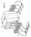
- Figure 2 depicts a front perspective view of an auxiliary switch and resistance wires in accordance with an embodiment of the invention;
- Figure 3 depicts a side view of a resistance wire in accordance with an embodiment of the invention;
- Figure 4 depicts an enlarged front perspective view of a second terminal connector in accordance with an embodiment of the invention;
- Figures 5, 6 and 7 depict cross sections of various contact surface geometries in accordance with embodiments of the invention;
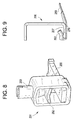
- Figure 8 depicts a side perspective view of a main terminal connector in accordance with embodiments of the invention; and
- Figure 9 depicts a side view of a main terminal connector in accordance with embodiments of the invention.
- An embodiment of the invention provides a resistance wire having a single piece snap fit terminal, which is easy to manufacture and assemble. There are no housings and no additional connecting terminals used in conjunction with the resistance wire. The resistor terminal is directly snapped into the main terminal of the contactor. As compared with the resistance wire disposed within a housing, use of the snap fit terminal allows for a part count reduction and the avoidance of additional plastic housing parts. Use of a separate plastic module including complicated molds and extended terminals, an intermediate plastic housing, terminals, and connecting screws for housing the resistor wire and for terminating the resistor wire onto the main terminal of the contactor, may all be avoided.
- Referring now to Figure 1, an exemplary embodiment of a switching
apparatus 100 is depicted. Theswitching apparatus 100 includes anelectrical contactor 110 and anauxiliary switch 120. The electrical contactor includes a set ofmain terminals 200 per each phase. Themain terminals 200 are each configured to receive aphase conductor 205. Theauxiliary switch 120 includes a set ofauxiliary terminals 210 per phase. It will be appreciated that although the perspective in Figure 1 depicts only threemain terminals 200,auxiliary terminals 210, andphase conductors 205 on one end, the switching apparatus depicted in Figure 1 has a complementary set of the above components disposed out of view at the other opposite end. - In an embodiment, each set of the
auxiliary terminals 210 is electrically connected to the respective set of themain terminals 200 via aresistance wire 250, such that each set of theauxiliary terminals 210 is electrically connected in parallel with each respective set of themain terminals 200. In an embodiment, eachresistance wire 250 is electrically insulated. In an embodiment, the electrical insulation comprises aninsulation sleeve 249 that is applied to the exterior of eachresistance wire 250. - In an embodiment, the
resistance wires 250 each comprise a plurality ofloops 251. The total length of theresistance wire 250 is determined by a desired resistance value. Theloops 251 are configured to reduce the overall length between theauxiliary terminals 210 and themain terminals 200 required for the specific length ofresistance wire 250 having the desired resistance value. - In an embodiment, the
loops 251 are each configured and disposed above the openings of themain terminals 200 to provide unobstructed access by the end user to themain terminals 200. Disposition of theloops 251, absent a housing, above themain terminal 200 openings allow for simplified installation of thephase conductors 205, and also provide for an enhancement of the dissipation of any heat that may be generated by thephase conductors 205. Theloops 251 are disposed such that eachresistance wire 250 is exposed to the same ambient environment as theauxiliary switch 120, thereby enhancing the dissipation of any heat that may be generated by theresistance wire 250 in operation. In an alternate embodiment, theloops 251 are disposed such that each electrically insulatedresistance wire 250 is exposed to the same ambient environment as theauxiliary switch 120. - While an embodiment of the invention has been depicted having a three phase switching apparatus, it will be appreciated that the scope of the invention is not so limited, and that invention also applies to other switching apparatuses having different numbers of phases, such as one, two, four, or more distinct phase paths, for example.
- Referring now to Figure 2, an exemplary embodiment of the
auxiliary switch 120 in connection with theresistance wires 250 is depicted. - Referring now to Figure 3 with reference back to Figure 1, a side view of an exemplary embodiment of the
resistance wire 250 is depicted. Eachresistance wire 250 includes afirst terminal 260 at afirst end 265, which is configured to connect to one of the set ofauxiliary terminals 210. Theresistance wire 250 also includes asecond terminal 270 at asecond end 275 configured to connect to a respective one of the set ofmain terminals 200. Thesecond terminal 270 of theresistance wire 250 comprises aretention hook 300 configured to hook onto the respectivemain terminal 200. As used herein,reference numeral 300 will refer to retention hooks generally. Theretention hook 300 comprises aconnection tab 309 to provide electrical connection to theresistance wire 250. Thesecond terminal 270 comprises acontact surface 271 disposed and configured to make contact with thephase conductor 205. - Figure 4 depicts an enlarged perspective view of the
second terminal 270. It may be appreciated from the perspective of Figure 4 that in an exemplary embodiment, thesecond terminal 270 may have one of a concave and aflat contact surface 271. - Referring now to Figures 5, 6 and 7, cross sectional views of the
cylindrical phase conductor 205 are depicted in relation to contact surfaces 271. It may be appreciated that a flat 272contact surface 271 and a concave 273contact surface 271, as provided by embodiments of thesecond terminal 270 will provide a greater area of contact than the convex 274contact surface 271 that would be provided by thecylindrical resistance wire 250 in the absence of thesecond terminal 270. Accordingly, it may be appreciated that the flat 272contact surface 271 and concave 273contact surface 271 shall provide enhanced mechanical contact with thephase conductor 205. - While an embodiment of the invention has been depicted having a
second terminal 270 with two retention hooks 300, it may be appreciated that the scope of the invention is not so limited, and that the invention also applies to othersecond terminals 270 having different numbers of retention hooks 300, such as one, three, four, or more retention hooks, for example. - Referring now to Figure 8, an exemplary embodiment of a
connector 201 in conjunction with one of themain terminals 200 is depicted. In an embodiment, eachmain terminal 200 comprises aconnector 201 having awire clamp 202 and aclamp screw 203. The phase conductor 205 (shown in Figure 1) is inserted between themain terminal 200 and thewire clamp 202. As theclamp screw 203 is tightened, it provides compressive pressure to thewire clamp 202 to retain thephase conductor 205 between thewire clamp 202 and themain terminal 200. Theclamp screw 203 is configured to withstand an application of at least 6.16 Nm of torque without damage thereto. - Referring now to Figure 8 in conjunction with Figure 4, it may be appreciated that the
second terminal 270 is configured to be disposed adjacent thewire clamp 202, above the phase conductor 205 (not shown in Figure 8). In an embodiment, the retention hooks 305, 306 are configured to slidably engage thewire clamp 202. In an embodiment, to increase the strength of the mechanical connection between the retention hooks 305, 306 and thewire clamp 202, the retention hooks 305, 306 are configured to slidably engage with thewire clamp 202 with a compressive load. Thehooks dimension 301 that is less than the thickness of thewire clamp 202 to provide the compressive load. In an alternate embodiment, the retention hooks 305, 306 are configured to snap fit onto thewire clamp 202 to enhance the strength of the mechanical connection between thewire clamp 202 and thesecond terminal 270. The snap fit of the retention hooks 300 is provided by snap features 303, 304 disposed upon the retention hooks 305, 306. The snap features 303, 304 are configured to be protrusions extending from the retention hooks 305, 306 into the surface of thewire clamp 202. - While an embodiment of the invention has been depicted to provide a snap fit by having protrusions extending from the retention hooks 305, 306, it will be appreciated that the scope of the invention is not so limited, and that the invention also applies to alternate configurations to provide a snap fit, such as ribs, knurls, or protrusions extending from the wire clamp into recesses in the bottom of the retention hooks, for example.
- Referring now to Figure 9, an alternate embodiment of the
connector 206 of themain terminal 200 is depicted. Theconnector 206 comprises aconnection tab 207. Theretention hook 302 of thesecond terminal 270 is configured to snap fit onto theconnection tab 207 with a compressive load. - The embodiments of the
second terminal 270 described above are configured to ensure that thesecond terminal 270 and theterminal connector phase conductor 205 to themain terminal 200. Eachsecond terminal 270 is configured to withstand at least 10 kilograms of pullout force for at least one minute without becoming disengaged from themain terminal 200. Pullout force indicates a force that is applied directly to theresistance wire 250 to disengage it from themain terminal 200, as may be illustrated by the direction line F in Figure 1. Further, theresistance wire 250 andsecond terminal 270 are configured to maintain a temperature below 65 degrees Celsius in response to the application of the amount of current for which thecontactor 110 is rated. - As disclosed, some embodiments of the invention may include some of the following advantages: improved integrity of the resistor termination to ensure that the resistance wire remains connected with the main terminal; increased available space for the phase conductor to be terminated; improved resistance wire and phase conductor heat dissipation; reduced total cost resulting from fewer parts; and, increased ease of assembly using top-down assembly methods.
- While the invention has been described with reference to exemplary embodiments, it will be understood by those skilled in the art that various changes may be made and equivalents may be substituted for elements thereof without departing from the scope of the invention. In addition, many modifications may be made to adapt a particular situation or material to the teachings of the invention without departing from the essential scope thereof. Therefore, it is intended that the invention not be limited to the particular embodiment disclosed as the best or only mode contemplated for carrying out this invention, but that the invention will include all embodiments falling within the scope of the appended claims. Also, in the drawings and the description, there have been disclosed exemplary embodiments of the invention and, although specific terms may have been employed, they are unless otherwise stated used in a generic and descriptive sense only and not for purposes of limitation, the scope of the invention therefore not being so limited. Moreover, the use of the terms first, second, etc. do not denote any order or importance, but rather the terms first, second, etc. are used to distinguish one element from another. Furthermore, the use of the terms a, an, etc. do not denote a limitation of quantity, but rather denote the presence of at least one of the referenced item.
Claims (10)
- A switching apparatus (100), comprising:an electrical contactor (110) including a set of main terminals (200) per phase; andan auxiliary switch (120) including a set of auxiliary terminals (210) per phase, each set of the auxiliary terminals (210) being electrically connected to a respective set of the main terminals (200) via a resistance wire (250), such that each set of the auxiliary terminals (210) is electrically connected in parallel with each respective set of the main terminals (200);wherein each resistance wire (250) includes a first terminal (260) at a first end (265) configured to connect to one of the set of auxiliary terminals (210), and a second terminal (270) at a second end (275) configured to connect to a respective one of the set of main terminals (200);
wherein the second terminal (270) of the resistance wire (250) comprises a retention hook (300) configured to hook onto the respective main terminal (200). - The apparatus (100) of Claim 1, wherein the main terminals (200) are each configured to receive a phase conductor (205), and further wherein:the second terminal (270) comprises a contact surface (271) disposed and configured to make contact with the phase conductor (205).
- The apparatus (100) of Claim 2, wherein:the contact surface (271) comprises at least one of a flat contact surface (272) and a concave contact surface (273).
- The apparatus (100) of Claim 1, wherein:the resistance wires (250) each comprise a plurality of loops (251), the loops (251) configured to reduce the overall length required for a specific length of wire (250); andthe loops (251) are each configured and disposed to provide unobstructed access to the main terminals (200).
- The apparatus (100) of Claim 1, wherein:each resistance wire (250) is electrically insulated.
- The apparatus (100) of Claim 1, wherein:each resistance wire (250) is exposed to the same ambient as the auxiliary switch (120).
- The apparatus (100) of Claim 1, wherein:each main terminal (200) comprises a connector (201) having a wire clamp (202);the retention hook (300) is configured to slidably engage the wire clamp (202); andthe retention hook (300) is configured to slidably engage with the wire clamp (202) with a compressive load.
- The apparatus (100) of Claim 1, wherein:each main terminal (200) comprises a connector (201) having a wire clamp (202); andthe retention hook (300) is configured to snap fit onto the wire clamp (202).
- The apparatus (100) of Claim 1, wherein:each main terminal (200) comprises a connection tab (207); andthe retention hook (302) is configured to snap fit onto the connection tab (207) with a compressive load.
- The apparatus (100) of Claim 1, wherein:each main terminal (200) comprises a connector (201) having a wire clamp (202) and a clamp screw (203).
Applications Claiming Priority (1)
| Application Number | Priority Date | Filing Date | Title |
|---|---|---|---|
| US11/462,896 US7540792B2 (en) | 2006-08-07 | 2006-08-07 | Switching apparatus |
Publications (2)
| Publication Number | Publication Date |
|---|---|
| EP1887600A1 true EP1887600A1 (en) | 2008-02-13 |
| EP1887600B1 EP1887600B1 (en) | 2017-11-08 |
Family
ID=38616286
Family Applications (1)
| Application Number | Title | Priority Date | Filing Date |
|---|---|---|---|
| EP07113400.1A Active EP1887600B1 (en) | 2006-08-07 | 2007-07-30 | Switching apparatus |
Country Status (3)
| Country | Link |
|---|---|
| US (1) | US7540792B2 (en) |
| EP (1) | EP1887600B1 (en) |
| CN (1) | CN101123152B (en) |
Cited By (2)
| Publication number | Priority date | Publication date | Assignee | Title |
|---|---|---|---|---|
| KR200450346Y1 (en) | 2008-12-03 | 2010-09-28 | 엘에스산전 주식회사 | Wire contactor of magnetic contactor |
| WO2017137373A1 (en) * | 2016-02-10 | 2017-08-17 | Te Connectivity Germany Gmbh | Current transmission device having a monitoring device |
Families Citing this family (9)
| Publication number | Priority date | Publication date | Assignee | Title |
|---|---|---|---|---|
| US7798869B1 (en) * | 2008-06-10 | 2010-09-21 | Woodard Govenor Company | Electrical connector |
| KR200456638Y1 (en) * | 2010-05-20 | 2011-11-09 | 엘에스산전 주식회사 | Supporting mechanism of coil terminal for magnetic contactor |
| EP2874167B1 (en) * | 2012-07-13 | 2017-06-28 | Siemens Aktiengesellschaft | Junction box and contactor device |
| FR2997237B1 (en) * | 2012-10-23 | 2014-11-21 | Schneider Electric Ind Sas | ELASTIC CAGE FOR CONNECTING TERMINAL AND TERMINAL COMPRISING SUCH A CAGE |
| DE102013226438A1 (en) * | 2013-12-18 | 2015-06-18 | Siemens Aktiengesellschaft | Contactor with external resistor |
| US9590520B2 (en) | 2014-11-24 | 2017-03-07 | Hamilton Sundstrand Corporation | Inductive clamping circuit |
| US9299523B1 (en) * | 2014-12-12 | 2016-03-29 | Eaton Corporation | Switching device assembly and adapter assembly therefor |
| CN106653492A (en) * | 2015-10-29 | 2017-05-10 | 茆敦华 | Alternating (direct) current non-arc contactor possessing series-resistance-type circuit division and combination system |
| CN110517933B (en) * | 2019-08-07 | 2024-08-06 | 德力西电气有限公司 | Resistor wire connection device of switching capacitor contactor |
Citations (5)
| Publication number | Priority date | Publication date | Assignee | Title |
|---|---|---|---|---|
| US2706804A (en) * | 1952-09-27 | 1955-04-19 | Gilbert Co A C | Wire connection binding clip |
| US4437020A (en) | 1981-02-12 | 1984-03-13 | Siemens Aktiengesellschaft | Electromagnetic switchgear |
| JPH08130042A (en) * | 1994-10-31 | 1996-05-21 | Kobe Steel Ltd | High current power supply connector |
| JPH09161861A (en) | 1995-12-01 | 1997-06-20 | Sumitomo Wiring Syst Ltd | Mounting structure of earth terminal |
| US5689143A (en) * | 1995-06-09 | 1997-11-18 | Allen-Bradley Company, Inc. | Arrangement of resistors for switching of capacitive loads in an electromagnetic switching device |
Family Cites Families (40)
| Publication number | Priority date | Publication date | Assignee | Title |
|---|---|---|---|---|
| US1611567A (en) * | 1918-05-17 | 1926-12-21 | Square D Co | Rotatable bar and bearing and method of mounting same |
| US1580562A (en) * | 1923-04-11 | 1926-04-13 | Lynette D Baker | Translucent sparn-plug intensipier |
| US1767808A (en) * | 1928-06-08 | 1930-06-24 | Charles T Nietman | Terminal connecter for electric conductors |
| US2254754A (en) * | 1939-08-24 | 1941-09-02 | Harvey M Reece | Contact plug for electric cords |
| US2570753A (en) * | 1949-02-08 | 1951-10-09 | Aircraft Marine Prod Inc | Spade connector convertible to ring connector |
| US3423723A (en) * | 1967-02-13 | 1969-01-21 | Murray Mfg Corp | Jaw construction for bladejaw contacts |
| US3340497A (en) * | 1967-02-23 | 1967-09-05 | George K Garrett Company | Electric wire-terminal spring clips |
| US3585576A (en) * | 1969-08-08 | 1971-06-15 | Western Electric Co | Self-locking insertion-type connector |
| US3733574A (en) * | 1971-07-23 | 1973-05-15 | Vector Electronic Co | Miniature tandem spring clips |
| BE794320A (en) * | 1972-01-19 | 1973-07-19 | Thomas & Betts Corp | INSULATION AND OXIDE DRILLING CONTACT MEANS |
| US3861780A (en) * | 1973-04-18 | 1975-01-21 | Ii James C Hobbs | Self-closing terminal connector |
| US3891298A (en) * | 1973-09-17 | 1975-06-24 | Westinghouse Electric Corp | Clip connected terminal lug |
| US3864005A (en) * | 1973-10-11 | 1975-02-04 | Gen Electric | Resilient electrical terminal connector |
| US3918790A (en) * | 1974-06-14 | 1975-11-11 | Minnesota Mining & Mfg | Snap spade electrical connector |
| JPH0244469Y2 (en) * | 1984-12-28 | 1990-11-26 | ||
| US4699445A (en) * | 1986-07-28 | 1987-10-13 | Amp Incorporated | Electrical terminal assembly for thermistors |
| US4775337A (en) * | 1986-12-02 | 1988-10-04 | Universal Manufacturing Corporation | Conductive wire with integral electrical terminal |
| US4739293A (en) * | 1987-02-19 | 1988-04-19 | Westinghouse Electric Corp. | Electromagnetic contactor with reduced noise magnetic armature |
| JPH076595Y2 (en) * | 1988-08-10 | 1995-02-15 | 富士電機株式会社 | Electromagnetic contactor |
| US4944692A (en) * | 1989-02-24 | 1990-07-31 | Allina Edward F | Electrical plug-in connectors |
| DE9003209U1 (en) * | 1990-03-19 | 1991-07-18 | Siemens Nixdorf Informationssysteme AG, 4790 Paderborn | Contact strip for an interference-proof connection of adjacent metallic wall elements |
| US5206789A (en) * | 1992-03-05 | 1993-04-27 | Westinghouse Electric Corp. | Terminal assembly for a circuit breaker and similar apparatus |
| JPH07245136A (en) * | 1994-03-02 | 1995-09-19 | Keiko Kaedei | Metal piece for electric connection |
| US5483213A (en) * | 1994-05-27 | 1996-01-09 | Eaton Corporation | Terminal block with terminal-locking slot |
| US5493085A (en) * | 1995-02-17 | 1996-02-20 | Eaton Corporation | Spring clip assembly for electrical connections to flat stabs and switches incorporating the same |
| US5872498A (en) * | 1997-05-20 | 1999-02-16 | Allen-Bradley Company, Llc | Resistance arrangement for an electromagnetic switching device useable for switching capacitive loads |
| DE19729595C1 (en) * | 1997-07-10 | 1998-10-22 | Siemens Ag | Capacitor switching contactor arrangement |
| US6034584A (en) * | 1997-08-06 | 2000-03-07 | Allen-Bradley Company, Llc | Arrangement for mechanically coupling an overload relay to a contactor |
| TW443627U (en) * | 1998-11-16 | 2001-06-23 | Acer Peripherals Inc | Input/output connector |
| US6283770B1 (en) * | 1998-12-11 | 2001-09-04 | Cisco Technology, Incc. | Minimal intrusion EMI shielding clip to maintain electrical contact between two parallel surfaces |
| US6102750A (en) * | 1998-12-29 | 2000-08-15 | Eaton Corporation | Self-retaining spring clip assembly and an electrical connection incorporating the same |
| FR2792118B1 (en) * | 1999-04-12 | 2001-06-01 | Entrelec Sa | METHOD AND DEVICE FOR INTERCONNECTING TERMINALS |
| JP3077696B1 (en) * | 1999-08-17 | 2000-08-14 | 住友電装株式会社 | connector |
| JP4443691B2 (en) * | 1999-10-18 | 2010-03-31 | 第一電子工業株式会社 | Terminal block |
| JP4258972B2 (en) * | 2000-12-22 | 2009-04-30 | 富士電機機器制御株式会社 | Box terminal for appliances |
| DE10137497C5 (en) * | 2001-07-31 | 2005-09-15 | Siemens Ag | switchgear |
| US6716052B2 (en) * | 2002-02-21 | 2004-04-06 | Tyco Electronics Corporation | Connector position assurance device and latch |
| DE10236790C1 (en) * | 2002-08-10 | 2003-10-16 | Moeller Gmbh | Electrical switching device has incoming and/or outgoing contacts provided with external electrical lead terminals and second terminals for second electrical conductor |
| CN2667692Y (en) * | 2003-09-11 | 2004-12-29 | 富士康(昆山)电脑接插件有限公司 | Electric connector |
| US6942527B1 (en) * | 2004-02-19 | 2005-09-13 | Eaton Corporation | Dual function terminal assembly and electric power apparatus incorporating the same |
-
2006
- 2006-08-07 US US11/462,896 patent/US7540792B2/en active Active
-
2007
- 2007-07-30 EP EP07113400.1A patent/EP1887600B1/en active Active
- 2007-08-07 CN CN2007101399907A patent/CN101123152B/en active Active
Patent Citations (5)
| Publication number | Priority date | Publication date | Assignee | Title |
|---|---|---|---|---|
| US2706804A (en) * | 1952-09-27 | 1955-04-19 | Gilbert Co A C | Wire connection binding clip |
| US4437020A (en) | 1981-02-12 | 1984-03-13 | Siemens Aktiengesellschaft | Electromagnetic switchgear |
| JPH08130042A (en) * | 1994-10-31 | 1996-05-21 | Kobe Steel Ltd | High current power supply connector |
| US5689143A (en) * | 1995-06-09 | 1997-11-18 | Allen-Bradley Company, Inc. | Arrangement of resistors for switching of capacitive loads in an electromagnetic switching device |
| JPH09161861A (en) | 1995-12-01 | 1997-06-20 | Sumitomo Wiring Syst Ltd | Mounting structure of earth terminal |
Cited By (2)
| Publication number | Priority date | Publication date | Assignee | Title |
|---|---|---|---|---|
| KR200450346Y1 (en) | 2008-12-03 | 2010-09-28 | 엘에스산전 주식회사 | Wire contactor of magnetic contactor |
| WO2017137373A1 (en) * | 2016-02-10 | 2017-08-17 | Te Connectivity Germany Gmbh | Current transmission device having a monitoring device |
Also Published As
| Publication number | Publication date |
|---|---|
| CN101123152A (en) | 2008-02-13 |
| US20080055025A1 (en) | 2008-03-06 |
| CN101123152B (en) | 2012-07-11 |
| US7540792B2 (en) | 2009-06-02 |
| EP1887600B1 (en) | 2017-11-08 |
Similar Documents
| Publication | Publication Date | Title |
|---|---|---|
| EP1887600A1 (en) | Switching apparatus | |
| EP2416451B1 (en) | Electrical connector | |
| KR101873065B1 (en) | Electric fuse with torque restricting terminals | |
| US5378552A (en) | Modular battery system comprising individual interconnected modules | |
| US6814600B2 (en) | Hermaphroditic contact part | |
| EP2534737B1 (en) | Connector assembly for an interlock circuit | |
| US6285271B1 (en) | Capacitor switching contactor | |
| EP1936743B1 (en) | Double connection terminal screw/plug-in for electrical apparatus | |
| US7666033B1 (en) | Power plug with over temperature and over current protection | |
| US20140073189A1 (en) | Power cord | |
| US20040137771A1 (en) | Remakeable connector arrangement | |
| EP2472551A1 (en) | Circuit breaker | |
| US10283293B2 (en) | Thermal circuit breaker | |
| EP1335471A2 (en) | Solid state relay | |
| WO2014143494A1 (en) | Heat reducing terminals including a surface having protrusions and electrical switching apparatus including the same | |
| CN102064059B (en) | Leakage breaker | |
| US10020613B2 (en) | Power terminal for arcless power connector | |
| US12603457B2 (en) | Plug-in contact device for preventing an arc when separating a direct current connection | |
| US6388554B1 (en) | Circuit breaker device | |
| CN201364863Y (en) | Thermal overload protection device and bimetal trigger device assembly | |
| US20120156931A1 (en) | Electrical connector having a resistor | |
| CN102194621B (en) | Fuse cell | |
| CN215896634U (en) | Secondary battery and battery module including the same | |
| JP2009021053A (en) | Plug-in type terminal connection failure detection device | |
| CN102376467B (en) | Contact element and the system including contact element and counter element |
Legal Events
| Date | Code | Title | Description |
|---|---|---|---|
| PUAI | Public reference made under article 153(3) epc to a published international application that has entered the european phase |
Free format text: ORIGINAL CODE: 0009012 |
|
| AK | Designated contracting states |
Kind code of ref document: A1 Designated state(s): AT BE BG CH CY CZ DE DK EE ES FI FR GB GR HU IE IS IT LI LT LU LV MC MT NL PL PT RO SE SI SK TR |
|
| AX | Request for extension of the european patent |
Extension state: AL BA HR MK YU |
|
| 17P | Request for examination filed |
Effective date: 20080813 |
|
| 17Q | First examination report despatched |
Effective date: 20080922 |
|
| AKX | Designation fees paid |
Designated state(s): DE ES FR GB IT |
|
| GRAP | Despatch of communication of intention to grant a patent |
Free format text: ORIGINAL CODE: EPIDOSNIGR1 |
|
| RIC1 | Information provided on ipc code assigned before grant |
Ipc: H01R 4/36 20060101ALN20170510BHEP Ipc: H01H 50/54 20060101AFI20170510BHEP |
|
| INTG | Intention to grant announced |
Effective date: 20170602 |
|
| GRAS | Grant fee paid |
Free format text: ORIGINAL CODE: EPIDOSNIGR3 |
|
| GRAA | (expected) grant |
Free format text: ORIGINAL CODE: 0009210 |
|
| AK | Designated contracting states |
Kind code of ref document: B1 Designated state(s): DE ES FR GB IT |
|
| REG | Reference to a national code |
Ref country code: GB Ref legal event code: FG4D |
|
| REG | Reference to a national code |
Ref country code: DE Ref legal event code: R096 Ref document number: 602007052944 Country of ref document: DE |
|
| PG25 | Lapsed in a contracting state [announced via postgrant information from national office to epo] |
Ref country code: ES Free format text: LAPSE BECAUSE OF FAILURE TO SUBMIT A TRANSLATION OF THE DESCRIPTION OR TO PAY THE FEE WITHIN THE PRESCRIBED TIME-LIMIT Effective date: 20171108 |
|
| REG | Reference to a national code |
Ref country code: DE Ref legal event code: R097 Ref document number: 602007052944 Country of ref document: DE |
|
| PG25 | Lapsed in a contracting state [announced via postgrant information from national office to epo] |
Ref country code: IT Free format text: LAPSE BECAUSE OF FAILURE TO SUBMIT A TRANSLATION OF THE DESCRIPTION OR TO PAY THE FEE WITHIN THE PRESCRIBED TIME-LIMIT Effective date: 20171108 |
|
| PLBE | No opposition filed within time limit |
Free format text: ORIGINAL CODE: 0009261 |
|
| STAA | Information on the status of an ep patent application or granted ep patent |
Free format text: STATUS: NO OPPOSITION FILED WITHIN TIME LIMIT |
|
| 26N | No opposition filed |
Effective date: 20180809 |
|
| GBPC | Gb: european patent ceased through non-payment of renewal fee |
Effective date: 20180730 |
|
| PG25 | Lapsed in a contracting state [announced via postgrant information from national office to epo] |
Ref country code: FR Free format text: LAPSE BECAUSE OF NON-PAYMENT OF DUE FEES Effective date: 20180731 Ref country code: GB Free format text: LAPSE BECAUSE OF NON-PAYMENT OF DUE FEES Effective date: 20180730 |
|
| REG | Reference to a national code |
Ref country code: DE Ref legal event code: R081 Ref document number: 602007052944 Country of ref document: DE Owner name: ABB SCHWEIZ AG, CH Free format text: FORMER OWNER: GENERAL ELECTRIC COMPANY, SCHENECTADY, N.Y., US Ref country code: DE Ref legal event code: R081 Ref document number: 602007052944 Country of ref document: DE Owner name: ABB SCHWEIZ AG, CH Free format text: FORMER OWNER: GENERAL ELECTRIC COMPANY, SCHENECTADY, NY, US |
|
| REG | Reference to a national code |
Ref country code: DE Ref legal event code: R082 Ref document number: 602007052944 Country of ref document: DE Representative=s name: ZIMMERMANN & PARTNER PATENTANWAELTE MBB, DE |
|
| PGFP | Annual fee paid to national office [announced via postgrant information from national office to epo] |
Ref country code: DE Payment date: 20250722 Year of fee payment: 19 |