EP1887173A2 - Closure terminal for cremone bolt of a door or window - Google Patents
Closure terminal for cremone bolt of a door or window Download PDFInfo
- Publication number
- EP1887173A2 EP1887173A2 EP07112739A EP07112739A EP1887173A2 EP 1887173 A2 EP1887173 A2 EP 1887173A2 EP 07112739 A EP07112739 A EP 07112739A EP 07112739 A EP07112739 A EP 07112739A EP 1887173 A2 EP1887173 A2 EP 1887173A2
- Authority
- EP
- European Patent Office
- Prior art keywords
- pawl
- bush
- shoulder
- closure
- closure terminal
- Prior art date
- Legal status (The legal status is an assumption and is not a legal conclusion. Google has not performed a legal analysis and makes no representation as to the accuracy of the status listed.)
- Granted
Links
- 230000008878 coupling Effects 0.000 claims abstract description 12
- 238000010168 coupling process Methods 0.000 claims abstract description 12
- 238000005859 coupling reaction Methods 0.000 claims abstract description 12
- 230000000295 complement effect Effects 0.000 claims description 2
- 238000003780 insertion Methods 0.000 claims description 2
- 230000037431 insertion Effects 0.000 claims description 2
- 238000009434 installation Methods 0.000 description 2
- 230000000670 limiting effect Effects 0.000 description 2
- 238000004519 manufacturing process Methods 0.000 description 2
- 238000005516 engineering process Methods 0.000 description 1
- 230000013011 mating Effects 0.000 description 1
- 238000000034 method Methods 0.000 description 1
- 238000012986 modification Methods 0.000 description 1
- 230000004048 modification Effects 0.000 description 1
- 238000004080 punching Methods 0.000 description 1
Images

Classifications
-
- E—FIXED CONSTRUCTIONS
- E05—LOCKS; KEYS; WINDOW OR DOOR FITTINGS; SAFES
- E05C—BOLTS OR FASTENING DEVICES FOR WINGS, SPECIALLY FOR DOORS OR WINDOWS
- E05C9/00—Arrangements of simultaneously actuated bolts or other securing devices at well-separated positions on the same wing
- E05C9/18—Details of fastening means or of fixed retaining means for the ends of bars
- E05C9/1825—Fastening means
- E05C9/1833—Fastening means performing sliding movements
- E05C9/185—Fastening means performing sliding movements parallel with actuating bar
- E05C9/1858—Fastening means performing sliding movements parallel with actuating bar of the roller bolt type
-
- E—FIXED CONSTRUCTIONS
- E05—LOCKS; KEYS; WINDOW OR DOOR FITTINGS; SAFES
- E05C—BOLTS OR FASTENING DEVICES FOR WINGS, SPECIALLY FOR DOORS OR WINDOWS
- E05C9/00—Arrangements of simultaneously actuated bolts or other securing devices at well-separated positions on the same wing
- E05C9/24—Means for transmitting movements between vertical and horizontal sliding bars, rods or cables for the fastening of wings, e.g. corner guides
-
- E—FIXED CONSTRUCTIONS
- E05—LOCKS; KEYS; WINDOW OR DOOR FITTINGS; SAFES
- E05B—LOCKS; ACCESSORIES THEREFOR; HANDCUFFS
- E05B63/00—Locks or fastenings with special structural characteristics
- E05B63/0056—Locks with adjustable or exchangeable lock parts
Definitions
- the present invention relates to a closure terminal for a cremone bolt of a door or window.
- a cremone bolt comprises a flat fixed rod, which is fixed to the side of the leaf; the fixed rod acts as a guide for a movable rod which is arranged between the frame of the leaf and the fixed rod.
- One (or more) closure pawls protrude from the movable rod toward the outside of the leaf through a corresponding slot formed in the fixed rod; such pawl, depending on the position of the movable rod on the fixed rod, is made to perform a translational motion so as to enter and exit from a corresponding locking seat which is formed on the closure abutment jamb of the frame of the door or window or is free to exit from the locking seat.
- the distance (clearance) between the leaf and the abutment jamb can vary from one installation to another; it is therefore necessary to be able to adjust the distance of the pawl from the movable rod in order to allow the pawl to enter adequately the locking seat formed in the abutment jamb.
- a closure terminal which is constituted by a pawl which has a threaded through hole for mating with an externally threaded pin which protrudes from the movable rod of the cremone bolt.
- the position of the pawl can be adjusted on the axis of the pin in the direction of the locking seat.
- the pawl is eccentric with respect to the axis of the threaded coupling between the pin and the pawl.
- the aim of the present invention is to provide a closure terminal for a cremone bolt of a door or window which allows an axial and "lateral" adjustment of the pawl with respect to the locking seat and at the same time is constructively simple.
- an object of the present invention is to provide a closure terminal for a cremone bolt of a door or window which can be installed easily.
- Another object of the present invention is to provide a closure terminal for a cremone bolt of a door or window which is tough.
- Another object of the present invention is to provide a closure terminal for a cremone bolt of a door or window which can be manufactured with known systems and technologies.
- a closure terminal for a cremone bolt of a door or window which comprises a pawl which is adapted to be arranged in the locking seat formed on the closure abutment jamb of the door or window, said pawl being rigidly coupled by means of a threaded coupling to an intermediate body which is associated with the movable rod of the cremone bolt to be arranged on the leaf of the door or window, said threaded coupling being adapted to allow the adjustment of the position of the pawl on the axis of the thread, said pawl being eccentric with respect to said axis, characterized in that said intermediate body consists of a bush which is fixed to the movable rod of the cremone bolt and is at least partially threaded internally and in which a threaded stem which protrudes monolithically from said pawl is inserted and coupled.
- a closure terminal according to the invention is generally designated by the reference numeral 10.
- the closure terminal 10 is applied to a cremone bolt 11, of which the figures show a fixed rod 12, which is locked on a frame T of the leaf and a movable rod 13, which is arranged so as to be guided on the fixed rod 12, according to a layout which is per se of a known type.
- the fixed rod 12 closes a slot 14, which is formed on the frame of the leaf and contains the cremone bolt.
- the movable rod 13, arranged in the slot 14, is composed, according to a per se known structure, by a longitudinal plate 15, on which the closure terminal 10 is fixed, and by a flexible curved elongated body 16, which is fixed to the plate 15 by means of a rivet 17; the flexible elongated body 16 is arranged between the plate 15 and the fixed rod 12.
- the closure terminal 10 protrudes from the slot 14 toward an abutment frame B of the door or window by means of a through slot 18 provided in the fixed rod 12; the through slot 18 also acts as a longitudinal guide for the terminal 10.
- the closure terminal 10 comprises a pawl 19 which, when closed, is inserted in a locking seat S formed in the abutment frame B of the door or window.
- the pawl 19 is rigidly coupled by means of a threaded coupling to an intermediate body 20 which is associated with the movable rod 13 of the cremone bolt.
- the intermediate body 20 consists of a bush 21, which is fixed to the movable rod 13 and is partially threaded internally; the axis of the bush and of the thread coincide and protrude toward the abutment frame B of the door or window.
- a threaded stem 22 is inserted and coupled in the bush 21 and protrudes monolithically from the pawl 19.
- the pawl 19 is eccentric with respect to the axis of the threaded stem 22.
- the bush 21 is arranged so as to pass through the plate 15 and the elongated body 16.
- the bush 21 is inserted with a rotation-preventing coupling in a complementary through hole 23 formed in the plate 15 of the movable rod 13.
- both the bush portion 21 surrounded by the wall of the through hole 23 and the bush portion surrounded by the walls of the slot 18 have a rectangular contour.
- the end faces of the bush 21 protrude in a radial direction, thus forming two extraction-preventing shoulders, respectively a first extraction-preventing shoulder 24, which abuts against the edges 25 of the slot 18 directed toward the pawl 19, and a second shoulder 26, which abuts against the face 27 of the plate 15 which lies opposite the fixed rod 12.
- the extraction-preventing shoulders prevent the axial movement of the bush 21; the first shoulder 24 further helps to guide the bush 21 on the fixed rod 12.
- the second shoulder 26 is formed by plastic deformation during assembly of the closure terminal: the bush 21 is inserted in the slot 18 and in the through hole 23 from the side related to the fixed rod 12; when the first shoulder 24 abuts against the edges 25 of the slot 18 and the third shoulder 28 abuts against the plate 15, the base of the bush 21 protrudes from the hole 23 and is expanded by deformation in a known manner, thus creating the second shoulder 26.
- the distance of the pawl 19 from the fixed rod 12 depends on how far the stem 22 is inserted in the bush 23.
- the thread of the stem 22 is enlarged with respect to the internal thread of the bush 21, thus allowing a "friction” coupling which allows to adjust adequately, without the risk of unwanted movements, the axial position of the pawl 19 with respect to the bush 23.
- the stem 22 is deformed plastically at the end in order to lock it in the bush 23.
- deformation occurs by punching with a punch the end face 29 of the stem 22, which thus tends to expand, pushing against the walls of the bush 23.
- Figure 3 illustrates a structure of a bolt closure terminal in which, between the first shoulder 24 and the second shoulder 26, there is respectively the fixed rod 12, the movable rod 13 composed only of the plate 15, and a shim ring 30, which is useful to prevent axial movements of the bush 23.
- the present invention provides a closure terminal for a cremone bolt of a door or window which allows axial and "lateral" adjustment of the closure pawl which are extremely easy to perform.
- closure terminal allows its simplified manufacture and its very quick, safe and strong assembly fitting to the bolt; in this regard, attention is called to the ease with which it is possible to deform the end of the stem of the pawl in order to lock it in the bush.
- the materials employed may be any according to the requirements and the state of the art.
Landscapes
- Engineering & Computer Science (AREA)
- Mechanical Engineering (AREA)
- Window Of Vehicle (AREA)
- Lock And Its Accessories (AREA)
- Connection Of Plates (AREA)
- Wing Frames And Configurations (AREA)
Abstract
Description
- The present invention relates to a closure terminal for a cremone bolt of a door or window.
- As is known, the leaf of a door or window is closed and opened by means of a handle which is connected to a closure terminal by means of a so-called cremone bolt.
- A cremone bolt comprises a flat fixed rod, which is fixed to the side of the leaf; the fixed rod acts as a guide for a movable rod which is arranged between the frame of the leaf and the fixed rod.
- One (or more) closure pawls protrude from the movable rod toward the outside of the leaf through a corresponding slot formed in the fixed rod; such pawl, depending on the position of the movable rod on the fixed rod, is made to perform a translational motion so as to enter and exit from a corresponding locking seat which is formed on the closure abutment jamb of the frame of the door or window or is free to exit from the locking seat.
- Depending on the type of door or window and on the accuracy of the assembly of a door or window, the distance (clearance) between the leaf and the abutment jamb can vary from one installation to another; it is therefore necessary to be able to adjust the distance of the pawl from the movable rod in order to allow the pawl to enter adequately the locking seat formed in the abutment jamb.
- To do this, one solution is to provide a closure terminal which is constituted by a pawl which has a threaded through hole for mating with an externally threaded pin which protrudes from the movable rod of the cremone bolt.
- In this manner, the position of the pawl can be adjusted on the axis of the pin in the direction of the locking seat.
- Such a solution is shown for example in
EP-0870890 . - In such patent, the pawl is eccentric with respect to the axis of the threaded coupling between the pin and the pawl.
- In this manner, it is possible to adjust not only the axial distance but also the "lateral" position of the pawl, arranging it so that it rests against the side of the locking seat; in this manner, the pawl is prevented from being "loose" within the locking seat (the seat, in order to ensure the insertion of the pawl, is in fact larger than said pawl).
- Although this solution is extremely valid in the concept of axial and "lateral" adjustment of the pawl, it has limitations during production and installation which are linked to the particular geometry chosen.
- The aim of the present invention is to provide a closure terminal for a cremone bolt of a door or window which allows an axial and "lateral" adjustment of the pawl with respect to the locking seat and at the same time is constructively simple.
- Within this aim, an object of the present invention is to provide a closure terminal for a cremone bolt of a door or window which can be installed easily.
- Another object of the present invention is to provide a closure terminal for a cremone bolt of a door or window which is tough.
- Another object of the present invention is to provide a closure terminal for a cremone bolt of a door or window which can be manufactured with known systems and technologies.
- This aim and these and other objects, which will become better apparent hereinafter, are achieved by a closure terminal for a cremone bolt of a door or window, which comprises a pawl which is adapted to be arranged in the locking seat formed on the closure abutment jamb of the door or window, said pawl being rigidly coupled by means of a threaded coupling to an intermediate body which is associated with the movable rod of the cremone bolt to be arranged on the leaf of the door or window, said threaded coupling being adapted to allow the adjustment of the position of the pawl on the axis of the thread, said pawl being eccentric with respect to said axis, characterized in that said intermediate body consists of a bush which is fixed to the movable rod of the cremone bolt and is at least partially threaded internally and in which a threaded stem which protrudes monolithically from said pawl is inserted and coupled.
- Further characteristics and advantages of the invention will become better apparent from the following detailed description of a preferred but not exclusive embodiment thereof, illustrated by way of non-limiting example in the accompanying drawings, wherein:
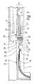
- Figure 1 is a longitudinal sectional view of a portion of a cremone bolt with a closure terminal according to the invention applied thereto;
- Figure 2 is a transverse sectional view of the cremone bolt of Figure 1, taken at the closure terminal;
- Figure 3 is a longitudinal sectional view of a closure terminal according to the invention, applied to a portion of a cremone bolt which is a variation with respect to the one of the preceding figures.
- It is noted that anything found to be already known during the patenting process is understood not to be claimed and to be the subject of a disclaimer.
- With reference to the figures, a closure terminal according to the invention is generally designated by the
reference numeral 10. - The
closure terminal 10 is applied to a cremone bolt 11, of which the figures show afixed rod 12, which is locked on a frame T of the leaf and amovable rod 13, which is arranged so as to be guided on thefixed rod 12, according to a layout which is per se of a known type. - The
fixed rod 12 closes aslot 14, which is formed on the frame of the leaf and contains the cremone bolt. - The
movable rod 13, arranged in theslot 14, is composed, according to a per se known structure, by alongitudinal plate 15, on which theclosure terminal 10 is fixed, and by a flexible curvedelongated body 16, which is fixed to theplate 15 by means of a rivet 17; the flexibleelongated body 16 is arranged between theplate 15 and thefixed rod 12. - The
closure terminal 10 protrudes from theslot 14 toward an abutment frame B of the door or window by means of a throughslot 18 provided in thefixed rod 12; the throughslot 18 also acts as a longitudinal guide for theterminal 10. - The
closure terminal 10 comprises apawl 19 which, when closed, is inserted in a locking seat S formed in the abutment frame B of the door or window. - The
pawl 19 is rigidly coupled by means of a threaded coupling to anintermediate body 20 which is associated with themovable rod 13 of the cremone bolt. - In particular, the
intermediate body 20 consists of abush 21, which is fixed to themovable rod 13 and is partially threaded internally; the axis of the bush and of the thread coincide and protrude toward the abutment frame B of the door or window. - A threaded
stem 22 is inserted and coupled in thebush 21 and protrudes monolithically from thepawl 19. - The
pawl 19 is eccentric with respect to the axis of the threadedstem 22. - The
bush 21 is arranged so as to pass through theplate 15 and theelongated body 16. - In particular, the
bush 21 is inserted with a rotation-preventing coupling in a complementary throughhole 23 formed in theplate 15 of themovable rod 13. - For example, both the
bush portion 21 surrounded by the wall of the throughhole 23 and the bush portion surrounded by the walls of theslot 18 have a rectangular contour. - The end faces of the
bush 21 protrude in a radial direction, thus forming two extraction-preventing shoulders, respectively a first extraction-preventingshoulder 24, which abuts against theedges 25 of theslot 18 directed toward thepawl 19, and asecond shoulder 26, which abuts against the face 27 of theplate 15 which lies opposite thefixed rod 12. - The extraction-preventing shoulders prevent the axial movement of the
bush 21; thefirst shoulder 24 further helps to guide thebush 21 on thefixed rod 12. - As can be seen in Figure 1, at the rim of the through
hole 23 there is athird shoulder 28, which abuts against the face of theplate 15 that lies opposite the face 27 against which thesecond shoulder 26 abuts. - From a practical standpoint, the
second shoulder 26 is formed by plastic deformation during assembly of the closure terminal: thebush 21 is inserted in theslot 18 and in the throughhole 23 from the side related to thefixed rod 12; when thefirst shoulder 24 abuts against theedges 25 of theslot 18 and thethird shoulder 28 abuts against theplate 15, the base of thebush 21 protrudes from thehole 23 and is expanded by deformation in a known manner, thus creating thesecond shoulder 26. - Once the
bush 21 has been locked, the threadedstem 22, which protrudes from thepawl 19, is inserted therein. - The distance of the
pawl 19 from the fixed rod 12 (and therefore the distance from the locking seat 20) depends on how far thestem 22 is inserted in thebush 23. - Advantageously, the thread of the
stem 22 is enlarged with respect to the internal thread of thebush 21, thus allowing a "friction" coupling which allows to adjust adequately, without the risk of unwanted movements, the axial position of thepawl 19 with respect to thebush 23. - Further, once the chosen axial position has been found (as well as the "lateral" adjustment of the pawl: a rotation of the stem is matched by a rotation of the eccentric part of the pawl), the
stem 22 is deformed plastically at the end in order to lock it in thebush 23. - For example, deformation occurs by punching with a punch the
end face 29 of thestem 22, which thus tends to expand, pushing against the walls of thebush 23. - Figure 3 illustrates a structure of a bolt closure terminal in which, between the
first shoulder 24 and thesecond shoulder 26, there is respectively thefixed rod 12, themovable rod 13 composed only of theplate 15, and ashim ring 30, which is useful to prevent axial movements of thebush 23. - In practice it has been found that the invention thus described achieves the intended aim and objects.
- In particular, the present invention provides a closure terminal for a cremone bolt of a door or window which allows axial and "lateral" adjustment of the closure pawl which are extremely easy to perform.
- The particular structure of the closure terminal allows its simplified manufacture and its very quick, safe and strong assembly fitting to the bolt; in this regard, attention is called to the ease with which it is possible to deform the end of the stem of the pawl in order to lock it in the bush.
- The invention thus conceived is susceptible of numerous modifications and variations, all of which are within the scope of the appended claims; all the details may further be replaced with other technically equivalent elements.
- In practice, the materials employed, so long as they are compatible with the specific use, as well as the dimensions, may be any according to the requirements and the state of the art.
- The disclosures in
Italian Patent Application No. PD2006A000300 - Where technical features mentioned in any claim are followed by reference signs, those reference signs have been included for the sole purpose of increasing the intelligibility of the claims and accordingly such reference signs do not have any limiting effect on the interpretation of each element identified by way of example by such reference signs.
Claims (9)
- A closure terminal for a cremone bolt of a door or window, comprising a pawl (19) which is adapted to be arranged in the locking seat (S) formed on the closure abutment jamb (B) of the door or window, said pawl (19) being rigidly coupled by means of a threaded coupling to an intermediate body (20), which is associated with the movable rod (13) of the cremone bolt (11) to be arranged on the leaf of the door or window, said threaded coupling being adapted to allow the adjustment of the position of said pawl (19) on the axis of the thread, said pawl (19) being eccentric with respect to said axis, characterized in that said intermediate body (20) consists of a bush (21) which is fixed to the movable rod (13) of the cremone bolt and is at least partially threaded internally and in which a threaded stem (22) which protrudes monolithic ally from said pawl (19) is inserted and coupled.
- The closure terminal according to claim 1, characterized in that said bush (21) is inserted with a rotation-preventing coupling in a complementary through hole (23) provided in a part of said movable rod (13).
- The closure terminal according to the preceding claims, characterized in that at least the portion of said bush (21) that is surrounded by the wall of said through hole (23) has a quadrangular contour.
- The closure terminal according to one or more of the preceding claims, characterized in that the end faces of said bush (21) protrude radially with respect to the axis of said bush (21), forming two extraction-preventing shoulders, respectively a first extraction-preventing shoulder (24), which abuts against the edges (25) of a through slot (18) formed in the fixed rod (12) of the bolt (11) which are directed toward said pawl (19), and a second shoulder (26), which abuts against the face (27) of the part of said movable rod (13) that lies opposite said fixed rod (12), said extraction-preventing shoulders (24, 26) preventing the axial movement of said bush (21).
- The closure terminal according to the preceding claims, characterized in that a third shoulder (28) is provided at the rim of said through hole (23) and abuts against the face of the part of the movable rod (13) which lies opposite said face (27) against which said second shoulder (26) abuts, said second shoulder being obtained by plastic deformation after the insertion of said bush in said through hole (23).
- The closure terminal according to claim 4, characterized in that between said first shoulder (24) and said second shoulder (26) there are the fixed rod (12) and the superimposed parts of the movable rod (13) constituted by a longitudinal plate (15) and a flexible elongated body (16) which is fixed to said plate (15), said through hole (23) being provided in said plate (15).
- The closure terminal according to claim 4, characterized in that the fixed rod (12), the movable rod (13) and a shim ring (30) are arranged between said first shoulder (24) and said second shoulder (26).
- The closure terminal according to one or more of the preceding claims, characterized in that the thread of said stem (22) is larger than the internal thread of said bush (21), constituting a threaded friction coupling.
- The closure terminal according to one or more of the preceding claims, characterized in that the end face (29) of the stem (22) is widened by plastic deformation provided during the assembly of the closure terminal once said pawl (19) has been positioned correctly.
Applications Claiming Priority (1)
| Application Number | Priority Date | Filing Date | Title |
|---|---|---|---|
| IT000300A ITPD20060300A1 (en) | 2006-08-04 | 2006-08-04 | CLOSING TERMINAL FOR CREMONESE HARDWARE OF A WINDOW |
Publications (3)
| Publication Number | Publication Date |
|---|---|
| EP1887173A2 true EP1887173A2 (en) | 2008-02-13 |
| EP1887173A3 EP1887173A3 (en) | 2008-11-05 |
| EP1887173B1 EP1887173B1 (en) | 2010-09-08 |
Family
ID=38648593
Family Applications (1)
| Application Number | Title | Priority Date | Filing Date |
|---|---|---|---|
| EP07112739A Active EP1887173B1 (en) | 2006-08-04 | 2007-07-19 | Closure terminal for cremone bolt of a door or window |
Country Status (4)
| Country | Link |
|---|---|
| EP (1) | EP1887173B1 (en) |
| AT (1) | ATE480686T1 (en) |
| DE (1) | DE602007008999D1 (en) |
| IT (1) | ITPD20060300A1 (en) |
Cited By (2)
| Publication number | Priority date | Publication date | Assignee | Title |
|---|---|---|---|---|
| PL127574U1 (en) * | 2017-09-01 | 2019-03-11 | Axor Industry Spółka z Ograniczoną Odpowiedzialnością | Anti-burglary window hardware bolting element |
| IT201900025729A1 (en) * | 2019-12-30 | 2021-06-30 | Claudio Zorzi | SYSTEM FOR OPENING AND CLOSING THE DOORS OF A WINDOW |
Citations (5)
| Publication number | Priority date | Publication date | Assignee | Title |
|---|---|---|---|---|
| DE2705802A1 (en) * | 1977-02-11 | 1978-08-17 | Winkhaus Fa August | LOCKING DEVICE FOR WINDOWS, DOORS OR THE LIKE |
| EP0870890A1 (en) * | 1997-04-11 | 1998-10-14 | ROTO FRANK Aktiengesellschaft | Locking peg |
| DE20004943U1 (en) * | 2000-03-17 | 2000-07-06 | Schuering Gmbh & Co Fenster Te | Locking device with mushroom-shaped pin |
| EP1170444A1 (en) * | 2000-07-07 | 2002-01-09 | Aug. Winkhaus GmbH & Co. KG | Tenon for a drive rod fitting |
| DE10140567A1 (en) * | 2001-08-18 | 2003-02-27 | Winkhaus Fa August | Fitting component for a connecting rod fitting of a window or French door comprises a recess having a first partial section with a circular cross-section and a second partial section with a non-round cross-section |
-
2006
- 2006-08-04 IT IT000300A patent/ITPD20060300A1/en unknown
-
2007
- 2007-07-19 EP EP07112739A patent/EP1887173B1/en active Active
- 2007-07-19 AT AT07112739T patent/ATE480686T1/en active
- 2007-07-19 DE DE602007008999T patent/DE602007008999D1/en active Active
Patent Citations (5)
| Publication number | Priority date | Publication date | Assignee | Title |
|---|---|---|---|---|
| DE2705802A1 (en) * | 1977-02-11 | 1978-08-17 | Winkhaus Fa August | LOCKING DEVICE FOR WINDOWS, DOORS OR THE LIKE |
| EP0870890A1 (en) * | 1997-04-11 | 1998-10-14 | ROTO FRANK Aktiengesellschaft | Locking peg |
| DE20004943U1 (en) * | 2000-03-17 | 2000-07-06 | Schuering Gmbh & Co Fenster Te | Locking device with mushroom-shaped pin |
| EP1170444A1 (en) * | 2000-07-07 | 2002-01-09 | Aug. Winkhaus GmbH & Co. KG | Tenon for a drive rod fitting |
| DE10140567A1 (en) * | 2001-08-18 | 2003-02-27 | Winkhaus Fa August | Fitting component for a connecting rod fitting of a window or French door comprises a recess having a first partial section with a circular cross-section and a second partial section with a non-round cross-section |
Cited By (2)
| Publication number | Priority date | Publication date | Assignee | Title |
|---|---|---|---|---|
| PL127574U1 (en) * | 2017-09-01 | 2019-03-11 | Axor Industry Spółka z Ograniczoną Odpowiedzialnością | Anti-burglary window hardware bolting element |
| IT201900025729A1 (en) * | 2019-12-30 | 2021-06-30 | Claudio Zorzi | SYSTEM FOR OPENING AND CLOSING THE DOORS OF A WINDOW |
Also Published As
| Publication number | Publication date |
|---|---|
| ATE480686T1 (en) | 2010-09-15 |
| DE602007008999D1 (en) | 2010-10-21 |
| ITPD20060300A1 (en) | 2008-02-05 |
| EP1887173B1 (en) | 2010-09-08 |
| EP1887173A3 (en) | 2008-11-05 |
Similar Documents
| Publication | Publication Date | Title |
|---|---|---|
| US20120112477A1 (en) | Movable wedge device for vehicle door fixing apparatus and vehicle door fixing apparatus | |
| US9845624B2 (en) | Lock for a motor vehicle door | |
| DE102007040017A1 (en) | Timing control device for an internal combustion engine | |
| US20070052245A1 (en) | Depressible snap finger for a deadbolt assembly | |
| EP2105556A1 (en) | Locking device | |
| EP1887173B1 (en) | Closure terminal for cremone bolt of a door or window | |
| US20070052250A1 (en) | One-piece cam and bolt housing for a deadbolt assembly | |
| NZ534242A (en) | A latch | |
| CN109804143A (en) | Sheet metal for cam phaser locks lid | |
| US10012013B2 (en) | Lock for a flap or door | |
| US9845619B2 (en) | Lock for a flap or door | |
| US6000734A (en) | Lock for sliding door, window or like closure | |
| CN112334686B (en) | Parking lock lever assembly | |
| EP2700774A2 (en) | Striker | |
| EP1431494B1 (en) | Drive for a wing of a door or window | |
| DE102012223453B4 (en) | Quick release for a vehicle-fixed end of a seat belt in a motor vehicle | |
| EP1598508B1 (en) | Multipoint latching assembly for sliding doors | |
| JP2005534838A (en) | Lock | |
| WO2019238172A1 (en) | Closing device for a motor vehicle | |
| US8099987B2 (en) | Locking device for functions which can be carried out in particular on vehicles | |
| EP1728947A2 (en) | Bolt element and keeper for an espagnolette fitting | |
| AU2016201008B2 (en) | A spindle for use with a latch assembly | |
| EP2025838A2 (en) | Cylinder lock | |
| EP4071325B1 (en) | Handle for a sliding door and method for mounting said handle | |
| EP2126258B1 (en) | Electronic lock having two modes of operation |
Legal Events
| Date | Code | Title | Description |
|---|---|---|---|
| PUAI | Public reference made under article 153(3) epc to a published international application that has entered the european phase |
Free format text: ORIGINAL CODE: 0009012 |
|
| AK | Designated contracting states |
Kind code of ref document: A2 Designated state(s): AT BE BG CH CY CZ DE DK EE ES FI FR GB GR HU IE IS IT LI LT LU LV MC MT NL PL PT RO SE SI SK TR |
|
| AX | Request for extension of the european patent |
Extension state: AL BA HR MK YU |
|
| PUAL | Search report despatched |
Free format text: ORIGINAL CODE: 0009013 |
|
| AK | Designated contracting states |
Kind code of ref document: A3 Designated state(s): AT BE BG CH CY CZ DE DK EE ES FI FR GB GR HU IE IS IT LI LT LU LV MC MT NL PL PT RO SE SI SK TR |
|
| AX | Request for extension of the european patent |
Extension state: AL BA HR MK RS |
|
| 17P | Request for examination filed |
Effective date: 20090415 |
|
| 17Q | First examination report despatched |
Effective date: 20090526 |
|
| AKX | Designation fees paid |
Designated state(s): AT BE BG CH CY CZ DE DK EE ES FI FR GB GR HU IE IS IT LI LT LU LV MC MT NL PL PT RO SE SI SK TR |
|
| GRAP | Despatch of communication of intention to grant a patent |
Free format text: ORIGINAL CODE: EPIDOSNIGR1 |
|
| GRAS | Grant fee paid |
Free format text: ORIGINAL CODE: EPIDOSNIGR3 |
|
| GRAA | (expected) grant |
Free format text: ORIGINAL CODE: 0009210 |
|
| AK | Designated contracting states |
Kind code of ref document: B1 Designated state(s): AT BE BG CH CY CZ DE DK EE ES FI FR GB GR HU IE IS IT LI LT LU LV MC MT NL PL PT RO SE SI SK TR |
|
| REG | Reference to a national code |
Ref country code: GB Ref legal event code: FG4D |
|
| REG | Reference to a national code |
Ref country code: CH Ref legal event code: EP |
|
| REG | Reference to a national code |
Ref country code: IE Ref legal event code: FG4D |
|
| REF | Corresponds to: |
Ref document number: 602007008999 Country of ref document: DE Date of ref document: 20101021 Kind code of ref document: P |
|
| REG | Reference to a national code |
Ref country code: RO Ref legal event code: EPE |
|
| REG | Reference to a national code |
Ref country code: NL Ref legal event code: VDEP Effective date: 20100908 |
|
| PG25 | Lapsed in a contracting state [announced via postgrant information from national office to epo] |
Ref country code: LT Free format text: LAPSE BECAUSE OF FAILURE TO SUBMIT A TRANSLATION OF THE DESCRIPTION OR TO PAY THE FEE WITHIN THE PRESCRIBED TIME-LIMIT Effective date: 20100908 Ref country code: FI Free format text: LAPSE BECAUSE OF FAILURE TO SUBMIT A TRANSLATION OF THE DESCRIPTION OR TO PAY THE FEE WITHIN THE PRESCRIBED TIME-LIMIT Effective date: 20100908 |
|
| LTIE | Lt: invalidation of european patent or patent extension |
Effective date: 20100908 |
|
| PG25 | Lapsed in a contracting state [announced via postgrant information from national office to epo] |
Ref country code: PL Free format text: LAPSE BECAUSE OF FAILURE TO SUBMIT A TRANSLATION OF THE DESCRIPTION OR TO PAY THE FEE WITHIN THE PRESCRIBED TIME-LIMIT Effective date: 20100908 Ref country code: CY Free format text: LAPSE BECAUSE OF FAILURE TO SUBMIT A TRANSLATION OF THE DESCRIPTION OR TO PAY THE FEE WITHIN THE PRESCRIBED TIME-LIMIT Effective date: 20100908 Ref country code: SI Free format text: LAPSE BECAUSE OF FAILURE TO SUBMIT A TRANSLATION OF THE DESCRIPTION OR TO PAY THE FEE WITHIN THE PRESCRIBED TIME-LIMIT Effective date: 20100908 |
|
| PG25 | Lapsed in a contracting state [announced via postgrant information from national office to epo] |
Ref country code: SE Free format text: LAPSE BECAUSE OF FAILURE TO SUBMIT A TRANSLATION OF THE DESCRIPTION OR TO PAY THE FEE WITHIN THE PRESCRIBED TIME-LIMIT Effective date: 20100908 Ref country code: NL Free format text: LAPSE BECAUSE OF FAILURE TO SUBMIT A TRANSLATION OF THE DESCRIPTION OR TO PAY THE FEE WITHIN THE PRESCRIBED TIME-LIMIT Effective date: 20100908 Ref country code: GR Free format text: LAPSE BECAUSE OF FAILURE TO SUBMIT A TRANSLATION OF THE DESCRIPTION OR TO PAY THE FEE WITHIN THE PRESCRIBED TIME-LIMIT Effective date: 20101209 Ref country code: LV Free format text: LAPSE BECAUSE OF FAILURE TO SUBMIT A TRANSLATION OF THE DESCRIPTION OR TO PAY THE FEE WITHIN THE PRESCRIBED TIME-LIMIT Effective date: 20100908 |
|
| PG25 | Lapsed in a contracting state [announced via postgrant information from national office to epo] |
Ref country code: CZ Free format text: LAPSE BECAUSE OF FAILURE TO SUBMIT A TRANSLATION OF THE DESCRIPTION OR TO PAY THE FEE WITHIN THE PRESCRIBED TIME-LIMIT Effective date: 20100908 Ref country code: SK Free format text: LAPSE BECAUSE OF FAILURE TO SUBMIT A TRANSLATION OF THE DESCRIPTION OR TO PAY THE FEE WITHIN THE PRESCRIBED TIME-LIMIT Effective date: 20100908 Ref country code: EE Free format text: LAPSE BECAUSE OF FAILURE TO SUBMIT A TRANSLATION OF THE DESCRIPTION OR TO PAY THE FEE WITHIN THE PRESCRIBED TIME-LIMIT Effective date: 20100908 Ref country code: IS Free format text: LAPSE BECAUSE OF FAILURE TO SUBMIT A TRANSLATION OF THE DESCRIPTION OR TO PAY THE FEE WITHIN THE PRESCRIBED TIME-LIMIT Effective date: 20110108 Ref country code: PT Free format text: LAPSE BECAUSE OF FAILURE TO SUBMIT A TRANSLATION OF THE DESCRIPTION OR TO PAY THE FEE WITHIN THE PRESCRIBED TIME-LIMIT Effective date: 20110110 |
|
| PG25 | Lapsed in a contracting state [announced via postgrant information from national office to epo] |
Ref country code: BE Free format text: LAPSE BECAUSE OF FAILURE TO SUBMIT A TRANSLATION OF THE DESCRIPTION OR TO PAY THE FEE WITHIN THE PRESCRIBED TIME-LIMIT Effective date: 20100908 Ref country code: ES Free format text: LAPSE BECAUSE OF FAILURE TO SUBMIT A TRANSLATION OF THE DESCRIPTION OR TO PAY THE FEE WITHIN THE PRESCRIBED TIME-LIMIT Effective date: 20101219 |
|
| PLBE | No opposition filed within time limit |
Free format text: ORIGINAL CODE: 0009261 |
|
| STAA | Information on the status of an ep patent application or granted ep patent |
Free format text: STATUS: NO OPPOSITION FILED WITHIN TIME LIMIT |
|
| 26N | No opposition filed |
Effective date: 20110609 |
|
| PG25 | Lapsed in a contracting state [announced via postgrant information from national office to epo] |
Ref country code: DK Free format text: LAPSE BECAUSE OF FAILURE TO SUBMIT A TRANSLATION OF THE DESCRIPTION OR TO PAY THE FEE WITHIN THE PRESCRIBED TIME-LIMIT Effective date: 20100908 |
|
| REG | Reference to a national code |
Ref country code: DE Ref legal event code: R097 Ref document number: 602007008999 Country of ref document: DE Effective date: 20110609 |
|
| PG25 | Lapsed in a contracting state [announced via postgrant information from national office to epo] |
Ref country code: MT Free format text: LAPSE BECAUSE OF FAILURE TO SUBMIT A TRANSLATION OF THE DESCRIPTION OR TO PAY THE FEE WITHIN THE PRESCRIBED TIME-LIMIT Effective date: 20100908 |
|
| PG25 | Lapsed in a contracting state [announced via postgrant information from national office to epo] |
Ref country code: MC Free format text: LAPSE BECAUSE OF NON-PAYMENT OF DUE FEES Effective date: 20110731 |
|
| REG | Reference to a national code |
Ref country code: CH Ref legal event code: PL |
|
| GBPC | Gb: european patent ceased through non-payment of renewal fee |
Effective date: 20110719 |
|
| REG | Reference to a national code |
Ref country code: FR Ref legal event code: ST Effective date: 20120330 |
|
| REG | Reference to a national code |
Ref country code: IE Ref legal event code: MM4A |
|
| PG25 | Lapsed in a contracting state [announced via postgrant information from national office to epo] |
Ref country code: FR Free format text: LAPSE BECAUSE OF NON-PAYMENT OF DUE FEES Effective date: 20110801 Ref country code: LI Free format text: LAPSE BECAUSE OF NON-PAYMENT OF DUE FEES Effective date: 20110731 Ref country code: CH Free format text: LAPSE BECAUSE OF NON-PAYMENT OF DUE FEES Effective date: 20110731 |
|
| PG25 | Lapsed in a contracting state [announced via postgrant information from national office to epo] |
Ref country code: GB Free format text: LAPSE BECAUSE OF NON-PAYMENT OF DUE FEES Effective date: 20110719 |
|
| PG25 | Lapsed in a contracting state [announced via postgrant information from national office to epo] |
Ref country code: IE Free format text: LAPSE BECAUSE OF NON-PAYMENT OF DUE FEES Effective date: 20110719 |
|
| PG25 | Lapsed in a contracting state [announced via postgrant information from national office to epo] |
Ref country code: LU Free format text: LAPSE BECAUSE OF NON-PAYMENT OF DUE FEES Effective date: 20110719 |
|
| PG25 | Lapsed in a contracting state [announced via postgrant information from national office to epo] |
Ref country code: BG Free format text: LAPSE BECAUSE OF FAILURE TO SUBMIT A TRANSLATION OF THE DESCRIPTION OR TO PAY THE FEE WITHIN THE PRESCRIBED TIME-LIMIT Effective date: 20101208 Ref country code: TR Free format text: LAPSE BECAUSE OF FAILURE TO SUBMIT A TRANSLATION OF THE DESCRIPTION OR TO PAY THE FEE WITHIN THE PRESCRIBED TIME-LIMIT Effective date: 20100908 |
|
| PG25 | Lapsed in a contracting state [announced via postgrant information from national office to epo] |
Ref country code: HU Free format text: LAPSE BECAUSE OF FAILURE TO SUBMIT A TRANSLATION OF THE DESCRIPTION OR TO PAY THE FEE WITHIN THE PRESCRIBED TIME-LIMIT Effective date: 20100908 |
|
| PGFP | Annual fee paid to national office [announced via postgrant information from national office to epo] |
Ref country code: IT Payment date: 20190514 Year of fee payment: 13 |
|
| PGFP | Annual fee paid to national office [announced via postgrant information from national office to epo] |
Ref country code: RO Payment date: 20190710 Year of fee payment: 13 |
|
| PG25 | Lapsed in a contracting state [announced via postgrant information from national office to epo] |
Ref country code: RO Free format text: LAPSE BECAUSE OF NON-PAYMENT OF DUE FEES Effective date: 20200719 |
|
| PG25 | Lapsed in a contracting state [announced via postgrant information from national office to epo] |
Ref country code: IT Free format text: LAPSE BECAUSE OF NON-PAYMENT OF DUE FEES Effective date: 20200719 |
|
| P01 | Opt-out of the competence of the unified patent court (upc) registered |
Effective date: 20230523 |
|
| PGFP | Annual fee paid to national office [announced via postgrant information from national office to epo] |
Ref country code: AT Payment date: 20230718 Year of fee payment: 17 |
|
| PGFP | Annual fee paid to national office [announced via postgrant information from national office to epo] |
Ref country code: DE Payment date: 20230726 Year of fee payment: 17 |