EP1885439B1 - Appareil de traitement d'un retard inter-auriculaire prolonge - Google Patents
Appareil de traitement d'un retard inter-auriculaire prolonge Download PDFInfo
- Publication number
- EP1885439B1 EP1885439B1 EP06739182A EP06739182A EP1885439B1 EP 1885439 B1 EP1885439 B1 EP 1885439B1 EP 06739182 A EP06739182 A EP 06739182A EP 06739182 A EP06739182 A EP 06739182A EP 1885439 B1 EP1885439 B1 EP 1885439B1
- Authority
- EP
- European Patent Office
- Prior art keywords
- interval
- pacing
- atrial
- avd
- ventricular
- Prior art date
- Legal status (The legal status is an assumption and is not a legal conclusion. Google has not performed a legal analysis and makes no representation as to the accuracy of the status listed.)
- Not-in-force
Links
Images

Classifications
-
- A—HUMAN NECESSITIES
- A61—MEDICAL OR VETERINARY SCIENCE; HYGIENE
- A61N—ELECTROTHERAPY; MAGNETOTHERAPY; RADIATION THERAPY; ULTRASOUND THERAPY
- A61N1/00—Electrotherapy; Circuits therefor
- A61N1/18—Applying electric currents by contact electrodes
- A61N1/32—Applying electric currents by contact electrodes alternating or intermittent currents
- A61N1/36—Applying electric currents by contact electrodes alternating or intermittent currents for stimulation
- A61N1/362—Heart stimulators
- A61N1/3627—Heart stimulators for treating a mechanical deficiency of the heart, e.g. congestive heart failure or cardiomyopathy
-
- A—HUMAN NECESSITIES
- A61—MEDICAL OR VETERINARY SCIENCE; HYGIENE
- A61N—ELECTROTHERAPY; MAGNETOTHERAPY; RADIATION THERAPY; ULTRASOUND THERAPY
- A61N1/00—Electrotherapy; Circuits therefor
- A61N1/18—Applying electric currents by contact electrodes
- A61N1/32—Applying electric currents by contact electrodes alternating or intermittent currents
- A61N1/36—Applying electric currents by contact electrodes alternating or intermittent currents for stimulation
- A61N1/362—Heart stimulators
- A61N1/365—Heart stimulators controlled by a physiological parameter, e.g. heart potential
- A61N1/368—Heart stimulators controlled by a physiological parameter, e.g. heart potential comprising more than one electrode co-operating with different heart regions
- A61N1/3684—Heart stimulators controlled by a physiological parameter, e.g. heart potential comprising more than one electrode co-operating with different heart regions for stimulating the heart at multiple sites of the ventricle or the atrium
- A61N1/36843—Bi-ventricular stimulation
-
- A—HUMAN NECESSITIES
- A61—MEDICAL OR VETERINARY SCIENCE; HYGIENE
- A61N—ELECTROTHERAPY; MAGNETOTHERAPY; RADIATION THERAPY; ULTRASOUND THERAPY
- A61N1/00—Electrotherapy; Circuits therefor
- A61N1/18—Applying electric currents by contact electrodes
- A61N1/32—Applying electric currents by contact electrodes alternating or intermittent currents
- A61N1/36—Applying electric currents by contact electrodes alternating or intermittent currents for stimulation
- A61N1/362—Heart stimulators
- A61N1/365—Heart stimulators controlled by a physiological parameter, e.g. heart potential
- A61N1/368—Heart stimulators controlled by a physiological parameter, e.g. heart potential comprising more than one electrode co-operating with different heart regions
- A61N1/3682—Heart stimulators controlled by a physiological parameter, e.g. heart potential comprising more than one electrode co-operating with different heart regions with a variable atrioventricular delay
-
- A—HUMAN NECESSITIES
- A61—MEDICAL OR VETERINARY SCIENCE; HYGIENE
- A61N—ELECTROTHERAPY; MAGNETOTHERAPY; RADIATION THERAPY; ULTRASOUND THERAPY
- A61N1/00—Electrotherapy; Circuits therefor
- A61N1/18—Applying electric currents by contact electrodes
- A61N1/32—Applying electric currents by contact electrodes alternating or intermittent currents
- A61N1/36—Applying electric currents by contact electrodes alternating or intermittent currents for stimulation
- A61N1/362—Heart stimulators
- A61N1/365—Heart stimulators controlled by a physiological parameter, e.g. heart potential
- A61N1/368—Heart stimulators controlled by a physiological parameter, e.g. heart potential comprising more than one electrode co-operating with different heart regions
- A61N1/3684—Heart stimulators controlled by a physiological parameter, e.g. heart potential comprising more than one electrode co-operating with different heart regions for stimulating the heart at multiple sites of the ventricle or the atrium
- A61N1/36842—Multi-site stimulation in the same chamber
Definitions
- This invention pertains to methods and apparatus for treating cardiac disease with electrical therapy.
- Cardiac rhythm management devices are implantable devices that provide electrical stimulation to selected chambers of the heart in order to treat disorders of cardiac rhythm.
- a pacemaker for example, is a cardiac rhythm management device that paces the heart with timed pacing pulses. Pacemakers of this kind are disclosed, for example, in documents US 2003/083700 A1 , US 2004/193223 A1 or US-A-5902324 . The most common condition for which pacemakers are used is in the treatment of bradycardia, where the ventricular rate is too slow. Atrio-ventricular conduction defects (i.e., AV block) that are permanent or intermittent and sick sinus syndrome represent the most common causes of bradycardia for which permanent pacing may be indicated. If functioning properly, the pacemaker makes up for the heart's inability to pace itself at an appropriate rhythm in order to meet metabolic demand by enforcing a minimum heart rate and/or artificially restoring AV conduction.
- Pacing therapy can also be used in the treatment of heart failure, which refers to a clinical syndrome in which an abnormality of cardiac function causes a below normal cardiac output that can fall below a level adequate to meet the metabolic demand of peripheral tissues.
- heart failure When uncompensated, it usually presents as congestive heart failure due to the accompanying venous and pulmonary congestion.
- Heart failure can be due to a variety of etiologies with ischemic heart disease being the most common. It has been shown that some heart failure patients suffer from intraventricular and/or interventricular conduction defects (e.g., bundle branch blocks) such that their cardiac outputs can be increased by improving the synchronization of ventricular contractions with electrical stimulation.
- intraventricular and/or interventricular conduction defects e.g., bundle branch blocks
- CRT cardiac resynchronization therapy
- a most common form of CRT applies stimulation pulses to both ventricles, either simultaneously or separated by a specified biventricular offset interval, and after a specified atrio-ventricular delay interval with respect to the detection of an intrinsic atrial contraction and/or an atrial pace.
- Patients with prolonged inter-atrial conduction delays exhibit delayed conduction of excitation from the right atrium to the left atrium.
- the delay may exist during intrinsic beats in which the excitation originates at the sino-atrial node in the right atrium, during an atrial paced beat in which the excitation originates at a right atrial pacing site, or both.
- the delayed contraction of the left atrium results in sub-optimal diastolic filling of the left ventricle during atrial systole and, hence, decreased cardiac output.
- ventricular CRT in these patients in a conventional manner, where the left ventricle is pre-excited with pacing pulses and thus made to contract sooner during a cardiac cycle, may worsen the asynchrony between the left atrium and the left ventricle and even cause the left ventricle to contract before the left atrium. Besides interfering with optimal delivery of CRT, such a reversed AV contraction sequence may have other adverse consequences.
- the present invention as defined in claim 1, overcomes these drawbacks.
- One way by which an inter-atrial delay may be reduced is to resynchronize the atria by stimulating (i.e., pacing) the left atrium either instead of or in addition to stimulating the right atrium.
- Described herein are a method and system for setting the pacing parameters and/or pacing configuration of a cardiac rhythm management device for delivering resynchronization pacing to the left ventricle (LV) and/or the right ventricle (RV) in order to compensate for ventricular conduction delays and improve the coordination of ventricular contractions.
- Another aspect of the disclosure involves the identification and assessment of inter-atrial conduction delays which can compromise the delivery of CRT by measuring the LA-LV interval. If the LA-LV interval is found to be less than a specified threshold, the patient may be treated with left atrial pacing to restore LA-LV synchrony. Alternatively, some patients may be treated with CRT using a conservative (i.e., long) AV delay interval.
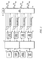
- FIG. 1 A block diagram of an implantable cardiac rhythm management device or pulse generator having multiple sensing and pacing channels is shown in Fig. 1 .
- Pacing of the heart with an implanted device involves excitatory electrical stimulation of the heart by the delivery of pacing pulses to an electrode in electrical contact with the myocardium.
- the device is usually implanted subcutaneously on the patient's chest, and is connected to electrodes by leads threaded through the vessels of the upper venous system into the heart.
- An electrode can be incorporated into a sensing channel that generates an electrogram signal representing cardiac electrical activity at the electrode site and/or incorporated into a pacing channel for delivering pacing pulses to the site.
- the controller of the device in Fig. 1 is made up of a microprocessor 10 communicating with a memory 12 via a bidirectional data bus, where the memory 12 typically comprises a ROM (read-only memory) and/or a RAM (random-access memory).
- the controller could be implemented by other types of logic circuitry (e.g., discrete components or programmable logic arrays) using a state machine type of design, but a microprocessor-based system is preferable.
- the programming of a controller should be taken to refer to either discrete logic circuitry configured to perform particular functions or to the code executed by a microprocessor.
- the controller is capable of operating the pacemaker in a number of programmed modes where a programmed mode defines how pacing pulses are output in response to sensed events and expiration of time intervals.
- a telemetry interface 80 is provided for communicating with an external programmer 300.
- the external programmer is a computerized device with an associated display and input means that can interrogate the pacemaker and receive stored data as well as directly adjust the operating parameters of the pacemaker. As described below, in certain embodiments of a system for setting pacing parameters, the external programmer may be utilized for computing optimal pacing parameters from data received from the implantable device over the telemetry link which can then be set automatically or presented to a clinician in the form of recommendations.
- the embodiment shown in Fig. 1 has four sensing/pacing channels, where a pacing channel is made up of a pulse generator connected to an electrode while a sensing channel is made up of the sense amplifier connected to an electrode.
- a MOS switching network 70 controlled by the microprocessor is used to switch the electrodes from the input of a sense amplifier to the output of a pulse generator.
- the switching network 70 also allows the sensing and pacing channels to be configured by the controller with different combinations of the available electrodes.
- the channels may be configured as either atrial or ventricular channels allowing the device to deliver conventional ventricular single-site pacing with or without atrial tracking, biventricular pacing, or multi-site pacing of a single chamber.
- a left atrial (LA) sensing/pacing channel includes ring electrode 53a and tip electrode 53b of bipolar lead 53c, sense amplifier 51, pulse generator 52, and a channel interface 50
- a right atrial (RA) sensing/pacing channel includes ring electrode 43a and tip electrode 43b of bipolar lead 43c, sense amplifier 41, pulse generator 42, and a channel interface 40
- a right ventricular (RV) sensing/pacing channel includes ring electrode 23a and tip electrode 23b of bipolar lead 23c, sense amplifier 21, pulse generator 22, and a channel interface 20
- a left ventricular (LV) sensing/pacing channel includes ring electrode 33a and tip electrode 33b of bipolar lead 33c, sense amplifier 31, pulse generator 32, and a channel interface 30.
- the channel interfaces communicate bi-directionally with a port of microprocessor 10 and include analog-to-digital converters for digitizing sensing signal inputs from the sensing amplifiers, registers that can be written to for adjusting the gain and threshold values of the sensing amplifiers, and registers for controlling the output of pacing pulses and/or changing the pacing pulse amplitude.
- the device is equipped with bipolar leads that include two electrodes which are used for outputting a pacing pulse and/or sensing intrinsic activity. Other embodiments may employ unipolar leads with single electrodes for sensing and pacing.
- the switching network 70 may configure a channel for unipolar sensing or pacing by referencing an electrode of a unipolar or bipolar lead with the device housing or can 60.
- the controller controls the overall operation of the device in accordance with programmed instructions stored in memory.
- the controller interprets electrogram signals from the sensing channels and controls the delivery of paces in accordance with a pacing mode.
- An exertion level sensor 330 e.g., an accelerometer, a minute ventilation sensor, or other sensor that measures a parameter related to metabolic demand
- the sensing circuitry of the device generates atrial and ventricular electrogram signals from the voltages sensed by the electrodes of a particular channel.
- An electrogram is analogous to a surface EKG and indicates the time course and amplitude of cardiac depolarization and repolarization that occurs during either an intrinsic or paced beat.
- an electrogram signal in an atrial or ventricular sensing channel exceeds a specified threshold, the controller detects an atrial or ventricular sense, respectively, which pacing algorithms may employ to trigger or inhibit pacing.
- the exertion level sensor is a minute ventilation sensor which includes an exciter and an impedance measuring circuit.
- the exciter supplies excitation current of a specified amplitude (e.g., as a pulse waveform with constant amplitude) to excitation electrodes that are disposed in the thorax.
- Voltage sense electrodes are disposed in a selected region of the thorax so that the potential difference between the electrodes while excitation current is supplied is representative of the transthoracic impedance between the voltage sense electrodes.
- the conductive housing or can may be used as one of the voltage sense electrodes.
- the impedance measuring circuitry processes the voltage sense signal from the voltage sense electrodes to derive the impedance signal.
- impedance signal allows the derivation of signal representing respiratory activity and/or cardiac blood volume, depending upon the location the voltage sense electrodes in the thorax or cardiac anatomy.
- the impedance signal is filtered to remove the respiratory component, the result is a signal that is representative of blood volume in the heart at any point in time, thus allowing the computation of stroke volume and, when combined with heart rate, computation of cardiac output.
- Bradycardia pacing modes refer to pacing algorithms used to pace the atria and/or ventricles in a manner that enforces a certain minimum heart rate. Because of the risk of inducing an arrhythmia with asynchronous pacing, most pacemakers for treating bradycardia are programmed to operate synchronously in a so-called demand mode where sensed cardiac events occurring within a defined interval either trigger or inhibit a pacing pulse. Inhibited demand pacing modes utilize escape intervals to control pacing in accordance with sensed intrinsic activity.
- a pacing pulse is delivered to a heart chamber during a cardiac cycle only after expiration of a defined escape interval during which no intrinsic beat by the chamber is detected.
- a ventricular escape interval for pacing the ventricles can be defined between ventricular events, referred to as the cardiac cycle (CC) interval with its inverse being the lower rate limit or LRL.
- the CC interval is restarted with each ventricular sense or pace.
- another ventricular escape interval is defined between atrial and ventricular events, referred to as the atrio-ventricular pacing delay interval or AVD, where a ventricular pacing pulse is delivered upon expiration of the atrio-ventricular pacing delay interval if no ventricular sense occurs before.
- the atrio-ventricular pacing delay interval is triggered by an atrial sense and stopped by a ventricular sense or pace.
- An atrial escape interval can also be defined for pacing the atria either alone or in addition to pacing the ventricles.
- the atrio-ventricular delay interval is triggered by an atrial pace and stopped by a ventricular sense or pace.
- Atrial tracking and AV sequential pacing are commonly combined so that an AVD starts with either an atrial pace or sense.
- the AVD may be the same or different in the cases of atrial tracking and AV sequential pacing.
- cardiac resynchronization therapy is pacing stimulation applied to one or more heart chambers in a manner that compensates for conduction delays.
- Ventricular resynchronization pacing is useful in treating heart failure in patients with interventricular or intraventricular conduction defects because, although not directly inotropic, resynchronization results in a more coordinated contraction of the ventricles with improved pumping efficiency and increased cardiac output.
- Ventricular resynchronization can be achieved in certain patients by pacing at a single unconventional site, such as the left ventricle instead of the right ventricle in patients with left ventricular conduction defects.
- Resynchronization pacing may also involve biventricular pacing with the paces to right and left ventricles delivered either simultaneously or sequentially, with the interval between the paces termed the biventricular offset (BVO) interval (also sometimes referred to as the LV offset (LVO) interval or VV delay).
- BVO biventricular offset
- LVO LV offset
- VV delay the interval between the paces termed the biventricular offset (BVO) interval (also sometimes referred to as the LV offset (LVO) interval or VV delay).
- BVO biventricular offset
- LVO LV offset
- right atrial paces and senses trigger an AVD interval which upon expiration results in a pace to one of the ventricles and which is stopped by a right ventricular sense.
- the contralateral ventricular pace is delivered at the specified BVO interval with respect to expiration of the AVD interval.
- Cardiac resynchronization therapy is most commonly applied in the treatment of patients with heart failure due to left ventricular dysfunction which is either caused by or contributed to by left ventricular conduction abnormalities.
- the left ventricle or parts of the left ventricle contract later than normal during systole which thereby impairs pumping efficiency. This can occur during intrinsic beats and during paced beats when only the right ventricle is paced.
- pacing therapy is applied such that the left ventricle or a portion of the left ventricle is pre-excited relative to when it would become depolarized during an intrinsic or right ventricle-only paced beat.
- Optimal pre-excitation of the left ventricle in a given patient may be obtained with biventricular pacing or with left ventricular-only pacing.
- some patients have a right ventricular conduction deficit such as right bundle branch block and require pre-excitation of the right ventricle in order achieve synchronization of their ventricular contractions.
- an atrial conduction deficit exists such that left atrio-ventricular synchrony does not occur during intrinsic beats even if the intrinsic atrio-ventricular interval as measured from a right atrial sense to a right ventricular sense is normal. This is exasperated by right atrial pacing and the common location of right atrial appendage pacing. Measurement of the inter-atrial conduction times has demonstrated an increase when right atrial pacing as compared with conduction of an intrinsic atrial event. Additionally there may be an abnormal conduction delay between atria in up to 20 % of CRT patients. A primary aspect of the present disclosure involves determining if such an atrial conduction deficit exists and adjusting pacing parameters accordingly.
- One way of determining whether an atrial conduction deficit exists is to measure the interval between a right atrial sense or pace and a left atrial sense, referred to as the RA-LA interval, as described in co-pending application Serial No. 10/920,698 , entitled "BIATRIAL PACING OPTIMIZATION FOR BIVENTRICULAR PACING".
- Measurement of the LA-LV interval may be implemented by an implantable device for delivering CRT such as illustrated in Fig. 1 which has sensing/pacing channels for both atria and both ventricles.
- an LA lead/catheter is placed either directly in the left atrium or at the upper inter-atrial septum (e.g., Backman's bundle region).
- the LV lead is then placed using a standard approach (e.g., in the coronary sinus or a cardiac vein).
- the LA-LV interval may then be measured as the time between senses generated by the electrodes of the LA lead/catheter and the LV lead during sinus rhythm and/or during pacing of the right atrium at one or more particular rates.
- a single coronary sinus (CS) lead with two sets of electrodes may be used.
- one or more electrodes will be at the distal side of the lead to sense or pace the LV, while there are one or more electrodes in the middle of the lead such that they will be disposed near the opening of the CS to sense or pace the left atrium.
- the LA-LV delay interval may then be measured as the time between senses generated by the distal and middle electrodes during sinus rhythm and/or during pacing of the right atrium at one or more particular rates.
- the LA-LV interval is measured during the LV lead implantation procedure.
- the LV lead is temporarily positioned at the midportion of the coronary sinus while the lead is being implanted in order to sense the left atrium.
- the RA lead is also positioned.
- the time interval between an RA sense or pace and an LA sense from the temporarily positioned LV is measured as the RA-LA interval.
- the LV lead is then further advanced through the CS to its final desired position for sensing the LV.
- the RA-LV delay is next measured as the interval between an RA sense and an LV sense.
- the implantable device is configured to deliver biventricular pacing in a manner specified by AVD and BVO intervals.
- An additional pacing parameter is also provided for pacing the left atrium, if necessary, referred to as the AAL interval, which is an escape interval triggered by a right atrial event and results in a left atrial pace upon expiration.
- the AAL interval is an escape interval triggered by a right atrial event and results in a left atrial pace upon expiration. If the measured LA-LV interval is less than a specified threshold amount, it can be surmised that a conduction deficit exists between the right and left atria, causing asynchrony between the left atrium and left ventricle.
- the device can therefore be configured to pace the left atrium at an AAL interval (where a zero AAL interval paces both atria simultaneously) which synchronizes left atrial and left ventricular contractions.
- the timing for left atrial pacing may be based upon left ventricular events. This involves pacing the left atrium at a specified offset interval VAL with respect to the time at which a left ventricular pace is delivered A negative VAL interval thus delivers a pace to the left atrium before the left ventricle is paced and may be used in non-atrial triggered and non-AV sequential modes as well atrial triggered and AV sequential pacing modes.
- left atrial pacing can based upon both right atrial and left ventricular events so that both AAL and VAL intervals are defined.
- pacing parameters affecting the manner and extent to which pre-excitation is applied must be specified.
- the objective of CRT is to improve a patient's cardiac pumping function, it is therefore normally delivered in an atrial-tracking and/or AV sequential mode and requires specification of AVD and BVO intervals which, ideally, result in the ventricles being synchronized during systole after being optimally preloaded during atrial systole. That is, both optimal interventricular synchrony and optimal atrio-ventricular synchrony are achieved.
- the AVD interval refers to the interval between an atrial event (i.e., a pace or sense in one of the atria, usually the right atrium) and the first ventricular pace which pre-excites one of the ventricles.
- the AVD interval may be the same or different depending upon whether it is initiated by an atrial sense or pace (i.e., in atrial tracking and AV sequential pacing modes, respectively),
- the pacing instant for the non-pre-excited ventricle is specified by the BVO interval so that it is paced at an interval AVD + BVO after the atrial event. It should be appreciated that specifying AVD and BVO intervals is the same as specifying a separate AVD interval for each ventricle, designated as AVDR for the right ventricle and AVDL for the left ventricle.
- the non-pre-excited ventricle In patients with intact and normally functioning AV conduction pathways to the non-pre-excited ventricle, the non-pre-excited ventricle will be paced, if at all, close to the time at which that ventricle is intrinsically activated in order to achieve optimal preloading. In patients with normal AV conduction to the non-pre-excited ventricle, the optimal AVD and BVO intervals are thus related to both the intrinsic atrio-ventricular interval and the amount of pre-excitation needed for one ventricle relative to the other (i.e., the extent of the ventricular conduction deficit).
- clinical hemodynamic testing may be performed after implantation where the parameters are varied as cardiac function is assessed.
- a patient may be given resynchronization stimulation while varying pre-excitation timing parameters in order to determine the values of the parameters that result in maximum cardiac performance, as determined by measuring a parameter reflective of cardiac function such as maximum left ventricular pressure change (dP/dt), arterial pulse pressure, or measurements of cardiac output.
- dP/dt maximum left ventricular pressure change
- dP/dt maximum left ventricular pressure change
- arterial pulse pressure or measurements of cardiac output.
- a variable related to cardiac output such as transthoracic impedance, is used to compute optimum values of resynchronization pacing parameters. In one embodiment, this allows dynamic changes in device behavior to occur in response to the patient's condition through cardiac remodeling, medication changes and physiologic changes.
- An implantable cardiac resynchronization device is configured to deliver biventricular pacing in an atrial tracking or AV sequential pacing mode with a specified atrio-ventricular (AVD) interval.
- the AVD interval (and/or BVO interval) is then varied while measuring a variable related to cardiac output such as transthoracic impedance or intracardiac ultrasound (either external or integral to the device system).
- the AVD interval can then be set to a value which maximizes the variable related to cardiac output.
- the AVD interval may be varied, for example, using a binary search algorithm to derive the value of the AVD interval which maximizes the variable related to cardiac output.
- an inter-atrial conduction delay which is greater than normal may make it necessary to pace the left atrium in order to achieve optimal synchronization of the left atrium and the left ventricle.
- the LA-LV delay interval is therefore measured by the techniques described above, with left atrial pacing initiated if the LA-LV interval exceeds a specified threshold Th1. Additionally following the optimization of the AV delay for maximum cardiac output, the LA-LV timing may be optimized in relationship to maximum cardiac output.
- a system for setting the pacing parameters includes an external programmer.
- a parameter related to cardiac output is measured by an implantable cardiac resynchronization device equipped with a transthoracic impedance sensor and transmitted to the external programmer via a wireless telemetry link. Either automatically or under the direction of the external programmer, the implantable device then varies the AVD and/or BVO intervals while measuring the variable related to cardiac output and measures the LA-LV interval during an intrinsic and/or right atrial paced cycle.
- the external programmer then automatically programs the implantable device with the computed optimum pacing parameter values, while in a semi-automated system the external programmer presents the computed optimum values to a clinician in the form of a recommendation.
- An automated system may also be made up of the implantable device alone which collects cardiac output data while varying the AVD and BVO intervals, measures the LA-LV interval and initiates left atrial pacing if necessary, determines the optimum parameter values which maximize cardiac output, and then sets the parameters accordingly.
- the external programmer presents the collected cardiac output data and corresponding AVD and BVO intervals, as well as the LA-LV interval to a clinician for evaluation.
- references to a system for computing or setting pacing parameters throughout this document should be taken to include any of the automated, semi-automated, or manual systems just described.
- Another manual system could incorporate manual measurement of CO with external cardiac ultrasound while the device or external programmer optimizes the pacing parameters in a step like fashion.
- Fig. 2 illustrates an exemplary algorithm for computing the optimal pacing parameters of an implantable cardiac rhythm management device for delivering biventricular pacing.
- the algorithm may be partially or wholly implemented as code executed by the device controller or by an external programmer.
- the implantable device may be equipped with sensing and pacing channels for both ventricles and both atria as shown in Fig. 1 .
- the device is programmed to deliver right and left ventricular paces separated by specified biventricular offset interval BVO and in an atrial tracking or AV sequential mode so that the ventricular paces are delivered at an atrio-ventricular delay interval AVD following an atrial event.
- the AVD and BVO intervals are either set to nominal initial values or are as set by a previous execution of the algorithm.
- the atrial rate (either paced or intrinsic) is measured and tested for stability. If the atrial rate is stable, the LA-LV interval is measured at step S3. The measured LA-LV interval may be either a single measurement or an average of LA-LV interval measurements taken over a number of beats.
- the LA-LV interval is compared with a specified threshold value Th1. If the LA-LV interval is less than Th1, left atrial pacing is initiated at step S5. This will initiate left atrial contraction preceding the left ventricular event mimicking the normal physiologic events. Since this is not a 'normal' heart, minor timing variations may improve cardiac efficiency.
- left atrial contraction may need to precede the left ventricular event by a greater amount than in the 'normal' healthy heart to allow full LA contraction and atrial augmentation of left ventricular filling.
- the algorithm then proceeds to step S6 where optimization subroutines are performed for the AVD and BVO intervals.
- the interval (either the AVD or BVO) is varied while a variable related to cardiac output is measured, with the optimum value of the interval selected as the interval value which results in maximum cardiac output.
- CRT may be delivered without left atrial pacing and with a conservative AVD value which pre-excites the left ventricle later than normal. If the patient has normal AV conduction to the right ventricle, the optimum AVD value will normally be very close to the intrinsic atrio-ventricular interval and cannot be lengthened beyond it in order to compensate for an inter-atrial conduction delay.
- the patient does not have intact native AV conduction such as complete AV block or a prolonged AV delay, it may be desirable to compensate for a prolonged inter-atrial delay with conservative AVD value rather than pacing the left atrium.
- a long AVD value is used to pre-excite the left ventricle later than would be considered normal so as to maintain LA-LV synchrony even with the delayed LA contraction.
- a long AVD value may also be found with a cardiac output maximizing algorithm for computing an optimal AVD value.
- the AVD optimization subroutine by finding the AVD value which produces maximum cardiac output, will give an AVD interval which is longer than the optimum AVD interval it would find if there were no inter-atrial delay.
- the optimization subroutine effectively adds the inter-atrial delay to the optimum AVD interval which would be found if there were no inter-atrial delay since it is synchrony between the left atria and ventricle that is most responsible for maximizing cardiac output.
- the algorithm may adjust an initial RA to LA timing (perhaps based on averaged measured patient values) through a step up/step down algorithm applied to either an AAL or VAL interval used to pace the left atrium, thus optimizing the LA-LV interval and additionally maximizing the cardiac output.
- the algorithm may also follow optimization of the AVD and LA-LV intervals with re-optimization of the AVD interval to confirm that it was not negatively affected by changing the inter-atrial timing.
- the algorithm illustrated in Fig. 2 may be performed periodically or upon command from an external programmer. In some situations, it may be desirable for the patient to remain in a steady state during optimization of pacing parameters. Such an optimization procedure may be performed, for example, in a physician's facility or automatically by the implantable device while the patient is sleeping. Optimization of pacing parameters may also be performed during exercise (treadmill testing) since it is expected that these values will change with heart rate. This would allow the computation of dynamic optimum AV delays and inter-atrial timing as occurs in the normal physiologic heart. In this manner optimum values for the AVD, BVO, and left atrial pacing intervals may be computed for a plurality of heart rate ranges.
- the algorithm may first determine which of a plurality of heart rate ranges corresponds to the current measured atrial rate. Optimum AVD, BVO, and left atrial pacing intervals are then computed as described above for that particular heart rate range. The device controller is then programmed to use those optimum AVD, BVO, and/or left atrial pacing interval values which have been computed for the current atrial rate.
Landscapes
- Health & Medical Sciences (AREA)
- Cardiology (AREA)
- Heart & Thoracic Surgery (AREA)
- Life Sciences & Earth Sciences (AREA)
- Engineering & Computer Science (AREA)
- Veterinary Medicine (AREA)
- Nuclear Medicine, Radiotherapy & Molecular Imaging (AREA)
- Radiology & Medical Imaging (AREA)
- Biomedical Technology (AREA)
- Animal Behavior & Ethology (AREA)
- General Health & Medical Sciences (AREA)
- Public Health (AREA)
- Physiology (AREA)
- Biophysics (AREA)
- Hospice & Palliative Care (AREA)
- Electrotherapy Devices (AREA)
- Measurement And Recording Of Electrical Phenomena And Electrical Characteristics Of The Living Body (AREA)
- Suspension Of Electric Lines Or Cables (AREA)
Claims (6)
- Système pour établir des paramètres de stimulation optimum pour délivrer à un patient une thérapie de resynchronisation cardiaque dans un mode de stimulation biventriculaire, comprenant :un dispositif de gestion de rythme cardiaque implantable pour délivrer une stimulation biventriculaire, dans lequel le dispositif est équipé de canaux de détection et de stimulation pour les deux oreillettes et les deux ventricules et est programmé pour délivrer des stimulations des ventricules gauche et droit séparées par un intervalle de Décalage Biventriculaire BVO spécifié et dans un mode suivi d'oreillette ou un mode séquentiel AV de telle sorte que les stimulations ventriculaires soient délivrées selon un intervalle de Retard Atrioventriculaire AVD à la suite d'un événement d'oreillette ;un capteur pour mesurer une sortie cardiaque ;un processeur programmé pour :1) établir des intervalles AVD et BVO à des valeurs initiales ou des valeurs établies par une exécution précédente ;2) mesurer et tester la stabilité d'une fréquence d'oreillette ;3) mesurer l'intervalle temporel entre une contraction d'oreillette gauche et une contraction de ventricule gauche chez le patient, cet intervalle étant appelé LA-LV ;4) comparer l'intervalle LA-LV à un seuil spécifié Th1 et identifier le patient comme présentant un retard inter-oreillette prolongé si l'intervalle LA-LV est inférieur au seuil Th1 ;5) initier une stimulation d'oreillette gauche si l'intervalle LA-LV est inférieur au seuil Th1 ;6) optimiser les intervalles AVD et BVO en faisant varier l'intervalle AVD ou BVO tout en mesurant une variable rapportée à la sortie cardiaque et en calculant les intervalles AVD ou BVO optimum en tant que valeur de l'intervalle AVD ou BVO qui maximise la variable rapportée à la sortie cardiaque ;7) optimiser l'intervalle LA-LV en réglant un intervalle de stimulation utilisé pour stimuler l'oreillette gauche, dans lequel ledit intervalle de stimulation est soit le Retard Oreillette-Oreillette AAL qui suit une détection ou stimulation d'oreillette droite, soit un intervalle de décalage spécifié VAL par rapport à l'instant auquel une stimulation de ventricule gauche est délivrée ; et8) re-optimiser l'intervalle AVD afin de confirmer qu'il n'a pas été affecté négativement par la modification du cadencement inter-oreillette.
- Système selon la revendication 1, dans lequel le processeur est un contrôleur du dispositif implantable.
- Système selon la revendication 1, dans lequel le processeur est un programmateur externe configuré pour communiquer avec le dispositif implantable via une liaison de télémétrie sans fil.
- Système selon la revendication 1, dans lequel l'intervalle AAL spécifié varie en fonction du rythme cardiaque.
- Système selon la revendication 1, dans lequel l'intervalle de décalage spécifié varie en fonction du rythme cardiaque.
- Système selon la revendication 1, dans lequel le processeur est en outre programmé pour :calculer des intervalles AVD, BVO et de stimulation d'oreillette gauche optimum pour une pluralité de plages de rythmes cardiaques ; etdéterminer celle de la pluralité de plages de rythmes cardiaques qui correspond à la fréquence d'oreillette mesurée courante et sélectionner l'intervalle AVD, BVO et de stimulation d'oreillette gauche correspondant optimisé pour cette plage de rythmes cardiaques.
Applications Claiming Priority (2)
| Application Number | Priority Date | Filing Date | Title |
|---|---|---|---|
| US11/113,809 US20060041279A1 (en) | 2004-08-18 | 2005-04-25 | Detection and treatment of prolonged inter-atrial delay in cardiac resynchronization patients |
| PCT/US2006/010287 WO2006115638A1 (fr) | 2005-04-25 | 2006-03-22 | Appareil de traitement d'un retard inter-auriculaire prolonge |
Publications (2)
| Publication Number | Publication Date |
|---|---|
| EP1885439A1 EP1885439A1 (fr) | 2008-02-13 |
| EP1885439B1 true EP1885439B1 (fr) | 2010-12-08 |
Family
ID=36699281
Family Applications (1)
| Application Number | Title | Priority Date | Filing Date |
|---|---|---|---|
| EP06739182A Not-in-force EP1885439B1 (fr) | 2005-04-25 | 2006-03-22 | Appareil de traitement d'un retard inter-auriculaire prolonge |
Country Status (6)
| Country | Link |
|---|---|
| US (1) | US20060041279A1 (fr) |
| EP (1) | EP1885439B1 (fr) |
| JP (1) | JP5172659B2 (fr) |
| AT (1) | ATE490803T1 (fr) |
| DE (1) | DE602006018727D1 (fr) |
| WO (1) | WO2006115638A1 (fr) |
Families Citing this family (13)
| Publication number | Priority date | Publication date | Assignee | Title |
|---|---|---|---|---|
| US7123960B2 (en) | 2003-12-22 | 2006-10-17 | Cardiac Pacemakers, Inc. | Method and system for delivering cardiac resynchronization therapy with variable atrio-ventricular delay |
| US7389141B2 (en) * | 2003-12-22 | 2008-06-17 | Cardiac Pacemakers, Inc. | Biatrial pacing optimization for biventricular pacing |
| US20060178705A1 (en) * | 2005-02-10 | 2006-08-10 | Paul Janssen | Heart rate variance cardiac pacemaker |
| US8301250B2 (en) * | 2006-07-17 | 2012-10-30 | Rami Rom | Intelligent control system for adaptive cardiac resynchronization therapy device |
| US7890172B2 (en) * | 2007-01-18 | 2011-02-15 | Cardiac Pacemakers, Inc. | Pacing output configuration selection for cardiac resynchronization therapy patients |
| US9375578B2 (en) * | 2008-07-23 | 2016-06-28 | Medtronic, Inc. | Cardiac pacing methods and apparatus |
| EP2903510B1 (fr) * | 2012-10-02 | 2019-12-04 | NewStim, Inc. | Stimulation ventriculaire dans des applications cardiaques |
| US9233251B2 (en) | 2014-01-16 | 2016-01-12 | Medtronic, Inc. | Bi-atrial synchronized left ventricular cardiac pacing |
| KR101893299B1 (ko) * | 2017-05-15 | 2018-08-30 | (주)나눔테크 | Egm자료를 이용한 심장박동기용 시험장치 |
| WO2018231939A1 (fr) | 2017-06-16 | 2018-12-20 | Cardiac Pacemakers, Inc. | Commande dynamique de thérapie d'insuffisance cardiaque |
| JP7013018B2 (ja) | 2018-05-16 | 2022-01-31 | 安立計器株式会社 | 接触式温度計 |
| US11311731B2 (en) | 2019-04-12 | 2022-04-26 | Cardiac Pacemakers, Inc. | Cardiac resynchronization therapy heart sound response characterization |
| US11318313B2 (en) | 2019-04-12 | 2022-05-03 | Cardiac Pacemakers, Inc. | Response-based cardiac resynchronization therapy parameter determination |
Family Cites Families (23)
| Publication number | Priority date | Publication date | Assignee | Title |
|---|---|---|---|---|
| US5190035A (en) * | 1981-06-18 | 1993-03-02 | Cardiac Pacemakers, Inc. | Biomedical method and apparatus for controlling the administration of therapy to a patient in response to changes in physiological demand |
| US5836987A (en) * | 1995-11-15 | 1998-11-17 | Cardiac Pacemakers, Inc. | Apparatus and method for optimizing cardiac performance by determining the optimal timing interval from an accelerometer signal |
| US5700283A (en) * | 1996-11-25 | 1997-12-23 | Cardiac Pacemakers, Inc. | Method and apparatus for pacing patients with severe congestive heart failure |
| US6070100A (en) * | 1997-12-15 | 2000-05-30 | Medtronic Inc. | Pacing system for optimizing cardiac output and determining heart condition |
| US6076015A (en) * | 1998-02-27 | 2000-06-13 | Cardiac Pacemakers, Inc. | Rate adaptive cardiac rhythm management device using transthoracic impedance |
| US5902324A (en) * | 1998-04-28 | 1999-05-11 | Medtronic, Inc. | Bi-atrial and/or bi-ventricular sequential cardiac pacing systems |
| US7158830B2 (en) * | 1998-05-08 | 2007-01-02 | Cardiac Pacemakers, Inc. | Method and apparatus for optimizing stroke volume during DDD resynchronization therapy using adjustable atrio-ventricular delays |
| FR2802433B1 (fr) * | 1999-12-17 | 2002-05-17 | Ela Medical Sa | Dispositif medical, implantable actif, notamment stimulateur cardiaque, defibrillateur et/ou cardiovecteur du type multisite comportant des moyens de resynchronisation des ventricules |
| US6937895B1 (en) * | 2001-08-14 | 2005-08-30 | Pacesetter, Inc. | Multi-site cardiac stimulation device for controlling inter-chamber stimulation delay |
| US6507756B1 (en) * | 2000-04-03 | 2003-01-14 | Medtronic, Inc. | Dual chamber pacing system having time-adaptive AV delay |
| US6574506B2 (en) * | 2000-12-26 | 2003-06-03 | Cardiac Pacemakers, Inc. | System and method for timing synchronized pacing |
| US6477417B1 (en) * | 2001-04-12 | 2002-11-05 | Pacesetter, Inc. | System and method for automatically selecting electrode polarity during sensing and stimulation |
| US6711437B2 (en) * | 2001-07-30 | 2004-03-23 | Medtronic, Inc. | Pacing channel isolation in multi-site cardiac pacing systems |
| US6871096B2 (en) * | 2001-10-26 | 2005-03-22 | Medtronic, Inc. | System and method for bi-ventricular fusion pacing |
| US6904320B2 (en) * | 2002-02-14 | 2005-06-07 | Pacesetter, Inc. | Sleep apnea therapy device using dynamic overdrive pacing |
| US7228174B2 (en) * | 2002-04-29 | 2007-06-05 | Medtronics, Inc. | Algorithm for the automatic determination of optimal AV an VV intervals |
| US7206634B2 (en) * | 2002-07-26 | 2007-04-17 | Cardiac Pacemakers, Inc. | Method and apparatus for optimizing cardiac pumping performance |
| US7013176B2 (en) * | 2003-01-28 | 2006-03-14 | Cardiac Pacemakers, Inc. | Method and apparatus for setting pacing parameters in cardiac resynchronization therapy |
| US6871088B2 (en) * | 2003-03-20 | 2005-03-22 | Medtronic, Inc. | Method and apparatus for optimizing cardiac resynchronization therapy |
| US7203540B2 (en) * | 2003-12-22 | 2007-04-10 | Cardiac Pacemakers, Inc. | Method and system for setting cardiac resynchronization therapy parameters |
| US7389141B2 (en) * | 2003-12-22 | 2008-06-17 | Cardiac Pacemakers, Inc. | Biatrial pacing optimization for biventricular pacing |
| US7194307B2 (en) * | 2003-12-22 | 2007-03-20 | Cardiac Pacemakers, Inc. | Pacing method and device for preserving native conduction system |
| US7123960B2 (en) * | 2003-12-22 | 2006-10-17 | Cardiac Pacemakers, Inc. | Method and system for delivering cardiac resynchronization therapy with variable atrio-ventricular delay |
-
2005
- 2005-04-25 US US11/113,809 patent/US20060041279A1/en not_active Abandoned
-
2006
- 2006-03-22 JP JP2008508847A patent/JP5172659B2/ja not_active Expired - Fee Related
- 2006-03-22 AT AT06739182T patent/ATE490803T1/de not_active IP Right Cessation
- 2006-03-22 DE DE602006018727T patent/DE602006018727D1/de active Active
- 2006-03-22 EP EP06739182A patent/EP1885439B1/fr not_active Not-in-force
- 2006-03-22 WO PCT/US2006/010287 patent/WO2006115638A1/fr active Application Filing
Also Published As
| Publication number | Publication date |
|---|---|
| DE602006018727D1 (de) | 2011-01-20 |
| US20060041279A1 (en) | 2006-02-23 |
| EP1885439A1 (fr) | 2008-02-13 |
| JP5172659B2 (ja) | 2013-03-27 |
| ATE490803T1 (de) | 2010-12-15 |
| JP2008538981A (ja) | 2008-11-13 |
| WO2006115638A1 (fr) | 2006-11-02 |
Similar Documents
| Publication | Publication Date | Title |
|---|---|---|
| EP1885439B1 (fr) | Appareil de traitement d'un retard inter-auriculaire prolonge | |
| US7389141B2 (en) | Biatrial pacing optimization for biventricular pacing | |
| US8626289B2 (en) | Method and system for delivering cardiac resynchronization therapy with variable atrio-ventricular delay | |
| US8731660B2 (en) | Method and system for setting cardiac resynchronization therapy parameters | |
| EP1596934B1 (fr) | Appareil de reglage de parametres de stimulation | |
| EP1885441B1 (fr) | Dispositif pour traiter l'asynchronie cardiaque mecanique | |
| US7206634B2 (en) | Method and apparatus for optimizing cardiac pumping performance | |
| US6915160B2 (en) | Dynamically optimized multisite cardiac resynchronization device | |
| EP1703944A1 (fr) | Ajustement de parametres de stimulation biventriculaire sequentielle | |
| US7194307B2 (en) | Pacing method and device for preserving native conduction system |
Legal Events
| Date | Code | Title | Description |
|---|---|---|---|
| PUAI | Public reference made under article 153(3) epc to a published international application that has entered the european phase |
Free format text: ORIGINAL CODE: 0009012 |
|
| 17P | Request for examination filed |
Effective date: 20071106 |
|
| AK | Designated contracting states |
Kind code of ref document: A1 Designated state(s): AT BE BG CH CY CZ DE DK EE ES FI FR GB GR HU IE IS IT LI LT LU LV MC NL PL PT RO SE SI SK TR |
|
| RIN1 | Information on inventor provided before grant (corrected) |
Inventor name: DING, JIANG Inventor name: MORRIS, MILTON M. Inventor name: YU, YINGHONG |
|
| DAX | Request for extension of the european patent (deleted) | ||
| 17Q | First examination report despatched |
Effective date: 20090304 |
|
| GRAP | Despatch of communication of intention to grant a patent |
Free format text: ORIGINAL CODE: EPIDOSNIGR1 |
|
| GRAS | Grant fee paid |
Free format text: ORIGINAL CODE: EPIDOSNIGR3 |
|
| GRAA | (expected) grant |
Free format text: ORIGINAL CODE: 0009210 |
|
| AK | Designated contracting states |
Kind code of ref document: B1 Designated state(s): AT BE BG CH CY CZ DE DK EE ES FI FR GB GR HU IE IS IT LI LT LU LV MC NL PL PT RO SE SI SK TR |
|
| REG | Reference to a national code |
Ref country code: GB Ref legal event code: FG4D |
|
| REG | Reference to a national code |
Ref country code: CH Ref legal event code: EP |
|
| REG | Reference to a national code |
Ref country code: IE Ref legal event code: FG4D |
|
| REF | Corresponds to: |
Ref document number: 602006018727 Country of ref document: DE Date of ref document: 20110120 Kind code of ref document: P |
|
| REG | Reference to a national code |
Ref country code: NL Ref legal event code: VDEP Effective date: 20101208 |
|
| PG25 | Lapsed in a contracting state [announced via postgrant information from national office to epo] |
Ref country code: LT Free format text: LAPSE BECAUSE OF FAILURE TO SUBMIT A TRANSLATION OF THE DESCRIPTION OR TO PAY THE FEE WITHIN THE PRESCRIBED TIME-LIMIT Effective date: 20101208 |
|
| LTIE | Lt: invalidation of european patent or patent extension |
Effective date: 20101208 |
|
| PG25 | Lapsed in a contracting state [announced via postgrant information from national office to epo] |
Ref country code: BG Free format text: LAPSE BECAUSE OF FAILURE TO SUBMIT A TRANSLATION OF THE DESCRIPTION OR TO PAY THE FEE WITHIN THE PRESCRIBED TIME-LIMIT Effective date: 20110308 Ref country code: AT Free format text: LAPSE BECAUSE OF FAILURE TO SUBMIT A TRANSLATION OF THE DESCRIPTION OR TO PAY THE FEE WITHIN THE PRESCRIBED TIME-LIMIT Effective date: 20101208 Ref country code: NL Free format text: LAPSE BECAUSE OF FAILURE TO SUBMIT A TRANSLATION OF THE DESCRIPTION OR TO PAY THE FEE WITHIN THE PRESCRIBED TIME-LIMIT Effective date: 20101208 Ref country code: FI Free format text: LAPSE BECAUSE OF FAILURE TO SUBMIT A TRANSLATION OF THE DESCRIPTION OR TO PAY THE FEE WITHIN THE PRESCRIBED TIME-LIMIT Effective date: 20101208 Ref country code: SE Free format text: LAPSE BECAUSE OF FAILURE TO SUBMIT A TRANSLATION OF THE DESCRIPTION OR TO PAY THE FEE WITHIN THE PRESCRIBED TIME-LIMIT Effective date: 20101208 Ref country code: CY Free format text: LAPSE BECAUSE OF FAILURE TO SUBMIT A TRANSLATION OF THE DESCRIPTION OR TO PAY THE FEE WITHIN THE PRESCRIBED TIME-LIMIT Effective date: 20101208 Ref country code: SI Free format text: LAPSE BECAUSE OF FAILURE TO SUBMIT A TRANSLATION OF THE DESCRIPTION OR TO PAY THE FEE WITHIN THE PRESCRIBED TIME-LIMIT Effective date: 20101208 Ref country code: LV Free format text: LAPSE BECAUSE OF FAILURE TO SUBMIT A TRANSLATION OF THE DESCRIPTION OR TO PAY THE FEE WITHIN THE PRESCRIBED TIME-LIMIT Effective date: 20101208 |
|
| PG25 | Lapsed in a contracting state [announced via postgrant information from national office to epo] |
Ref country code: ES Free format text: LAPSE BECAUSE OF FAILURE TO SUBMIT A TRANSLATION OF THE DESCRIPTION OR TO PAY THE FEE WITHIN THE PRESCRIBED TIME-LIMIT Effective date: 20110319 Ref country code: PT Free format text: LAPSE BECAUSE OF FAILURE TO SUBMIT A TRANSLATION OF THE DESCRIPTION OR TO PAY THE FEE WITHIN THE PRESCRIBED TIME-LIMIT Effective date: 20110408 Ref country code: BE Free format text: LAPSE BECAUSE OF FAILURE TO SUBMIT A TRANSLATION OF THE DESCRIPTION OR TO PAY THE FEE WITHIN THE PRESCRIBED TIME-LIMIT Effective date: 20101208 Ref country code: GR Free format text: LAPSE BECAUSE OF FAILURE TO SUBMIT A TRANSLATION OF THE DESCRIPTION OR TO PAY THE FEE WITHIN THE PRESCRIBED TIME-LIMIT Effective date: 20110309 Ref country code: IS Free format text: LAPSE BECAUSE OF FAILURE TO SUBMIT A TRANSLATION OF THE DESCRIPTION OR TO PAY THE FEE WITHIN THE PRESCRIBED TIME-LIMIT Effective date: 20110408 Ref country code: CZ Free format text: LAPSE BECAUSE OF FAILURE TO SUBMIT A TRANSLATION OF THE DESCRIPTION OR TO PAY THE FEE WITHIN THE PRESCRIBED TIME-LIMIT Effective date: 20101208 Ref country code: EE Free format text: LAPSE BECAUSE OF FAILURE TO SUBMIT A TRANSLATION OF THE DESCRIPTION OR TO PAY THE FEE WITHIN THE PRESCRIBED TIME-LIMIT Effective date: 20101208 |
|
| PG25 | Lapsed in a contracting state [announced via postgrant information from national office to epo] |
Ref country code: RO Free format text: LAPSE BECAUSE OF FAILURE TO SUBMIT A TRANSLATION OF THE DESCRIPTION OR TO PAY THE FEE WITHIN THE PRESCRIBED TIME-LIMIT Effective date: 20101208 Ref country code: SK Free format text: LAPSE BECAUSE OF FAILURE TO SUBMIT A TRANSLATION OF THE DESCRIPTION OR TO PAY THE FEE WITHIN THE PRESCRIBED TIME-LIMIT Effective date: 20101208 Ref country code: PL Free format text: LAPSE BECAUSE OF FAILURE TO SUBMIT A TRANSLATION OF THE DESCRIPTION OR TO PAY THE FEE WITHIN THE PRESCRIBED TIME-LIMIT Effective date: 20101208 |
|
| PLBE | No opposition filed within time limit |
Free format text: ORIGINAL CODE: 0009261 |
|
| STAA | Information on the status of an ep patent application or granted ep patent |
Free format text: STATUS: NO OPPOSITION FILED WITHIN TIME LIMIT |
|
| PG25 | Lapsed in a contracting state [announced via postgrant information from national office to epo] |
Ref country code: DK Free format text: LAPSE BECAUSE OF FAILURE TO SUBMIT A TRANSLATION OF THE DESCRIPTION OR TO PAY THE FEE WITHIN THE PRESCRIBED TIME-LIMIT Effective date: 20101208 Ref country code: MC Free format text: LAPSE BECAUSE OF NON-PAYMENT OF DUE FEES Effective date: 20110331 |
|
| REG | Reference to a national code |
Ref country code: CH Ref legal event code: PL |
|
| 26N | No opposition filed |
Effective date: 20110909 |
|
| GBPC | Gb: european patent ceased through non-payment of renewal fee |
Effective date: 20110322 |
|
| REG | Reference to a national code |
Ref country code: FR Ref legal event code: ST Effective date: 20111130 |
|
| REG | Reference to a national code |
Ref country code: IE Ref legal event code: MM4A |
|
| REG | Reference to a national code |
Ref country code: DE Ref legal event code: R097 Ref document number: 602006018727 Country of ref document: DE Effective date: 20110909 |
|
| PG25 | Lapsed in a contracting state [announced via postgrant information from national office to epo] |
Ref country code: LI Free format text: LAPSE BECAUSE OF NON-PAYMENT OF DUE FEES Effective date: 20110331 Ref country code: IE Free format text: LAPSE BECAUSE OF NON-PAYMENT OF DUE FEES Effective date: 20110322 Ref country code: CH Free format text: LAPSE BECAUSE OF NON-PAYMENT OF DUE FEES Effective date: 20110331 Ref country code: FR Free format text: LAPSE BECAUSE OF NON-PAYMENT OF DUE FEES Effective date: 20110331 |
|
| PG25 | Lapsed in a contracting state [announced via postgrant information from national office to epo] |
Ref country code: GB Free format text: LAPSE BECAUSE OF NON-PAYMENT OF DUE FEES Effective date: 20110322 |
|
| PG25 | Lapsed in a contracting state [announced via postgrant information from national office to epo] |
Ref country code: LU Free format text: LAPSE BECAUSE OF NON-PAYMENT OF DUE FEES Effective date: 20110322 |
|
| PG25 | Lapsed in a contracting state [announced via postgrant information from national office to epo] |
Ref country code: TR Free format text: LAPSE BECAUSE OF FAILURE TO SUBMIT A TRANSLATION OF THE DESCRIPTION OR TO PAY THE FEE WITHIN THE PRESCRIBED TIME-LIMIT Effective date: 20101208 |
|
| PG25 | Lapsed in a contracting state [announced via postgrant information from national office to epo] |
Ref country code: HU Free format text: LAPSE BECAUSE OF FAILURE TO SUBMIT A TRANSLATION OF THE DESCRIPTION OR TO PAY THE FEE WITHIN THE PRESCRIBED TIME-LIMIT Effective date: 20101208 |
|
| PGFP | Annual fee paid to national office [announced via postgrant information from national office to epo] |
Ref country code: DE Payment date: 20200310 Year of fee payment: 15 Ref country code: IT Payment date: 20200221 Year of fee payment: 15 |
|
| REG | Reference to a national code |
Ref country code: DE Ref legal event code: R119 Ref document number: 602006018727 Country of ref document: DE |
|
| PG25 | Lapsed in a contracting state [announced via postgrant information from national office to epo] |
Ref country code: DE Free format text: LAPSE BECAUSE OF NON-PAYMENT OF DUE FEES Effective date: 20211001 |
|
| PG25 | Lapsed in a contracting state [announced via postgrant information from national office to epo] |
Ref country code: IT Free format text: LAPSE BECAUSE OF NON-PAYMENT OF DUE FEES Effective date: 20210322 |