EP1885225B1 - Structure having a mouting means - Google Patents
Structure having a mouting means Download PDFInfo
- Publication number
- EP1885225B1 EP1885225B1 EP06743992.7A EP06743992A EP1885225B1 EP 1885225 B1 EP1885225 B1 EP 1885225B1 EP 06743992 A EP06743992 A EP 06743992A EP 1885225 B1 EP1885225 B1 EP 1885225B1
- Authority
- EP
- European Patent Office
- Prior art keywords
- intermediate member
- rotatable member
- rotatable
- suction means
- structural
- Prior art date
- Legal status (The legal status is an assumption and is not a legal conclusion. Google has not performed a legal analysis and makes no representation as to the accuracy of the status listed.)
- Expired - Lifetime
Links
Images

Classifications
-
- A—HUMAN NECESSITIES
- A47—FURNITURE; DOMESTIC ARTICLES OR APPLIANCES; COFFEE MILLS; SPICE MILLS; SUCTION CLEANERS IN GENERAL
- A47K—SANITARY EQUIPMENT; ACCESSORIES THEREFOR, e.g. TOILET ACCESSORIES
- A47K5/00—Holders or dispensers for soap, toothpaste or the like
- A47K5/18—Holders or dispensers for soap, toothpaste or the like for both soap and toothpaste or the like; in combination with holders for drinking glasses, toothbrushes, or the like ; Toothpaste dispensers; Dental care centers
-
- A—HUMAN NECESSITIES
- A47—FURNITURE; DOMESTIC ARTICLES OR APPLIANCES; COFFEE MILLS; SPICE MILLS; SUCTION CLEANERS IN GENERAL
- A47K—SANITARY EQUIPMENT; ACCESSORIES THEREFOR, e.g. TOILET ACCESSORIES
- A47K10/00—Body-drying implements; Toilet paper; Holders therefor
- A47K10/04—Towel racks; Towel rails; Towel rods; Towel rolls, e.g. rotatable
- A47K10/10—Towel racks; Towel rails; Towel rods; Towel rolls, e.g. rotatable characterised by being mounted on cabinets, walls, doors, or the like
-
- A—HUMAN NECESSITIES
- A47—FURNITURE; DOMESTIC ARTICLES OR APPLIANCES; COFFEE MILLS; SPICE MILLS; SUCTION CLEANERS IN GENERAL
- A47K—SANITARY EQUIPMENT; ACCESSORIES THEREFOR, e.g. TOILET ACCESSORIES
- A47K10/00—Body-drying implements; Toilet paper; Holders therefor
- A47K10/16—Paper towels; Toilet paper; Holders therefor
- A47K10/18—Holders; Receptacles
-
- F—MECHANICAL ENGINEERING; LIGHTING; HEATING; WEAPONS; BLASTING
- F16—ENGINEERING ELEMENTS AND UNITS; GENERAL MEASURES FOR PRODUCING AND MAINTAINING EFFECTIVE FUNCTIONING OF MACHINES OR INSTALLATIONS; THERMAL INSULATION IN GENERAL
- F16B—DEVICES FOR FASTENING OR SECURING CONSTRUCTIONAL ELEMENTS OR MACHINE PARTS TOGETHER, e.g. NAILS, BOLTS, CIRCLIPS, CLAMPS, CLIPS OR WEDGES; JOINTS OR JOINTING
- F16B47/00—Suction cups for attaching purposes; Equivalent means using adhesives
-
- A—HUMAN NECESSITIES
- A47—FURNITURE; DOMESTIC ARTICLES OR APPLIANCES; COFFEE MILLS; SPICE MILLS; SUCTION CLEANERS IN GENERAL
- A47K—SANITARY EQUIPMENT; ACCESSORIES THEREFOR, e.g. TOILET ACCESSORIES
- A47K2201/00—Details of connections of bathroom accessories, e.g. fixing soap or towel holder to a wall
Definitions
- the present invention relates to a structure having a mounting means for removable attachment to a surface.
- the present invention is particularly suitable for attachment to smooth surfaces, such as glazed tiles, plastic, steel or glass, such as are commonly found in kitchens and bathrooms.
- Mounting means for removable attachment to smooth surfaces in kitchens and bathrooms are well known. They typically comprise a suction means for contacting a smooth surface, in the form of a suction pad.
- British patent application no. GB2373019 discloses such a mounting means for removable attachment to a surface. It comprises a suction means for sealingly contacting a surface and pulling means attached to the suction means for drawing a part of the suction means away from the surface so that a partial vacuum is created between the suctions means and the surface.
- the pulling means comprises a substantially helical surface engaged with a corresponding substantially helical surface of a rotatable member.
- Rotation of the rotatable member causes the helical surfaces to move over one another, thereby drawing the pulling means and respective part of the suction means away from the surface.
- the intermediate member supports the rotatable member at a substantially fixed distance from the surface in use.
- There is a contact means (which is separate from the intermediate member) which extends beyond the suction means and which is for contacting the surface when in use, so that twisting moments caused by putting loads on the mounting means can be transferred directly to the wall surface without going through the intermediate member and therefore without tending to pull parts of the suctions means away from the wall.
- the rotatable member may have a boss on which structural members can be supported.
- the present inventor has realised that operation can be made easier by inserting a friction reducing member such as a washer between the rotatable member and the intermediate member. This can be obtained, surprisingly, without introducing flexibility or instability into the design which could affect its operation.
- the present invention provides a structure comprising mounting means for removable attachment to a substantially vertical surface and a structural member mounted on the mounting means, the mounting means comprising: suction means for sealingly contacting a surface, pulling means being attached to the suction means for drawing a part of the suction means away from the surface so that a partial vacuum is created between the suction means and the surface, the pulling means comprising a substantially helical or wedge shaped surface engaged with a corresponding substantially helical or wedge shaped surface of a rotatable member, whereby rotation of the rotatable member draws the pulling means and respective part of the suction means away from the surface, and an intermediate member for engaging the sealing part of the suction means, the intermediate member supporting the rotatable member), wherein the rotatable member comprises at least one bearing surface for sliding over the intermediate member and the bearing surface engages the intermediate member through a friction-reducing member, wherein the structural member is mounted in or on a part of the intermediate member which, in use, is closer to the vertical surface than the outermost part
- the mounting means of the present invention can be used for engagement with any suitable surface.
- it is for engagement with a smooth surface.
- the surface is of the type found in kitchens and bathrooms, for example gloss painted surfaces, metal surfaces, such as aluminium or steel, glass or glazed surfaces such as tiles or plastic such as perspex or PVC.
- the suction means of the invention preferably comprises a material which forms a good seal with a smooth surface and is preferably a thermoplastic material example PVC or a silicone composition.
- the suction means maybe of any suitable shape, but is preferably substantially circular in plan. It may have a slightly domed profile.
- the pulling means is attached to the suction means substantially in the centre thereof.
- the sealing part of the suction means comprises that portion of the suction means which includes a surface which forms a sealing contact with the smooth surface in use.
- the suction means of the invention should form a sealing contact with a smooth surface around a closed figure, for example a circle.
- the pulling means should of course contact the suction means within the space defined by the closed figure.
- the pulling means of the invention may be integrally formed with the suction means, however, it is sometimes found that the suction means is formed of a material which is not suitable for forming a pulling means, being too flexible.
- the pulling means may then be sealingly engaged with the suction means, for example by a way of adhesive or by a mechanical fit.
- the suction means preferably comprises a sealing surface, for contacting a surface to which the mounting is to be fixed and a second surface, opposed to the sealing surface.
- the second surface preferably comprises at least one structure for engaging the intermediate member, so that the intermediate member can be fixed with respect to the suction means.
- the structure may comprise a ridge.
- it is a substantially continuously extending ridge extending around the suction means.
- it extends in the region of the sealing part.
- the rotatable member of the invention may be made of any suitable shape, but is preferable substantially circular in plan. It is suitably formed of a relatively rigid material, such as metal or thermoplastic.
- the metal may comprise aluminium or aluminium alloy. It may be cast and/or machined. It may comprise a thermoplastic material, for example polypropylene or polyethylene.
- the rotatable member is suitably of a diameter of 2cm or more, preferably 3 cm or more and most preferably 4 cm or more.
- the rotatable member is preferably of a generally circular configuration.
- the present inventor has further realised that the operation of the mounting means can be made easier if at least part of the rotatable member is of larger dimension than a part of the intermediate member adjacent to it, because of the greater leverage obtained. Further, this arrangement can be retained even when the structural member is mounted in the intermediate member. The user's fingers can still operate the rotatable member without getting caught in the structural member.
- At least part of the rotatable member extends beyond a part of the intermediate member which is adjacent to the rotatable member in a dimension normal to the axis of rotation of the rotatable member.
- the rotatable member comprises at least one bearing surface for sliding over the intermediate member.
- the bearing surface engages the intermediate surface through a friction reducing member such as a washer.
- the bearing surface may engage the intermediate surface through clip means, which may also function as a friction reducing member.
- the friction reducing member such as a washer may be formed of any suitable material, preferably, it is formed of a synthetic polymeric material for example an acetate based polymeric material. It should be able to withstand the loads applied during use.
- the friction reducing member may have any suitable shape but is preferably in the form of a laminar material, which is of thickness less than 15mm, preferably less than 10mm. It is preferably substantially circular in plan.
- the friction-reducing member may be fixed to the intermediate member or fixed to the rotatable member. It may be permanently fixed or releasably fixed. For example, it may have a screw threaded bore which is screwed onto the pulling means. There may be resilient structures formed on one of the friction reducing member and the member to which it is fixed, for example at least one hook for engaging at least one latch formation. Preferably, the friction reducing member has a resilient formation for engaging in a central hole of the intermediate member. These arrangements may allow the friction-reducing member to act as a clip means.
- the bearing surface is preferably located at a relatively large radius. Preferably, it is located at a radius at least 1 cm and preferably at least 1.5 cm. It may be coincident with the outer rim of the rotatable member. Preferably, however, it is located at a position displaced radially inwardly from the outer rim of the rotatable member by at least 1 mm and preferably at least 2 mm. This is so that the bearing part contacts the intermediate member at a part of the intermediate member which is also displaced inwardly from its edge and which is accordingly stable and strong.
- the bearing surface preferably comprises a substantially closed annular surface.
- the bearing surface may be a continuous formation with the outer rim of the rotatable member or it may be displaced away from the outer rim of the rotatable member.
- the intermediate member is suitably made of a metal or thermoplastic material preferably, it is formed of a metal such as aluminium or aluminium alloy. It may be cast and/or machined. It may be formed of thermoplastic material such as polyethylene or polypropylene.
- the intermediate member contacts the suction means in the sealing part thereof, so that the suction means will be firmly pushed into contact with the surface to improve the seal.
- the contact with the surface is preferably provided by the suction means only or by the suction means and a part of the structure which is mounted on the mounting means.
- the intermediate member and the rotatable member do not contact the surface.
- the mounting means of the invention may be of any suitable size.
- the suction means, intermediate member and rotatable member may be each be circular and each of diameter up to about 10 cm, more preferably up to about 8cm being most preferably around 3-5 cm in diameter.
- the suction means may provide a contact area in the range 20-80 mm 2 , more preferably 20-40mm 2 .
- a structural member can be held relatively close to the wall by mounting it in the intermediate member, rather than on the outside of the rotatable member. Further, the structure can be protected from shock loads by mounting the structural member relatively loosely in the intermediate member. Accordingly, the structural member is preferably mounted in the intermediate member. Any suitable structure may be provided which preferably does not grip the structural member, so that it can move. The structural member is preferably able to move in at least one dimension. There is preferably at least one degree of freedom of movement whereby shocks may be absorbed.
- the structural member is only able to move in one dimension, it is preferable that that dimension is not parallel to the vertical surface or, equivalently, the plane of contact of the suction means. This is because the forces most likely to dislodge the device from the vertical surface extend in a direction which is not parallel to the surface and it is desired to be able to move to accommodate such shocks.
- the structural member is mounted in or on a part of the intermediate member which, in use, is
- the weight of the structural member is transferred directly to the intermediate member.
- the weight is not transmitted through the rotatable member.
- a part of the structural member will contact the vertical surface so that a part of the weight of the structural member is supported by reaction forces (suitably frictional forces) at the vertical surface.
- reaction forces suitably frictional forces
- the whole weight of the structural member is taken by the intermediate member and the vertical surface together.
- the structural member is preferably rigid. Preferably, it is of the sufficient stiffness to be able to carry the weight of at least of a conventional bar of soap or a toilet roll.
- the structural member may make resilient contact with the intermediate member, and is preferably capable of being displaced under light loads for example loads in excess of 1 gram force more preferably in excess of 5 gram force.
- the structural member may be engaged with the intermediate member by an engagement portion which is received in an engagement recess of the intermediate member.
- the engagement recess of the intermediate member is preferably larger than the engagement portion of the structural member in at least one dimension.
- the engagement portion may comprise a suitable structure, for example stub or arm sections.
- the engagement portion may extend into the engagement recess of the intermediate member and terminate in the engagement recess, or it may extend through the engagement recess.
- the engagement recess is a continuously extending recess which extends through the intermediate member. This can allow the engagement structure to be slidably mounted on the intermediate member.
- close it is meant that the part of the intermediate member to which the structural member is attached is closer to the vertical surface, in use than the outermost part of the rotatable member.
- all or part of the weight of the structural member is transferred directly to the intermediate member. The weight is not transmitted through the rotatable member.
- a part of the structural member will contact the vertical surface so that a part of the weight of the structural member is supported by reaction forces (suitably frictional forces) at the vertical surface.
- reaction forces suitably frictional forces
- the whole weight of the structural member is taken by the intermediate member and the vertical surface together.
- the structural member is preferably rigid. Preferably, it is of the sufficient stiffness to be able to carry the weight of at least of a conventional bar of soap or a toilet roll.
- the structural member may make resilient contact with the intermediate member, and is preferably capable of being displaced under light loads for example loads in excess of 1 gram force more preferably in excess of 5 gram force.
- the structural member may be engaged with the intermediate member by an engagement portion which is received in an engagement recess of the intermediate member.
- the engagement recess of the intermediate member is preferably larger than the engagement portion of the structural member in at least one dimension.
- the engagement portion may comprise a suitable structure, for example stub or arm sections.
- the engagement portion may extend into the engagement recess of the intermediate member and terminate in the engagement recess, or it may extend through the engagement recess.
- the engagement recess is a continuously extending recess which extends through the intermediate member. This can allow the engagement structure to be slidably mounted on the intermediate member.
- the structural member may comprise any suitable structure. It may comprise a structural member for engaging other structures. However, it is particularly preferred that it comprises at least one of a toilet roll holder arm, a structural component on a shelf, basket or box, or a towel holder.
- a stop member may be provided on one of the engagement portion and engagement recess, engagable with a stop surface of the other component. This can prevent the structural member being disengaged unintentionally from the intermediate member.
- the structural member comprises a curved edge of a basket, the engagement recess being of sufficient size that it will engage with the curved edge and allow the curved edge to slide through the engagement recess.
- a basket can be mounted adjacent to a corner between two adjacent vertical walls, the position of the mounting member being adjusted along the curved edge of the basket to optimise the support.
- the engagement recess of the intermediate member may be closed on at least one face by at least one of a friction reducing member, a clip means or the rotatable member.
- the friction reducing member may be releasably fixed to intermediate member as described above.
- the friction reducing member which is releasably fixed to the intermediate member may provide a clip means. This allows the entire assembly to be separated into components which can then be reassembled when required.
- the present invention provides a kit of parts, comprising at least one mounting means according to the invention and at least two structural members, each of which is engageable with the intermediate member to provide a mounting means according to the present invention. In this way, a user can select the desired structure and assemble the components appropriately.
- the kit may further comprise a plurality of different intermediate members, each of which is engageable with a different design of structural member.
- the structural member comprises an engagement portion which is received in an engagement recess formed in the intermediate member, at least one face of the engagement recess being closed by a washer, the washer comprising a screw thread so that it is engageable with the screw thread of the pulling means.
- the washer can be screwed on to the pulling means to hold the engagement portion of the structural member in the engagement recess before the rotatable member is put in position.
- the engagement portion may comprise a rod of diameter in the range 3-10 mm and the engagement recess may comprise a slot of a diameter which is slightly larger, being for example 2-5 mm larger than the engagement portion.
- the mounting means of the present invention can support loads of 9-10 kilograms, which extend for a maximum extent of up to 100 mm preferably up to 80 mm from a wall, in use.
- the structure comprises a structural member and a mounting means
- the mounting means comprising a rotatable member and an intermediate member which are separable during assembly and which hold between them the structural member
- assembly can be complicated as the user will have to support each of intermediate member, the structural member and the rotatable member, which can be difficult with only two hands.
- a clip means can be provided for temporarily holding the structural member with respect to the one of the rotatable member or intermediate member during assembly, before the intermediate member and rotatable member are sufficiently engaged to provide full support for the structural member.
- the clip means is releasably engageable with at least one of the rotatable member and intermediate member for holding the structural member thereto during assembly.
- the clip means may comprise any suitable design. Preferably, it is for temporarily fixing the structural member to the intermediate member. It may be formed of any suitable material, for example a resiliently deformable metal formation or a resiliently deformable synthetic material, such as thermoplastic.
- the clip means comprises a contact surface, for holding the structural member with respect to the intermediate member or rotatable member and a resilient grip, for engaging a part of the intermediate member or rotatable member. It is particularly preferred that the intermediate member should comprise a central hole, through which the pulling means of the suction means projects, the engaging part of the clip means engaging in the hole.
- the clip means comprises a central hole through which, in use, the pulling means will project, a plurality of teeth being formed around the hole, for engaging in the hole of the intermediate member.
- the teeth comprise undercut formations for forming a snap fit engagement with the hole on the intermediate member.
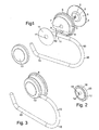
- Figure 1 shows a structure according to the present invention.
- a suction means 1 comprising a silicone rubber disc having a pulling means 2 projecting from the center.
- the suction means comprises a slight raised portion 3 in the middle which forms a secure connection between the pulling means 2 and the suction means 1.
- the pulling means 2 comprises a screw threaded shaft.
- the suction means 1 further comprises a raised ridge 4 around its perimeter.
- an intermediate member 5 of cast aluminium alloy It comprises a depending skirt 6 which has, on its underside, a ridge, (not shown) which is configured to exactly fit and engage the ridge 4 formed around the suction means 1.
- a central bore 7 through which the pulling means 2 of the suction means projects and which does not engage the pulling means.
- an engagement recess in the form of a longitudinally extending slot 8 which extends from one end of the intermediate member 5 to the other. It is of generally cylindrical form with one face removed. It comprises a part - arc shaped stop member 9 forming a stop.
- the structural member 10 in figure 1 comprises a toilet roll holder arm which is formed of stainless steel rod, the arm having a twisted U-shape.
- the engagement portion 11 which is of tubular shape of a diameter smaller than the diameter of the engagement recess 8. It comprises a stop surface 12 for engaging the stop 9 of the engagement recess 8, so that when in position, the arm 10 cannot be removed in the axial direction from the engagement slot 8.
- a washer of polyacyrylate material is provided.
- the washer 11 comprises a central bore 12 which, in the embodiment shown in figure 1 , fits over the pulling means 2 which extends through the bore 7 of the intermediate member 5 and does not engage the pulling means 2.
- a rotatable member 13 of a generally disc shape.
- the outer side of the rotatable member 13 is finished in contours for aesthetic appeal.
- the underside of the rotatable member is shown in figure 2 and comprises a boss 14 having a screw threaded bore 15 which is engageable with the pulling means 2 of the suction means 1.
- the outer periphery of the underside of the rotatable member 13 has an outer rim 16 and inner bearing surface 17 which is displaced by about 2mm from the rim 16.
- Figure 3 shows the mounting means of the present invention assembled.
- the suction means is completely covered by the intermediate member 5 which thereby protects it.
- the rotatable member 13 is shown in position.
- the outer diameter of the rotatable member 13 is very slightly larger than the outer diameter of the top of the intermediate member 5 which is adjacent to the rotatable member. In this way, a user's fingers will naturally grip the exterior surface of the rotatable member and will not catch on adjacent parts of the intermediate member 5.
- the structural member 10 is held loosely in a configuration in which it projects forwardly from the intermediate member 5.
- the mounting means of the present invention is placed, with the components assembled as shown in figure 3 with the suction member engaging a wall.
- the wall should have a smooth surface, for example being formed of glass, ceramic gloss paint or metal.
- the mounting means is pushed firmly into contact with the surface to obtain an initial grip then the user rotates the rotatable member 13.
- the screw thread 15 moves over the screw thread 2 of the pulling means, drawing the pulling means outward away from the wall.
- the central part of the suction means is pulled away from the wall to create a partial vacuum between the suction means of the wall, whereby a force is generated which the holds the mounting means in place.
- the structural member 10 will tend to rotate so that an inward portion 17 of the arm 10 will rest against the wall with the outer portion 19 protruding from it.
- the washer 11 reduces the friction between the rotatable member and the intermediate member 5. It also prevents scratching of surfaces between these two members.
- the arm 10 is held relatively loosely in the intermediate member so that any shock loads applied to the arm can be easily absorbed without applying twisting force to the mounting means.
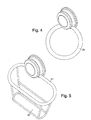
- Figure 4 shows a further embodiment of structure according to the present invention in which the suction means, intermediate member, rotatable member and washer are exactly as shown in figure 1 but the structural member comprises a substantially circular towel ring 20.
- the engagement portion of the towel ring will comprise a substantially tubular section with a stop slot exactly as shown for the arm 10 in figure 1 .
- Figure 5 shows a third embodiment of structure according to the present invention in which the mounting means comprising suction means, intermediate member, washer and rotatable member is exactly as shown in Figure 1 but the structural member comprises an upper circular section rim 21 of a basket 22 for containing articles for example for use in the bathroom.
- the circular suction rim 21 is configured so that it has no stop slot corresponding to the stop slot 12 shown in Figure 1 . Accordingly, it can slide along the recess 8. In this way, the mounting means can be fixed to a wall adjacent to corner with the basket pushed into the corner at any suitable position.
- FIG. 6 shows a sketch isometric view of a clip means, according to the invention.
- the clip means comprises a disk 23 and a central hole 24, through which the pulling means will project, in use.
- the hole is surrounded by eight resilient teeth 25.
- Each tooth comprises a wedge shaped leading section 26 with an undercut 27 and a stem 28.
- the clip means of Figure 6 can be used as the friction reducing member 11 of Figure 1 . It can perform exactly the same friction reducing function if it is made of suitable thermoplastic material.
- the teeth 25 are configured so that, when the clip means is pushed into engagement with the hole 7 of the intermediate member 5, the wedge section 26 ride smoothly into the hole.
- the stems 28 are of such a length that the teeth 25 can project all the way through the thickness of the hole 7, with the undercuts 27 clipping behind the rear surface of the intermediate member 5. In this way, the clip means will be sufficient to hold the structural member, for example 10, in position during assembly.
- the clip means is formed of thermoplastic material with sufficient stiffness to hold the weight of the structural member during assembly. This will make assembly of the whole mounting means easy and convenient.
- Figure 7 shows an embodiment of the intermediate member 29 suitable for use with the structural member 21 shown in Figure 5 . It comprises a slot 30, the base of which has an arc shaped profile so that the circular parts of the structural - 21 can ride smoothly along the slot 30, allowing the mounting means to be placed at any desired position on the structural member.
- a lightening hole 31 is provided to reduce the weight of the structure.
- Figure 8 shows a rear view of an intermediate member 32. This design may be applied to the intermediate member shown in Figure 1 or Figure 7 .
- a cutaway portion 33 is provided in the side of the formation which, on the outside of the intermediate member, defines the engaging means for the structural member. This is in order to allow the suction means to sit comfortably under the intermediate member 32.
- Figure 9 shows a yet further embodiment of intermediate member 34. It is shown engaged with the clip means of Figure 6 . It can be seen that it has a single hole 35 for engaging the stub of a hook shaped structural member 36. Lightening holes 37 are provided to reduce the weight of the formation. It can be seen that the hook is held temporarily so that the intermediate member 34 can be placed position over a suction member 13 with the pulling means 15 projecting through the central hole where it can be engaged with a rotatable member 13 in a simple straight-forward manner.
Landscapes
- Health & Medical Sciences (AREA)
- Public Health (AREA)
- Engineering & Computer Science (AREA)
- General Engineering & Computer Science (AREA)
- Mechanical Engineering (AREA)
- Dentistry (AREA)
- General Health & Medical Sciences (AREA)
- Hooks, Suction Cups, And Attachment By Adhesive Means (AREA)
Description
- The present invention relates to a structure having a mounting means for removable attachment to a surface. The present invention is particularly suitable for attachment to smooth surfaces, such as glazed tiles, plastic, steel or glass, such as are commonly found in kitchens and bathrooms.
- Mounting means for removable attachment to smooth surfaces in kitchens and bathrooms are well known. They typically comprise a suction means for contacting a smooth surface, in the form of a suction pad. British patent application no.
GB2373019 - The rotatable member may have a boss on which structural members can be supported.
- This is a successful and effective design of mounting means, but a number of problems have been encountered.
- A very strong grip can only be obtained if there is a powerful force on the pulling means. However, such forces tend to make operation of the mounting means difficult. Further, for maximum stability, it is desired that any structural member mounted using the mounting means should be held as close to the wall as possible and this is difficult with the existing design.
- The present inventor has realised that operation can be made easier by inserting a friction reducing member such as a washer between the rotatable member and the intermediate member. This can be obtained, surprisingly, without introducing flexibility or instability into the design which could affect its operation.
- Accordingly, the present invention provides a structure comprising mounting means for removable attachment to a substantially vertical surface and a structural member mounted on the mounting means, the mounting means comprising: suction means for sealingly contacting a surface, pulling means being attached to the suction means for drawing a part of the suction means away from the surface so that a partial vacuum is created between the suction means and the surface, the pulling means comprising a substantially helical or wedge shaped surface engaged with a corresponding substantially helical or wedge shaped surface of a rotatable member, whereby rotation of the rotatable member draws the pulling means and respective part of the suction means away from the surface, and an intermediate member for engaging the sealing part of the suction means, the intermediate member supporting the rotatable member), wherein the rotatable member comprises at least one bearing surface for sliding over the intermediate member and the bearing surface engages the intermediate member through a friction-reducing member, wherein the structural member is mounted in or on a part of the intermediate member which, in use, is closer to the vertical surface than the outermost part of the rotatable member, and wherein part of the structural member contacts the vertical surface so that a part of the weight of the structural member is supported by reaction forces at the vertical surface.
- Preferred and optional features of the present invention will be further described below.
- The mounting means of the present invention can be used for engagement with any suitable surface. Preferably, it is for engagement with a smooth surface. Preferably, the surface is of the type found in kitchens and bathrooms, for example gloss painted surfaces, metal surfaces, such as aluminium or steel, glass or glazed surfaces such as tiles or plastic such as perspex or PVC.
- The suction means of the invention preferably comprises a material which forms a good seal with a smooth surface and is preferably a thermoplastic material example PVC or a silicone composition. The suction means maybe of any suitable shape, but is preferably substantially circular in plan. It may have a slightly domed profile. Preferably, the pulling means is attached to the suction means substantially in the centre thereof.
- The sealing part of the suction means comprises that portion of the suction means which includes a surface which forms a sealing contact with the smooth surface in use.
- The suction means of the invention should form a sealing contact with a smooth surface around a closed figure, for example a circle. The pulling means should of course contact the suction means within the space defined by the closed figure.
- The pulling means of the invention may be integrally formed with the suction means, however, it is sometimes found that the suction means is formed of a material which is not suitable for forming a pulling means, being too flexible. The pulling means may then be sealingly engaged with the suction means, for example by a way of adhesive or by a mechanical fit.
- The suction means preferably comprises a sealing surface, for contacting a surface to which the mounting is to be fixed and a second surface, opposed to the sealing surface. The second surface preferably comprises at least one structure for engaging the intermediate member, so that the intermediate member can be fixed with respect to the suction means. For example, the structure may comprise a ridge. Preferably, it is a substantially continuously extending ridge extending around the suction means. Preferably, it extends in the region of the sealing part.
- The rotatable member of the invention may be made of any suitable shape, but is preferable substantially circular in plan. It is suitably formed of a relatively rigid material, such as metal or thermoplastic. The metal may comprise aluminium or aluminium alloy. It may be cast and/or machined. It may comprise a thermoplastic material, for example polypropylene or polyethylene. The rotatable member is suitably of a diameter of 2cm or more, preferably 3 cm or more and most preferably 4 cm or more.
- The rotatable member is preferably of a generally circular configuration.
- The present inventor has further realised that the operation of the mounting means can be made easier if at least part of the rotatable member is of larger dimension than a part of the intermediate member adjacent to it, because of the greater leverage obtained. Further, this arrangement can be retained even when the structural member is mounted in the intermediate member. The user's fingers can still operate the rotatable member without getting caught in the structural member.
- Preferably, at least part of the rotatable member extends beyond a part of the intermediate member which is adjacent to the rotatable member in a dimension normal to the axis of rotation of the rotatable member.
- The rotatable member comprises at least one bearing surface for sliding over the intermediate member. The bearing surface engages the intermediate surface through a friction reducing member such as a washer. The bearing surface may engage the intermediate surface through clip means, which may also function as a friction reducing member. The friction reducing member such as a washer may be formed of any suitable material, preferably, it is formed of a synthetic polymeric material for example an acetate based polymeric material. It should be able to withstand the loads applied during use.
- The friction reducing member may have any suitable shape but is preferably in the form of a laminar material, which is of thickness less than 15mm, preferably less than 10mm. It is preferably substantially circular in plan.
- The friction-reducing member may be fixed to the intermediate member or fixed to the rotatable member. It may be permanently fixed or releasably fixed. For example, it may have a screw threaded bore which is screwed onto the pulling means. There may be resilient structures formed on one of the friction reducing member and the member to which it is fixed, for example at least one hook for engaging at least one latch formation. Preferably, the friction reducing member has a resilient formation for engaging in a central hole of the intermediate member. These arrangements may allow the friction-reducing member to act as a clip means.
- The bearing surface is preferably located at a relatively large radius. Preferably, it is located at a radius at least 1 cm and preferably at least 1.5 cm. It may be coincident with the outer rim of the rotatable member. Preferably, however, it is located at a position displaced radially inwardly from the outer rim of the rotatable member by at least 1 mm and preferably at least 2 mm. This is so that the bearing part contacts the intermediate member at a part of the intermediate member which is also displaced inwardly from its edge and which is accordingly stable and strong.
- The bearing surface preferably comprises a substantially closed annular surface. The bearing surface may be a continuous formation with the outer rim of the rotatable member or it may be displaced away from the outer rim of the rotatable member.
- The intermediate member is suitably made of a metal or thermoplastic material preferably, it is formed of a metal such as aluminium or aluminium alloy. It may be cast and/or machined. It may be formed of thermoplastic material such as polyethylene or polypropylene.
- The intermediate member contacts the suction means in the sealing part thereof, so that the suction means will be firmly pushed into contact with the surface to improve the seal.
- In the present invention, the contact with the surface is preferably provided by the suction means only or by the suction means and a part of the structure which is mounted on the mounting means. Preferably, the intermediate member and the rotatable member do not contact the surface.
- The mounting means of the invention may be of any suitable size. The suction means, intermediate member and rotatable member may be each be circular and each of diameter up to about 10 cm, more preferably up to about 8cm being most preferably around 3-5 cm in diameter.
- The suction means may provide a contact area in the range 20-80 mm2, more preferably 20-40mm2.
- The present inventor has realised that a structural member can be held relatively close to the wall by mounting it in the intermediate member, rather than on the outside of the rotatable member. Further, the structure can be protected from shock loads by mounting the structural member relatively loosely in the intermediate member. Accordingly, the structural member is preferably mounted in the intermediate member. Any suitable structure may be provided which preferably does not grip the structural member, so that it can move. The structural member is preferably able to move in at least one dimension. There is preferably at least one degree of freedom of movement whereby shocks may be absorbed.
- If the structural member is only able to move in one dimension, it is preferable that that dimension is not parallel to the vertical surface or, equivalently, the plane of contact of the suction means. This is because the forces most likely to dislodge the device from the vertical surface extend in a direction which is not parallel to the surface and it is desired to be able to move to accommodate such shocks.
- The structural member is mounted in or on a part of the intermediate member which, in use, is
- closer to the vertical surface than the outermost part of the rotatable member. Preferably, in use, all or part of the weight of the structural member is transferred directly to the intermediate member. The weight is not transmitted through the rotatable member.
- In use, a part of the structural member will contact the vertical surface so that a part of the weight of the structural member is supported by reaction forces (suitably frictional forces) at the vertical surface. Preferably, the whole weight of the structural member is taken by the intermediate member and the vertical surface together.
- The structural member is preferably rigid. Preferably, it is of the sufficient stiffness to be able to carry the weight of at least of a conventional bar of soap or a toilet roll.
- The structural member may make resilient contact with the intermediate member, and is preferably capable of being displaced under light loads for example loads in excess of 1 gram force more preferably in excess of 5 gram force.
- The structural member may be engaged with the intermediate member by an engagement portion which is received in an engagement recess of the intermediate member. The engagement recess of the intermediate member is preferably larger than the engagement portion of the structural member in at least one dimension.
- There may be more than one engagement member engaged with one or more engagement recesses of the intermediate member, as long as no engagement portion is rigidly gripped.
- The engagement portion may comprise a suitable structure, for example stub or arm sections. The engagement portion may extend into the engagement recess of the intermediate member and terminate in the engagement recess, or it may extend through the engagement recess. In a preferred embodiment, the engagement recess is a continuously extending recess which extends through the intermediate member. This can allow the engagement structure to be slidably mounted on the intermediate member. By "close" it is meant that the part of the intermediate member to which the structural member is attached is closer to the vertical surface, in use than the outermost part of the rotatable member. Preferably, in use, all or part of the weight of the structural member is transferred directly to the intermediate member. The weight is not transmitted through the rotatable member.
- In use, a part of the structural member will contact the vertical surface so that a part of the weight of the structural member is supported by reaction forces (suitably frictional forces) at the vertical surface. Preferably, the whole weight of the structural member is taken by the intermediate member and the vertical surface together.
- The structural member is preferably rigid. Preferably, it is of the sufficient stiffness to be able to carry the weight of at least of a conventional bar of soap or a toilet roll.
- The structural member may make resilient contact with the intermediate member, and is preferably capable of being displaced under light loads for example loads in excess of 1 gram force more preferably in excess of 5 gram force.
- The structural member may be engaged with the intermediate member by an engagement portion which is received in an engagement recess of the intermediate member. The engagement recess of the intermediate member is preferably larger than the engagement portion of the structural member in at least one dimension.
- There may be more than one engagement member engaged with one or more engagement recesses of the intermediate member, as long as no engagement portion is rigidly gripped.
- The engagement portion may comprise a suitable structure, for example stub or arm sections. The engagement portion may extend into the engagement recess of the intermediate member and terminate in the engagement recess, or it may extend through the engagement recess. In a preferred embodiment, the engagement recess is a continuously extending recess which extends through the intermediate member. This can allow the engagement structure to be slidably mounted on the intermediate member. The structural member may comprise any suitable structure. It may comprise a structural member for engaging other structures. However, it is particularly preferred that it comprises at least one of a toilet roll holder arm, a structural component on a shelf, basket or box, or a towel holder.
- A stop member may be provided on one of the engagement portion and engagement recess, engagable with a stop surface of the other component. This can prevent the structural member being disengaged unintentionally from the intermediate member.
- In a preferred embodiment, the structural member comprises a curved edge of a basket, the engagement recess being of sufficient size that it will engage with the curved edge and allow the curved edge to slide through the engagement recess. In this way, a basket can be mounted adjacent to a corner between two adjacent vertical walls, the position of the mounting member being adjusted along the curved edge of the basket to optimise the support.
- The engagement recess of the intermediate member may be closed on at least one face by at least one of a friction reducing member, a clip means or the rotatable member. The friction reducing member may be releasably fixed to intermediate member as described above. The friction reducing member which is releasably fixed to the intermediate member may provide a clip means. This allows the entire assembly to be separated into components which can then be reassembled when required.
- In a preferred embodiment, the present invention provides a kit of parts, comprising at least one mounting means according to the invention and at least two structural members, each of which is engageable with the intermediate member to provide a mounting means according to the present invention. In this way, a user can select the desired structure and assemble the components appropriately.
- The kit may further comprise a plurality of different intermediate members, each of which is engageable with a different design of structural member.
- In a further preferred embodiment, the structural member comprises an engagement portion which is received in an engagement recess formed in the intermediate member, at least one face of the engagement recess being closed by a washer, the washer comprising a screw thread so that it is engageable with the screw thread of the pulling means. In this way, the washer can be screwed on to the pulling means to hold the engagement portion of the structural member in the engagement recess before the rotatable member is put in position.
- The engagement portion may comprise a rod of diameter in the range 3-10 mm and the engagement recess may comprise a slot of a diameter which is slightly larger, being for example 2-5 mm larger than the engagement portion.
- It is found that the mounting means of the present invention can support loads of 9-10 kilograms, which extend for a maximum extent of up to 100 mm preferably up to 80 mm from a wall, in use.
- When the structure comprises a structural member and a mounting means, the mounting means comprising a rotatable member and an intermediate member which are separable during assembly and which hold between them the structural member, assembly can be complicated as the user will have to support each of intermediate member, the structural member and the rotatable member, which can be difficult with only two hands. A clip means can be provided for temporarily holding the structural member with respect to the one of the rotatable member or intermediate member during assembly, before the intermediate member and rotatable member are sufficiently engaged to provide full support for the structural member.
- Preferably, the clip means is releasably engageable with at least one of the rotatable member and intermediate member for holding the structural member thereto during assembly.
- The clip means may comprise any suitable design. Preferably, it is for temporarily fixing the structural member to the intermediate member. It may be formed of any suitable material, for example a resiliently deformable metal formation or a resiliently deformable synthetic material, such as thermoplastic. Preferably, the clip means comprises a contact surface, for holding the structural member with respect to the intermediate member or rotatable member and a resilient grip, for engaging a part of the intermediate member or rotatable member. It is particularly preferred that the intermediate member should comprise a central hole, through which the pulling means of the suction means projects, the engaging part of the clip means engaging in the hole. Preferably, the clip means comprises a central hole through which, in use, the pulling means will project, a plurality of teeth being formed around the hole, for engaging in the hole of the intermediate member. Preferably, the teeth comprise undercut formations for forming a snap fit engagement with the hole on the intermediate member.
- The present invention will be described further by way of example only with reference to the accompanying drawings, in which:
-
-
Figure 1 is a sketch isometric view of a structure according to the invention, in a disassembled condition. -
Figure 2 is a sketch isometric view of the underside of the rotatable member shown inFigure 1 . -
Figure 3 is a sketch isometric view of the structure offigure 1 , when assembled. -
Figure 4 is a sketch isometric view of a further embodiment of structure according to the invention, comprising a different structural member. -
Figure 5 is a sketch isometric view of yet a further embodiment of the structure according to the invention including a third embodiment of structural member. -
Figure 6 is sketch isometric view of a combined friction reducing member and clip means according to the invention. -
Figure 7 is an isometric view of an intermediate member according to a further embodiment. -
Figure 8 is a sketch isometric view of the rear of the further embodiment of intermediate member. -
Figure 9 is a sketch plan view of a yet further embodiment of intermediate member, engaged with the clip means ofFigure 6 and a structural member in the form of a hook. -
Figure 1 shows a structure according to the present invention. - It comprises a suction means 1 comprising a silicone rubber disc having a pulling means 2 projecting from the center. The suction means comprises a slight raised portion 3 in the middle which forms a secure connection between the pulling means 2 and the suction means 1. The pulling means 2 comprises a screw threaded shaft. The suction means 1 further comprises a raised
ridge 4 around its perimeter. - There is an
intermediate member 5 of cast aluminium alloy. It comprises a dependingskirt 6 which has, on its underside, a ridge, (not shown) which is configured to exactly fit and engage theridge 4 formed around the suction means 1. There is acentral bore 7 through which the pulling means 2 of the suction means projects and which does not engage the pulling means. There is an engagement recess in the form of alongitudinally extending slot 8 which extends from one end of theintermediate member 5 to the other. It is of generally cylindrical form with one face removed. It comprises a part - arc shaped stop member 9 forming a stop. Thestructural member 10 infigure 1 comprises a toilet roll holder arm which is formed of stainless steel rod, the arm having a twisted U-shape. It comprises anengagement portion 11 which is of tubular shape of a diameter smaller than the diameter of theengagement recess 8. It comprises astop surface 12 for engaging the stop 9 of theengagement recess 8, so that when in position, thearm 10 cannot be removed in the axial direction from theengagement slot 8. - A washer of polyacyrylate material is provided. The
washer 11 comprises acentral bore 12 which, in the embodiment shown infigure 1 , fits over the pulling means 2 which extends through thebore 7 of theintermediate member 5 and does not engage the pulling means 2. - There is a
rotatable member 13 of a generally disc shape. The outer side of therotatable member 13 is finished in contours for aesthetic appeal. The underside of the rotatable member is shown infigure 2 and comprises aboss 14 having a screw threaded bore 15 which is engageable with the pulling means 2 of the suction means 1. The outer periphery of the underside of therotatable member 13 has anouter rim 16 andinner bearing surface 17 which is displaced by about 2mm from therim 16. -
Figure 3 shows the mounting means of the present invention assembled. The suction means is completely covered by theintermediate member 5 which thereby protects it. Therotatable member 13 is shown in position. The outer diameter of therotatable member 13 is very slightly larger than the outer diameter of the top of theintermediate member 5 which is adjacent to the rotatable member. In this way, a user's fingers will naturally grip the exterior surface of the rotatable member and will not catch on adjacent parts of theintermediate member 5. It can be seen thestructural member 10 is held loosely in a configuration in which it projects forwardly from theintermediate member 5. - In use, the mounting means of the present invention is placed, with the components assembled as shown in
figure 3 with the suction member engaging a wall. - The wall should have a smooth surface, for example being formed of glass, ceramic gloss paint or metal. The mounting means is pushed firmly into contact with the surface to obtain an initial grip then the user rotates the
rotatable member 13. As a result, thescrew thread 15 moves over the screw thread 2 of the pulling means, drawing the pulling means outward away from the wall. As a result, the central part of the suction means is pulled away from the wall to create a partial vacuum between the suction means of the wall, whereby a force is generated which the holds the mounting means in place. Thestructural member 10 will tend to rotate so that aninward portion 17 of thearm 10 will rest against the wall with theouter portion 19 protruding from it. - The
washer 11 reduces the friction between the rotatable member and theintermediate member 5. It also prevents scratching of surfaces between these two members. - The
arm 10 is held relatively loosely in the intermediate member so that any shock loads applied to the arm can be easily absorbed without applying twisting force to the mounting means. -
Figure 4 shows a further embodiment of structure according to the present invention in which the suction means, intermediate member, rotatable member and washer are exactly as shown infigure 1 but the structural member comprises a substantiallycircular towel ring 20. The engagement portion of the towel ring will comprise a substantially tubular section with a stop slot exactly as shown for thearm 10 infigure 1 . -
Figure 5 shows a third embodiment of structure according to the present invention in which the mounting means comprising suction means, intermediate member, washer and rotatable member is exactly as shown inFigure 1 but the structural member comprises an upper circular section rim 21 of abasket 22 for containing articles for example for use in the bathroom. In this case, thecircular suction rim 21 is configured so that it has no stop slot corresponding to thestop slot 12 shown inFigure 1 . Accordingly, it can slide along therecess 8. In this way, the mounting means can be fixed to a wall adjacent to corner with the basket pushed into the corner at any suitable position. -
Figure 6 shows a sketch isometric view of a clip means, according to the invention. The clip means comprises adisk 23 and acentral hole 24, through which the pulling means will project, in use. - The hole is surrounded by eight
resilient teeth 25. Each tooth comprises a wedge shaped leadingsection 26 with an undercut 27 and astem 28. In use, the clip means ofFigure 6 can be used as thefriction reducing member 11 ofFigure 1 . It can perform exactly the same friction reducing function if it is made of suitable thermoplastic material. Theteeth 25 are configured so that, when the clip means is pushed into engagement with thehole 7 of theintermediate member 5, thewedge section 26 ride smoothly into the hole. The stems 28 are of such a length that theteeth 25 can project all the way through the thickness of thehole 7, with theundercuts 27 clipping behind the rear surface of theintermediate member 5. In this way, the clip means will be sufficient to hold the structural member, for example 10, in position during assembly. The clip means is formed of thermoplastic material with sufficient stiffness to hold the weight of the structural member during assembly. This will make assembly of the whole mounting means easy and convenient. -
Figure 7 shows an embodiment of theintermediate member 29 suitable for use with thestructural member 21 shown inFigure 5 . It comprises aslot 30, the base of which has an arc shaped profile so that the circular parts of the structural - 21 can ride smoothly along theslot 30, allowing the mounting means to be placed at any desired position on the structural member. A lighteninghole 31 is provided to reduce the weight of the structure. -
Figure 8 shows a rear view of anintermediate member 32. This design may be applied to the intermediate member shown inFigure 1 orFigure 7 . Acutaway portion 33 is provided in the side of the formation which, on the outside of the intermediate member, defines the engaging means for the structural member. This is in order to allow the suction means to sit comfortably under theintermediate member 32. -
Figure 9 shows a yet further embodiment ofintermediate member 34. It is shown engaged with the clip means ofFigure 6 . It can be seen that it has asingle hole 35 for engaging the stub of a hook shapedstructural member 36. Lightening holes 37 are provided to reduce the weight of the formation. It can be seen that the hook is held temporarily so that theintermediate member 34 can be placed position over asuction member 13 with the pulling means 15 projecting through the central hole where it can be engaged with arotatable member 13 in a simple straight-forward manner.
Claims (10)
- A structure comprising mounting means for removable attachment to a substantially vertical surface and a structural member (10) mounted on the mounting means, the mounting means comprising:suction means (1) for sealingly contacting a surface, pulling means (2) being attached to the suction means (1) for drawing a part of the suction means (1) away from the surface so that a partial vacuum is created between the suction means (1) and the surface, the pulling means (2) comprising a substantially helical or wedge shaped surface engaged with a corresponding substantially helical or wedge shaped surface of a rotatable member (13), whereby rotation of the rotatable member (13) draws the pulling means (2) and respective part of the suction means (1) away from the surface, and an intermediate member (5) for engaging the sealing part of the suction means (1), the intermediate member supporting the rotatable member (13), wherein the rotatable member (13) comprises at least one bearing surface (17) for sliding over the intermediate member (5) and the bearing surface (17) engages the intermediate member (5) through a friction-reducing member, characterised in that the structural member (10) is mounted in or on a part of the intermediate member (5) which, in use, is closer to the vertical surface than the outermost part of the rotatable member (13), and wherein part of the structural member (10) contacts the vertical surface so that a part of the weight of the structural member (10) is supported by reaction forces at the vertical surface.
- A structure as claimed in claim 1, wherein the suction means (1) is circular and of diameter up to 10 cm.
- A structure as claimed in claim 1 or 2, wherein the suction means (1) and rotatable member (13) are each circular and of diameter up to 10 cm.
- A structure according to claim 1, wherein at least part of the rotatable member (13) extends beyond a part of the intermediate member (5) which is adjacent to the rotatable member (13).
- A structure according to any preceding claim, wherein the friction reducing member (11) is releasably fixed to one of the rotatable member (13) and the intermediate member (5).
- A structure according to any preceding claim, wherein at least one of the rotatable member (13) and intermediate member (5) is made of metal.
- A structure according to any preceding claim, wherein the rotatable member (13) and the intermediate member (5) contact one another through a bearing surface (17), the bearing surface (17) being located at a position displaced radially inwardly from the outer rim of the rotatable member by at least 1 mm.
- A structure according to any preceding claim, wherein the intermediate member (5) and the rotatable member (13) do not contact the surface, in use.
- A structure according to any preceding claim, wherein the structural member (10) is engaged with the intermediate member (5) by an engagement portion (11) which is received in an engagement recess (8) of the intermediate member (5).
- A structure according to claim 1, wherein the structural member (10) is mounted in or on the intermediate member (5) so that the structural member (10) is not gripped by the intermediate member (5) or rotatable member (13).
Applications Claiming Priority (2)
| Application Number | Priority Date | Filing Date | Title |
|---|---|---|---|
| GB0511175A GB2426784B (en) | 2005-06-01 | 2005-06-01 | Structure having a mounting means |
| PCT/GB2006/001919 WO2006129067A1 (en) | 2005-06-01 | 2006-05-26 | Structure having a mouting means |
Publications (2)
| Publication Number | Publication Date |
|---|---|
| EP1885225A1 EP1885225A1 (en) | 2008-02-13 |
| EP1885225B1 true EP1885225B1 (en) | 2014-11-26 |
Family
ID=34834970
Family Applications (1)
| Application Number | Title | Priority Date | Filing Date |
|---|---|---|---|
| EP06743992.7A Expired - Lifetime EP1885225B1 (en) | 2005-06-01 | 2006-05-26 | Structure having a mouting means |
Country Status (4)
| Country | Link |
|---|---|
| US (2) | US8132766B2 (en) |
| EP (1) | EP1885225B1 (en) |
| GB (1) | GB2426784B (en) |
| WO (1) | WO2006129067A1 (en) |
Cited By (1)
| Publication number | Priority date | Publication date | Assignee | Title |
|---|---|---|---|---|
| DE102019102931A1 (en) | 2019-02-06 | 2020-08-06 | Wenko-Wenselaar Gmbh & Co. Kg | Mounting system |
Families Citing this family (26)
| Publication number | Priority date | Publication date | Assignee | Title |
|---|---|---|---|---|
| US8671545B1 (en) * | 2005-09-28 | 2014-03-18 | Nifty Nob, Inc. | Decoratable utility rod assemblies |
| ITTO20070248A1 (en) * | 2007-04-06 | 2008-10-07 | Artech Srl | WALL MOUNTING ELEMENT, AND METHOD FOR FIXING THIS ELEMENT TO A WALL. |
| CN201398818Y (en) * | 2009-03-17 | 2010-02-10 | 钟晓文 | Hanging base installed on wall |
| US8640890B2 (en) * | 2010-07-06 | 2014-02-04 | Andrew J. Schiller | Bag rack system |
| KR101063058B1 (en) * | 2010-10-28 | 2011-09-07 | 박민식 | Airtight pad for mounting |
| US8979046B2 (en) * | 2010-11-16 | 2015-03-17 | Chul Seok Woo | Vacuum adsorbing device |
| GB2488602B (en) | 2011-03-04 | 2016-05-25 | Croydex Ltd | Mounting |
| PL68732Y1 (en) * | 2013-06-05 | 2016-12-30 | Lech Sławomir Centerplus | Handle for smooth surfaces |
| US20170130763A1 (en) * | 2013-06-05 | 2017-05-11 | Center-Plus Slawomir Lech | Grip for smooth surfaces |
| DK178077B1 (en) | 2013-11-18 | 2015-05-04 | Easystrap Holding Aps | Anordning til montering på overfladen af et køretøjs karrosseri |
| TWM485004U (en) * | 2014-05-15 | 2014-09-01 | Jin Ju Han Ind Corp | Improved structure of placement frame for bathroom articles |
| US9494184B1 (en) * | 2015-06-10 | 2016-11-15 | Goodsense Co., Ltd. | Rail-type vacuum fixer |
| US9422970B1 (en) * | 2015-06-11 | 2016-08-23 | Eagle Fan | Suction cup |
| US9681781B2 (en) * | 2015-10-20 | 2017-06-20 | Liberty Hardware Mfg. Corp. | Personal care accessory support system |
| US10150592B2 (en) | 2015-11-23 | 2018-12-11 | Sonoco Development, Inc. | Container that can be removeably adhered to a shower wall |
| USD784040S1 (en) * | 2016-01-19 | 2017-04-18 | Fabian Herrero | Sink mounted paper towel roll holder |
| US10280957B2 (en) | 2016-04-22 | 2019-05-07 | Helen Of Troy Limited | Cam lock mechanism |
| USD827927S1 (en) * | 2017-08-08 | 2018-09-04 | Ryan Tokko | Work holder for hair extension |
| US11241072B2 (en) * | 2018-04-13 | 2022-02-08 | Jean LaPoint | Universal bathroom holder |
| DE202019100686U1 (en) | 2019-02-06 | 2019-02-14 | Wenko-Wenselaar Gmbh & Co. Kg | mounting system |
| US11022168B1 (en) * | 2020-05-01 | 2021-06-01 | Isee Store Innovations, L.L.C. | Securing assembly having container retaining housing |
| US11903530B2 (en) * | 2021-04-12 | 2024-02-20 | Best Cousins LLC | Hanging apparatus for bathing accessories |
| USD1043171S1 (en) * | 2022-09-29 | 2024-09-24 | Assa Abloy Americas Residential Inc. | Holder for towel or paper roll |
| US11877653B1 (en) * | 2023-02-06 | 2024-01-23 | Katayoon Ardehali | Wall mount adaptor |
| USD1105793S1 (en) * | 2024-06-13 | 2025-12-16 | Guangdong Meijie Faucet Company Limited | Towel holder |
| USD1105794S1 (en) * | 2024-06-13 | 2025-12-16 | Guangdong Meijie Faucet Company Limited | Towel holder |
Family Cites Families (63)
| Publication number | Priority date | Publication date | Assignee | Title |
|---|---|---|---|---|
| US488963A (en) | 1892-12-27 | Conrad h | ||
| DE7506197U (en) | 1975-07-24 | Wenco Service Marketing Gmbh & Co | Cup-shaped sales stand | |
| US483635A (en) | 1892-10-04 | Check-valve | ||
| DE7503829U (en) | 1975-07-10 | Wenco Service Marketing Gmbh & Co K | Sales racks | |
| US769904A (en) | 1903-11-19 | 1904-09-13 | Charles W Hunt | Hoisting apparatus. |
| US952495A (en) | 1909-05-17 | 1910-03-22 | Charles A Austin | Suction supporting device. |
| US975271A (en) | 1910-03-31 | 1910-11-08 | Michael P Murray | Railroad-rail. |
| US1015347A (en) | 1911-04-15 | 1912-01-23 | Emerson Electric Mfg Co | Friction-hinge. |
| US2370938A (en) * | 1944-08-17 | 1945-03-06 | Abraham L Cohen | Glass-lifting device |
| GB796904A (en) | 1956-06-18 | 1958-06-18 | Hommelwerke G M B H | Base for measuring instruments or similar devices |
| GB975271A (en) | 1961-05-12 | 1964-11-11 | Gabrielle Maisie Frances Pucke | Suction device |
| DE1166894B (en) | 1962-01-31 | 1964-04-02 | Siemens Ag | Electric switch for high current carrying capacity |
| DE1680278A1 (en) | 1967-11-13 | 1971-09-30 | Rettinger Geb Pietsch Maria | Horizontally rotatable headlight system connected to the vehicle steering system with advance to the side of the impact |
| US3747170A (en) | 1971-11-10 | 1973-07-24 | K Tel International | Clamp arrangement |
| FR2161306A5 (en) | 1971-11-22 | 1973-07-06 | Kervazo Pierre | |
| US3724131A (en) | 1972-03-13 | 1973-04-03 | Wenco Inc | Tilt-take-out window assembly |
| GB1401918A (en) | 1973-03-07 | 1975-08-06 | Staples Dev Ltd | Suction attachment means for supporting articles upon road vehicles |
| FR2347563A1 (en) * | 1976-04-06 | 1977-11-04 | Lesquendieu Jacques | Vacuum sucker for wall fixing - has inner sucker pulled away from wall by spring anchored in outer carrying cup |
| US4842912A (en) * | 1985-09-04 | 1989-06-27 | Physical Systems, Inc. | Adhesive attachment and mounting fixture |
| IT207234Z2 (en) | 1986-01-03 | 1988-01-04 | Ferri Giampiero | A SUCTION CUP DEVICE FOR THE APPLICATION OF SMALL HOME APPLIANCES AND MORE ON THE WORKTOP, WITH MOBILE MANEUVERING ORGAN ACCORDING TO A SHEET TRANSVERSAL TO THE SUCTION CUP AXIS |
| DE8704619U1 (en) | 1987-03-28 | 1987-08-06 | Wenco-Service Marketing GmbH & Co KG, 4000 Düsseldorf | Device for storing non-food items ready for sale |
| US4934640A (en) | 1989-05-23 | 1990-06-19 | Russel Bichon | Portable container for soap |
| DE3919408A1 (en) | 1989-06-14 | 1991-01-24 | Norbert Noetzold | CONNECTING ELEMENT BETWEEN THE WC SEAT COVER AND THE WC BASIN |
| GB2245638A (en) | 1990-06-27 | 1992-01-08 | Liu Bao Shen | Sucker device |
| US5087005A (en) * | 1991-02-12 | 1992-02-11 | Holoff Richard S | Twist-cam suction cup assembly |
| GB9126346D0 (en) | 1991-12-11 | 1992-02-12 | Novak Elaine J | Multiple pad suction mounted support,bracket,hook or utensil |
| CH685211A5 (en) | 1992-03-16 | 1995-04-28 | Jules Messinger | Suction cup-like holder. |
| GB2275723A (en) | 1993-05-25 | 1994-09-07 | Kew Lian | Wall hanger suction device |
| DE4335622C1 (en) | 1993-10-19 | 1995-04-06 | Wenco Service Handelsgesellsch | Device for offering packages containing goods |
| DE9315936U1 (en) | 1993-10-19 | 1994-02-03 | Wenco-Service Handelsgesellschaft mbH & Co., 82178 Puchheim | Device for offering packages containing goods |
| DE9409430U1 (en) | 1994-06-10 | 1994-09-08 | Wenko Wenselaar GmbH & Co KG, 40721 Hilden | Bathroom shelf |
| GB2293622A (en) | 1994-09-29 | 1996-04-03 | Liu Bao Shen | Article attaching device |
| FR2731053B3 (en) | 1995-02-28 | 1997-08-22 | Charpin Dominique Louis | SUCTION DEVICE FOR GRAVITY FIXING OF OBJECTS ON A SMOOTH OR POLISHED SURFACE, PARTICULARLY FOR FUNERAL ARTICLES |
| US5630517A (en) | 1995-07-11 | 1997-05-20 | Maznik; Gary | Holder for hair styling tools and appliances |
| IT1295947B1 (en) | 1997-11-04 | 1999-05-28 | Giuseppe Calligaro | SUCTION CUP WITH TRACTION OF THE ELASTIC MEMBRANE FOR ADHERENCE TO THE WALL THROUGH A ROTARY COMMAND OF THE EXTERNAL COUPLING ELEMENT. |
| GB2337074A (en) | 1998-05-07 | 1999-11-10 | Paul Coulthard | Suction cup suspension device |
| US6045111A (en) * | 1998-08-10 | 2000-04-04 | Chien Lu Hardware Co., Ltd. | Fixing sucker structure |
| GB2342382A (en) | 1998-10-02 | 2000-04-12 | Chung Lun Yip | Suction mounting device |
| AR025939A1 (en) | 1999-11-09 | 2002-12-18 | Wenco Sa | ARTICLE CONTAINER FOLDABLE AND DISPLAYABLE, USABLE FOR THE TRANSPORTATION OF FRUIT FOODS OR SIMILAR. |
| US6193197B1 (en) * | 1999-12-27 | 2001-02-27 | Bing-Tson Lian | Multipurpose suction-type connection seat |
| JP2001214484A (en) * | 2000-02-04 | 2001-08-07 | San-Ei Faucet Mfg Co Ltd | Rotary suction plate used to fix shower hose hangers and grip bars. |
| DE60106408D1 (en) | 2000-04-04 | 2004-11-18 | Wenco Llc New York | MORE BLADES CUTTER |
| DE20016433U1 (en) * | 2000-09-22 | 2000-12-21 | Huang, Su-Ching, Zang-Hua, Zanghua | Suction cup |
| GB2373019B (en) | 2001-03-09 | 2005-01-12 | Croydex Group Plc | Mounting means for attachment to a surface |
| DE20107697U1 (en) | 2001-05-07 | 2001-07-26 | Wenko-Wenselaar GmbH & Co KG, 40721 Hilden | Holding device for attaching towel dryers or the like. |
| DE20107693U1 (en) | 2001-05-07 | 2001-07-26 | Wenko-Wenselaar GmbH & Co KG, 40721 Hilden | Fastening element for fastening preferably detachable elements |
| DE20107695U1 (en) | 2001-05-07 | 2002-01-17 | Wenko-Wenselaar GmbH & Co. KG, 40721 Hilden | Connecting element for connecting at least two pipes and / or for closing at least one pipe end |
| DE10121983B4 (en) | 2001-05-07 | 2005-09-08 | Wenko-Wenselaar Gmbh & Co. Kg | Fastening element for the attachment of preferably detachable elements |
| US20020175250A1 (en) * | 2001-05-23 | 2002-11-28 | Bing-Tson Lian | Fixation seat capable of being attached firmly to wall |
| US6478271B1 (en) | 2001-08-07 | 2002-11-12 | Free-Free Industrial Corporation | Mounting sucker |
| DE20116263U1 (en) | 2001-10-04 | 2002-01-31 | Wenko-Wenselaar GmbH & Co. KG, 40721 Hilden | Receiving device for receiving and / or depositing solid and / or liquid objects |
| ES2231593T3 (en) | 2002-02-21 | 2005-05-16 | Free- Free Industrial Corp. | FIXING DEVICE WITH SUCTION CUP. |
| US6669033B1 (en) | 2002-06-03 | 2003-12-30 | Bing-Tson Lian | Suction-type rack |
| DE20302218U1 (en) | 2003-02-11 | 2004-06-24 | Wenko-Wenselaar Gmbh & Co. Kg | Towel holding element, comprising elastic insertion area for accommodation of corner of textile object |
| DE20302214U1 (en) | 2003-02-11 | 2003-06-05 | Wenko-Wenselaar GmbH & Co KG, 40721 Hilden | Towel holding device, to be used single-handedly and comprising two spring supported clamping jaws |
| DE20302216U1 (en) | 2003-02-11 | 2003-06-05 | Wenko-Wenselaar GmbH & Co KG, 40721 Hilden | Towel holding device, to be used single-handedly and comprising insertion area with elastic hooks |
| US6896228B1 (en) * | 2003-04-24 | 2005-05-24 | Tung Hsien Lu | Fixing device for a bath support rack |
| TW563897U (en) | 2003-04-28 | 2003-11-21 | Wenco Automation Co Ltd | Improved die classification loading block structure with fast removal and put-back |
| TWM242606U (en) * | 2003-08-26 | 2004-09-01 | Yea-Yen Huang | Multi-functional hooking and retaining apparatus |
| US7243806B2 (en) * | 2004-08-04 | 2007-07-17 | Golden Peak Plastic Works Limited | Bathroom rail |
| US20060138292A1 (en) * | 2004-12-27 | 2006-06-29 | Tien-Ting Yang | Holding device with multiple suction cup |
| DE202005001085U1 (en) | 2005-01-24 | 2005-03-31 | Wenko Wenselaar Gmbh | Suction holder, e.g. for attaching hooks to tiles, comprises flexible suction cup, over which domed cover is fitted which is screwed down so that vertical and horizontal ribs inside it press on suction cup to fasten it to wall |
| TWI253772B (en) | 2005-08-17 | 2006-04-21 | Zippy Tech Corp | Piezoelectric structure |
-
2005
- 2005-06-01 GB GB0511175A patent/GB2426784B/en not_active Expired - Fee Related
-
2006
- 2006-05-26 WO PCT/GB2006/001919 patent/WO2006129067A1/en not_active Ceased
- 2006-05-26 US US11/921,408 patent/US8132766B2/en not_active Expired - Fee Related
- 2006-05-26 EP EP06743992.7A patent/EP1885225B1/en not_active Expired - Lifetime
-
2012
- 2012-03-12 US US13/417,554 patent/US8333354B2/en not_active Expired - Fee Related
Cited By (2)
| Publication number | Priority date | Publication date | Assignee | Title |
|---|---|---|---|---|
| DE102019102931A1 (en) | 2019-02-06 | 2020-08-06 | Wenko-Wenselaar Gmbh & Co. Kg | Mounting system |
| EP3692875A1 (en) | 2019-02-06 | 2020-08-12 | Wenko-Wenselaar GmbH & Co. KG | Mounting system |
Also Published As
| Publication number | Publication date |
|---|---|
| GB2426784A (en) | 2006-12-06 |
| US8132766B2 (en) | 2012-03-13 |
| WO2006129067A1 (en) | 2006-12-07 |
| US8333354B2 (en) | 2012-12-18 |
| US20120193491A1 (en) | 2012-08-02 |
| EP1885225A1 (en) | 2008-02-13 |
| US20090206215A1 (en) | 2009-08-20 |
| GB0511175D0 (en) | 2005-07-06 |
| GB2426784B (en) | 2010-06-02 |
Similar Documents
| Publication | Publication Date | Title |
|---|---|---|
| US8333354B2 (en) | Structure having a mounting means | |
| US7827626B2 (en) | Hinge for toilet seat | |
| CN100577077C (en) | Removable toilet seat assembly | |
| US7757346B2 (en) | Furniture-glide assembly | |
| US5087005A (en) | Twist-cam suction cup assembly | |
| CA2508493C (en) | Bathroom accessory mounting assembly and method of mounting | |
| US20080244870A1 (en) | Furniture-glide assembly | |
| CA2943183C (en) | Vacuum absorber | |
| USD587970S1 (en) | Children's dining set | |
| US20030178443A1 (en) | Container and container support | |
| AU2010263377A1 (en) | A serving tray with removable handle | |
| JPS6331209B2 (en) | ||
| JP6773396B2 (en) | Toilet washbasin handle assembly | |
| US7530525B2 (en) | Holder for paper towel rolls | |
| US7401749B2 (en) | Holder for paper towel rolls with a quick-release retractable handle | |
| US20080135422A1 (en) | Jewelry Holder | |
| JP7546117B2 (en) | Container device and container attachment collar | |
| USD469159S1 (en) | Sanitary fitting, especially kitchen faucet | |
| AU607025B2 (en) | An article retaining fixture with supporting structure | |
| US6305032B1 (en) | Toilet seat lifting device | |
| US6678902B1 (en) | Portable washbasin for babies | |
| US20030161991A1 (en) | Molded product with rigid core and elastgomeric outer element and method of mounting same | |
| KR20150004512U (en) | A holder for toilet paper | |
| USD446671S1 (en) | Toilet brush cover with hanging hook | |
| KR200495571Y1 (en) | Corner shelf for bathroom |
Legal Events
| Date | Code | Title | Description |
|---|---|---|---|
| PUAI | Public reference made under article 153(3) epc to a published international application that has entered the european phase |
Free format text: ORIGINAL CODE: 0009012 |
|
| 17P | Request for examination filed |
Effective date: 20071205 |
|
| AK | Designated contracting states |
Kind code of ref document: A1 Designated state(s): AT BE BG CH CY CZ DE DK EE ES FI FR GB GR HU IE IS IT LI LT LU LV MC NL PL PT RO SE SI SK TR |
|
| 17Q | First examination report despatched |
Effective date: 20080425 |
|
| DAX | Request for extension of the european patent (deleted) | ||
| GRAP | Despatch of communication of intention to grant a patent |
Free format text: ORIGINAL CODE: EPIDOSNIGR1 |
|
| INTG | Intention to grant announced |
Effective date: 20140410 |
|
| GRAS | Grant fee paid |
Free format text: ORIGINAL CODE: EPIDOSNIGR3 |
|
| GRAA | (expected) grant |
Free format text: ORIGINAL CODE: 0009210 |
|
| AK | Designated contracting states |
Kind code of ref document: B1 Designated state(s): AT BE BG CH CY CZ DE DK EE ES FI FR GB GR HU IE IS IT LI LT LU LV MC NL PL PT RO SE SI SK TR |
|
| REG | Reference to a national code |
Ref country code: GB Ref legal event code: FG4D |
|
| REG | Reference to a national code |
Ref country code: CH Ref legal event code: EP |
|
| REG | Reference to a national code |
Ref country code: AT Ref legal event code: REF Ref document number: 697698 Country of ref document: AT Kind code of ref document: T Effective date: 20141215 |
|
| REG | Reference to a national code |
Ref country code: IE Ref legal event code: FG4D |
|
| REG | Reference to a national code |
Ref country code: DE Ref legal event code: R096 Ref document number: 602006043799 Country of ref document: DE Effective date: 20150115 |
|
| REG | Reference to a national code |
Ref country code: NL Ref legal event code: VDEP Effective date: 20141126 |
|
| REG | Reference to a national code |
Ref country code: AT Ref legal event code: MK05 Ref document number: 697698 Country of ref document: AT Kind code of ref document: T Effective date: 20141126 |
|
| REG | Reference to a national code |
Ref country code: LT Ref legal event code: MG4D |
|
| PG25 | Lapsed in a contracting state [announced via postgrant information from national office to epo] |
Ref country code: LT Free format text: LAPSE BECAUSE OF FAILURE TO SUBMIT A TRANSLATION OF THE DESCRIPTION OR TO PAY THE FEE WITHIN THE PRESCRIBED TIME-LIMIT Effective date: 20141126 Ref country code: IS Free format text: LAPSE BECAUSE OF FAILURE TO SUBMIT A TRANSLATION OF THE DESCRIPTION OR TO PAY THE FEE WITHIN THE PRESCRIBED TIME-LIMIT Effective date: 20150326 Ref country code: ES Free format text: LAPSE BECAUSE OF FAILURE TO SUBMIT A TRANSLATION OF THE DESCRIPTION OR TO PAY THE FEE WITHIN THE PRESCRIBED TIME-LIMIT Effective date: 20141126 Ref country code: FI Free format text: LAPSE BECAUSE OF FAILURE TO SUBMIT A TRANSLATION OF THE DESCRIPTION OR TO PAY THE FEE WITHIN THE PRESCRIBED TIME-LIMIT Effective date: 20141126 Ref country code: PT Free format text: LAPSE BECAUSE OF FAILURE TO SUBMIT A TRANSLATION OF THE DESCRIPTION OR TO PAY THE FEE WITHIN THE PRESCRIBED TIME-LIMIT Effective date: 20150326 Ref country code: NL Free format text: LAPSE BECAUSE OF FAILURE TO SUBMIT A TRANSLATION OF THE DESCRIPTION OR TO PAY THE FEE WITHIN THE PRESCRIBED TIME-LIMIT Effective date: 20141126 |
|
| REG | Reference to a national code |
Ref country code: CH Ref legal event code: NV Representative=s name: MARKS AND CLERK (LUXEMBOURG) LLP, CH |
|
| PG25 | Lapsed in a contracting state [announced via postgrant information from national office to epo] |
Ref country code: LV Free format text: LAPSE BECAUSE OF FAILURE TO SUBMIT A TRANSLATION OF THE DESCRIPTION OR TO PAY THE FEE WITHIN THE PRESCRIBED TIME-LIMIT Effective date: 20141126 Ref country code: GR Free format text: LAPSE BECAUSE OF FAILURE TO SUBMIT A TRANSLATION OF THE DESCRIPTION OR TO PAY THE FEE WITHIN THE PRESCRIBED TIME-LIMIT Effective date: 20150227 Ref country code: AT Free format text: LAPSE BECAUSE OF FAILURE TO SUBMIT A TRANSLATION OF THE DESCRIPTION OR TO PAY THE FEE WITHIN THE PRESCRIBED TIME-LIMIT Effective date: 20141126 Ref country code: CY Free format text: LAPSE BECAUSE OF FAILURE TO SUBMIT A TRANSLATION OF THE DESCRIPTION OR TO PAY THE FEE WITHIN THE PRESCRIBED TIME-LIMIT Effective date: 20141126 Ref country code: SE Free format text: LAPSE BECAUSE OF FAILURE TO SUBMIT A TRANSLATION OF THE DESCRIPTION OR TO PAY THE FEE WITHIN THE PRESCRIBED TIME-LIMIT Effective date: 20141126 |
|
| PG25 | Lapsed in a contracting state [announced via postgrant information from national office to epo] |
Ref country code: SK Free format text: LAPSE BECAUSE OF FAILURE TO SUBMIT A TRANSLATION OF THE DESCRIPTION OR TO PAY THE FEE WITHIN THE PRESCRIBED TIME-LIMIT Effective date: 20141126 Ref country code: RO Free format text: LAPSE BECAUSE OF FAILURE TO SUBMIT A TRANSLATION OF THE DESCRIPTION OR TO PAY THE FEE WITHIN THE PRESCRIBED TIME-LIMIT Effective date: 20141126 Ref country code: EE Free format text: LAPSE BECAUSE OF FAILURE TO SUBMIT A TRANSLATION OF THE DESCRIPTION OR TO PAY THE FEE WITHIN THE PRESCRIBED TIME-LIMIT Effective date: 20141126 Ref country code: DK Free format text: LAPSE BECAUSE OF FAILURE TO SUBMIT A TRANSLATION OF THE DESCRIPTION OR TO PAY THE FEE WITHIN THE PRESCRIBED TIME-LIMIT Effective date: 20141126 Ref country code: CZ Free format text: LAPSE BECAUSE OF FAILURE TO SUBMIT A TRANSLATION OF THE DESCRIPTION OR TO PAY THE FEE WITHIN THE PRESCRIBED TIME-LIMIT Effective date: 20141126 |
|
| REG | Reference to a national code |
Ref country code: DE Ref legal event code: R097 Ref document number: 602006043799 Country of ref document: DE |
|
| PG25 | Lapsed in a contracting state [announced via postgrant information from national office to epo] |
Ref country code: PL Free format text: LAPSE BECAUSE OF FAILURE TO SUBMIT A TRANSLATION OF THE DESCRIPTION OR TO PAY THE FEE WITHIN THE PRESCRIBED TIME-LIMIT Effective date: 20141126 |
|
| PLBE | No opposition filed within time limit |
Free format text: ORIGINAL CODE: 0009261 |
|
| STAA | Information on the status of an ep patent application or granted ep patent |
Free format text: STATUS: NO OPPOSITION FILED WITHIN TIME LIMIT |
|
| 26N | No opposition filed |
Effective date: 20150827 |
|
| PG25 | Lapsed in a contracting state [announced via postgrant information from national office to epo] |
Ref country code: LU Free format text: LAPSE BECAUSE OF FAILURE TO SUBMIT A TRANSLATION OF THE DESCRIPTION OR TO PAY THE FEE WITHIN THE PRESCRIBED TIME-LIMIT Effective date: 20150526 Ref country code: MC Free format text: LAPSE BECAUSE OF FAILURE TO SUBMIT A TRANSLATION OF THE DESCRIPTION OR TO PAY THE FEE WITHIN THE PRESCRIBED TIME-LIMIT Effective date: 20141126 |
|
| PG25 | Lapsed in a contracting state [announced via postgrant information from national office to epo] |
Ref country code: SI Free format text: LAPSE BECAUSE OF FAILURE TO SUBMIT A TRANSLATION OF THE DESCRIPTION OR TO PAY THE FEE WITHIN THE PRESCRIBED TIME-LIMIT Effective date: 20141126 |
|
| REG | Reference to a national code |
Ref country code: FR Ref legal event code: PLFP Year of fee payment: 11 |
|
| REG | Reference to a national code |
Ref country code: FR Ref legal event code: PLFP Year of fee payment: 12 |
|
| PG25 | Lapsed in a contracting state [announced via postgrant information from national office to epo] |
Ref country code: BG Free format text: LAPSE BECAUSE OF FAILURE TO SUBMIT A TRANSLATION OF THE DESCRIPTION OR TO PAY THE FEE WITHIN THE PRESCRIBED TIME-LIMIT Effective date: 20141126 Ref country code: HU Free format text: LAPSE BECAUSE OF FAILURE TO SUBMIT A TRANSLATION OF THE DESCRIPTION OR TO PAY THE FEE WITHIN THE PRESCRIBED TIME-LIMIT; INVALID AB INITIO Effective date: 20060526 |
|
| PG25 | Lapsed in a contracting state [announced via postgrant information from national office to epo] |
Ref country code: TR Free format text: LAPSE BECAUSE OF FAILURE TO SUBMIT A TRANSLATION OF THE DESCRIPTION OR TO PAY THE FEE WITHIN THE PRESCRIBED TIME-LIMIT Effective date: 20141126 |
|
| PG25 | Lapsed in a contracting state [announced via postgrant information from national office to epo] |
Ref country code: BE Free format text: LAPSE BECAUSE OF FAILURE TO SUBMIT A TRANSLATION OF THE DESCRIPTION OR TO PAY THE FEE WITHIN THE PRESCRIBED TIME-LIMIT Effective date: 20141126 |
|
| REG | Reference to a national code |
Ref country code: FR Ref legal event code: PLFP Year of fee payment: 13 |
|
| PGFP | Annual fee paid to national office [announced via postgrant information from national office to epo] |
Ref country code: CH Payment date: 20200716 Year of fee payment: 15 |
|
| REG | Reference to a national code |
Ref country code: CH Ref legal event code: PL |
|
| PG25 | Lapsed in a contracting state [announced via postgrant information from national office to epo] |
Ref country code: CH Free format text: LAPSE BECAUSE OF NON-PAYMENT OF DUE FEES Effective date: 20210531 Ref country code: LI Free format text: LAPSE BECAUSE OF NON-PAYMENT OF DUE FEES Effective date: 20210531 |
|
| PGFP | Annual fee paid to national office [announced via postgrant information from national office to epo] |
Ref country code: IT Payment date: 20220426 Year of fee payment: 17 Ref country code: IE Payment date: 20220426 Year of fee payment: 17 Ref country code: DE Payment date: 20220420 Year of fee payment: 17 |
|
| PGFP | Annual fee paid to national office [announced via postgrant information from national office to epo] |
Ref country code: GB Payment date: 20230817 Year of fee payment: 18 |
|
| PGFP | Annual fee paid to national office [announced via postgrant information from national office to epo] |
Ref country code: FR Payment date: 20230828 Year of fee payment: 18 |
|
| REG | Reference to a national code |
Ref country code: DE Ref legal event code: R119 Ref document number: 602006043799 Country of ref document: DE |
|
| REG | Reference to a national code |
Ref country code: IE Ref legal event code: MM4A |
|
| PG25 | Lapsed in a contracting state [announced via postgrant information from national office to epo] |
Ref country code: IE Free format text: LAPSE BECAUSE OF NON-PAYMENT OF DUE FEES Effective date: 20230526 |
|
| PG25 | Lapsed in a contracting state [announced via postgrant information from national office to epo] |
Ref country code: IT Free format text: LAPSE BECAUSE OF NON-PAYMENT OF DUE FEES Effective date: 20230526 Ref country code: IE Free format text: LAPSE BECAUSE OF NON-PAYMENT OF DUE FEES Effective date: 20230526 Ref country code: DE Free format text: LAPSE BECAUSE OF NON-PAYMENT OF DUE FEES Effective date: 20231201 |
|
| GBPC | Gb: european patent ceased through non-payment of renewal fee |
Effective date: 20240526 |
|
| PG25 | Lapsed in a contracting state [announced via postgrant information from national office to epo] |
Ref country code: FR Free format text: LAPSE BECAUSE OF NON-PAYMENT OF DUE FEES Effective date: 20240531 |
|
| PG25 | Lapsed in a contracting state [announced via postgrant information from national office to epo] |
Ref country code: GB Free format text: LAPSE BECAUSE OF NON-PAYMENT OF DUE FEES Effective date: 20240526 |