EP1885170A1 - Electronic device having heat spreader - Google Patents
Electronic device having heat spreader Download PDFInfo
- Publication number
- EP1885170A1 EP1885170A1 EP07014825A EP07014825A EP1885170A1 EP 1885170 A1 EP1885170 A1 EP 1885170A1 EP 07014825 A EP07014825 A EP 07014825A EP 07014825 A EP07014825 A EP 07014825A EP 1885170 A1 EP1885170 A1 EP 1885170A1
- Authority
- EP
- European Patent Office
- Prior art keywords
- heat
- electronic device
- heat spreader
- circuit board
- electronic component
- Prior art date
- Legal status (The legal status is an assumption and is not a legal conclusion. Google has not performed a legal analysis and makes no representation as to the accuracy of the status listed.)
- Withdrawn
Links
Images



Classifications
-
- H—ELECTRICITY
- H10—SEMICONDUCTOR DEVICES; ELECTRIC SOLID-STATE DEVICES NOT OTHERWISE PROVIDED FOR
- H10W—GENERIC PACKAGES, INTERCONNECTIONS, CONNECTORS OR OTHER CONSTRUCTIONAL DETAILS OF DEVICES COVERED BY CLASS H10
- H10W40/00—Arrangements for thermal protection or thermal control
- H10W40/20—Arrangements for cooling
- H10W40/22—Arrangements for cooling characterised by their shape, e.g. having conical or cylindrical projections
-
- H—ELECTRICITY
- H10—SEMICONDUCTOR DEVICES; ELECTRIC SOLID-STATE DEVICES NOT OTHERWISE PROVIDED FOR
- H10W—GENERIC PACKAGES, INTERCONNECTIONS, CONNECTORS OR OTHER CONSTRUCTIONAL DETAILS OF DEVICES COVERED BY CLASS H10
- H10W40/00—Arrangements for thermal protection or thermal control
- H10W40/60—Securing means for detachable heating or cooling arrangements, e.g. clamps
- H10W40/641—Snap-on arrangements, e.g. clips
-
- H—ELECTRICITY
- H10—SEMICONDUCTOR DEVICES; ELECTRIC SOLID-STATE DEVICES NOT OTHERWISE PROVIDED FOR
- H10W—GENERIC PACKAGES, INTERCONNECTIONS, CONNECTORS OR OTHER CONSTRUCTIONAL DETAILS OF DEVICES COVERED BY CLASS H10
- H10W40/00—Arrangements for thermal protection or thermal control
- H10W40/20—Arrangements for cooling
- H10W40/231—Arrangements for cooling characterised by their places of attachment or cooling paths
-
- H—ELECTRICITY
- H10—SEMICONDUCTOR DEVICES; ELECTRIC SOLID-STATE DEVICES NOT OTHERWISE PROVIDED FOR
- H10W—GENERIC PACKAGES, INTERCONNECTIONS, CONNECTORS OR OTHER CONSTRUCTIONAL DETAILS OF DEVICES COVERED BY CLASS H10
- H10W40/00—Arrangements for thermal protection or thermal control
- H10W40/70—Fillings or auxiliary members in containers or in encapsulations for thermal protection or control
- H10W40/73—Fillings or auxiliary members in containers or in encapsulations for thermal protection or control for cooling by change of state
Definitions
- the present invention relates to an electronic device. More particularly, the present invention relates to an electronic device having a heat spreader with good heat dissipation effect.
- an interface card such as a display card or a sound card serves as the data transmission media between human computer interface (HCI) and computer.
- HCI human computer interface
- the data operation of the interface cards have become more and more complex.
- the interface cards process a large quantity of operation data, the heat generated by the electronic components such as chips or memories on the interface card increases, such that the interface cards suffering the over high temperature easily influence the performance of the whole system.
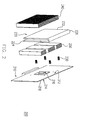
- Fig. 1 is an exploded view of a conventional electronic device.
- the electronic device 100 comprises a circuit board 110, a heat pipe 120, and a heat sink 130.
- the heat pipe 120 and the heat sink 130 are disposed on the circuit board 110, wherein the heat pipe 120 contacts an electronic component 112 on the circuit board 110, and the heat sink 130 is disposed on the heat pipe 120.
- the heat of the electronic component 112 can be conducted to the heat sink 130 through the heat pipe 120, and then conducted to the cool surrounding environment through the heat sink 130.
- one of the objects of the present invention is to provide an electronic device having a heat spreader with good heat dissipation effect.
- the present invention provides an electronic device which comprises a circuit board and a heat spreader.
- the circuit board comprises a first surface, a second surface, and an electronic component, wherein the first surface is opposite to the second surface, and the electronic component is located on the first surface.
- the heat spreader having a first portion, a second portion, and a third portion is disposed on the circuit board. The first portion is located on the first surface of the circuit board, and contacts the electronic component. The second portion is located on the second surface of the circuit board. The third portion is connected between the first portion and the second portion.
- the circuit board further comprises a third surface connected between the first surface and the second surface, and the third portion faces the third surface.
- the heat spreader is U-shaped.
- the electronic device further comprises a first heat sink disposed on the first portion of the heat spreader.
- the electronic device further comprises a second heat sink disposed on the second portion of the heat spreader.
- the electronic device further comprises a plurality of fasteners for fastening the heat spreader on the circuit board.
- the first portion of the heat spreader is in surface contact with the electronic component, so the heat of the electronic component is quickly conducted to the first portion. Moreover, the heat of the electronic component transferred to the first portion can be conducted to the second portion through the third portion, and then transferred to the cool surrounding environment through the second portion. Therefore, the electronic device has a good heat dissipation effect.
- Fig. 1 is an exploded view of a conventional electronic device.
- Fig. 2 is an exploded view of an electronic device having a heat spreader according to an embodiment of the present invention.
- Fig. 3 is a schematic view of the electronic device having a heat spreader being assembled on the motherboard.
- Figs. 4A and 4B are schematic views of the conducting direction of the heat of the electronic component on the heat spreader.
- Fig. 5 is a schematic view of the heat conduction of the heat spreader along line A-A of Fig. 4.
- Fig. 2 is an exploded view of an electronic device having a heat spreader according to an embodiment of the present invention
- Fig. 3 is a schematic view of the electronic device having a heat spreader being assembled on the motherboard.
- the electronic device 200 of the present embodiment is, for example, an interface card such as a display card or a sound card, which is applicable to being plugged in a motherboard 300.
- the electronic device 200 comprises a circuit board 210 and a heat spreader 220.
- the circuit board 210 comprises a first surface 212, a second surface 214, and an electronic component 216, wherein the first surface 212 is opposite to the second surface 214, and the electronic component 216 is located on the first surface 212.
- the heat spreader 220 is disposed on the circuit board 210, and the heat spreader 220 comprises a first portion 222, a second portion 224, and a third portion 226.
- the first portion 222 of the heat spreader 220 is located on the first surface 212 of the circuit board 210, and contacts the electronic component 216.
- the second portion 224 is located on the second surface 214 of the circuit board 210.
- the third portion 226 is connected between the first portion 222 and the second portion 224.
- the circuit board 210 of the present embodiment further comprises a third surface 218, wherein the third surface 218 is connected between the first surface 212 and the second surface 214, and the third portion 226 of the heat spreader 220 faces the third surface 218.
- the heat spreader 220 of the present embodiment is U-shaped, and clamps the circuit board 210.
- the electronic device 200 further comprises a plurality of fasteners 230 for fastening the heat spreader 220 on the circuit board 210.
- the fasteners 230 are screws, but the present invention is not limited to this.
- the electronic device 200 further comprises a first heat sink 240 disposed on the first portion 222 of the heat spreader 220.
- the first heat sink 240 has heat sink fins.
- a second heat sink 250 can be disposed on the second portion 224 of the heat spreader 220.
- the second heat sink 250 also has heat sink fins, so as to enhance the heat dissipation effect of the electronic device 200.
- Figs. 4A and 4B are schematic views of the conducting direction of the heat of the electronic component on the heat spreader
- Fig. 5 is a schematic view of the heat conduction of the heat spreader along line A-A of Fig. 4.
- the electronic component 216 when the electronic component 216 generates heat, the heat of the electronic component 216 is transferred to the first portion 222 of the heat spreader 220, and at this time, the liquid inside the heat spreader 220 is heated to become vapor rising.
- the vapor touches the relatively cool end of the first portion 222, the vapor is condensed to liquid flowing downward along the inner wall of the first portion 222, and the heat released by condensing to the liquid is conducted through one relatively cool end of the first portion 222 to the cooler surrounding environment or to the first heat sink 240.
- the heat of the electronic component 216 (as shown in Fig. 2) is conducted to the first portion 222 of the heat spreader 220 in a surface diffusion manner.
- the heat spreader 220 is attached to the surface of the electronic component 216, thus providing a large heat dissipation area for the electronic component 216 (as shown in Fig. 2), such that the electronic device 200 has an optimal heat dissipation effect.
- the heat spreader 220 of the electronic device 200 has more heat dissipation paths, and thus the electronic component 216 has a better heat dissipation effect than the conventional art.
- the heat spreader of the electronic device of the present invention provides a larger heat dissipation area for the electronic component, so the electronic device has an optimal dissipating effect.
- the heat spreader is U-shaped, so after the heat of the electronic component is conducted to the first portion of the heat spreader, a part of the heat can be transferred to the cool surrounding environment by the heat sink. The remaining heat can be conducted to the second portion through the third portion, and then transferred to the cool surrounding environment through the heat sink.
- the electronic device of the present invention has more heat dissipation paths. Therefore, the electronic device of the present invention has a better heat dissipation effect than the conventional electronic device.
Landscapes
- Cooling Or The Like Of Electrical Apparatus (AREA)
Abstract
An electronic device includes a circuit board and a heat spreader. The circuit board has a first surface, a second surface, and an electronic component. The first surface is opposite to the second surface, and the electronic component is located on the first surface. The heat spreader is disposed on the circuit board has a first portion, a second portion, and a third portion. The first portion is located on the first surface of the circuit board and contacts the electronic component. The second portion is located on the second surface of the circuit board, and the third portion is connected between the first portion and the second portion.
Description
- The present invention relates to an electronic device. More particularly, the present invention relates to an electronic device having a heat spreader with good heat dissipation effect.
- In a computer system, an interface card such as a display card or a sound card serves as the data transmission media between human computer interface (HCI) and computer. In order to satisfy the requirements of users and the increasingly powerful computer functions, the data operation of the interface cards have become more and more complex.
- When the interface cards process a large quantity of operation data, the heat generated by the electronic components such as chips or memories on the interface card increases, such that the interface cards suffering the over high temperature easily influence the performance of the whole system.
- Fig. 1 is an exploded view of a conventional electronic device. Referring to Fig. 1, the
electronic device 100 comprises acircuit board 110, aheat pipe 120, and aheat sink 130. Theheat pipe 120 and theheat sink 130 are disposed on thecircuit board 110, wherein theheat pipe 120 contacts anelectronic component 112 on thecircuit board 110, and theheat sink 130 is disposed on theheat pipe 120. When theelectronic component 112 operates and generates heat, the heat of theelectronic component 112 can be conducted to theheat sink 130 through theheat pipe 120, and then conducted to the cool surrounding environment through theheat sink 130. However, due to the limitation of the shape of theheat pipe 130, when the heat of theelectronic component 112 is transferred to theheat sink 130, the heat dissipation area provided by theheat pipe 120 is small, thus influencing the heat dissipation effect of theelectronic device 100. - Accordingly, one of the objects of the present invention is to provide an electronic device having a heat spreader with good heat dissipation effect.
- In order to achieve the above or other objects, the present invention provides an electronic device which comprises a circuit board and a heat spreader. The circuit board comprises a first surface, a second surface, and an electronic component, wherein the first surface is opposite to the second surface, and the electronic component is located on the first surface. The heat spreader having a first portion, a second portion, and a third portion is disposed on the circuit board. The first portion is located on the first surface of the circuit board, and contacts the electronic component. The second portion is located on the second surface of the circuit board. The third portion is connected between the first portion and the second portion.
- In an embodiment of the present invention, the circuit board further comprises a third surface connected between the first surface and the second surface, and the third portion faces the third surface.
- In an embodiment of the present invention, the heat spreader is U-shaped.
- In an embodiment of the present invention, the electronic device further comprises a first heat sink disposed on the first portion of the heat spreader.
- In an embodiment of the present invention, the electronic device further comprises a second heat sink disposed on the second portion of the heat spreader.
- In an embodiment of the present invention, the electronic device further comprises a plurality of fasteners for fastening the heat spreader on the circuit board.
- In the electronic device of the present invention, the first portion of the heat spreader is in surface contact with the electronic component, so the heat of the electronic component is quickly conducted to the first portion. Moreover, the heat of the electronic component transferred to the first portion can be conducted to the second portion through the third portion, and then transferred to the cool surrounding environment through the second portion. Therefore, the electronic device has a good heat dissipation effect.
- In order to the make aforementioned and other objects, features and advantages of the present invention comprehensible, preferred embodiments accompanied with figures are described in detail below.
- Fig. 1 is an exploded view of a conventional electronic device.
- Fig. 2 is an exploded view of an electronic device having a heat spreader according to an embodiment of the present invention.
- Fig. 3 is a schematic view of the electronic device having a heat spreader being assembled on the motherboard.
- Figs. 4A and 4B are schematic views of the conducting direction of the heat of the electronic component on the heat spreader.
- Fig. 5 is a schematic view of the heat conduction of the heat spreader along line A-A of Fig. 4.
- Fig. 2 is an exploded view of an electronic device having a heat spreader according to an embodiment of the present invention, and Fig. 3 is a schematic view of the electronic device having a heat spreader being assembled on the motherboard. Referring to Fig. 2 and Fig. 3, the
electronic device 200 of the present embodiment is, for example, an interface card such as a display card or a sound card, which is applicable to being plugged in amotherboard 300. Theelectronic device 200 comprises acircuit board 210 and aheat spreader 220. Thecircuit board 210 comprises afirst surface 212, asecond surface 214, and anelectronic component 216, wherein thefirst surface 212 is opposite to thesecond surface 214, and theelectronic component 216 is located on thefirst surface 212. Moreover, theheat spreader 220 is disposed on thecircuit board 210, and theheat spreader 220 comprises afirst portion 222, asecond portion 224, and athird portion 226. Thefirst portion 222 of theheat spreader 220 is located on thefirst surface 212 of thecircuit board 210, and contacts theelectronic component 216. Thesecond portion 224 is located on thesecond surface 214 of thecircuit board 210. Thethird portion 226 is connected between thefirst portion 222 and thesecond portion 224. - Referring to Fig. 2 and Fig. 3, the
circuit board 210 of the present embodiment further comprises athird surface 218, wherein thethird surface 218 is connected between thefirst surface 212 and thesecond surface 214, and thethird portion 226 of theheat spreader 220 faces thethird surface 218. As shown in Fig. 3, theheat spreader 220 of the present embodiment is U-shaped, and clamps thecircuit board 210. Moreover, theelectronic device 200 further comprises a plurality offasteners 230 for fastening theheat spreader 220 on thecircuit board 210. In the present embodiment, thefasteners 230 are screws, but the present invention is not limited to this. - In order to dissipate the heat of the
electronic component 216 more quickly, theelectronic device 200 further comprises afirst heat sink 240 disposed on thefirst portion 222 of theheat spreader 220. In the present embodiment, thefirst heat sink 240 has heat sink fins. Likewise, asecond heat sink 250 can be disposed on thesecond portion 224 of theheat spreader 220. Thesecond heat sink 250 also has heat sink fins, so as to enhance the heat dissipation effect of theelectronic device 200. - Figs. 4A and 4B are schematic views of the conducting direction of the heat of the electronic component on the heat spreader, and Fig. 5 is a schematic view of the heat conduction of the heat spreader along line A-A of Fig. 4. Referring to Fig. 2, Fig. 4A, Fig. 4B, and Fig. 5, when the
electronic component 216 generates heat, the heat of theelectronic component 216 is transferred to thefirst portion 222 of theheat spreader 220, and at this time, the liquid inside theheat spreader 220 is heated to become vapor rising. When the vapor touches the relatively cool end of thefirst portion 222, the vapor is condensed to liquid flowing downward along the inner wall of thefirst portion 222, and the heat released by condensing to the liquid is conducted through one relatively cool end of thefirst portion 222 to the cooler surrounding environment or to thefirst heat sink 240. - It should be noted that due to the
first portion 222 of theheat spreader 220 in surface contact with theelectronic component 216, the heat of the electronic component 216 (as shown in Fig. 2) is conducted to thefirst portion 222 of theheat spreader 220 in a surface diffusion manner. Compared with the conventional art, theheat spreader 220 is attached to the surface of theelectronic component 216, thus providing a large heat dissipation area for the electronic component 216 (as shown in Fig. 2), such that theelectronic device 200 has an optimal heat dissipation effect. - Moreover, after the heat of the
electronic component 216 is conducted to thefirst portion 222 of theheat spreader 220, a part of the heat may be conducted to thefirst heat sink 240, and then transferred to the cool surrounding environment. The heat remained on theheat spreader 220 can be conducted to thesecond portion 224 through thethird portion 226, as shown in Fig. 4B, and then transferred to the cool surrounding environment through thesecond heat sink 250. Therefore, theheat spreader 220 of theelectronic device 200 according to the present embodiment has more heat dissipation paths, and thus theelectronic component 216 has a better heat dissipation effect than the conventional art. - To sum up, the heat spreader of the electronic device of the present invention provides a larger heat dissipation area for the electronic component, so the electronic device has an optimal dissipating effect. In addition, the heat spreader is U-shaped, so after the heat of the electronic component is conducted to the first portion of the heat spreader, a part of the heat can be transferred to the cool surrounding environment by the heat sink. The remaining heat can be conducted to the second portion through the third portion, and then transferred to the cool surrounding environment through the heat sink. Compared with the conventional art, the electronic device of the present invention has more heat dissipation paths. Therefore, the electronic device of the present invention has a better heat dissipation effect than the conventional electronic device.
- It will be apparent to those skilled in the art that various modifications and variations can be made to the structure of the present invention without departing from the scope or spirit of the invention. In view of the foregoing, it is intended that the present invention cover modifications and variations of this invention provided they fall within the scope of the following claims and their equivalents.
Claims (6)
- An electronic device, comprising:a circuit board, having a first surface, a second surface, and an electronic component, wherein the first surface is opposite to the second surface, and the electronic component is located on the first surface; anda heat spreader, disposed on the circuit board, and having a first portion, a second portion, and a third portion, wherein the first portion is located on the first surface of the circuit board and contacts the electronic component, the second portion is located on the second surface, and the third portion is connected between the first portion and the second portion.
- The electronic device as claimed in claim 1, wherein the circuit board further comprises a third surface, the third surface is connected between the first surface and the second surface, and the third portion faces the third surface.
- The electronic device as claimed in claim 1, wherein the heat spreader is U-shaped.
- The electronic device as claimed in claim 1, further comprising a first heat sink disposed on the first portion of the heat spreader.
- The electronic device as claimed in claim 1, further comprising a second heat sink disposed on the second portion of the heat spreader.
- The electronic device as claimed in claim 1, further comprising a plurality of fasteners, for fastening the heat spreader on the circuit board.
Applications Claiming Priority (1)
| Application Number | Priority Date | Filing Date | Title |
|---|---|---|---|
| CNA2006101041199A CN101118458A (en) | 2006-07-31 | 2006-07-31 | Electronic device with temperature equalization plate |
Publications (1)
| Publication Number | Publication Date |
|---|---|
| EP1885170A1 true EP1885170A1 (en) | 2008-02-06 |
Family
ID=38683469
Family Applications (1)
| Application Number | Title | Priority Date | Filing Date |
|---|---|---|---|
| EP07014825A Withdrawn EP1885170A1 (en) | 2006-07-31 | 2007-07-27 | Electronic device having heat spreader |
Country Status (3)
| Country | Link |
|---|---|
| US (1) | US20080024993A1 (en) |
| EP (1) | EP1885170A1 (en) |
| CN (1) | CN101118458A (en) |
Cited By (1)
| Publication number | Priority date | Publication date | Assignee | Title |
|---|---|---|---|---|
| WO2014169814A1 (en) | 2013-04-15 | 2014-10-23 | Shenzhen Byd Auto R&D Company Limited | Wireless charging device and method using the same |
Families Citing this family (4)
| Publication number | Priority date | Publication date | Assignee | Title |
|---|---|---|---|---|
| US9609739B2 (en) * | 2015-03-10 | 2017-03-28 | Kabushiki Kaisha Toshiba | Electronic device |
| CN112443551A (en) * | 2019-09-05 | 2021-03-05 | 英业达科技有限公司 | Screw and interface card |
| US11657408B2 (en) | 2020-01-07 | 2023-05-23 | Bank Of America Corporation | Synchronously tracking and controlling events across multiple computer systems |
| TWI761285B (en) * | 2021-09-06 | 2022-04-11 | 華碩電腦股份有限公司 | Interface card assembly and circuit board module using the same |
Citations (3)
| Publication number | Priority date | Publication date | Assignee | Title |
|---|---|---|---|---|
| US6326686B1 (en) * | 1997-09-09 | 2001-12-04 | Samsung Electronics Co., Ltd. | Vertical semiconductor device package having printed circuit board and heat spreader, and module having the packages |
| US6449159B1 (en) * | 2000-05-03 | 2002-09-10 | Rambus Inc. | Semiconductor module with imbedded heat spreader |
| US20060104035A1 (en) * | 2004-08-24 | 2006-05-18 | Vasoya Kalu K | Edge plated printed wiring boards |
Family Cites Families (11)
| Publication number | Priority date | Publication date | Assignee | Title |
|---|---|---|---|---|
| US5396403A (en) * | 1993-07-06 | 1995-03-07 | Hewlett-Packard Company | Heat sink assembly with thermally-conductive plate for a plurality of integrated circuits on a substrate |
| US6180436B1 (en) * | 1998-05-04 | 2001-01-30 | Delco Electronics Corporation | Method for removing heat from a flip chip semiconductor device |
| JP3109479B2 (en) * | 1998-06-12 | 2000-11-13 | 日本電気株式会社 | Heat radiator and memory module equipped with heat radiator |
| US6421240B1 (en) * | 2001-04-30 | 2002-07-16 | Hewlett-Packard Company | Cooling arrangement for high performance electronic components |
| US6535387B2 (en) * | 2001-06-28 | 2003-03-18 | Intel Corporation | Heat transfer apparatus |
| US6882536B2 (en) * | 2002-04-25 | 2005-04-19 | Hewlett-Packard Development Company, L.P. | Wrap-around cooling arrangement for printed circuit board |
| US6821816B1 (en) * | 2003-06-13 | 2004-11-23 | Delphi Technologies, Inc. | Relaxed tolerance flip chip assembly |
| US7019974B2 (en) * | 2004-07-16 | 2006-03-28 | Hon Hai Precision Industry Co., Ltd. | Heat dissipation device |
| US7106595B2 (en) * | 2004-09-15 | 2006-09-12 | International Business Machines Corporation | Apparatus including a thermal bus on a circuit board for cooling components on a daughter card releasably attached to the circuit board |
| USD531965S1 (en) * | 2004-10-28 | 2006-11-14 | Mushkin, Inc. | Memory card heat sink |
| US7319588B2 (en) * | 2006-01-25 | 2008-01-15 | Fu Zhun Precision Industry (Shen Zhen) Co., Ltd. | Heat dissipation device |
-
2006
- 2006-07-31 CN CNA2006101041199A patent/CN101118458A/en active Pending
-
2007
- 2007-07-26 US US11/829,064 patent/US20080024993A1/en not_active Abandoned
- 2007-07-27 EP EP07014825A patent/EP1885170A1/en not_active Withdrawn
Patent Citations (3)
| Publication number | Priority date | Publication date | Assignee | Title |
|---|---|---|---|---|
| US6326686B1 (en) * | 1997-09-09 | 2001-12-04 | Samsung Electronics Co., Ltd. | Vertical semiconductor device package having printed circuit board and heat spreader, and module having the packages |
| US6449159B1 (en) * | 2000-05-03 | 2002-09-10 | Rambus Inc. | Semiconductor module with imbedded heat spreader |
| US20060104035A1 (en) * | 2004-08-24 | 2006-05-18 | Vasoya Kalu K | Edge plated printed wiring boards |
Cited By (3)
| Publication number | Priority date | Publication date | Assignee | Title |
|---|---|---|---|---|
| WO2014169814A1 (en) | 2013-04-15 | 2014-10-23 | Shenzhen Byd Auto R&D Company Limited | Wireless charging device and method using the same |
| EP2944074A4 (en) * | 2013-04-15 | 2016-04-06 | Byd Co Ltd | WIRELESS CHARGING DEVICE AND METHOD USING THE SAME |
| US9667075B2 (en) | 2013-04-15 | 2017-05-30 | Byd Company Limited | Wireless charging device and method using the same |
Also Published As
| Publication number | Publication date |
|---|---|
| CN101118458A (en) | 2008-02-06 |
| US20080024993A1 (en) | 2008-01-31 |
Similar Documents
| Publication | Publication Date | Title |
|---|---|---|
| US7640968B2 (en) | Heat dissipation device with a heat pipe | |
| US7019974B2 (en) | Heat dissipation device | |
| US7272001B2 (en) | External conductive heat dissipating device for microcomputers | |
| US7369412B2 (en) | Heat dissipation device | |
| CN101506755A (en) | Methods and systems for cooling a computing device | |
| US20040223302A1 (en) | Apparatus for cooling heat generating components within a computer system enclosure | |
| US8861195B2 (en) | Computer with heat dissipation system | |
| US20080007914A1 (en) | Heat dissipation device | |
| CN101072482A (en) | Radiating device and radiating system using same | |
| US8724323B2 (en) | Electronic device with heat dissipation apparatus | |
| US7929302B2 (en) | Cooling device | |
| US20080024993A1 (en) | Electronic device having heat spreader | |
| US7321491B2 (en) | Heat sink for a portable computer | |
| US8743547B2 (en) | Electronic device having cooling structure | |
| US20090180254A1 (en) | Electronic assembly and heat sink | |
| US20090080161A1 (en) | Heat dissipation device for computer add-on card | |
| US20080078528A1 (en) | Heat sink with heat pipes | |
| US20080218964A1 (en) | Desktop personal computer and thermal module thereof | |
| US20080137287A1 (en) | Thermally integrated electronic enclosures | |
| US7729120B2 (en) | Heat sink apparatus | |
| TW201144987A (en) | Heat sink and electronic device | |
| CN2485794Y (en) | Scalable heat conduction device | |
| CN102279638A (en) | Radiator and electronic device using same | |
| CN101571741B (en) | Heat dissipation module and electronic device with the heat dissipation module | |
| KR100313310B1 (en) | Portable computer with the dissipating apparatus of electronic system |
Legal Events
| Date | Code | Title | Description |
|---|---|---|---|
| PUAI | Public reference made under article 153(3) epc to a published international application that has entered the european phase |
Free format text: ORIGINAL CODE: 0009012 |
|
| AK | Designated contracting states |
Kind code of ref document: A1 Designated state(s): AT BE BG CH CY CZ DE DK EE ES FI FR GB GR HU IE IS IT LI LT LU LV MC MT NL PL PT RO SE SI SK TR |
|
| AX | Request for extension of the european patent |
Extension state: AL BA HR MK YU |
|
| 17P | Request for examination filed |
Effective date: 20080806 |
|
| AKX | Designation fees paid |
Designated state(s): DE FR GB |
|
| STAA | Information on the status of an ep patent application or granted ep patent |
Free format text: STATUS: THE APPLICATION HAS BEEN WITHDRAWN |
|
| 18W | Application withdrawn |
Effective date: 20090701 |