EP1885118A2 - Hinge apparatus and image displaying apparatus - Google Patents
Hinge apparatus and image displaying apparatus Download PDFInfo
- Publication number
- EP1885118A2 EP1885118A2 EP07014536A EP07014536A EP1885118A2 EP 1885118 A2 EP1885118 A2 EP 1885118A2 EP 07014536 A EP07014536 A EP 07014536A EP 07014536 A EP07014536 A EP 07014536A EP 1885118 A2 EP1885118 A2 EP 1885118A2
- Authority
- EP
- European Patent Office
- Prior art keywords
- rotation
- rotation axis
- hole
- base
- side portion
- Prior art date
- Legal status (The legal status is an assumption and is not a legal conclusion. Google has not performed a legal analysis and makes no representation as to the accuracy of the status listed.)
- Granted
Links
- 230000001105 regulatory effect Effects 0.000 claims description 24
- 230000007246 mechanism Effects 0.000 description 15
- 239000000463 material Substances 0.000 description 12
- 238000005452 bending Methods 0.000 description 9
- 239000002184 metal Substances 0.000 description 8
- 229910052751 metal Inorganic materials 0.000 description 8
- 238000000034 method Methods 0.000 description 5
- 238000010276 construction Methods 0.000 description 4
- 230000005489 elastic deformation Effects 0.000 description 4
- 230000001747 exhibiting effect Effects 0.000 description 4
- 230000008569 process Effects 0.000 description 4
- 238000006243 chemical reaction Methods 0.000 description 3
- 238000004891 communication Methods 0.000 description 3
- 230000000052 comparative effect Effects 0.000 description 3
- 238000003384 imaging method Methods 0.000 description 3
- 150000002739 metals Chemical class 0.000 description 3
- 230000004048 modification Effects 0.000 description 3
- 238000012986 modification Methods 0.000 description 3
- 230000003287 optical effect Effects 0.000 description 3
- 229920001707 polybutylene terephthalate Polymers 0.000 description 3
- 238000003825 pressing Methods 0.000 description 3
- 238000012545 processing Methods 0.000 description 3
- 230000006835 compression Effects 0.000 description 2
- 238000007906 compression Methods 0.000 description 2
- 230000002349 favourable effect Effects 0.000 description 2
- 239000004973 liquid crystal related substance Substances 0.000 description 2
- 230000002093 peripheral effect Effects 0.000 description 2
- 229920006324 polyoxymethylene Polymers 0.000 description 2
- 229920005989 resin Polymers 0.000 description 2
- 239000011347 resin Substances 0.000 description 2
- 229920003002 synthetic resin Polymers 0.000 description 2
- 239000000057 synthetic resin Substances 0.000 description 2
- 229910000906 Bronze Inorganic materials 0.000 description 1
- OAICVXFJPJFONN-UHFFFAOYSA-N Phosphorus Chemical compound [P] OAICVXFJPJFONN-UHFFFAOYSA-N 0.000 description 1
- 229930182556 Polyacetal Natural products 0.000 description 1
- 230000009471 action Effects 0.000 description 1
- 230000004323 axial length Effects 0.000 description 1
- 239000010974 bronze Substances 0.000 description 1
- 230000008859 change Effects 0.000 description 1
- KUNSUQLRTQLHQQ-UHFFFAOYSA-N copper tin Chemical compound [Cu].[Sn] KUNSUQLRTQLHQQ-UHFFFAOYSA-N 0.000 description 1
- 230000008878 coupling Effects 0.000 description 1
- 238000010168 coupling process Methods 0.000 description 1
- 238000005859 coupling reaction Methods 0.000 description 1
- 230000003247 decreasing effect Effects 0.000 description 1
- 230000006870 function Effects 0.000 description 1
- 239000003365 glass fiber Substances 0.000 description 1
- 239000004519 grease Substances 0.000 description 1
- 230000002452 interceptive effect Effects 0.000 description 1
- 239000000314 lubricant Substances 0.000 description 1
- 230000013011 mating Effects 0.000 description 1
- 239000007769 metal material Substances 0.000 description 1
- -1 polybutylene terephthalate Polymers 0.000 description 1
- 238000004080 punching Methods 0.000 description 1
- 238000001454 recorded image Methods 0.000 description 1
- 238000012360 testing method Methods 0.000 description 1
Images





Classifications
-
- H—ELECTRICITY
- H04—ELECTRIC COMMUNICATION TECHNIQUE
- H04N—PICTORIAL COMMUNICATION, e.g. TELEVISION
- H04N23/00—Cameras or camera modules comprising electronic image sensors; Control thereof
- H04N23/50—Constructional details
- H04N23/53—Constructional details of electronic viewfinders, e.g. rotatable or detachable
- H04N23/531—Constructional details of electronic viewfinders, e.g. rotatable or detachable being rotatable or detachable
-
- H—ELECTRICITY
- H04—ELECTRIC COMMUNICATION TECHNIQUE
- H04N—PICTORIAL COMMUNICATION, e.g. TELEVISION
- H04N23/00—Cameras or camera modules comprising electronic image sensors; Control thereof
-
- E—FIXED CONSTRUCTIONS
- E05—LOCKS; KEYS; WINDOW OR DOOR FITTINGS; SAFES
- E05D—HINGES OR SUSPENSION DEVICES FOR DOORS, WINDOWS OR WINGS
- E05D11/00—Additional features or accessories of hinges
- E05D11/10—Devices for preventing movement between relatively-movable hinge parts
- E05D11/1028—Devices for preventing movement between relatively-movable hinge parts for maintaining the hinge in two or more positions, e.g. intermediate or fully open
- E05D11/1078—Devices for preventing movement between relatively-movable hinge parts for maintaining the hinge in two or more positions, e.g. intermediate or fully open the maintaining means acting parallel to the pivot
-
- E—FIXED CONSTRUCTIONS
- E05—LOCKS; KEYS; WINDOW OR DOOR FITTINGS; SAFES
- E05D—HINGES OR SUSPENSION DEVICES FOR DOORS, WINDOWS OR WINGS
- E05D3/00—Hinges with pins
- E05D3/06—Hinges with pins with two or more pins
- E05D3/10—Hinges with pins with two or more pins with non-parallel pins
-
- E—FIXED CONSTRUCTIONS
- E05—LOCKS; KEYS; WINDOW OR DOOR FITTINGS; SAFES
- E05Y—INDEXING SCHEME ASSOCIATED WITH SUBCLASSES E05D AND E05F, RELATING TO CONSTRUCTION ELEMENTS, ELECTRIC CONTROL, POWER SUPPLY, POWER SIGNAL OR TRANSMISSION, USER INTERFACES, MOUNTING OR COUPLING, DETAILS, ACCESSORIES, AUXILIARY OPERATIONS NOT OTHERWISE PROVIDED FOR, APPLICATION THEREOF
- E05Y2999/00—Subject-matter not otherwise provided for in this subclass
-
- Y—GENERAL TAGGING OF NEW TECHNOLOGICAL DEVELOPMENTS; GENERAL TAGGING OF CROSS-SECTIONAL TECHNOLOGIES SPANNING OVER SEVERAL SECTIONS OF THE IPC; TECHNICAL SUBJECTS COVERED BY FORMER USPC CROSS-REFERENCE ART COLLECTIONS [XRACs] AND DIGESTS
- Y10—TECHNICAL SUBJECTS COVERED BY FORMER USPC
- Y10S—TECHNICAL SUBJECTS COVERED BY FORMER USPC CROSS-REFERENCE ART COLLECTIONS [XRACs] AND DIGESTS
- Y10S248/00—Supports
- Y10S248/917—Video display screen support
- Y10S248/919—Adjustably orientable video screen support
- Y10S248/922—Angular
- Y10S248/923—Tilting
Definitions
- FIG. 2A shows a first rotation position in which the image displaying panel 152 is turned approximately 90° (refer to an arrow A) about X-axis orthogonal to a face including an optical axis CL from the basic position (hereinafter, the X-axis is also referred to as a first rotation axis) .
- FIG. 1A shows a first rotation position in which the image displaying panel 152 is turned approximately 90° (refer to an arrow A) about X-axis orthogonal to a face including an optical axis CL from the basic position (hereinafter, the X-axis is also referred to as a first rotation axis) .
- a third stud 9 is rotatably supported about the Y-axis coaxial with the axis of the third stud 9.
- the third stud 9 is fixed to a sub frame 3.
- the base frame 2 can be rotated in a range of a predetermined angle about the X-axis, with respect to the first and second brackets 1A and 1B.
- the base frame 2, in the rotation of the base frame 2, includes a cam mechanism M1 exhibiting a predetermined frictional force and providing a click feel at a specified angle.
- a through hole 2b1 substantially at the central portion of the longer side portion 2b.
- the central axis of the through hole 2b1 is the Y-axis in the hinge apparatus 50.
- a pair of square holes 2b2 and 2b2 spaced apart from each other in the X-axis direction is formed.
- a protruding portion 2b3 is formed by half-punching so as to be adjacent to the one square hole 2b2 to protrude inward in a rectangular shape.
- each member is set to be of a length in the X-axis direction such that the coil spring 12 is compressed a predetermined amount in a longitudinal direction of the coil spring 12.
- the coil spring 12 biases the cam shaft 5 in a direction in which the cam portion 5M presses the cam portion 6M.
- FIG. 12 is a view of the hinge apparatus 50 taken in a direction orthogonal to the X-axis and the Y-axis .
- the L-shaped uprising portion 2a2 and the uprising portion 2a3 provided at the base frame 2 are formed along the side face of the cam shaft 5.
- the cam shaft 5 is held such that the looseness in a direction orthogonal to the X-axis is of a minimal amount, between the L-shaped uprising portion 2a2 and the longer side portion 2b and between the uprising portion 2a3 and the longer side portion 2b, so that this engagement structure prevents the cam shaft 5 from being released from on the X-axis.
- both the first and the second brackets 1A and 1B side and the main frame 2 side that are contacted with each other are constructed to be of the above-described configuration, a high strength can be obtained to be favorable.
- either one of the first and second brackets 1A and 1B side and the main frame 2 side may be of the above-described configuration or construction. Even in this case, a high rotation-regulating strength can be obtained.
- a lubricant such as grease may be applied to a sliding portion of each member.
Landscapes
- Engineering & Computer Science (AREA)
- Multimedia (AREA)
- Signal Processing (AREA)
- Pivots And Pivotal Connections (AREA)
- Devices For Indicating Variable Information By Combining Individual Elements (AREA)
Abstract
Description
- The present invention relates to a hinge apparatus and an image displaying apparatus, and more specifically to a hinge apparatus and an image displaying apparatus provided with a hinge structure for opening and closing an image displaying panel displaying an image.
- An image displaying apparatus provided with a thin image displaying panel such as a liquid crystal display element is conventionally known. Specifically, as the image displaying apparatus, a video camera, a digital still camera, a mobile phone, a notebook computer, a portable DVD (Digital Versatile Disc) player or the like is known.
- The image displaying apparatus is provided with an apparatus main body and an image displaying panel. Furthermore, some of these image displaying apparatuses each includes a hinge apparatus employed to couple the image displaying panel with the apparatus main body such that the image displaying panel can be opened or closed with respect to the apparatus main body. Normally, the hinge apparatus is constructed so as to keep a closed state in which the image displaying panel is in a close contact with the apparatus main body when the image displaying apparatus is not used, as well as so as to keep an opened state in which the image displaying panel stands about at 90° with respect to the apparatus main body when the image displaying apparatus is used.
- In the case where the image displaying apparatus is a notebook computer or a portable DVD player, a hinge apparatus can be turned about one axis between the closed state and the opened state. In contrast, in the case where the image displaying apparatus is a video camera, a digital still camera or a mobile phone, the hinge apparatus can be turned about one axis between the closed state and the opened state, as well as can be turned about the other axis in the opened state. That is, the hinge apparatus is constructed such that the image displaying panel can be turned about a first axis and a second axis which intersect at right angles with each other.
- In
Japanese Patent Application Laid-Open No. 2001-272719 - In
Japanese Patent Application Laid-Open No. 2000-240636 Japanese Patent Application Laid-Open No. 2001-272719 - In the image displaying apparatus, the first rotation axis in each of these hinge apparatuses is normally set to be a rotation axis for opening or closing an image displaying panel. Therefore, in respect of turning about the first rotation axis, the image displaying panel is required to be held in an arbitrary angular position. Furthermore, in respect of turning about the first rotation axis, it is required that a user can feel an appropriate and comfortable frictional feel and obtain a click feel at a specified angular position.
- A hinge mechanism to meet the above-described requirements is disclosed in
Japanese Patent Application Laid-Open No. H10 (1998)-311327 - Meanwhile, an image displaying apparatus onto which the hinge apparatus as described above is mounted increasingly comes to be downsized and weight-saved accompanied with the enlargement of spread of mobile applications.
- As the image displaying apparatus is downsized, the hinge apparatus is downsized and a plurality of members employed in the hinge apparatus are made thin for weight saving, which results in the tendency of decreased strength or rigidity. Normally, a predetermined rotation angle range in which an image displaying panel can be turned is set to the image displaying apparatus. Thus, in order to inhibit the image displaying panel from being turned over the predetermined rotation angle range, a stopper structure is provided at the hinge apparatus. However, due to thinning of the members employed in the hinge apparatus, the strength of the stopper structure tends to decrease.
- Furthermore, even if the members employed in the hinge apparatus are made thin, turning force to be applied to the image displaying panel by a user (force provided by hands) in order to position the image displaying panel in a desired posture, is not changed. Thus, when the image displaying panel is turned, force larger than the force to which the thinned stopper structure can be resistant is applied, which results in a higher possibility that the hinge apparatus is damaged.
- In particular, in respect of turning about the first rotation axis, that is, opening or closing the image displaying panel, the image displaying panel is likely to bump on a wall or a desk in a state in which the image displaying panel is opened. When the image displaying panel is bumped on the wall or the desk, unintended force is forcibly applied to the stopper structure, which results in a high possibility that the hinge apparatus is damaged. Thus, even if the hinge apparatus is downsized, rotation-regulating strength of the stopper structure provided at the hinge apparatus is desired to keep high.
- As described in
Japanese Patent Application Laid-Open No. 2000-240636 - In this rotation-regulating structure, the bracket is merely bent to form the angle-regulating piece. Thus, when strong force is applied to the angle-regulating piece, the angle-regulating piece is deformed to make it impossible to conduct a rotation regulation at a predetermined position and there is a possibility that a hinge apparatus is damaged.
- The hinge apparatus described in
Japanese Patent Application Laid-Open No. 2001-272719 - The hinge apparatus described in
Japanese Patent Application Laid-Open No. 2000-240636 - In a hinge mechanism described in
Japanese Patent Application Laid-Open No. H10(1998)-311327 - A first object of the present invention is to provide a hinge apparatus having extremely high rotation-regulating strength of a stopper regulating a rotation angle.
- A second object of the present invention is to provide an image displaying apparatus having extremely high rotation-regulating strength of a stopper regulating a rotation angle when an image displaying panel is opened and closed with respect to a main body portion (apparatus main body).
- A third object of the present invention is to provide a hinge apparatus capable of being downsized in which a rotation member can be held with stability at an arbitrary angular position, a frictional touch of high quality can be obtained in rotation operation, and a click feel of high quality can be obtained at a specified angular position in the rotation operation.
- A fourth object of the present invention is to provide an image displaying apparatus capable of being downsized in which an image displaying panel can be held with stability at an arbitrary angular position, a frictional touch of high quality can be obtained in rotation operation, and a click feel of high quality can be obtained at a specified angular position in the rotation operation.
- To achieve the above-described objects, the applied present invention first provides the following (A) to (K):
- (A) A hinge apparatus (50) comprising: a rotation body (50B); and a fixed body (50A) configured to support the rotation body (50B) rotatably about a rotation axis (X), wherein the rotation body (50B) includes: a base frame (2) having: a base body portion (2b) extending along the rotation axis (X); and a side portion (2cA) extending from an end of the base body portion (2b) in a direction orthogonal to the rotation axis (X) and formed with a first through hole (2c1) with the rotation axis (X) as a central axis, wherein the fixed body (50A) includes: a bracket (1A) having: a base portion (1Aa); a first side portion (1Ab) extending from a first edge of the base portion (1Aa); a second side portion (1Ac) extending from a second edge of the base portion (1Aa) ; a superimposed portion (1Ad) extending from the second side portion (1Ac) so as to be overlapped with the first side portion (1Ab); a second through hole (1Ae) passing through the first side portion (1Ab); and a third through hole (1Af) passing through the superimposed portion (1Ad) and communicating with the second through hole (1Ae); and a stud (7) inserted through the first through hole (2c1), the second through hole (1Ae) and the third through hole (1Af), and secured to the bracket (1A) so as to rotatably support the base frame (2) with respect to the bracket (1A), and wherein the base frame (2) has a contact portion (2a6) to be in contact with at least one of the first side portion (1Ab), the superimposed portion (1Ad) and the stud (7) in a predetermined angular position with respect to the bracket (1A), and by the contact, the rotation body (50B) is regulated from rotating with respect to the fixed body (50A);
- (B) A hinge apparatus (50) comprising: a rotation body (50B); and a fixed body (50A) configured to support the rotation body (50B) rotatably about a rotation axis (X), wherein the rotation body (50B) includes a base frame (2) having: a base body portion (2b) extending along the rotation axis (X) ; a side portion (2cA) extending from an end of the base body portion (2b) in a direction orthogonal to the rotation axis (X) and having a first through hole (2c1) with the rotation axis (X) as a central axis and a cut portion (2c2) formed by cutting an outer edge of the side portion (2cA); and a longer side portion (2a) having an extending portion (2a6) and extending from an end of the base body portion (2b) outwardly of the base body portion (2b) along the rotation axis (X), the extending portion (2a6) is engaged with the cut portion (2c2) and has a protruding portion (2a6t) protruding outward beyond an outer surface of the side portion (2c) on a tip end side of the extending portion (2a6), wherein the fixed body (50A) includes: a bracket (1A) having a second through hole (1Ae) ; and a stud (7) inserted through the first through hole (2c1) and the second through hole (1Ae) and secured to the bracket (1A) so as to rotatably support the base frame (2) with respect to the bracket (1A), and wherein the protruding portion (2a6t) of the base frame (2) is in contact with at least one of the bracket (1A) and the stud (7) in a predetermined angular position with respect to the bracket (1A), and thereby the rotation body (50B) is regulated from rotating with respect to the fixed body (50A);
- (C) A hinge apparatus (50) comprising :a rotation body (50B); and a fixed body (50A) configured to support the rotation body (50B) rotatably about a rotation axis (X), wherein the rotation body (50B) includes a base frame (2) having: a base body portion (2b) extending along the rotation axis (X); a side portion (2c) extending from an end of the base body portion (2b) in a direction orthogonal to the rotation axis (X) and having a first through hole (2c1) with the rotation axis (X) as a central axis and a cut portion (2c2) formed by cutting an outer edge of the side portion (2c); and a longer side portion (2a) having an extending portion (2a6) and extending from an end of the base body portion (2b) outwardly of the base body portion (2b) along the rotation axis (X), the extending portion (2a6) is engaged with the cut portion (2c2) and has a protruding portion (2a6t) protruding outward beyond an outer surface of the side portion (2c) on a tip end side of the extending portion (2a6), wherein the fixed body (50A) includes: a bracket (1A) having: a base portion (1Aa); a first side portion (1Ab) extending from a first edge of the base portion (1Aa) ; a second side portion (1Ac) extending from a second edge of the base portion (1Aa); a superimposed portion (1Ad) extending from the second side portion (1Ac) so as to be overlapped with the first side portion (1Ab); a second through hole (1Ae) passing through the first side portion (1Ab); and a third through hole (1Af) passing through the superimposed portion (1Ad) and communicating with the second through hole (1Ae) ; and a stud (7) inserted through the first through hole (2c1), the second through hole (1Ae) and the third through hole (1Af), and secured to the bracket (1A) so as to rotatably support the base frame (2) with respect to the bracket (1A), and wherein the protruding portion (2a6t) of the base frame (2) is in contact with at least one of the first side portion (1Ab), the superimposed portion (1Ad) and the stud (7) in a predetermined angular position with respect to the bracket (1A), and thereby the rotation body (50B) is regulated from rotating with respect to the fixed body (50A);
- (D) An image displaying apparatus (150) comprising: a main body portion (151); an image displaying portion (152) configured to display an image; and a hinge apparatus (50) configured to cause the image displaying portion (152) to turn about at least one axis with respect to the main body portion (151), wherein the hinge apparatus (50) comprises: a rotation body (50B); and a fixed body (50A) configured to support the rotation body (50B) rotatably about a rotation axis (X), the rotation body (50B) including: a base frame (2) having a base body portion (2b) extending along the rotation axis (X); and a side portion (2cA) extending from an end of the base body portion (2b) in a direction orthogonal to the rotation axis (X) and formed with a first through hole (2c1) with the rotation axis (X) as a central axis, and the fixed body (50A) including: a bracket (1A) having: a base portion (1Aa); a first side portion (1Ab) extending from a first edge of the base portion (1A); a second side portion (1Ac) extending from a second edge of the base portion (1Aa); a superimposed portion (1Ad) extending from the second side portion (1Ac) so as to be overlapped with the first side portion (1Ab); a second through hole (1Ae) passing through the first side portion (1Ab); and a third through hole (1Af) passing through the superimposed portion (1Ad) and communicating with the second through hole (1Ae); and a stud (7) inserted through the first through hole (2c1), the second through hole (1Ae) and the third through hole (1Af), and secured to the bracket (1A) so as to rotatably support the base frame (2) with respect to the bracket (1A), and wherein the base frame (2) includes a contact portion (2a6) to be in contact with at least one of the first side portion (1Ab), the superimposed portion (1Ad) and the stud (7) in a predetermined angular position with respect to the bracket (1A), by the contact, the rotation body (50B) is regulated from rotating with respect to the fixed body (50A), the fixed body (50A) is coupled to the main body portion (151), and the rotation body (50B) is coupled to the image displaying portion (152);
- (E) An image displaying apparatus (150) comprising: a main body portion (151); an image displaying portion (152) configured to display an image; and a hinge apparatus (50) configured to cause the image displaying portion (152) to turn about at least one axis with respect to the main body portion (151), wherein the hinge apparatus (50) comprises: a rotation body (50B); and a fixed body (50A) configured to support the rotation body (50B) rotatably about a rotation axis (X) ; the rotation body (50B) including a base frame (2) having: a base body portion (2b) extending along the rotation axis (X) ; a side portion (2cA) extending from an end of the base body portion (2b) in a direction orthogonal to the rotation axis (X) and having: a first through hole (2c1) with the rotation axis (X) as a central axis; and a cut portion (2c2) formed by cutting an outer edge of the side portion (2cA); and a longer side portion (2a) having an extending portion (2a6) and extending from an end of the base body portion (2b) outwardly of the base body portion (2b) along the rotation axis (X), the extending portion (2a6) is engaged with the cut portion (2c2) and has a protruding portion (2a6t) protruding outward beyond the outer surface of the side portion (2c) on a tip end side of the extending portion (2a6), and the fixed body (50A) including: a bracket (1A) having a second through hole (1Ae); and a stud (7) inserted through the first through hole (2c1) and the second through hole (1Ae) and secured to the bracket (1A) so as to rotatably support the base frame (2) with respect to the bracket (1A), and wherein the protruding portion (2a6t) of the base frame (2) is in contact with at least one of the bracket (1A) and the stud (7) in a predetermined angular position with respect to the bracket (1A), and thereby the rotation body (50B) is regulated from rotating with respect to the fixed body (50A), the fixed body (50A) is coupled to the main body portion (151), and the rotation body (50B) is coupled to the image displaying portion (152);
- (F) An image displaying apparatus (150) comprising: a main body portion (151); an image displaying portion (152) configured to display an image; and a hinge apparatus (50) configured to cause the image displaying portion (152) to turn about at least one axis with respect to the main body portion (151), wherein the hinge apparatus (50) comprises: a rotation body (50B); and a fixed body (50A) configured to support the rotation body (50B) rotatably about a rotation axis (X), the rotation body (50B) including a base frame (2) having: a base body portion (2b) extending along the rotation axis (X); a side portion (2c) extending from an end of the base body portion (2b) in a direction orthogonal to the rotation axis (X) and having: a first through hole (2c1) with the rotation axis (X) as a central axis; and a cut portion (2c2) formed by cutting an outer edge of the side portion (2c); and a longer side portion (2a) having an extending portion (2a6) and extending from an end of the base body portion (2b) outwardly of the base body portion (2b) along the rotation axis (X), the extending portion (2a6) is engaged with the cut portion (2c2) and has a protruding portion (2a6t) protruding outward beyond the outer surface of the side portion (2c) on a tip end side of the extending portion (2a6), and the fixed body (50A) including: a bracket (1A) having: a base portion (1Aa); a first side portion (1Ab) extending from a first edge of the base portion (1Aa); a second side portion (1Ac) extending from a second edge of the base portion (1Aa); a superimposed portion (1Ad) extending from the second side portion (1Ac) so as to be overlapped with the first side portion (1Ab); a second through hole (1Ae) passing through the first side portion (1Ab); and a third through hole (1Af) passing through the superimposed portion (1Ad) and communicating with the second through hole (1Ae); and a stud (7) inserted through the first through hole (2c1), the second through hole (1Ae) and the third through hole (1Af) and secured to the bracket (1A) so as to rotatably support the base frame (2) with respect to the bracket (1A), and wherein the protruding portion (2a6t) of the base frame (2) is in contact with at least one of the first side portion (1Ab), the superimposed portion (1Ad) and the stud (7) in a predetermined angular position with respect to the bracket (1A), and thereby the rotation body (50B) is regulated from rotating with respect to the fixed body (50A) ; the fixed body (50A) is coupled to the main body portion (151); and the rotation body (50B) is coupled to the image displaying portion (152);
- (G) A hinge apparatus (50) comprising: a rotation body (50B); and a fixed body (50A) configured to support the rotation body (50B) rotatably about one rotation axis (X), wherein the rotation body (50B) includes: a base frame (2) having: a base body portion (2b) extending along the one rotation axis (X) ; a first side portion (2cA) extending from a first end of the base body portion (2b) in a direction orthogonal to the one rotation axis (X) and formed with a first through hole (2c1) with the one rotation axis (X) as a central axis; and a second side portion (2cB) extending from a second end of the base body portion (2b) in a direction orthogonal to the one rotation axis (X) and formed with a second through hole (2c1) with the one rotation axis (X) as a center axis; a first cam body (5) formed with a first cam face (5M) at one end thereof, suppresses by the base body portion (2b) the rotation about the one rotation axis (X) with respect to the base body portion (2b), and supported by the base body portion (2b) so as to be movable in a direction of the one rotation axis (X) ; and a biasing body (12) disposed between the first cam body (5) and the second side portion (2cB) and biasing the first cam body (5) toward the first side portion (2cA), wherein the fixed body (50A) includes: a first shaft (7) inserted in the first through hole (2c1) of the first side portion (2cA) and supporting the base frame (2) rotatably about the one rotation axis (X); a second shaft (8) inserted in the second through hole (2c1) of the second side portion (2CB) and supporting the base frame (2) rotatably about the one rotation axis (X); and a second cam body (6) formed with a second cam face (6M) at one end thereof and supported by the first shaft (7) between the first cam body (5) and the first side portion (2cA) so that the rotation about the one rotation axis (X) with respect to the first shaft (7) is suppressed, and wherein the first cam face (5M) and the second cam face (6M) are pressed and contacted with each other by a bias of the biasing body (12);
- (H) The hinge apparatus according to (G), wherein a distance (Ls) between tip ends of the first shaft (7) and the second shaft (8) is longer than that of the first cam body (5) in a direction of the one rotation axis (X);
- (I) The hinge apparatus according to (G), wherein the base body portion (2b) of the base frame (2) includes: a third through hole (2b1) with the other rotation axis (Y) orthogonal to a plane containing the one rotation axis (X) as a central axis; a third shaft (9) inserted from the outside in the third through hole (2b1); a shaft fixing portion (11) fixed to a tip end of the third shaft (9) having been inserted, sandwiching the base body portion (2b) between the shaft fixing portion (11) and the third shaft (9), and rotating about the other rotation axis (Y) with respect to the base frame (2); and a concave portion (5g) provided at the side portion of the first cam body (5), and wherein the shaft fixing portion (11) comes in the concave portion (5g).
- (J) An image displaying apparatus (150) comprising: a main body portion (151); an image displaying portion (152) configured to display an image; and a hinge apparatus (50) configured to cause the image displaying portion (152) to turn about at least one axis with respect to the main body portion (151), wherein the hinge apparatus (50) comprises: a rotation body (50B); and a fixed body (50A) configured to support the rotation body (50B) rotatably about one rotation axis (X), the rotation body (50B) including: a base frame (2) having: a base body portion (2b) extending along the one rotation axis (X) ; a first side portion (2cA) extending from a first end of the base body portion (2b) in a direction orthogonal to the one rotation axis (X) and formed with a first through hole (2c1) with the one rotation axis (X) as a central axis; and a second side portion (2cB) extending from a second end of the base body portion (2b) in a direction orthogonal to the one rotation axis (X) and formed with a second through hole (2c1) with the one rotation axis (X) as a center axis; a first cam body (5) formed with a first cam face (5M) at one end of the first cam body (5), suppresses by the base body portion (2b) the rotation about the one rotation axis (X) with respect to the base body portion (2b), and supported by the base body portion (2b) so as to be movable in a direction of the one rotation axis (X); and a biasing body (12) disposed between the first cam body (5) and the second side portion (2cB) and biasing the first cam body (5) toward the first side portion (2cA); and the fixed body (50A) including: a first shaft (7) inserted in the first through hole (2c1) of the first side portion (2cA) and supporting the base frame (2) rotatably about the one rotation axis (X); a second shaft (8) inserted in the second through hole (2c1) of the second side portion (2cB) and supporting the base frame (2) rotatably about the one rotation axis (X); and a second cam body (6) formed with a second cam face (6M) at one end of the second cam body (6) and supported by the first shaft (7) between the first cam body (5) and the first side portion (2cA) so that the rotation about the one rotation axis (X) with respect to the first shaft (7) is suppressed, and wherein the first cam face (5M) and the second cam face (6M) are pressed and contacted with each other by a bias of the biasing body (12), the fixed body (50A) is coupled to the main body portion (151), and the rotation body (50B) is coupled to the image displaying portion (152);
- (K) An image displaying apparatus (150) comprising: a main body portion (151); an image displaying portion (152) configured to display an image; and a hinge apparatus (50) configured to cause the image displaying portion (152) to turn about at least one axis with respect to the main body portion (151), wherein the hinge apparatus (50) comprises: a rotation body (50B); and a fixed body (50A) configured to support the rotation body (50B) rotatably about one rotation axis (X), the rotation body (50B) including: a base frame (2) having: a base body portion (2b) extending along the one rotation axis (X) ; a first side portion (2cA) extending from a first end of the base body portion (2b) in a direction orthogonal to the one rotation axis (X) and formed with a first through hole (2c1) with the one rotation axis (X) as a central axis; and a second side portion (2cB) extending form a second end of the base body portion (2b) in a direction orthogonal to the one rotation axis (X) and formed with a second through hole (2c1) with the one rotation axis (X) as a center axis; a first cam body (5) formed with a first cam face (5M) at one end of the first cam body, suppresses by the base body portion (2b) the rotation about the one rotation axis (X) with respect to the base body portion (2b), and supported by the base body portion (2b) so as to be movable in a direction of the one rotation axis (X); and a biasing body (12) disposed between the first cam body (5) and the second side portion (2cB) and biasing the first cam body (5) toward the first side portion (2cA), and the fixed body (50A) including: a first shaft (7) inserted in the first through hole (2c1) of the first side portion (2cA) and supporting the base frame (2) rotatably about the one rotation axis (X); a second shaft (8) inserted in the second through hole (2c1) of the second side portion (2cB) and supporting the base frame (2) rotatably about the one rotation axis (X); and a second cam body (6) formed with a second cam face (6M) at one end of the second cam body (6) and supported by the first shaft (7) between the first cam body (5) and the first side portion (2cA) so that the rotation about the one rotation axis (X) with respect to the first shaft (7) is suppressed, and the first cam face (5M) and the second cam face (6M) are pressed and contacted with each other by a bias of the biasing body (12), wherein the base body portion (2b) of the base frame (2) includes: a third through hole (2b1) with the other rotation axis (Y) orthogonal to a plane containing the one rotation axis (X) as a central axis; a third shaft (9) inserted from the outside in the third through hole (2b1); a shaft fixing portion (11) fixed to a tip end of the third shaft (9) having been inserted, sandwiching the base body portion (2b) between the shaft fixing portion (11) and the third shaft (9), and rotating about the other rotation axis (Y) with respect to the base frame (2); and a concave portion (5g) provided at the side portion of the first cam body (5), and wherein the shaft fixing portion (11) comes in the concave portion (5g), the fixed body (50A) is coupled to the main body portion (151), and the third shaft (9) is coupled to the image displaying portion (152).
- According to the present invention, there can be provided a hinge apparatus having extremely high rotation-regulating strength of a stopper regulating a rotation angle.
- According to the present invention, there can be provided an image displaying apparatus having extremely high rotation-regulating strength of a stopper regulating a rotation angle when an image displaying panel is opened and closed with respect to a main body portion (apparatus main body).
- According to the present invention, there can be provided a hinge apparatus capable of being downsized in which a rotation member can be held with stability at an arbitrary angular position, a frictional touch of high quality can be obtained in rotation operation, and a click feel of high quality can be obtained at a specified angular position in the rotation operation.
- According to the present invention, there can be provided an image displaying apparatus capable of being downsized in which an image displaying panel can be held with stability at an arbitrary angular position, a frictional touch of high quality can be obtained in rotation operation, and a click feel of high quality can be obtained at a specified angular position in the rotation operation.
-
- FIG. 1 is an external perspective view of an image displaying apparatus according to an embodiment of the present invention.
- FIGS. 2A to 2D are explanatory views for use in illustrating rotation forms of an image displaying panel in the image displaying apparatus according to the embodiment of the present invention.
- FIG. 3 is an external perspective view of a hinge apparatus according to the embodiment of the present invention.
- FIG. 4 is an explanatory view for use in illustrating a structure in which the hinge apparatus according to the embodiment of the present invention is attached to the image displaying apparatus.
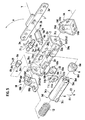
- FIG. 5 is an exploded perspective view of the hinge apparatus according to the embodiment of the present invention.
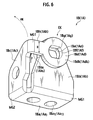
- FIG. 6 is a perspective view of a first principal portion of the hinge apparatus according to the embodiment of the present invention.
- FIG. 7 is a perspective view of a second principal portion of the hinge apparatus according to the embodiment of the present invention.
- FIG. 8 is a first perspective view of a third principal portion of the hinge apparatus according to the embodiment of the present invention.
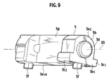
- FIG. 9 is a second perspective view of the third principal portion of the hinge apparatus according to the embodiment of the present invention.
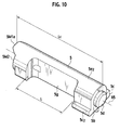
- FIG. 10 is a third perspective view of the third principal portion of the hinge apparatus according to the embodiment of the present invention.
- FIGS. 11A and 11B are perspective views of a fourth principal portion of the hinge apparatus according to the embodiment of the present invention.
- FIG. 12 is a plan view of the hinge apparatus according to the embodiment of the present invention.
- FIGS. 13A and 13B are explanatory views for use in illustrating rotation operation in the hinge apparatus according to the embodiment of the present invention.
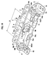
- FIG. 14 is a perspective view of the hinge apparatus according to the embodiment of the present invention.
- With reference to FIGS. 1 to 14, a hinge apparatus and an image displaying apparatus according to an embodiment of the present invention will be described in detail hereinafter. In this embodiment, as the hinge apparatus and the image displaying apparatus, a
hinge apparatus 50 and avideo camera 150 are thought. - As shown in FIG.1, the
video camera 150 includes thehinge apparatus 50, amain body portion 151 and animage displaying panel 152. Thehinge apparatus 50 opens and closes theimage displaying panel 152 with respect to themain body portion 151. FIG. 1 shows a state in which theimage displaying panel 152 is opened approximately 90° with respect to themain body portion 151. - A connection portion between the
main body portion 151 and theimage displaying panel 152 is apparently covered with ahinge cover 51. Thehinge apparatus 50 is contained in an internal part of thehinge cover 51. - On the front side of the
main body portion 151, alens portion 80 is provided. There are provided in an internal part of themain body portion 151 animaging element 81, asignal processing circuit 82 and a recording and reproducingportion 83. Theimaging element 81 converts an image of a subject that is obtained via thelens portion 80 into an electrical signal. Thesignal processing circuit 82 processes the electrical signal from theimaging element 81. The recording and reproducingportion 83 records an image signal output from thesignal processing circuit 82 and reproduces the recorded image signal. - Here, an image includes a still image and a moving image. In addition, as a recording medium, a magnetic tape, an optical disk, a magneto-optical disk, a solid-state memory or the like is employed. Furthermore, the recording medium may be the one contained in the
video camera 150, or the one removable. In addition, the recording medium may be externally located. At this time, thevideo camera 150 includes a communication unit for an external communication, and receives/transmits signals from/to the recording medium via the communication unit. An image of the subject, a reproduced image from the recording and reproducingportion 83, an operation image for operating thevideo camera 50 or the like is displayed on animage displaying portion 84 provided on theimage displaying panel 152. - The
image displaying panel 152, by thehinge apparatus 50, can obtain rotation forms as shown in FIGS. 2A to 2D. - A position in which the
image displaying portion 84 of theimage displaying panel 152 is held on the side of themain body portion 151 is to be a basic position. FIG. 2A shows a first rotation position in which theimage displaying panel 152 is turned approximately 90° (refer to an arrow A) about X-axis orthogonal to a face including an optical axis CL from the basic position (hereinafter, the X-axis is also referred to as a first rotation axis) . FIG. 2C shows a second rotation position in which theimage displaying panel 152 is turned 180° (refer to an arrow B) about Y-axis orthogonal to the X-axis from the first rotation position (hereinafter, the Y-axis is also referred to as a second rotation axis). FIG. 2B shows an intermediate position between the first rotation position and the second rotation position. FIG. 2D shows a third rotation position in which theimage displaying panel 152 is turned approximately 90° about the X-axis (refer to an arrow AA) from the second rotation position. - The first rotation position is a form to be preferably utilized when a user visually recognizes a screen (image displaying portion) 84 in a normal photographing. The second rotation position is a form to be preferably utilized when a photographed person, who is a subject, visually recognizes the
screen 84 in self-photographing. The third rotation position is a form to be preferably utilized when mainly the user visually recognizes a reproduced image. - The
hinge apparatus 50 can be turned independently about two rotation axes of the X-axis and the Y-axis orthogonal to a plane laid at right angles to the X-axis. Incidentally, the Y-axis is not limited to an axis crossing the X-axis. The Y-axis may be an axis orthogonal to the plane including the X-axis. Furthermore, although in this embodiment, a rotation angle about the X-axis from the basic position to the first rotation position is regulated to be 90°, and a rotation angle about the Y-axis from the first rotation position to the second rotation position is regulated to be 180°, the rotation angles about the X-axis and the Y-axis are not limited to these values. - The
hinge apparatus 50 is constructed as an assembly unit as shown in FIG. 3 and attached to thevideo camera 150 as shown in FIG. 4. FIG. 4, in a form of the basic position in which theimage displaying panel 152 is closed from the first rotation position shown in FIG. 2A, is a view showing members directly coupled to thehinge apparatus 50 with a removed face panel of theimage displaying panel 152 and a removed face panel of themain body portion 151. - The structure of the
hinge apparatus 50 will be described with reference to FIG. 3. - The
hinge apparatus 50 is coupled to a first opposite member by securing afirst bracket 1A and asecond bracket 1B disposed on the X-axis with respect to the first opposite member to which thehinge apparatus 50 is fixed. With the first and thesecond brackets base frame 2 is rotatably supported about the X-axis. Thebase frame 2 includes a pair of bent portions to be formed in a substantially U shape. - At the central portion of the
base frame 2, athird stud 9 is rotatably supported about the Y-axis coaxial with the axis of thethird stud 9. Thethird stud 9 is fixed to asub frame 3. Thebase frame 2 can be rotated in a range of a predetermined angle about the X-axis, with respect to the first andsecond brackets base frame 2, in the rotation of thebase frame 2, includes a cam mechanism M1 exhibiting a predetermined frictional force and providing a click feel at a specified angle. - The
sub frame 3 can be rotated in a range of a predetermined angle about the Y-axis, with respect to thebase frame 2. Thesub frame 3, in the rotation of thesub frame 3, includes a rotation regulating mechanism M2 exhibiting a predetermined frictional force and providing a click feel at a specified angle. The cam mechanism M1 and the rotation regulating mechanism M2 will be described below in detail. - As shown in FIG. 4, the
hinge apparatus 50 is attached integrally with themain body portion 151 by securing thefirst bracket 1A to afirst chassis 151a of themain body portion 151 with a screw (not shown) and by securing thesecond bracket 1B to asecond chassis 151b of themain body portion 151 with a screw (not shown). - The
sub frame 3 is engaged without looseness with an engaging portion 152a2 formed of a rib 152a1 provided at aframe 152a of theimage displaying panel 152, and secured with the rib 152a1 using a screw (not shown) to be attached integrally with theimage displaying panel 152. FIG. 4 shows a state in which a face panel of theimage displaying panel 152 is removed as described above, and shows alight unit 152b which the image displaying portion (liquid crystal display element) 84 contained in theimage displaying panel 152 includes, in theframe 152a. - Owing to such a structure, the
hinge apparatus 50 is attached to thevideo camera 150 to enable theimage displaying panel 152 to be opened and closed with respect to themain body portion 151. - Next, a detailed structure of the
hinge apparatus 50 will be described with reference to FIGS. 3, 5 to 14. First, each component of the first and thesecond brackets - The first and the
second brackets second bracket 1B is described referring to FIG. 6. Incidentally, in the following description, thesecond bracket 1B is referred to as a bracket. In FIG. 6, reference numerals of components of thefirst bracket 1A are shown in brackets for the reason of convenience. - The
bracket 1B is formed by pressing or bending a metal plate. Examples of metals that can be used include a stainless material or SPCC material of a thickness of 0.8 mm. In the case of the SPCC material, a surface thereof may be nitrided for a modification. - The
bracket 1B includes a bottom portion 1Ba, side portions 1Bb, 1Bc, and a superimposed side portion 1Bd. The bottom portion 1Ba is formed in a substantially rectangular shape. The side portions 1Bb and 1Bc are extended upward (in a direction of 90° with respect to the bottom portion 1Ba) from two adjacent sides at the bottom portion 1Ba respectively. The superimposed side portion 1Bd is extended from one side of the side portion 1Bc so as to overlap the outside surface of the side portion 1Bb. There is provided in the bottom portion 1Ba a hole 1ba1 to be used to secure thebracket 1B to the other member (for example, thesecond chassis 151b) with a screw. - In the side portion 1Bb and the superimposed side portion 1Bd, through holes 1Be and 1Bf which are coaxial and of which both sides are cut in D shape are formed respectively. The diameter of the through hole 1Bf of the superimposed side portion 1Bd is larger than that of the through hole 1Be of the side portion 1Bb, so that an abutment face 1Bg is formed on the surface of the side portion 1Bb. The through holes 1Be and 1Bf are not necessarily coaxial or of similar figures, but have only to be overlapped with each other to form the openings passing through the side portion 1Bb and the superimposed side portion 1Bd, and the below-described
studs - When forming the
bracket 1B, with respect to a plate material, in a blank-piercing process and a bending process, piercing of each through hole and bending of the bent portion MG1 at two points are firtly conducted at the same time, and subsequently bending of a bent portion MG2 is conducted. In this bending, the side portion 1Bb and the superimposed side portion 1Bd are not fully in close contact, but in a caulking process of afirst stud 7 as described below, the side portion 1Bb and the superimposed side portion 1Bd can be brought in close contact. Thefirst bracket 1A is formed in the same way. - Next, the
base frame 2 will be described with reference to FIG. 7. - The
base frame 2 is formed by pressing and bending a metal plate. Examples of metals that can be used include a stainless material or SPCC material of a thickness of 0.8 mm. In the case of the SPCC material, a surface thereof may be nitrided for a modification. - As shown in FIG. 7, the
base frame 2 includes abottom portion 2a of a substantially rectangular shape, alonger side portion 2b bent 90° from a longer edge of thebottom portion 2a, andshorter side portions longer side portion 2b (first and second shorter side portions 2cA and 2cB). - There are formed in the
shorter side portions hinge apparatus 50, this common axis is the x-axis. - In the
bottom portion 2a, a pair of long holes 2a1 and 2a1 is formed being spaced apart along the X-axis. The long holes 2a1 and 2a1 extend along the X-axis direction. In the central vicinity of thebottom portion 2a, in a position symmetrical with respect to a through hole 2b1 (described below) formed in thelonger side portion 2b, a pair of engaging holes 2a5 and 2a5 spaced apart is formed along the X-axis. - At a longer edge of the
bottom portion 2a on the opposite side of thelonger side portion 2b, there are provided an L-shaped uprising portion 2a2 and an uprising portion 2a3 that stand at approximately 90°. The L-shaped uprising portion 2a2 includes a notch 2a4 that is notched along the X-axis direction and formed in L shape, at the root side of the L-shaped uprising portion 2a2. - There is formed a through hole 2b1 substantially at the central portion of the
longer side portion 2b. The central axis of the through hole 2b1 is the Y-axis in thehinge apparatus 50. In positions symmetrically sandwiching the through hole 2b1, a pair of square holes 2b2 and 2b2 spaced apart from each other in the X-axis direction is formed. In one square hole 2b2, a protruding portion 2b3 is formed by half-punching so as to be adjacent to the one square hole 2b2 to protrude inward in a rectangular shape. - At the end edge on the
bottom portion 2a side of theshorter side portions bottom portion 2a are engaged with the cuts 2c2 and 2c2 respectively. Each extending portion 2a6 is formed such that an end of the extending portion 2a6 protrudes outward from an external surface of theshorter side portion 2c. Contact surfaces ST and ST, being the surfaces on longer side portions of the protruding portions 2a6t and 2a6t protruding from theshorter side portions second brackets - Next, a
cam shaft 5 will be described in detail with reference to FIGS. 8 to 10. - FIG. 8 is a view of the
cam shaft 5 taken substantially in the same perspective direction as the perspective direction of thecam shaft 5 shown in FIG. 5. FIG. 9 is a view of thecam shaft 5 taken from left inner lower side to the front side of FIG. 8. FIG. 10 is a view of thecam shaft 5 taken from diagonally above the top of thecam shaft 5 shown in FIG. 9. - The
cam shaft 5 has substantially a barrel shape, and is formed by coupling a semi-cylindrical portion 5e2 to a base portion 5e1 of a substantially rectangular parallelepiped. It is noted that axis X5 is to be a longitudinal direction of thecam shaft 5. Thecam shaft 5 is formed of a synthetic resin. Example of the resin to be used includes PBT (polybutylene terephthalate). To further improve strength, PBT including glass fibers may be employed. - In an
end face portion 5a of thecam shaft 5, a hole 5a1 of which central axis is the axis X5 is formed. A donut-like face, being a peripheral portion of the hole 5a1 is formed to be concavo-convex along a circumferential direction of thecam shaft 5. At the donut-like face, there is formed acam portion 5M in which the circumferential direction of thecam shaft 5 is a cam face. A shown in FIG. 8, thecam portion 5M includes a pair of convex portions 5M1 and 5M1 in opposing positions (in positions of being shifted 180°) with the axis X5 sandwiched. Each convex portion 5M1 is formed in a surface shape of being from a reference plane 5M2 of the donut-like face, via an inclined face 5M3, and leading to a most protruding face 5M1a of the convex portion 5M1. - On the side face of the base portion 5e1 on the
end face portion 5b side, a pair of protruding portions 5c1 and 5c2 protruding outward is provided (refer to FIG. 9 as well). Aspring guide 5d (refer to FIG. 9 as well) protruding cylindrically with the axis X5 being a central axis is provided at theend face portion 5b. The axis X5 is coaxial with the X-axis when thecam shaft 5 is attached to thebase frame 2. - As shown in FIG. 9, at the bottom portion 5e1a of the base portion 5e1, a pair of protruding
portions cam shaft 5. Furthermore, in an intermediate portion in the longitudinal direction of thecam shaft 5, aconvex portion 5g is formed such that thecam shaft 5 is of a substantially U shape. Hereinafter, the length in the longitudinal direction of theconvex portion 5g is referred to as a length L (refer to FIG. 10). - Next, a
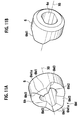
cam ring 6 will be described in detail referring to FIGS. 11A and 11B. - FIG. 11A is a perspective view of the
cam ring 6 viewed from a face side opposed to thecam shaft 5. FIG. 11B is a view of thecam ring 6 taken from a face side opposite to the face opposed to thecam shaft 5, that is, taken in the same direction as the perspective direction of FIG. 5. - The
cam ring 6 is formed of a synthetic resin. Examples of resins to be used include POM (polyacetal). In thecam ring 6, a through hole 6a of D cut on both faces is formed. The donut-like face, being a peripheral portion of the through hole 6a at anend face portion 6b of thecam ring 6, is formed to be concavo-convex along a circumferential direction of thecam ring 6. On the donut-like face, acam portion 6M letting the circumferential direction of the cam ring 6 a cam face is formed. As shown in FIG. 11A, thecam portion 6M includes a pair of convex portions 6M1 and 6M1 in opposed positions with axis X6 sandwiched (in positions of being shifted 180°). Each convex portion 6M1 is formed in a surface shape of being from a reference plane 6M2, being the donut-like face, via an inclined face 6M3, and leading to a most protruding face 6M1 of the convex portion 6M1. In thehinge apparatus 50, as described below, thecam ring 6 is integrated with thecam shaft 5 such that thecam portions cam shaft 5. Therefore, depending on a cam shape of thecam portions - In this embodiment, in an angle range in which the convex portions 5M1 and 5M1 of the
cam portion 5M are contacted with the convex portions 6M1 and 6M1 of thecam portion 6M, a rotation resistance is large. In an angle range in which the convex portions 5M1 and 5M1 of thecam portion 5M are not contacted with the convex portion 6M1 and 6M1 of thecam portion 6M, a rotation resistance is small. Thereby, this enables thevideo camera 150 to provide a click feel to a user. - Next, referring to FIG. 5, a first to a
third studs 7 to 9 will be described. - The
first stud 7 is formed of a basecylindrical portion 7a formed with D cuts on both sides of thefirst stud 7, and first andsecond shaft portions cylindrical portion 7a and having a smaller diameter than that of the basecylindrical portion 7a. On both sides of a tip end of thefirst shaft portion 7b, D cuts corresponding to two D cuts of the basecylindrical portion 7a are formed. - The
second stud 8 is formed of acircular flange portion 8a and ashaft portion 8b extending coaxially with theflange portion 8a. On both sides of a tip end of theshaft portion 8b, D cuts are formed. - The
third stud 9 is formed of a basecylindrical portion 9a and ashaft portion 9b extending coaxially from the basecylindrical portion 9a and having a smaller diameter than that of the basecylindrical portion 9a. On both sides of a tip end of theshaft portion 9b, D cuts are formed. Also on both sides of an end opposite from theshaft portion 9b at the basecylindrical portion 9a, D cutportions - The first to the
third studs 7 to 9 are made of a metal material. As materials thereof, for example, a stainless can be used. - With reference to FIG. 5, further, a
sub frame 3, aspring plate 10 and alock plate 11 will be described. - The
sub frame 3 possesses a substantially rectangular shape, and is formed by pressing and bending a metal plate. As metals that can be used, there is a stainless material or SPCC material of a thickness of 0.8 mm. In the case of the SPCC material, the surface thereof may be nitrided for modification. - On both end sides in a longitudinal direction of the
sub frame 3, a pair of throughholes sub frame 3 to the other part with screws are formed. As this other part, for example, there is theframe 152a of the image displaying panel 152 (refer to FIG. 4) . In specific, thesub frame 3 is engaged without a looseness with the engaging portion 152a2 that is formed at the rib 152a1 provided at theframe 152, and secured to theframe 152 through the throughholes 3a with screws (not shown) to be attached integrally with theimage displaying panel 152. - In a central vicinity of the
sub frame 3, asquare hole 3b letting the direction along the longitudinal direction of thesub frame 3 a longitudinal direction is formed. Thesquare hole 3b is fit to the D cutportions third stud 9. - The
spring plate 10 is made of a metal plate material (e.g. , a stainless plate or a phosphor bronze plate) having spring properties, and formed in a shape of a part of a cylindrical surface gently curved such that a central portion of thespring plate 10 protrudes. In a central vicinity of thespring plate 10, a throughhole 10a is formed. At a pair of side edges of thespring plate 10 exhibiting a straight line,bent portions spring plate 10 exhibiting a curved line,convex portions bent portions - The
lock plate 11 possesses a substantially circular shape, and is made of a metal plate such as stainless. At a central portion of thelock plate 11, a throughhole 11a of which both sides are D-cut is formed. At an outer edge of thelock plate 11 opposed to the D-cut side edges of the throughhole 11a,notches lock plate 11, a projectingportion 11c projecting outside in a radial direction is formed. - Next, the entire structure of the
hinge apparatus 50 will be described. Thehinge apparatus 50 includes two rotation axes of the X-axis and the Y-axis. In order of about the Y-axis and about the X-axis, a rotation structure of thehinge apparatus 50 will be described. - As shown in FIG. 5, the
third stud 9 is integrated with thesub frame 3 by fitting the D cutportions third stud 9 into thesquare hole 3b of thesub frame 3 to be caulked. Theshaft portion 9b of thethird stud 9 is inserted from the outside of thebase frame 2 in the through hole 2b1 of thelonger side portion 2b of thebase frame 2. Theshaft portion 9b having been inserted in the through hole 2b1 is inserted in the throughhole 10a of thespring plate 10. Thethird stud 9 is integrated with thelock plate 11 by inserting theshaft portion 9b having been inserted in the throughhole 10a into the throughhole 11a of thelock plate 11 to be caulked. - The
bent portions sprig plate 10 are engaged with the square holes 2b2 and 2b2 of thebase frame 2, whereby thespring plate 10 is regulated from rotating about the Y-axis. Moreover, caulking of theshaft portion 9b is conducted by collapsing a predetermined amount of thespring plate 10 via thelock plate 11, so that thespring plate 10, due to elastic repulsive force of thespring plate 10, biases thelock plate 11 in the Y-axis direction all the time. Therefore, thelock plate 11 can be rotated about the Y-axis while generating a predetermined frictional force with respect to thespring plate 10. That is, although thesub frame 3 is held by thebase frame 2 via thethird stud 9 by the frictional force between thespring plate 10 and thelock plate 11, thesub frame 3 can be rotated in a predetermined angle range about the Y-axis when force against this frictional force is applied to thesub frame 3. - Accompanied by the rotation about the Y-axis of the
lock plate 11, when thelock plate 11 has reached one of two second rotation angle positions, theconvex portions spring plate 10 are fit into thenotches image displaying panel 152 can be provided to a user. FIG. 5 shows an angular position in which thenotches convex portions lock plate 11, when thelock plate 11 has reached one of the two second rotation angle positions, one of both end face portions of the projectingportion 11c is contacted with one end face of a pair of the engaging holes 2a5 and 2a5 of thebase frame 2. Whereby, theimage displaying panel 152 is inhibited from rotating. Thus, thesub frame 3 can be rotated within a predetermined angle range about the Y-axis with respect to thebase frame 2. - First, the connection between the first and the
second brackets base frame 2 will be described. - As shown in FIGS. 3, 5 and 6, the
first shaft portion 7b of thefirst stud 7 is inserted into the through hole 2c1 of theshorter side portion 2c from the inside of thebase frame 2. Furthermore, thefirst shaft portion 7b is inserted through the through holes 1Af and 1Ae from the superimposed side portion 1Ad side of thefirst bracket 1A. - At the
first shaft portion 7b, on the root side of the portion provided with two D cuts, contact faces 7b1 and 7b1 laid at right angles to the axis of thefirst shaft portion 7b are formed. The contact faces 7b1 and 7b1 are brought in contact with the contact face 1Ag of thefirst bracket 1A (refer to FIG. 6), whereby the axis of thefirst stud 7 is aligned with the X-axis of thehinge apparatus 50. Due to that two D cuts of thefirst shaft portion 7b are brought in engagement with two D cuts of thefirst bracket 1A, thefirst shaft portion 7b is inhibited from rotating about the X-axis. - A distance L7 in the X-axis direction between each contact face 7b1 of the
first shaft portion 7b and the end face 7a1 of the basecylindrical portion 7a is set to be slightly larger than a plate thickness of theshorter side portion 2c of thebase frame 2. Therefore, when the tip end of thefirst shaft portion 7b having passed through the through hole 1Ae is secured by caulking, the base frame 2is rotatably supported with respect to thefirst bracket 1A without a resistance about the X-axis. Furthermore, the side portion 1Ab and superimposed side portion 1Ad of thefirst bracket 1A are pressed in the axial direction of the side portion 1Ab and the superimposed side portion 1Ad when the side portion 1Ab and the superimposed side portion 1Ad are caulked, so that they are connected integrally with thefirst stud 7 in a close contact state. - The
second bracket 1B and thebase frame 2 are connected to each other with thesecond stud 8. Theshaft portion 8b of thesecond stud 8 is inserted through the through hole 2c1 of the othershorter side portion 2c from the inside of thebase frame 2. Furthermore, theshaft portion 8b is inserted through the through holes 1Bf and 1Be from the superimposed side portion 1Bd side of thesecond bracket 1B. - At the
shaft portion 8b, on theflange portion 8a side at the portion provided with two D cuts, contact faces 8b1 and 8b1 laid at right angles to the axis of theshaft portion 8b are formed. The contact faces 8b1 and 8b1 are brought in contact with the contact face 1Bg of thesecond bracket 1B, whereby the axis of thesecond stud 8 is aligned with the X-axis of thehinge apparatus 50. Due to that two D cuts of theshaft portion 8b are brought in engagement with two D cuts of thesecond bracket 1B, theshaft portion 8b is inhibited from rotating about the X-axis. - A distance L8 in the X-axis direction between each contact face 8b1 of the
shaft portion 8b and an end face 8a1 on theshaft portion 8b side of theflange portion 8a is set to be slightly larger than a plate thickness of theshorter side portion 2c of thebase frame 2. Therefore, when the tip end of theshaft portion 8b having passed through the through hole 1Be is secured by caulking, thebase frame 2 is rotatably supported with respect to thesecond bracket 1B without a resistance about the X-axis. Furthermore, the side portion 1Bb and superimposed side portion 1Bd of thesecond bracket 1B are pressed in the axial direction of the side portion 1Bb and the superimposed side portion 1Bd when the side portion 1Bb and the superimposed side portion 1Bd are caulked, so that they are connected integrally with thesecond stud 8 in a close contact state. - Next, in rotation operation about the X-axis, the cam mechanism M1 providing a user with a frictional touch and a click feel will be described.
- As shown in FIG. 5, the base
cylindrical portion 7a andsecond shaft portion 7c of thefirst stud 7 are inserted in the through hole 6a of thecam ring 6. Here, two D cuts of the basecylindrical portion 7a are engaged with two D cuts of the through hole 6a, so that thecam ring 6 is inhibited from rotating with respect to thefirst stud 7. - On one end side of the
coil spring 12, thecoil spring 12 is engaged with theflange portion 8a of thesecond stud 8 to be located on the X-axis of thehinge apparatus 50. Although the shaft portion extending from theflange portion 8a of thesecond stud 8, in this embodiment, is only theshaft portion 8b, depending on an inside diameter of thecoil spring 12, another shaft portion extending on the opposite side from theshaft portion 8b (on thecoil spring 12 side) may be included. - The
cam shaft 5 is located on the X-axis such that thespring guide 5d (refer to FIG. 9) is engaged with the other side of thecoil spring 12 and thecam portion 5M is engaged with thecam portion 6M of thecam ring 6. Furthermore, in the hole 5a1 of thecam shaft 5, a tip end of theshaft portion 7c of thefirst stud 7 is inserted. - Here, the inside diameter of the
coil spring 12 is larger than the outside diameter of theflange portion 8a of thesecond stud 8 and the outside diameter of thespring guide 5d of thecam shaft 5, so that thecoil spring 12 and theflange portion 8a are engaged well with thecoil spring 12 and thespring guide 5d without an axial misalignment. - Owing to the above-mentioned construction, each member is set to be of a length in the X-axis direction such that the
coil spring 12 is compressed a predetermined amount in a longitudinal direction of thecoil spring 12. Thus, by elastic repulsive force of thecoil spring 12 generated by this compression, thecoil spring 12 biases thecam shaft 5 in a direction in which thecam portion 5M presses thecam portion 6M. - The
cam shaft 5 is inhibited from rotating about the X-axis with respect to thebase frame 2 and located so as to be capable of reciprocating and sliding a predetermined distance in the X-axis direction of thehinge apparatus 50. In specific, the protruding portions 5c1 and 5c1 of thecam shaft 5 are engaged with the notch 2a4 and the gap between the protruding portion 2b3 on thelonger side portion 2b and thebottom portion 2a respectively. In addition, the protrudingportions cam shaft 5 are engaged with the long holes 2a1 and 2a1 of the base frame 2 (refer to FIG. 7) respectively. - In these engagement structures, an engagement configuration on the
base frame 2 side is a notch or a hole extending in the X-axis direction, and the width in a direction orthogonal to the X-axis of these notch and hole is set to be substantially the same as the width of the protrusion or the protruding portion on thecam shaft 5 side. Therefore, thecam shaft 5 can be moved with respect to thebase frame 2, in a permissible range in the X-axis direction to be set depending on the shape of the long hole 2a1 or the notch 2a4. - FIG. 12 is a view of the
hinge apparatus 50 taken in a direction orthogonal to the X-axis and the Y-axis . As shown in FIG. 12, the L-shaped uprising portion 2a2 and the uprising portion 2a3 provided at thebase frame 2 are formed along the side face of thecam shaft 5. Thecam shaft 5 is held such that the looseness in a direction orthogonal to the X-axis is of a minimal amount, between the L-shaped uprising portion 2a2 and thelonger side portion 2b and between the uprising portion 2a3 and thelonger side portion 2b, so that this engagement structure prevents thecam shaft 5 from being released from on the X-axis. - In the
concave portion 5g provided at thecam shaft 5, thespring plate 10 and thelock plate 11 are contained. Therefore, by the portion at which thespring plate 10 and thelock plate 11 comes in theconcave portion 5g, a distance L2 between the X-axis and an outer surface of thelonger side portion 2b of thebase frame 2 can be shorter. As a result, thehinge apparatus 50 can be downsized further, and thus theimage displaying apparatus 150 using thehinge apparatus 50 can also be downsized. - A length L in the longitudinal direction of the
concave portion 5g is set to be in such a length as not to interfere with other members when thecam shaft 5 is integrated into thebase frame 2. Specifically, when the cam shat 5 is integrated into thebase frame 2, a pair of the protruding portions 5c1 and 5c1 is contained in thebase frame 2 in a position of not interfering with the L-shaped uprising portion 2a2 and the protruding portion 2b3 (indicated by an arrow E1 of FIG. 5), and thereafter slides in the X-axis direction (indicated by an arrow E2 of FIG. 5). Thus, the length L of theconcave portion 5g is set so as to obtain the escape with respect to a mating portion corresponding to sliding operation indicated by the arrow E2. - Next, with reference to FIGS. 13A and 13B, a regulation structure of a rotation range about the X-axis (hereinafter, referred to as a stopper structure) will be described. In FIGS. 13A and 13 B, only the
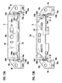
base frame 2 and the first and thesecond brackets base frame 2 and the first and thesecond brackets base frame 2 and the first and thesecond brackets base frame 2 is turned 90° in a direction indicated by an arrow A shown in FIG. 5 from the basic position. Incidentally, in the first rotation position, thebase frame 2 is regulated from being turned further in the direction indicated by the arrow A shown in FIG. 5. - The contact faces ST and ST, being a part of the faces of the extending portions 2a6 and 2a6 of the
bottom portion 2a of thebase frame 2 and being the diagonally shaded areas in FIG. 13A, are contacted with the side faces 1Ahs and 1Bhs of the connections 1Ah and 1Bh respectively. In the case where thebase frame 2 is turned more than 90° from the basic position in the direction indicated by the arrow A shown in FIG. 5, compressive forces F and F act on the connections 1Ah and 1Bh from the contact faces ST and ST. - With reference to the
second bracket 1B shown in FIG. 6, the action of the compressive force F will be described. - Due to that the bottom portion 1Ba is secured to the other member and that the superimposed side portion 1Bd and the side portion 1Bc are formed by bending with respect to the bottom portion 1Ba, when strong compressive force F is acted on the side face 1Bhs, the
second bracket 1B tends to deform in a direction indicated by a broken-line arrow HK. However, the superimposed side portion 1Bd is in close contact with the side portion 1Bc to be secured by caulking to thesecond stud 8. Therefore, since the compressive force F is received by the superimposed side portion 1Bd, the side portion 1Bc and thesecond stud 8 in cooperation, thesecond bracket 1B exhibits an extremely high strength with respect to a bend in the direction indicated by the broken-line arrow HK. Incidentally, the portion of the first and thesecond brackets base frame 2 positioned on the rotation side is contacted may be provided at the side portions 1Ac and 1Bc, or thefirst stud 7 and thesecond stud 8. - Whereas, due to that the contact faces ST and ST on the
main frame 2 side are the faces of the extending portions 2a6 and 2a6, when the contact faces ST and ST are brought in contact with the side faces 1Ahs and 1Bhs of the connections 1Ah and 1Bh, the extending portions 2a6 and 2a6, as shown in FIG. 7, are acted with reaction forces Fr and Fr against the compressive forces F and F. As described above, the extending portions 2a6 and 2a6 are engaged with the cuts 2c2 and 2c2 formed in theshorter side portions main frame 2 side also has an extremely high strength as a stopper. - Like this, the
hinge apparatus 50 possesses an extremely high stopper strength regulating the rotation about the X-axis , even if the main frame is going to be forcibly rotated with exceeding a regulated angular position, it is much less likely to be broken. Incidentally, as described above, due to that both the first and thesecond brackets second brackets second brackets main frame 2 side that are contacted with each other are constructed to be of the above-described configuration, a high strength can be obtained to be favorable. However, either one of the first andsecond brackets main frame 2 side may be of the above-described configuration or construction. Even in this case, a high rotation-regulating strength can be obtained. - In the
image displaying apparatus 150 provided with thehinge apparatus 50, even if a user is going to open theimage displaying panel 152 with exceeding a predetermined rotation-regulating angular position (for example, 90°), thehinge apparatus 50 is extremely hard to be broken, so that a significantly high reliability can be obtained. In the stopper structure about the X-axis , thebracket 1A (1B) can be regarded to construct such a closed loop (annular structure) as the bottom portion 1Aa (1Ba) → the side portion 1Ac (1Bc) → the superimposed side portion 1Ad (1Bd) → the stud 7 (8) → the side portion 1Ab (1Bb) → the bottom portion 1Aa (1Ba). In addition, the compressive force F is received at any component of this loop. - Normally, such a closed loop configuration is extremely hard to deform from the inside to the outside, so that the above-described stopper structure is thought to have a high strength with respect to the deformation.
- With tests conducted by the inventors, as compared with a comparative example in which the loop structure is cut, specifically the comparative example in which the stud 7 (8) is removed, in respect of the deformation of the connection 1Ah (1Bh) provided by the compressive force F, the above-described loop structure is confirmed to have not less than twice the strength. That is, even if the thickness of the components is made smaller or the shape thereof is made smaller, the strength equal to or higher than that of the comparative example will be obtained, thus enabling cost down or a further downsizing.
- In the
hinge apparatus 50, owing the above-described construction, thesub frame 3 is turned in a direction indicated by an arrow A1 about the X-axis with respect to the first and thesecond brackets main frame 2 that is coupled to thesub frame 3 through thethird hinge 9 is turned integrally with thesub frame 3 as well. Accompanied by this rotation of themain frame 2, thecam shaft 5 and thecoil spring 12 biasing thecam shaft 5 toward thecam ring 6 side that are held in themain frame 2 are rotated integrally. - On the other hand, the
cam ring 6 is inhibited from rotating with respect to thefirst bracket 1A with thefirst stud 7, so that by the rotation of themain frame 2, thecam portion 5M of thecam shaft 5 and thecam portion 6M of thecam ring 6 are slid about the X-axis while being biased to each other. - Accompanied by the rotation of the
main frame 2, thecam shaft 5 reciprocates in the X-axis direction depending on the cam shape of thecam portions coil spring 12 is changed, and biasing force biasing thecam shaft 5 is changed. This change of the biasing force is touched as a rotational feel by a user, as well as recognized as a click feel. - The
cam shaft 5 is only reciprocated in the X-axis direction with respect to themain frame 2 and thecam shaft 5 is provided with theconcave portion 5g recessed in an axial range not less than the stroke of this reciprocation. Thus, not depending on the rotation angular position of themain frame 2, the rotation-regulating mechanism M2 about the Y-axis can be housed in theconcave portion 5g, and thus, thehinge apparatus 50 can be made extremely compact. - In the
hinge apparatus 50 , depending on the cam shape of thecam portions - Moreover, the
coil spring 12, thecam shaft 5 and thecam ring 6 can be easily replaced. This replacement can be conducted due to that thehinge apparatus 50 is constructed to include no shaft member passing through each of the first and thesecond brackets base frame 2 to be secured to the first and thesecond brackets second studs 7 and 8 (refer to FIG. 14) is set to be longer than an entire length Lc of the cam shat 5 (refer to FIG. 10). Whereby, the cameshaft 5 can be removed without being caught by the first and thesecond studs cam shaft 5 is sufficient on the supposition of letting the most protruding face 5M1a of thecam portion 5M a reference. However, depending on a cam shape, the entire length Lc may be determined by letting the reference plane 5M2 a reference. In this respect, either case may be set depending on a cam position when thecam shaft 5 is removed. - The replacement of the
coil spring 12, thecam shaft 5 and thecam ring 6 will be described specifically. First, by the compression of thecoil spring 12 in the X-axis direction, thecoil spring 12 is disengaged from theflange portion 8a of thesecond stud 8 and thespring guide 5d of thecam shaft 5 to be removed from on the X-axis . Subsequently, by sliding thecam shaft 5 in the direction opposite to an arrow E2 in FIG. 5, thecam shaft 5 is disengaged from themain frame 2, and thus thecam shaft 5 can be easily removed. When thecam shaft 5 is removed from themain frame 2, thecam ring 6 comes off from thesecond shaft portion 7c of thefirst stud 7 by being axially slid, so that thecam ring 6 can be removed. FIG. 14 shows a state in which thecoil spring 12, thecam shaft 5 and thecam ring 6 are removed from themain frame 2. Like this, in thehinge apparatus 50, thecoil spring 12, thecam shaft 5 and thecam ring 6 can be easily replaced independently of each other, so that by the replacement of or in combination of the other coil spring, cam shaft, or cam ring of different spring constants, cam portion configurations, protruding positions of a cam portion, a rotation specification (rotation resistance, click feel, rotation angular position where the click feel can be obtained) in rotation about the X-axis can be freely or easily set. - Even if members other than the
coil spring 12, thecam shaft 5 and thecam ring 6 are shared, thehinge apparatus 50 can be used in a variety of image displaying apparatuses of different rotation specifications of an image displaying panel, so that an extremely inexpensiveimage displaying apparatus 150 can be provided. - From the viewpoint that in the
hinge apparatus 50, arotation body 50B is made to turn about the X-axis with respect to the fixedbody 50A, the fixedbody 50A includes the first and thesecond brackets second studs cam ring 6, and therotation body 50B includes thebase frame 2, thecoir spring 12 and thecam shaft 5. Thethird stud 9 and the like turned along with thebase frame 2 are included in therotation body 50B. - The hinge apparatus according to the present invention is not limited to the above-described construction and procedure, but may be modified without departing from the gist of the present invention.
- A lubricant such as grease may be applied to a sliding portion of each member.
- The length of the
cam shaft 5 or thecam ring 6 is not limited to the above-described axial length. Even in any shape (length), the concave portion housing the rotation-regulating mechanism M2 is desired to form somewhere. - D cut on both faces of engaging portion may be D cut on one face of the engaging portion.
- An image displaying apparatus to which the hinge apparatus is applicable is not limited to a video camera, and insofar as an apparatus is provided with a thin image displaying panel, it is not limited to a video camera. The hinge apparatus can be applied to various apparatuses, for example, a digital still camera, a notebook computer, a mobile phone, PDA (Personal Digital Assistants), a mobile television, a game apparatus and a portable optical disk player.
- Even if an image displaying panel is a panel having a function other than displaying an image, for example, an operation panel on which operation buttons are arranged, the hinge apparatus can be applied.
- Although the above-described hinge apparatus is constructed to include two axes of the X-axis and the Y-axis, it may be constructed to turn only about the X-axis. Even in this case, a coil spring, a cam shaft and a cam ring are replaced, and thus a hinge of an arbitrary rotation specification can be easily obtained.
- Although in the above-described hinge apparatus, as a biasing member to bias a cam shaft, a coil spring is employed, it is not limited to this coil spring, but an elastic member such as rubber may be employed. Furthermore, an elastic member such as rubber and a coil spring may be used in combination.
Claims (11)
- A hinge apparatus (50) comprising:a rotation body (50B); anda fixed body (50A) configured to support the rotation body (50B) rotatably about a rotation axis (X),whereinthe rotation body (50B) includes:a base frame (2) having: a base body portion (2b) extending along the rotation axis (X); and a side portion (2cA) extending from an end of the base body portion (2b) in a direction orthogonal to the rotation axis (X) and formed with a first through hole (2c1) with the rotation axis (X) as a central axis,whereinthe fixed body (50A) includes:a bracket (1A) having: a base portion (1Aa); a first side portion (1Ab) extending from a first edge of the base portion (1Aa); a second side portion (1Ac) extending from a second edge of the base portion (1Aa); a superimposed portion (1Ad) extending from the second side portion (1Ac) so as to be overlapped with the first side portion (1Ab); a second through hole (1Ae) passing through the first side portion (1Ab); and a third through hole (1Af) passing through the superimposed portion (1Ad) and communicating with the second through hole (1Ae); anda stud (7) inserted through the first through hole (2c1), the second through hole (1Ae) and the third through hole (1Af), and secured to the bracket (1A) so as to rotatably support the base frame (2) with respect to the bracket (1A), andwhereinthe base frame (2) has a contact portion (2a6) to be in contact with at least one of the first side portion (1Ab), the superimposed portion (1Ad) and the stud (7) in a predetermined angular position with respect to the bracket (1A), andby the contact, the rotation body (50B) is regulated from rotating with respect to the fixed body (50A).
- A hinge apparatus (50) comprising:a rotation body (50B); anda fixed body (50A) configured to support the rotation body (50B) rotatably about a rotation axis (X),whereinthe rotation body (50B) includes a base frame (2) having:a base body portion (2b) extending along the rotation axis (X);a side portion (2cA) extending from an end of the base body portion (2b) in a direction orthogonal to the rotation axis (X) and having a first through hole (2c1) with the rotation axis (X) as a central axis and a cut portion (2c2) formed by cutting an outer edge of the side portion (2cA); anda longer side portion (2a) having an extending portion (2a6) and extending from an end of the base body portion (2b) outwardly of the base body portion (2b) along the rotation axis (X),the extending portion (2a6) is engaged with the cut portion (2c2) and has a protruding portion (2a6t) protruding outward beyond an outer surface of the side portion (2c) on a tip end side of the extending portion (2a6),whereinthe fixed body (50A) includes:a bracket (1A) having a second through hole (1Ae); anda stud (7) inserted through the first through hole (2c1) and the second through hole (1Ae) and secured to the bracket (1A) so as to rotatably support the base frame (2) with respect to the bracket (1A), andwhereinthe protruding portion (2a6t) of the base frame (2) is in contact with at least one of the bracket (1A) and the stud (7) in a predetermined angular position with respect to the bracket (1A), and thereby the rotation body (50B) is regulated from rotating with respect to the fixed body (50A).
- A hinge apparatus (50) comprising :a rotation body (50B); anda fixed body (50A) configured to support the rotation body (50B) rotatably about a rotation axis (X),whereinthe rotation body (50B) includes a base frame (2) having:a base body portion (2b) extending along the rotation axis (X);a side portion (2c) extending from an end of the base body portion (2b) in a direction orthogonal to the rotation axis (X) and having a first through hole (2c1) with the rotation axis (X) as a central axis and a cut portion (2c2) formed by cutting an outer edge of the side portion (2c); anda longer side portion (2a) having an extending portion (2a6) and extending from an end of the base body portion (2b) outwardly of the base body portion (2b) along the rotation axis (X),the extending portion (2a6) is engaged with the cut portion (2c2) and has a protruding portion (2a6t) protruding outward beyond an outer surface of the side portion (2c) on a tip end side of the extending portion (2a6),whereinthe fixed body (50A) includes:a bracket (1A) having: a base portion (1Aa); a first side portion (1Ab) extending from a first edge of the base portion (1Aa); a second side portion (1Ac) extending from a second edge of the base portion (1Aa); a superimposed portion (1Ad) extending from the second side portion (1Ac) so as to be overlapped with the first side portion (1Ab); a second through hole (1Ae) passing through the first side portion (1Ab); and a third through hole (1Af) passing through the superimposed portion (1Ad) and communicating with the second through hole (1Ae); anda stud (7) inserted through the first through hole (2c1), the second through hole (1Ae) and the third through hole (1Af), and secured to the bracket (1A) so as to rotatably support the base frame (2) with respect to the bracket (1A), andwhereinthe protruding portion (2a6t) of the base frame (2) is in contact with at least one of the first side portion (1Ab), the superimposed portion (1Ad) and the stud (7) in a predetermined angular position with respect to the bracket (1A), and thereby the rotation body (50B) is regulated from rotating with respect to the fixed body (50A).
- An image displaying apparatus (150) comprising:a main body portion (151);an image displaying portion (152) configured to display an image; anda hinge apparatus (50) configured to cause the image displaying portion (152) to turn about at least one axis with respect to the main body portion (151),whereinthe hinge apparatus (50) comprises:a rotation body (50B); anda fixed body (50A) configured to support the rotation body (50B) rotatably about a rotation axis (X),the rotation body (50B) including:a base frame (2) having a base body portion (2b) extending along the rotation axis (X); and a side portion (2cA) extending from an end of the base body portion (2b) in a direction orthogonal to the rotation axis (X) and formed with a first through hole (2c1) with the rotation axis (X) as a central axis, andthe fixed body (50A) including:a bracket (1A) having: a base portion (1Aa); a first side portion (1Ab) extending from a first edge of the base portion (1A); a second side portion (1Ac) extending from a second edge of the base portion (1Aa); a superimposed portion (1Ad) extending from the second side portion (1Ac) so as to be overlapped with the first side portion (1Ab); a second through hole (1Ae) passing through the first side portion (1Ab); and a third through hole (1Af) passing through the superimposed portion (1Ad) and communicating with the second through hole (1Ae); anda stud (7) inserted through the first through hole (2c1), the second through hole (1Ae) and the third through hole (1Af), and secured to the bracket (1A) so as to rotatably support the base frame (2) with respect to the bracket (1A), andwhereinthe base frame (2) includes a contact portion (2a6) to be in contact with at least one of the first side portion (1Ab), the superimposed portion (1Ad) and the stud (7) in a predetermined angular position with respect to the bracket (1A),by the contact, the rotation body (50B) is regulated from rotating with respect to the fixed body (50A),the fixed body (50A) is coupled to the main body portion (151), andthe rotation body (50B) is coupled to the image displaying portion (152).
- An image displaying apparatus (150) comprising:a main body portion (151);an image displaying portion (152) configured to display an image; anda hinge apparatus (50) configured to cause the image displaying portion (152) to turn about at least one axis with respect to the main body portion (151),whereinthe hinge apparatus (50) comprises:a rotation body (50B); anda fixed body (50A) configured to support the rotation body (50B) rotatably about a rotation axis (X);the rotation body (50B) including a base frame (2) having:a base body portion (2b) extending along the rotation axis (X);a side portion (2cA) extending from an end of the base body portion (2b) in a direction orthogonal to the rotation axis (X) and having: a first through hole (2c1) with the rotation axis (X) as a central axis; and a cut portion (2c2) formed by cutting an outer edge of the side portion (2cA); anda longer side portion (2a) having an extending portion (2a6) and extending from an end of the base body portion (2b) outwardly of the base body portion (2b) along the rotation axis (X),the extending portion (2a6) is engaged with the cut portion (2c2) and has a protruding portion (2a6t) protruding outward beyond the outer surface of the side portion (2c) on a tip end side of the extending portion (2a6), andthe fixed body (50A) including:a bracket (1A) having a second through hole (1Ae); anda stud (7) inserted through the first through hole (2c1) and the second through hole (1Ae) and secured to the bracket (1A) so as to rotatably support the base frame (2) with respect to the bracket (1A), andwhereinthe protruding portion (2a6t) of the base frame (2) is in contact with at least one of the bracket (1A) and the stud (7) in a predetermined angular position with respect to the bracket (1A), and thereby the rotation body (50B) is regulated from rotating with respect to the fixed body (50A), the fixed body (50A) is coupled to the main body portion (151), andthe rotation body (50B) is coupled to the image displaying portion (152).
- An image displaying apparatus (150) comprising:a main body portion (151);an image displaying portion (152) configured to display an image; anda hinge apparatus (50) configured to cause the image displaying portion (152) to turn about at least one axis with respect to the main body portion (151),whereinthe hinge apparatus (50) comprises:a rotation body (50B); anda fixed body (50A) configured to support the rotation body (50B) rotatably about a rotation axis (X),the rotation body (50B) including a base frame (2) having:a base body portion (2b) extending along the rotation axis (X);a side portion (2c) extending from an end of the base body portion (2b) in a direction orthogonal to the rotation axis (X) and having: a first through hole (2c1) with the rotation axis (X) as a central axis; and a cut portion (2c2) formed by cutting an outer edge of the side portion (2c); anda longer side portion (2a) having an extending portion (2a6) and extending from an end of the base body portion (2b) outwardly of the base body portion (2b) along the rotation axis (X),the extending portion (2a6) is engaged with the cut portion (2c2) and has a protruding portion (2a6t) protruding outward beyond the outer surface of the side portion (2c) on a tip end side of the extending portion (2a6), andthe fixed body (50A) including:a bracket (1A) having: a base portion (1Aa); a first side portion (1Ab) extending from a first edge of the base portion (1Aa); a second side portion (1Ac) extending from a second edge of the base portion (1Aa) ; a superimposed portion (1Ad) extending from the second side portion (1Ac) so as to be overlapped with the first side portion (1Ab); a second through hole (1Ae) passing through the first side portion (1Ab) ; and a third through hole (1Af) passing through the superimposed portion (1Ad) and communicating with the second through hole (1Ae); anda stud (7) inserted through the first through hole (2c1), the second through hole (1Ae) and the third through hole (1Af) and secured to the bracket (1A) so as to rotatably support the base frame (2) with respect to the bracket (1A), andwhereinthe protruding portion (2a6t) of the base frame (2) is in contact with at least one of the first side portion (1Ab), the superimposed portion (1Ad) and the stud (7) in a predetermined angular position with respect to the bracket (1A), and thereby the rotation body (50B) is regulated from rotating with respect to the fixed body (50A);the fixed body (50A) is coupled to the main body portion (151); andthe rotation body (50B) is coupled to the image displaying portion (152).
- A hinge apparatus (50) comprising:a rotation body (50B); anda fixed body (50A) configured to support the rotation body (50B) rotatably about one rotation axis (X),whereinthe rotation body (50B) includes:a base frame (2) having: a base body portion (2b) extending along the one rotation axis (X); a first side portion (2cA) extending from a first end of the base body portion (2b) in a direction orthogonal to the one rotation axis (X) and formed with a first through hole (2c1) with the one rotation axis (X) as a central axis; and a second side portion (2cB) extending from a second end of the base body portion (2b) in a direction orthogonal to the one rotation axis (X) and formed with a second through hole (2c1) with the one rotation axis (X) as a center axis;a first cam body (5) formed with a first cam face (5M) at one end thereof, suppresses by the base body portion (2b) the rotation about the one rotation axis (X) with respect to the base body portion (2b), and supported by the base body portion (2b) so as to be movable in a direction of the one rotation axis (X); anda biasing body (12) disposed between the first cam body (5) and the second side portion (2cB) and biasing the first cam body (5) toward the first side portion (2cA),whereinthe fixed body (50A) includes:a first shaft (7) inserted in the first through hole (2c1) of the first side portion (2cA) and supporting the base frame (2) rotatably about the one rotation axis (X);a second shaft (8) inserted in the second through hole (2c1) of the second side portion (2CB) and supporting the base frame (2) rotatably about the one rotation axis (X) ; anda second cam body (6) formed with a second cam face (6M) at one end thereof and supported by the first shaft (7) between the first cam body (5) and the first side portion (2cA) so that the rotation about the one rotation axis (X) with respect to the first shaft (7) is suppressed, andwhereinthe first cam face (5M) and the second cam face (6M) are pressed and contacted with each other by a bias of the biasing body (12).
- The hinge apparatus according to claim 7, wherein a distance (Ls) between tip ends of the first shaft (7) and the second shaft (8) is longer than that of the first cam body (5) in a direction of the one rotation axis (X).
- The hinge apparatus according to claim 7 , wherein the base body portion (2b) of the base frame (2) includes:a third through hole (2b1) with the other rotation axis (Y) orthogonal to a plane containing the one rotation axis (X) as a central axis;a third shaft (9) inserted from the outside in the third through hole (2b1);a shaft fixing portion (11) fixed to a tip end of the third shaft (9) having been inserted, sandwiching the base body portion (2b) between the shaft fixing portion (11) and the third shaft (9), and rotating about the other rotation axis (Y) with respect to the base frame (2); anda concave portion (5g) provided at the side portion of the first cam body (5), andwhereinthe shaft fixing portion (11) comes in the concave portion (5g).
- An image displaying apparatus (150) comprising:a main body portion (151);an image displaying portion (152) configured to display an image; anda hinge apparatus (50) configured to cause the image displaying portion (152) to turn about at least one axis with respect to the main body portion (151),whereinthe hinge apparatus (50) comprises:a rotation body (50B); anda fixed body (50A) configured to support the rotation body (50B) rotatably about one rotation axis (X),the rotation body (50B) including:a base frame (2) having: a base body portion (2b) extending along the one rotation axis (X) ; a first side portion (2cA) extending from a first end of the base body portion (2b) in a direction orthogonal to the one rotation axis (X) and formed with a first through hole (2c1) with the one rotation axis (X) as a central axis; and a second side portion (2cB) extending from a second end of the base body portion (2b) in a direction orthogonal to the one rotation axis (X) and formed with a second through hole (2c1) with the one rotation axis (X) as a center axis;a first cam body (5) formed with a first cam face (5M) at one end of the first cam body (5), suppresses by the base body portion (2b) the rotation about the one rotation axis (X) with respect to the base body portion (2b), and supported by the base body portion (2b) so as to be movable in a direction of the one rotation axis (X); anda biasing body (12) disposed between the first cam body (5) and the second side portion (2cB) and biasing the first cam body (5) toward the first side portion (2cA); andthe fixed body (50A) including:a first shaft (7) inserted in the first through hole (2c1) of the first side portion (2cA) and supporting the base frame (2) rotatably about the one rotation axis (X);a second shaft (8) inserted in the second through hole (2c1) of the second side portion (2cB) and supporting the base frame (2) rotatably about the one rotation axis (X); anda second cam body (6) formed with a second cam face (6M) at one end of the second cam body (6) and supported by the first shaft (7) between the first cam body (5) and the first side portion (2cA) so that the rotation about the one rotation axis (X) with respect to the first shaft (7) is suppressed, andwhereinthe first cam face (5M) and the second cam face (6M) are pressed and contacted with each other by a bias of the biasing body (12),the fixed body (50A) is coupled to the main body portion (151), andthe rotation body (50B) is coupled to the image displaying portion (152).
- An image displaying apparatus (150) comprising:a main body portion (151);an image displaying portion (152) configured to display an image; anda hinge apparatus (50) configured to cause the image displaying portion (152) to turn about at least one axis with respect to the main body portion (151),whereinthe hinge apparatus (50) comprises:a rotation body (50B); anda fixed body (50A) configured to support the rotation body (50B) rotatably about one rotation axis (X),the rotation body (50B) including:a base frame (2) having: a base body portion (2b) extending along the one rotation axis (X); a first side portion (2cA) extending from a first end of the base body portion (2b) in a direction orthogonal to the one rotation axis (X) and formed with a first through hole (2c1) with the one rotation axis (X) as a central axis; and a second side portion (2cB) extending form a second end of the base body portion (2b) in a direction orthogonal to the one rotation axis (X) and formed with a second through hole (2c1) with the one rotation axis (X) as a center axis;a first cam body (5) formed with a first cam face (5M) at one end of the first cam body, suppresses by the base body portion (2b) the rotation about the one rotation axis (X) with respect to the base body portion (2b), and supported by the base body portion (2b) so as to be movable in a direction of the one rotation axis (X); anda biasing body (12) disposed between the first cam body (5) and the second side portion (2cB) and biasing the first cam body (5) toward the first side portion (2cA), andthe fixed body (50A) including:a first shaft (7) inserted in the first through hole (2c1) of the first side portion (2cA) and supporting the base frame (2) rotatably about the one rotation axis (X) ;a second shaft (8) inserted in the second through hole (2c1) of the second side portion (2cB) and supporting the base frame (2) rotatably about the one rotation axis (X); anda second cam body (6) formed with a second cam face (6M) at one end of the second cam body (6) and supported by the first shaft (7) between the first cam body (5) and the first side portion (2cA) so that the rotation about the one rotation axis (X) with respect to the first shaft (7) is suppressed, andthe first cam face (5M) and the second cam face (6M) are pressed and contacted with each other by a bias of the biasing body (12),whereinthe base body portion (2b) of the base frame (2) includes:a third through hole (2b1) with the other rotation axis (Y) orthogonal to a plane containing the one rotation axis (X) as a central axis;a third shaft (9) inserted from the outside in the third through hole (2b1);a shaft fixing portion (11) fixed to a tip end of the third shaft (9) having been inserted, sandwiching the base body portion (2b) between the shaft fixing portion (11) and the third shaft (9), and rotating about the other rotation axis (Y) with respect to the base frame (2); anda concave portion (5g) provided at the side portion of the first cam body (5), andwhereinthe shaft fixing portion (11) comes in the concave portion (5g),the fixed body (50A) is coupled to the main body portion (151), andthe third shaft (9) is coupled to the image displaying portion (152).
Applications Claiming Priority (2)
| Application Number | Priority Date | Filing Date | Title |
|---|---|---|---|
| JP2006201237 | 2006-07-24 | ||
| JP2006201238 | 2006-07-24 |
Publications (3)
| Publication Number | Publication Date |
|---|---|
| EP1885118A2 true EP1885118A2 (en) | 2008-02-06 |
| EP1885118A3 EP1885118A3 (en) | 2015-11-18 |
| EP1885118B1 EP1885118B1 (en) | 2020-02-26 |
Family
ID=38668838
Family Applications (1)
| Application Number | Title | Priority Date | Filing Date |
|---|---|---|---|
| EP07014536.2A Active EP1885118B1 (en) | 2006-07-24 | 2007-07-24 | Hinge apparatus and image displaying apparatus |
Country Status (4)
| Country | Link |
|---|---|
| US (1) | US7784156B2 (en) |
| EP (1) | EP1885118B1 (en) |
| KR (1) | KR100867434B1 (en) |
| CN (1) | CN101113756B (en) |
Cited By (1)
| Publication number | Priority date | Publication date | Assignee | Title |
|---|---|---|---|---|
| EP2098939A3 (en) * | 2008-03-07 | 2014-03-12 | Sony Mobile Communications Japan, Inc. | Biaxial hinge device and portable terminal device |
Families Citing this family (12)
| Publication number | Priority date | Publication date | Assignee | Title |
|---|---|---|---|---|
| JP2006005579A (en) * | 2004-06-16 | 2006-01-05 | Sony Corp | Imaging device |
| JP5762018B2 (en) * | 2011-01-28 | 2015-08-12 | 加藤電機株式会社 | Biaxial hinge and electronic device provided with the biaxial hinge |
| US20120275614A1 (en) * | 2011-04-28 | 2012-11-01 | Sony Corporation | Noise cancellation unit |
| CN102840220A (en) * | 2011-06-21 | 2012-12-26 | 鸿富锦精密工业(深圳)有限公司 | hinge structure |
| JP6061460B2 (en) * | 2011-11-29 | 2017-01-18 | 加藤電機株式会社 | Biaxial hinge and electronic device provided with the biaxial hinge |
| USD698381S1 (en) * | 2012-07-30 | 2014-01-28 | JVC Kenwood Corporation | Camcorder |
| USD696328S1 (en) * | 2012-11-05 | 2013-12-24 | Panasonic Corporation | Video camera |
| JP5955908B2 (en) * | 2014-08-07 | 2016-07-20 | 三菱製鋼株式会社 | Switchgear and electronic device |
| JP6541316B2 (en) * | 2014-08-27 | 2019-07-10 | キヤノン株式会社 | Electronic device provided with hinge unit and hinge unit |
| CN106555814B (en) * | 2015-09-25 | 2024-01-09 | 昆山玮硕恒基智能科技股份有限公司 | Fixing device for hinge and electronic equipment component |
| CN105972398B (en) * | 2016-07-01 | 2017-12-08 | 北京小鸟看看科技有限公司 | A kind of camera bracket of band damping |
| CN107092153A (en) * | 2017-04-28 | 2017-08-25 | 深圳东方红鹰科技有限公司 | With the detection camera apart from induction lock |
Family Cites Families (20)
| Publication number | Priority date | Publication date | Assignee | Title |
|---|---|---|---|---|
| JPH08125890A (en) * | 1994-10-21 | 1996-05-17 | Sony Corp | Video camera |
| JP3220412B2 (en) | 1997-05-12 | 2001-10-22 | 株式会社ニフコ | Hinge mechanism and hinge unit |
| KR19990047369A (en) * | 1997-12-04 | 1999-07-05 | 구자홍 | LCD part rotation / screen inversion device of digital still camera |
| JP3031903B1 (en) | 1998-12-25 | 2000-04-10 | 三菱製鋼株式会社 | Hinge mechanism |
| JP3669244B2 (en) * | 2000-03-24 | 2005-07-06 | ソニー株式会社 | Imaging device |
| US6357712B1 (en) * | 2000-06-28 | 2002-03-19 | Lu Sheng-Nan | Pivot for a screen |
| JP4063571B2 (en) * | 2002-04-10 | 2008-03-19 | 日本電気株式会社 | Foldable mobile communication terminal |
| US6796541B2 (en) * | 2002-08-29 | 2004-09-28 | Shin Zu Shing Co., Ltd. | Support for an LCD monitor |
| US7123304B2 (en) * | 2002-11-27 | 2006-10-17 | Shin Zu Shing Co., Ltd. | Hinge for an LCD monitor of a video movie camera |
| KR100492554B1 (en) * | 2002-11-29 | 2005-06-02 | 엘지전자 주식회사 | Hinge apparatus for mobile phone |
| JP2004214396A (en) * | 2002-12-27 | 2004-07-29 | Olympus Corp | Hinge apparatus, hinge unit, and electronic appliance |
| KR101025402B1 (en) * | 2003-02-25 | 2011-03-28 | 교세라 가부시키가이샤 | Imaging Device, Cam Device and Optical Zoom Mechanism |
| KR101018375B1 (en) * | 2003-05-06 | 2011-03-02 | 삼성전자주식회사 | Hinge device and wiring member used for the hinge device |
| JP2005155779A (en) * | 2003-11-26 | 2005-06-16 | Victor Co Of Japan Ltd | Hinge mechanism and electronic device using the same |
| JP2006029532A (en) * | 2004-07-21 | 2006-02-02 | Sando Kogyosho:Kk | Inclined support device for movable body |
| US20060107492A1 (en) * | 2004-11-25 | 2006-05-25 | Sheng-Hao Chang | Rotary hinge for rotationally coupling image capturing device with display panel |
| JP2007281345A (en) * | 2006-04-11 | 2007-10-25 | Sony Corp | Stand rotating mechanism and electronic device |
| CN100489324C (en) * | 2006-07-07 | 2009-05-20 | 鸿富锦精密工业(深圳)有限公司 | Hinge device |
| US7469449B2 (en) * | 2006-07-18 | 2008-12-30 | Shin Zu Shing Co., Ltd. | Rotatable hinge |
| KR100754524B1 (en) * | 2006-09-19 | 2007-09-03 | 삼성전자주식회사 | Hinge device and electronic device having same |
-
2007
- 2007-07-11 KR KR1020070069575A patent/KR100867434B1/en not_active Expired - Fee Related
- 2007-07-24 CN CN2007101386447A patent/CN101113756B/en not_active Expired - Fee Related
- 2007-07-24 EP EP07014536.2A patent/EP1885118B1/en active Active
- 2007-07-24 US US11/878,336 patent/US7784156B2/en active Active
Cited By (1)
| Publication number | Priority date | Publication date | Assignee | Title |
|---|---|---|---|---|
| EP2098939A3 (en) * | 2008-03-07 | 2014-03-12 | Sony Mobile Communications Japan, Inc. | Biaxial hinge device and portable terminal device |
Also Published As
| Publication number | Publication date |
|---|---|
| EP1885118B1 (en) | 2020-02-26 |
| CN101113756B (en) | 2010-06-16 |
| US20080263824A1 (en) | 2008-10-30 |
| KR100867434B1 (en) | 2008-11-06 |
| EP1885118A3 (en) | 2015-11-18 |
| CN101113756A (en) | 2008-01-30 |
| US7784156B2 (en) | 2010-08-31 |
| KR20080009635A (en) | 2008-01-29 |
Similar Documents
| Publication | Publication Date | Title |
|---|---|---|
| EP1885118B1 (en) | Hinge apparatus and image displaying apparatus | |
| US20220159109A1 (en) | Electronic device including torque structure | |
| US6301748B1 (en) | Clip type friction hinge device | |
| US20070214604A1 (en) | Portable electronic device having triaxial hinge structure | |
| US7545436B2 (en) | Camera rotation support apparatus for video presenter and video presenter having the same | |
| CN101535663A (en) | Hinge mechanism | |
| JP5073563B2 (en) | Case mutual connection unit and portable terminal | |
| US20030162509A1 (en) | Hinge device for portable terminal using the same | |
| JP2000240636A (en) | Hinge mechanism | |
| JP2003065321A (en) | Hinge apparatus and electronic instrument using the same | |
| CN117678215A (en) | Folding mechanism and electronic equipment | |
| JP2008051339A (en) | Hinge device and image display device | |
| JP5076702B2 (en) | Hinge device and image display device | |
| TW201734292A (en) | Hinge and office machine with the same | |
| JP5991928B2 (en) | Switchgear | |
| JP3360017B2 (en) | Hinge device | |
| JP2007173473A (en) | Lid opening / closing device | |
| JP4591397B2 (en) | HINGE DEVICE AND DEVICE HAVING HINGE DEVICE | |
| CN109253153B (en) | Automatic standing opening and closing device of terminal machine and terminal machine using the same | |
| JP2008079093A (en) | Electronics | |
| JPS63266207A (en) | Tilt mechanism | |
| JP2002372036A (en) | Angle adjustment device | |
| JP2005147344A (en) | Hinge device | |
| JP2002227827A (en) | Hinge mechanism and portable electronic equipment using the hinge mechanism | |
| JP2008089049A (en) | Hinge device and equipment with hinge device |
Legal Events
| Date | Code | Title | Description |
|---|---|---|---|
| PUAI | Public reference made under article 153(3) epc to a published international application that has entered the european phase |
Free format text: ORIGINAL CODE: 0009012 |
|
| AK | Designated contracting states |
Kind code of ref document: A2 Designated state(s): AT BE BG CH CY CZ DE DK EE ES FI FR GB GR HU IE IS IT LI LT LU LV MC MT NL PL PT RO SE SI SK TR |
|
| AX | Request for extension of the european patent |
Extension state: AL BA HR MK YU |
|
| RAP1 | Party data changed (applicant data changed or rights of an application transferred) |
Owner name: JVC KENWOOD CORPORATION |
|
| RIC1 | Information provided on ipc code assigned before grant |
Ipc: E05D 3/10 20060101ALN20150617BHEP Ipc: E05D 11/10 20060101ALN20150617BHEP Ipc: H04N 5/225 20060101AFI20150617BHEP |
|
| PUAL | Search report despatched |
Free format text: ORIGINAL CODE: 0009013 |
|
| AK | Designated contracting states |
Kind code of ref document: A3 Designated state(s): AT BE BG CH CY CZ DE DK EE ES FI FR GB GR HU IE IS IT LI LT LU LV MC MT NL PL PT RO SE SI SK TR |
|
| AX | Request for extension of the european patent |
Extension state: AL BA HR MK RS |
|
| RIC1 | Information provided on ipc code assigned before grant |
Ipc: E05D 11/10 20060101ALN20151013BHEP Ipc: E05D 3/10 20060101ALN20151013BHEP Ipc: H04N 5/225 20060101AFI20151013BHEP |
|
| 17P | Request for examination filed |
Effective date: 20160512 |
|
| RBV | Designated contracting states (corrected) |
Designated state(s): AT BE BG CH CY CZ DE DK EE ES FI FR GB GR HU IE IS IT LI LT LU LV MC MT NL PL PT RO SE SI SK TR |
|
| AKX | Designation fees paid |
Designated state(s): AT BE BG CH CY CZ DE DK EE ES FI FR GB GR HU IE IS IT LI LT LU LV MC MT NL PL PT RO SE SI SK TR |
|
| AXX | Extension fees paid |
Extension state: AL Extension state: BA Extension state: RS Extension state: MK Extension state: HR |
|
| STAA | Information on the status of an ep patent application or granted ep patent |
Free format text: STATUS: REQUEST FOR EXAMINATION WAS MADE |
|
| R17P | Request for examination filed (corrected) |
Effective date: 20160512 |
|
| GRAP | Despatch of communication of intention to grant a patent |
Free format text: ORIGINAL CODE: EPIDOSNIGR1 |
|
| STAA | Information on the status of an ep patent application or granted ep patent |
Free format text: STATUS: GRANT OF PATENT IS INTENDED |
|
| INTG | Intention to grant announced |
Effective date: 20190918 |
|
| GRAS | Grant fee paid |
Free format text: ORIGINAL CODE: EPIDOSNIGR3 |
|
| GRAA | (expected) grant |
Free format text: ORIGINAL CODE: 0009210 |
|
| STAA | Information on the status of an ep patent application or granted ep patent |
Free format text: STATUS: THE PATENT HAS BEEN GRANTED |
|
| AK | Designated contracting states |
Kind code of ref document: B1 Designated state(s): AT BE BG CH CY CZ DE DK EE ES FI FR GB GR HU IE IS IT LI LT LU LV MC MT NL PL PT RO SE SI SK TR |
|
| REG | Reference to a national code |
Ref country code: GB Ref legal event code: FG4D |
|
| REG | Reference to a national code |
Ref country code: CH Ref legal event code: EP |
|
| REG | Reference to a national code |
Ref country code: AT Ref legal event code: REF Ref document number: 1239088 Country of ref document: AT Kind code of ref document: T Effective date: 20200315 |
|
| REG | Reference to a national code |
Ref country code: IE Ref legal event code: FG4D |
|
| REG | Reference to a national code |
Ref country code: DE Ref legal event code: R096 Ref document number: 602007059891 Country of ref document: DE |
|
| PG25 | Lapsed in a contracting state [announced via postgrant information from national office to epo] |
Ref country code: FI Free format text: LAPSE BECAUSE OF FAILURE TO SUBMIT A TRANSLATION OF THE DESCRIPTION OR TO PAY THE FEE WITHIN THE PRESCRIBED TIME-LIMIT Effective date: 20200226 |
|
| REG | Reference to a national code |
Ref country code: NL Ref legal event code: MP Effective date: 20200226 |
|
| REG | Reference to a national code |
Ref country code: LT Ref legal event code: MG4D |
|
| PG25 | Lapsed in a contracting state [announced via postgrant information from national office to epo] |
Ref country code: LV Free format text: LAPSE BECAUSE OF FAILURE TO SUBMIT A TRANSLATION OF THE DESCRIPTION OR TO PAY THE FEE WITHIN THE PRESCRIBED TIME-LIMIT Effective date: 20200226 Ref country code: SE Free format text: LAPSE BECAUSE OF FAILURE TO SUBMIT A TRANSLATION OF THE DESCRIPTION OR TO PAY THE FEE WITHIN THE PRESCRIBED TIME-LIMIT Effective date: 20200226 Ref country code: IS Free format text: LAPSE BECAUSE OF FAILURE TO SUBMIT A TRANSLATION OF THE DESCRIPTION OR TO PAY THE FEE WITHIN THE PRESCRIBED TIME-LIMIT Effective date: 20200626 Ref country code: BG Free format text: LAPSE BECAUSE OF FAILURE TO SUBMIT A TRANSLATION OF THE DESCRIPTION OR TO PAY THE FEE WITHIN THE PRESCRIBED TIME-LIMIT Effective date: 20200526 Ref country code: GR Free format text: LAPSE BECAUSE OF FAILURE TO SUBMIT A TRANSLATION OF THE DESCRIPTION OR TO PAY THE FEE WITHIN THE PRESCRIBED TIME-LIMIT Effective date: 20200527 |
|
| PG25 | Lapsed in a contracting state [announced via postgrant information from national office to epo] |
Ref country code: NL Free format text: LAPSE BECAUSE OF FAILURE TO SUBMIT A TRANSLATION OF THE DESCRIPTION OR TO PAY THE FEE WITHIN THE PRESCRIBED TIME-LIMIT Effective date: 20200226 |
|
| PG25 | Lapsed in a contracting state [announced via postgrant information from national office to epo] |
Ref country code: LT Free format text: LAPSE BECAUSE OF FAILURE TO SUBMIT A TRANSLATION OF THE DESCRIPTION OR TO PAY THE FEE WITHIN THE PRESCRIBED TIME-LIMIT Effective date: 20200226 Ref country code: SK Free format text: LAPSE BECAUSE OF FAILURE TO SUBMIT A TRANSLATION OF THE DESCRIPTION OR TO PAY THE FEE WITHIN THE PRESCRIBED TIME-LIMIT Effective date: 20200226 Ref country code: ES Free format text: LAPSE BECAUSE OF FAILURE TO SUBMIT A TRANSLATION OF THE DESCRIPTION OR TO PAY THE FEE WITHIN THE PRESCRIBED TIME-LIMIT Effective date: 20200226 Ref country code: PT Free format text: LAPSE BECAUSE OF FAILURE TO SUBMIT A TRANSLATION OF THE DESCRIPTION OR TO PAY THE FEE WITHIN THE PRESCRIBED TIME-LIMIT Effective date: 20200719 Ref country code: DK Free format text: LAPSE BECAUSE OF FAILURE TO SUBMIT A TRANSLATION OF THE DESCRIPTION OR TO PAY THE FEE WITHIN THE PRESCRIBED TIME-LIMIT Effective date: 20200226 Ref country code: CZ Free format text: LAPSE BECAUSE OF FAILURE TO SUBMIT A TRANSLATION OF THE DESCRIPTION OR TO PAY THE FEE WITHIN THE PRESCRIBED TIME-LIMIT Effective date: 20200226 Ref country code: RO Free format text: LAPSE BECAUSE OF FAILURE TO SUBMIT A TRANSLATION OF THE DESCRIPTION OR TO PAY THE FEE WITHIN THE PRESCRIBED TIME-LIMIT Effective date: 20200226 Ref country code: EE Free format text: LAPSE BECAUSE OF FAILURE TO SUBMIT A TRANSLATION OF THE DESCRIPTION OR TO PAY THE FEE WITHIN THE PRESCRIBED TIME-LIMIT Effective date: 20200226 |
|
| REG | Reference to a national code |
Ref country code: AT Ref legal event code: MK05 Ref document number: 1239088 Country of ref document: AT Kind code of ref document: T Effective date: 20200226 |
|
| REG | Reference to a national code |
Ref country code: DE Ref legal event code: R097 Ref document number: 602007059891 Country of ref document: DE |
|
| PLBE | No opposition filed within time limit |
Free format text: ORIGINAL CODE: 0009261 |
|
| STAA | Information on the status of an ep patent application or granted ep patent |
Free format text: STATUS: NO OPPOSITION FILED WITHIN TIME LIMIT |
|
| PG25 | Lapsed in a contracting state [announced via postgrant information from national office to epo] |
Ref country code: IT Free format text: LAPSE BECAUSE OF FAILURE TO SUBMIT A TRANSLATION OF THE DESCRIPTION OR TO PAY THE FEE WITHIN THE PRESCRIBED TIME-LIMIT Effective date: 20200226 Ref country code: AT Free format text: LAPSE BECAUSE OF FAILURE TO SUBMIT A TRANSLATION OF THE DESCRIPTION OR TO PAY THE FEE WITHIN THE PRESCRIBED TIME-LIMIT Effective date: 20200226 |
|
| REG | Reference to a national code |
Ref country code: DE Ref legal event code: R119 Ref document number: 602007059891 Country of ref document: DE |
|
| 26N | No opposition filed |
Effective date: 20201127 |
|
| PG25 | Lapsed in a contracting state [announced via postgrant information from national office to epo] |
Ref country code: MC Free format text: LAPSE BECAUSE OF FAILURE TO SUBMIT A TRANSLATION OF THE DESCRIPTION OR TO PAY THE FEE WITHIN THE PRESCRIBED TIME-LIMIT Effective date: 20200226 Ref country code: SI Free format text: LAPSE BECAUSE OF FAILURE TO SUBMIT A TRANSLATION OF THE DESCRIPTION OR TO PAY THE FEE WITHIN THE PRESCRIBED TIME-LIMIT Effective date: 20200226 Ref country code: PL Free format text: LAPSE BECAUSE OF FAILURE TO SUBMIT A TRANSLATION OF THE DESCRIPTION OR TO PAY THE FEE WITHIN THE PRESCRIBED TIME-LIMIT Effective date: 20200226 |
|
| REG | Reference to a national code |
Ref country code: CH Ref legal event code: PL |
|
| REG | Reference to a national code |
Ref country code: BE Ref legal event code: MM Effective date: 20200731 |
|
| PG25 | Lapsed in a contracting state [announced via postgrant information from national office to epo] |
Ref country code: FR Free format text: LAPSE BECAUSE OF NON-PAYMENT OF DUE FEES Effective date: 20200731 Ref country code: LU Free format text: LAPSE BECAUSE OF NON-PAYMENT OF DUE FEES Effective date: 20200724 Ref country code: LI Free format text: LAPSE BECAUSE OF NON-PAYMENT OF DUE FEES Effective date: 20200731 Ref country code: CH Free format text: LAPSE BECAUSE OF NON-PAYMENT OF DUE FEES Effective date: 20200731 |
|
| PG25 | Lapsed in a contracting state [announced via postgrant information from national office to epo] |
Ref country code: BE Free format text: LAPSE BECAUSE OF NON-PAYMENT OF DUE FEES Effective date: 20200731 Ref country code: DE Free format text: LAPSE BECAUSE OF NON-PAYMENT OF DUE FEES Effective date: 20210202 |
|
| PG25 | Lapsed in a contracting state [announced via postgrant information from national office to epo] |
Ref country code: IE Free format text: LAPSE BECAUSE OF NON-PAYMENT OF DUE FEES Effective date: 20200724 |
|
| PG25 | Lapsed in a contracting state [announced via postgrant information from national office to epo] |
Ref country code: TR Free format text: LAPSE BECAUSE OF FAILURE TO SUBMIT A TRANSLATION OF THE DESCRIPTION OR TO PAY THE FEE WITHIN THE PRESCRIBED TIME-LIMIT Effective date: 20200226 Ref country code: MT Free format text: LAPSE BECAUSE OF FAILURE TO SUBMIT A TRANSLATION OF THE DESCRIPTION OR TO PAY THE FEE WITHIN THE PRESCRIBED TIME-LIMIT Effective date: 20200226 Ref country code: CY Free format text: LAPSE BECAUSE OF FAILURE TO SUBMIT A TRANSLATION OF THE DESCRIPTION OR TO PAY THE FEE WITHIN THE PRESCRIBED TIME-LIMIT Effective date: 20200226 |
|
| PGFP | Annual fee paid to national office [announced via postgrant information from national office to epo] |
Ref country code: GB Payment date: 20220606 Year of fee payment: 16 |
|
| GBPC | Gb: european patent ceased through non-payment of renewal fee |
Effective date: 20230724 |
|
| PG25 | Lapsed in a contracting state [announced via postgrant information from national office to epo] |
Ref country code: GB Free format text: LAPSE BECAUSE OF NON-PAYMENT OF DUE FEES Effective date: 20230724 |