EP1885044A2 - Flüssigkeitsgekühlte Statorstäbe und Herstellungsverfahren dafür - Google Patents
Flüssigkeitsgekühlte Statorstäbe und Herstellungsverfahren dafür Download PDFInfo
- Publication number
- EP1885044A2 EP1885044A2 EP07113405A EP07113405A EP1885044A2 EP 1885044 A2 EP1885044 A2 EP 1885044A2 EP 07113405 A EP07113405 A EP 07113405A EP 07113405 A EP07113405 A EP 07113405A EP 1885044 A2 EP1885044 A2 EP 1885044A2
- Authority
- EP
- European Patent Office
- Prior art keywords
- conductive tape
- stator bar
- layers
- wall insulation
- liquid
- Prior art date
- Legal status (The legal status is an assumption and is not a legal conclusion. Google has not performed a legal analysis and makes no representation as to the accuracy of the status listed.)
- Withdrawn
Links
- 238000000034 method Methods 0.000 title claims abstract description 42
- 238000004519 manufacturing process Methods 0.000 title claims abstract description 5
- 238000009413 insulation Methods 0.000 claims abstract description 46
- 238000001816 cooling Methods 0.000 claims abstract description 9
- 239000007788 liquid Substances 0.000 claims abstract description 5
- 239000004744 fabric Substances 0.000 claims description 10
- 239000011521 glass Substances 0.000 claims description 10
- 229920005989 resin Polymers 0.000 claims description 6
- 239000011347 resin Substances 0.000 claims description 6
- 239000011230 binding agent Substances 0.000 claims description 4
- 239000000945 filler Substances 0.000 description 9
- 238000012856 packing Methods 0.000 description 9
- 239000004020 conductor Substances 0.000 description 7
- 239000000463 material Substances 0.000 description 6
- 239000003973 paint Substances 0.000 description 6
- 238000004804 winding Methods 0.000 description 5
- UFHFLCQGNIYNRP-UHFFFAOYSA-N Hydrogen Chemical compound [H][H] UFHFLCQGNIYNRP-UHFFFAOYSA-N 0.000 description 3
- 239000000853 adhesive Substances 0.000 description 3
- 230000001070 adhesive effect Effects 0.000 description 3
- 230000000712 assembly Effects 0.000 description 3
- 238000000429 assembly Methods 0.000 description 3
- -1 but not limited to Substances 0.000 description 3
- 239000012530 fluid Substances 0.000 description 3
- 238000012360 testing method Methods 0.000 description 3
- RYGMFSIKBFXOCR-UHFFFAOYSA-N Copper Chemical compound [Cu] RYGMFSIKBFXOCR-UHFFFAOYSA-N 0.000 description 2
- 239000011248 coating agent Substances 0.000 description 2
- 238000000576 coating method Methods 0.000 description 2
- 229910052802 copper Inorganic materials 0.000 description 2
- 239000010949 copper Substances 0.000 description 2
- 238000010292 electrical insulation Methods 0.000 description 2
- 238000003475 lamination Methods 0.000 description 2
- 239000010445 mica Substances 0.000 description 2
- 229910052618 mica group Inorganic materials 0.000 description 2
- 239000004065 semiconductor Substances 0.000 description 2
- 239000000126 substance Substances 0.000 description 2
- 229910000881 Cu alloy Inorganic materials 0.000 description 1
- 230000000052 comparative effect Effects 0.000 description 1
- 239000011231 conductive filler Substances 0.000 description 1
- 238000010276 construction Methods 0.000 description 1
- 238000013461 design Methods 0.000 description 1
- 230000000694 effects Effects 0.000 description 1
- 239000003822 epoxy resin Substances 0.000 description 1
- 230000004907 flux Effects 0.000 description 1
- 239000007789 gas Substances 0.000 description 1
- 239000011810 insulating material Substances 0.000 description 1
- 239000000203 mixture Substances 0.000 description 1
- 238000012986 modification Methods 0.000 description 1
- 230000004048 modification Effects 0.000 description 1
- 229920000647 polyepoxide Polymers 0.000 description 1
- 230000002028 premature Effects 0.000 description 1
- 230000000717 retained effect Effects 0.000 description 1
- 238000004088 simulation Methods 0.000 description 1
- 238000004513 sizing Methods 0.000 description 1
- 239000007787 solid Substances 0.000 description 1
- 239000010935 stainless steel Substances 0.000 description 1
- 229910001220 stainless steel Inorganic materials 0.000 description 1
- 238000003878 thermal aging Methods 0.000 description 1
- 230000017105 transposition Effects 0.000 description 1
- XLYOFNOQVPJJNP-UHFFFAOYSA-N water Substances O XLYOFNOQVPJJNP-UHFFFAOYSA-N 0.000 description 1
Images


Classifications
-
- H—ELECTRICITY
- H02—GENERATION; CONVERSION OR DISTRIBUTION OF ELECTRIC POWER
- H02K—DYNAMO-ELECTRIC MACHINES
- H02K3/00—Details of windings
- H02K3/04—Windings characterised by the conductor shape, form or construction, e.g. with bar conductors
- H02K3/24—Windings characterised by the conductor shape, form or construction, e.g. with bar conductors with channels or ducts for cooling medium between the conductors
-
- H—ELECTRICITY
- H02—GENERATION; CONVERSION OR DISTRIBUTION OF ELECTRIC POWER
- H02K—DYNAMO-ELECTRIC MACHINES
- H02K15/00—Processes or apparatus specially adapted for manufacturing, assembling, maintaining or repairing of dynamo-electric machines
- H02K15/10—Applying solid insulation to windings, stators or rotors, e.g. applying insulating tapes
- H02K15/105—Applying solid insulation to windings, stators or rotors, e.g. applying insulating tapes to the windings
-
- H—ELECTRICITY
- H02—GENERATION; CONVERSION OR DISTRIBUTION OF ELECTRIC POWER
- H02K—DYNAMO-ELECTRIC MACHINES
- H02K3/00—Details of windings
- H02K3/04—Windings characterised by the conductor shape, form or construction, e.g. with bar conductors
- H02K3/22—Windings characterised by the conductor shape, form or construction, e.g. with bar conductors consisting of hollow conductors
-
- H—ELECTRICITY
- H02—GENERATION; CONVERSION OR DISTRIBUTION OF ELECTRIC POWER
- H02K—DYNAMO-ELECTRIC MACHINES
- H02K3/00—Details of windings
- H02K3/32—Windings characterised by the shape, form or construction of the insulation
- H02K3/34—Windings characterised by the shape, form or construction of the insulation between conductors or between conductor and core, e.g. slot insulation
- H02K3/345—Windings characterised by the shape, form or construction of the insulation between conductors or between conductor and core, e.g. slot insulation between conductor and core, e.g. slot insulation
-
- Y—GENERAL TAGGING OF NEW TECHNOLOGICAL DEVELOPMENTS; GENERAL TAGGING OF CROSS-SECTIONAL TECHNOLOGIES SPANNING OVER SEVERAL SECTIONS OF THE IPC; TECHNICAL SUBJECTS COVERED BY FORMER USPC CROSS-REFERENCE ART COLLECTIONS [XRACs] AND DIGESTS
- Y10—TECHNICAL SUBJECTS COVERED BY FORMER USPC
- Y10T—TECHNICAL SUBJECTS COVERED BY FORMER US CLASSIFICATION
- Y10T29/00—Metal working
- Y10T29/49—Method of mechanical manufacture
- Y10T29/49002—Electrical device making
- Y10T29/49009—Dynamoelectric machine
-
- Y—GENERAL TAGGING OF NEW TECHNOLOGICAL DEVELOPMENTS; GENERAL TAGGING OF CROSS-SECTIONAL TECHNOLOGIES SPANNING OVER SEVERAL SECTIONS OF THE IPC; TECHNICAL SUBJECTS COVERED BY FORMER USPC CROSS-REFERENCE ART COLLECTIONS [XRACs] AND DIGESTS
- Y10—TECHNICAL SUBJECTS COVERED BY FORMER USPC
- Y10T—TECHNICAL SUBJECTS COVERED BY FORMER US CLASSIFICATION
- Y10T29/00—Metal working
- Y10T29/49—Method of mechanical manufacture
- Y10T29/49002—Electrical device making
- Y10T29/4902—Electromagnet, transformer or inductor
- Y10T29/49071—Electromagnet, transformer or inductor by winding or coiling
-
- Y—GENERAL TAGGING OF NEW TECHNOLOGICAL DEVELOPMENTS; GENERAL TAGGING OF CROSS-SECTIONAL TECHNOLOGIES SPANNING OVER SEVERAL SECTIONS OF THE IPC; TECHNICAL SUBJECTS COVERED BY FORMER USPC CROSS-REFERENCE ART COLLECTIONS [XRACs] AND DIGESTS
- Y10—TECHNICAL SUBJECTS COVERED BY FORMER USPC
- Y10T—TECHNICAL SUBJECTS COVERED BY FORMER US CLASSIFICATION
- Y10T29/00—Metal working
- Y10T29/49—Method of mechanical manufacture
- Y10T29/49002—Electrical device making
- Y10T29/49117—Conductor or circuit manufacturing
- Y10T29/49124—On flat or curved insulated base, e.g., printed circuit, etc.
- Y10T29/49128—Assembling formed circuit to base
Definitions
- This invention relates generally to a method for applying a conductive material to stator bars, and more specifically, to methods for applying a conductive tape to liquid-cooled stator bars for high-voltage generators.
- a stator yoke surrounds an armature core and partially encloses a plurality of stator bars, which are sometimes referred to as "stator windings" or "armature windings". At least some known stator bars include a plurality of strands of copper conductors that are wound in the armature to form loops. The stator bars are generally positioned in slots of the power generator so that desired voltage and current characteristics can be generated during operation. High-voltage insulation is wrapped around the stator bars to maintain ground insulation between the conductors and the stator core and other grounded objects.
- stator bars While in the slot of the power generator, stator bars are subject to a cross-slot flux produced by the normal load current. If the stator bars are loose within the slots, vibration or "bar bouncing" caused by the magnetic forces can damage the stator bars. Thus, in order to reduce this motion, the final size of the stator bars must be carefully configured so that the bar is tightly wedged into the slot.
- At least some known methods for fabricating stator bars include adding a conductive material or coating in order to prevent corona discharges between the stator bar and stator core laminations. Corona discharges deteriorate the high-voltage insulation which leads to premature failure of the stator bar. Thus, material having a lower resistance than the insulation is applied to the outer surface of the insulation in order to prevent or limit the corona activity.
- electrical insulation is first applied around the stator bar.
- the insulation is then cured in a vacuum-pressure autoclave.
- the bar is inspected to confirm that it satisfies dimensional requirements.
- a conducting adhesive is then applied to the cured ground insulation, followed by wrapping the coated insulation with a glass tape or other material (e.g., fabric, felt, or mat).
- the width of the tape is approximately one and a half inches wide, making the process of wrapping the bar labor intensive.
- a conductive paint is applied to the glass tape.
- the conductive paint helps obtain the desired surface resistivity for the final stator bar.
- the paint takes approximately eight hours to dry.
- the bar is held (e.g, on sawhorses) which requires the bar to be moved so that those areas covered by sawhorses can be painted. Another eight hours of curing time is then needed.
- stator bar is then inspected again to verify the bar is appropriately sized. Furthermore, the stator bar can be surface resistance tested, in order to ensure the surface resistivity is within an appropriate range. Bars are then "high potential” proof tested at elevated voltages relative to operation in order to identify any flawed ground wall insulation.
- the armoring process described above can be labor intensive. Also, the process requires substantial time in curing the paints and adhesives applied to the stator bars (approximately 16 hours) and substantial time in manually sizing the bar and applying the armor. Lastly, a significant amount of bar handling is required due to the number of process steps for armoring and this presents the potential for handling damage to occur.
- generators may include a variety of stator bar configurations and/or require a variety of stator bar sizes. As mentioned above, it is important to control the finished size of the bar to prevent them from being loose in the slot. Thus, alternative methods and more cost-efficient methods for manufacturing stator bars and for applying a conductive material are desired.
- a method for manufacturing a liquid-cooled stator bar suitable for use in a high voltage generator includes providing a stator bar having a plurality of conducting strands collectively formed into a desired shape, wherein at least one of the conducting strands is configured to channel a liquid for cooling the stator bar. At least one layer of ground wall insulation is then applied to outer portions of the stator bar, and at least one layer of a conductive tape is then applied to at least a portion of an outer area of the ground wall insulation. The ground wall insulation and the conductive tape are then processed in an autoclave.
- a liquid-cooled stator bar configured to be easily sized for fitting into a slot of a high-voltage generator.
- the stator bar includes a plurality of conducting strands collectively formed into a desired shape, wherein at least one of the conducting strands is configured to channel a liquid for cooling the stator bar.
- the stator bar further includes at least one layer of ground wall insulation coupled to outer portions of the collectively formed strands, and two layers of a conductive tape coupled to at least a portion of an outer area of the ground wall insulation, wherein the conductive tape comprises a glass cloth uniformly impregnated with a conducting organic resin. Each layer of the conductive tape has a half-lap configuration on the portion of the ground wall insulation.
- a method for armoring a liquid-cooled stator bar for a high voltage generator includes providing a conductive tape comprising a glass cloth uniformly impregnated with a conducting organic resin. The method further includes applying two layers of the conductive tape, via a tape machine, to at least a portion of an outer area of the ground wall insulation such that each layer is applied in a half-lapped manner. The total thickness of the two layers is from about 0.035 to about 0.045 inch.
- FIG. 1 is a perspective end view of an exemplary generator 100.
- a cylindrical rotor 102 (transparently represented by dashed lines) is placed within the stator core bore.
- a plurality of stator bars 104 are positioned in slots 106 defined around an inner circumference of a stator core 108.
- Each stator bar 104 includes at least one circumferential bend 110 defined between a turbine end 112 and a connection end (not shown) of each bar 104.
- FIG. 2 is a partial cross-section of exemplary stator bars 104 in stator core 108.
- Stator core 108 includes slots 106 (only one is illustrated) that each include an access opening 114, and a dovetail slot 116 that is adjacent opening 114 and extends generally along slots 106.
- two stator bars 104 are mounted in each slot 106 with one or more packing fillers 118 at opening 114.
- a dovetail shaped wedge 119 is positioned at least partially within dovetail slot 116. Packing filler(s) 118 and dovetail shaped wedge 119 operate together in applying a radial force to inner and outer stator bars 104 so that bars 104 are retained in slot 106.
- packing filler 118 includes a tapered wedge for driving packing filler 118 between wedge 119 and inner stator bar 104 to apply a radial force on inner stator bar 104, which in turn applies a radial force to bottom stator bar 104.
- a side packing filler 134 (e.g., ripple spring) is inserted along one side of the inner and outer stator bars 104 to ensure good contact between stator bar 104 and core 108.
- Both packing fillers 134, 118 may be flat or ripple-spring shaped.
- packing fillers 134 include a semiconducting material to assist with the electrical contact to the stator core.
- packing fillers 134 includes a resin-filled glass weave material.
- Packing filler 118 can optionally include a semiconducting material if desired.
- stator bars 104 are formed of a plurality of strands 120 of a conducting material that are bundled together prior to form to a pre-determined winding path through stator bar 104.
- strands 120 may be fabricated from several conductive materials, in some embodiments strands 120 are fabricated from copper, copper alloys, or stainless steel.
- strands 120 may be cooled. Strands 120 may be cooled in any suitable manner, fashion, and/or by any suitable means. For example, in some embodiments strands 120 are cooled by passing a fluid, such as, but not limited to, air and/or hydrogen gas, over strands 120.
- some or all of strands 120 are hollow cooling strands 120 that channel a fluid, such as, but not limited to, water, an oil, air, and/or hydrogen gas, for cooling strands 120.
- a fluid such as, but not limited to, water, an oil, air, and/or hydrogen gas
- some of strands 120 are shown as hollow and some of strands 120 are shown as solid.
- Another example of cooling of strands 120 includes indirect cooling of strands 120, for example by passing a fluid, such as, but not limited to, air and/or hydrogen gas, over stator core 108 to thereby cool strands 120 through conduction between stator core 108 and strands 120.
- Adjacent strands 120 are electrically-insulated from each other by an insulating material 124.
- strands 120 may have any shape, in the exemplary embodiment strands 120 are generally rectangular in cross section.
- Transposition putty material 126 may surround radially inward portions 125 and/or radially outward portions 127 of strands 120 for each stator bar 104 within slots 106.
- Each stator bar 104 may be surrounded by multiple layers of an electrical insulation 128. The number of layers of insulation 128 and their particular arrangement are variably selectable based upon a design specification for generator 100.
- insulation 128 may include other insulation (e.g., extruded insulation), in one embodiment insulation 128 is fabricated from mica-based materials which include a binder.
- insulation 128 is an epoxy-mica system, such as Micapal IITM (a trademark of General Electric Company).
- insulation 128 may initially be flexible enough to be wound or wrapped around strands 120, but after curing, may be relatively hard.
- strands 120 may have any shape, in the exemplary embodiment strands 120 are generally rectangular in cross section.
- stator bars 104 include a conductive tape or armor 130.
- Conductive tape 130 is used on stator bars designed for operation above 1,200 volts in order to provide corona protection.
- conductive tape 130 is used on stator bars 104 designed for operation above 2,400 volts AC. More specifically, conductive tape 130 is used on stator bars 104 designed for operation above 5,000 volts AC.
- Conductive tape 130 includes cloth and a conductive or semiconductive substance.
- the cloth may be organic or inorganic, and the substance is an organic resin. In one embodiment, the cloth is inorganic. In one embodiment, conductive tape 130 is a woven glass cloth uniformly impregnated with a conducting epoxy resin.
- conductive tape 130 Prior to curing conductive tape 130 and insulation 128 (discussed below), conductive tape 130 has an average resistivity from about 20,000 to about 200,000 ohms/sq. This average resistivity is calculated with two or four stacked thicknesses of conductive tape 130 (discussed below) on one side of stator bar 104. In one embodiment, conductive tape 130 has about 36% to about 49% binder/organic conductive filler content. In one embodiment, conductive tape 130 has a breaking strength of approximately 140 lbs./in., min., and a roll winding tension of approximately 8 lbs. min. In an exemplary embodiment of conductive tape 130, the thickness, breaking strength, and construction of conductive tape 130 must satisfy the standards in ASTM D579 (Specification for Greige Woven Glass Fabrics).
- Conductive tape 130 as applied to insulation 128 of stator bar 104, must have a substantial thickness so as to allow an operator or machine to manipulate the size dimensions of the final stator bar product by removing a portion of conductive tape 130. For example, an operator can remove a few mils of the conductive tape from a length of a side of the stator bar (e.g., by sanding the bar) so that the stator bar will fit into the respective slot of the generator. Because only a small amount or portion of conductive tape 130 is removed, conductive properties of tape 130 are not significantly altered and insulation 128 (and consequently stator bar 104) is still protected.
- conductive tape 130 is applied to insulation 128 on stator bar 104 before insulation 128 is cured.
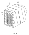
- a tape machine (not shown) applies one or more layers of conductive tape 130 to stator bars 104. As shown in Figure 3, in one embodiment, tape machine applies two separate half-lapped layers of conductive tape 130, around stator bars 104 onto insulation 128. Because each layer is half-lapped, the final stator bar has four layers (or thicknesses) of tape per side, or eight total layers of conductive tape 130 as the total build for stator bar 104. In alternative embodiments, conductive tape 130 is applied side by side, in that each layer of tape butts against another layer of tape. Those skilled in the art and guided by the teachings provided herein know that many arrangements and thicknesses of tape 130 may be used in order to achieve the desired resistivity.
- one half-lapped layer of conductive tape 130 which has two thicknesses of conductive tape 130, has a total thickness from about 0.008 inch to about 0.011 inch. In this embodiment, the thickness of conductive tape 130 is from about .004 inch to about .006 inch.
- the total thickness of the layer(s) of conductive tape 130 is substantial enough so as to allow an operator or machine to manipulate the size dimensions of the final stator bar product by removing a portion of conductive tape 130.
- the total thickness of the layer(s) of conductive tape 130 is about 0.035 to about 0.045 inch. More specifically, in one embodiment, the total thickness of the layer(s) of conductive tape 130 is about 0.040 to about 0.045 inch.
- two half-lapped layers on one side of stator bar 104 have a total thickness from about 0.016 inch to about 0.022 inch.
- the total build i.e., the total thickness of conductive tape 130 used on both sides
- the width of conductive tape 130 is amenable for applying conductive tape 130 to insulation 128. In one embodiment, the width of conductive tape 130 is amenable for applying conductive tape 130 half-lapped onto insulation 128. In one embodiment, the width of conductive tape 130 is approximately one inch.
- Stator bar 104 with insulation 128 and conductive tape 130 is then cured in an autoclave by known processes. In one embodiment, the duration of curing is approximately 20 hours. After curing, stator bar 104 is stripped of sacrifice material.
- the curing process alters the resistivity range of conductive tape 130 and, consequently, stator bar 104.
- composition of conductive tape 130 and the curing process can be altered to reach a final desired resistivity.
- the desired resistivity range of the outer surface of stator bar 104 must not be too low so that a current and voltage is induced in the armor by the magnetic field. But the desired resistivity range must not be so high that it prevents discharge of the gas at the surface of stator bar 104.
- the acceptable resistance range is a function of the distance between a grounding point of conductive tape 130 and the core laminations.
- the desired surface resistivity range is from about 500 to about 100,000 ohms/square. In another embodiment, the desired resistivity range is from about 1,500 to about 100,000 ohms/square.
- conductive tape 130 can be removed and known glass tape processes discussed above can be used.
- stator bar 104 After curing, stator bar 104 is inspected for proper size dimensions, the existence of any flaws, and the armor resistivity is tested.
- insulation 128 with conductive tape 130 By curing insulation 128 with conductive tape 130, unlike previously known processes, a significant amount of time can be saved and costs reduced.
- stator bars Exemplary embodiments of methods and stator bars are described and/or illustrated herein in detail.
- the methods and stator bars are not limited to the specific embodiments described herein, but rather, components of each stator bar and steps of each method may be utilized independently and separately from other components and steps described herein.
- Each stator bar component and method step can also be used in combination with other stator bar components and/or method steps.
Landscapes
- Engineering & Computer Science (AREA)
- Power Engineering (AREA)
- Manufacturing & Machinery (AREA)
- Manufacture Of Motors, Generators (AREA)
- Insulation, Fastening Of Motor, Generator Windings (AREA)
Applications Claiming Priority (1)
| Application Number | Priority Date | Filing Date | Title |
|---|---|---|---|
| US11/462,613 US7634852B2 (en) | 2006-08-04 | 2006-08-04 | Method for manufacturing liquid-cooled stator bars |
Publications (1)
| Publication Number | Publication Date |
|---|---|
| EP1885044A2 true EP1885044A2 (de) | 2008-02-06 |
Family
ID=38686698
Family Applications (1)
| Application Number | Title | Priority Date | Filing Date |
|---|---|---|---|
| EP07113405A Withdrawn EP1885044A2 (de) | 2006-08-04 | 2007-07-30 | Flüssigkeitsgekühlte Statorstäbe und Herstellungsverfahren dafür |
Country Status (2)
| Country | Link |
|---|---|
| US (1) | US7634852B2 (de) |
| EP (1) | EP1885044A2 (de) |
Cited By (1)
| Publication number | Priority date | Publication date | Assignee | Title |
|---|---|---|---|---|
| CN110601411A (zh) * | 2019-09-19 | 2019-12-20 | 中车株洲电机有限公司 | 一种定子槽部组件及其制造方法 |
Families Citing this family (8)
| Publication number | Priority date | Publication date | Assignee | Title |
|---|---|---|---|---|
| DE602006015937D1 (de) * | 2006-06-21 | 2010-09-16 | Abb Technology Ltd | Vorrichtung zur elektrischen Feldsteuerung |
| EP2475076A1 (de) * | 2011-01-05 | 2012-07-11 | Alstom Technology Ltd | Verfahren zur Herstellung eines Stators und eines Statorstabs, Stator und Statorstab |
| US11979070B2 (en) * | 2012-02-24 | 2024-05-07 | Integrated Power Services LLC | Electrical machine coil insulation system and method |
| US9293972B2 (en) * | 2013-12-06 | 2016-03-22 | General Electric Company | Apparatus for forming insulation for electrical components |
| CN104124890A (zh) * | 2014-07-05 | 2014-10-29 | 南通长江电器实业有限公司 | 一种航空用超声波电机定子的制造方法 |
| US10992201B2 (en) | 2017-08-07 | 2021-04-27 | General Electric Company | Electrical propulsion system with corona suppression on a vehicle |
| KR20190138483A (ko) | 2018-06-05 | 2019-12-13 | 두산중공업 주식회사 | 고정자 코일 구조와 이를 포함하는 고정자 및 발전기 |
| US11791684B2 (en) | 2020-07-02 | 2023-10-17 | Ge Aviation Systems Llc | Method and system for electrically insulating portions of an electric machine |
Family Cites Families (18)
| Publication number | Priority date | Publication date | Assignee | Title |
|---|---|---|---|---|
| DE2130201A1 (de) * | 1971-06-18 | 1972-12-21 | Kraftwerk Union Ag | Anordnung zur Fixierung der Staenderwicklungsstaebe elektrischer Maschinen,insbesondere bei Turbogeneratoren |
| US3930915A (en) * | 1973-04-17 | 1976-01-06 | Westinghouse Electric Corporation | Method of making an electrical article |
| US5066881A (en) | 1984-08-23 | 1991-11-19 | General Electric Company | Semi-conducting layer for insulated electrical conductors |
| US4853565A (en) | 1984-08-23 | 1989-08-01 | General Electric Company | Semi-conducting layer for insulated electrical conductors |
| US5175396A (en) | 1990-12-14 | 1992-12-29 | Westinghouse Electric Corp. | Low-electric stress insulating wall for high voltage coils having roebeled strands |
| US5723920A (en) | 1994-10-12 | 1998-03-03 | General Electric Company | Stator bars internally graded with conductive binder tape |
| US5618891A (en) | 1995-03-29 | 1997-04-08 | General Electric Co. | Solventless resin composition having minimal reactivity at room temperature |
| US5973269A (en) | 1996-04-16 | 1999-10-26 | General Electric Canada Inc. | Multi-layer insulation for winding elements of dynamoelectric machines (D.E.M.s) |
| US6359232B1 (en) | 1996-12-19 | 2002-03-19 | General Electric Company | Electrical insulating material and stator bar formed therewith |
| JPH1189130A (ja) * | 1997-09-08 | 1999-03-30 | Minebea Co Ltd | モータ構造 |
| DE69739076D1 (de) * | 1997-12-18 | 2008-12-11 | Mitsubishi Electric Corp | Rotierende elektrische Maschine |
| US6043582A (en) | 1998-08-19 | 2000-03-28 | General Electric Co. | Stable conductive material for high voltage armature bars |
| US6190775B1 (en) * | 2000-02-24 | 2001-02-20 | Siemens Westinghouse Power Corporation | Enhanced dielectric strength mica tapes |
| US6498415B1 (en) | 2000-09-06 | 2002-12-24 | Siemens Westinghouse Power Corporation | High voltage stator coil having low loss insulator and electrode covering and method therefor |
| US6420812B1 (en) | 2000-09-07 | 2002-07-16 | Siemens Westinghouse Power Corporation | High voltage generator stator coils and methods of forming same |
| ES2319392T3 (es) * | 2001-04-20 | 2009-05-07 | Converteam Ltd | Refrigeracion de un arrollamiento de entrehierro de maquinas electricas. |
| JP3576119B2 (ja) * | 2001-04-27 | 2004-10-13 | 株式会社東芝 | 回転電機のコイル及びこのコイルの絶縁に用いられるマイカーテープ |
| US7135639B2 (en) * | 2003-09-05 | 2006-11-14 | Siemens Power Generation, Inc. | Integral slip layer for insulating tape |
-
2006
- 2006-08-04 US US11/462,613 patent/US7634852B2/en not_active Expired - Fee Related
-
2007
- 2007-07-30 EP EP07113405A patent/EP1885044A2/de not_active Withdrawn
Cited By (1)
| Publication number | Priority date | Publication date | Assignee | Title |
|---|---|---|---|---|
| CN110601411A (zh) * | 2019-09-19 | 2019-12-20 | 中车株洲电机有限公司 | 一种定子槽部组件及其制造方法 |
Also Published As
| Publication number | Publication date |
|---|---|
| US7634852B2 (en) | 2009-12-22 |
| US20080029291A1 (en) | 2008-02-07 |
Similar Documents
| Publication | Publication Date | Title |
|---|---|---|
| EP1885044A2 (de) | Flüssigkeitsgekühlte Statorstäbe und Herstellungsverfahren dafür | |
| KR100532255B1 (ko) | 권선 소자 및 접지벽 절연체 | |
| US20130221790A1 (en) | Electrical machine coil insulation system and method | |
| US3990029A (en) | Insulated windings provided with a mould releasing material | |
| US7705243B2 (en) | Electrical-discharge-inhibiting conformable layer for use in inner-cooled coils | |
| US11605994B2 (en) | Winding insulation system | |
| US20140083592A1 (en) | Method of producing an electrical insulation system for an electric machine | |
| KR100643499B1 (ko) | 고전압 고정자 코일의 뢰벨 충전재내에서의 부분 방전을감소시키는 방법 | |
| US20050072592A1 (en) | Stator bar with exruded groundwall insulation | |
| EP2810358B1 (de) | Hochspannungsstatorspule mit einer kippfunktion mit reduziertem stromverbrauch | |
| US6677848B1 (en) | High-voltage winding including double-sided insulating tape and associated methods | |
| Emery | The application of conductive and stress grading tapes to vacuum pressure impregnated, high voltage stator coils | |
| Allison | Understanding the need for anti-corona materials in high voltage rotating machines | |
| US2318074A (en) | Corona elimination in generator end windings | |
| Brütsch et al. | Insulating systems for high voltage rotating machines and reliability considerations | |
| US20140300241A1 (en) | Electrical machine medium voltage coil insulation systems and methods | |
| US20040182596A1 (en) | Method and apparatus for insulating magnet wire | |
| Gegenava et al. | Corona in high voltage rotating machines stator. Causes, repair and prognosis | |
| JP6014833B2 (ja) | 回転電機のコイル | |
| US7223920B2 (en) | Through-bolt insulating boot | |
| WO2018206222A1 (en) | Insultated wire of a stator winding comprising grounding by conducting layer | |
| EP2405558A1 (de) | Statorstab | |
| Chapman et al. | Suppression of partial discharges in high-voltage rotating machines | |
| US7238404B2 (en) | Thin sheet mica wedges with semi-conducting properties | |
| Stranges et al. | A comparative evaluation of various conducting slot armour materials |
Legal Events
| Date | Code | Title | Description |
|---|---|---|---|
| PUAI | Public reference made under article 153(3) epc to a published international application that has entered the european phase |
Free format text: ORIGINAL CODE: 0009012 |
|
| AK | Designated contracting states |
Kind code of ref document: A2 Designated state(s): AT BE BG CH CY CZ DE DK EE ES FI FR GB GR HU IE IS IT LI LT LU LV MC MT NL PL PT RO SE SI SK TR |
|
| AX | Request for extension of the european patent |
Extension state: AL BA HR MK YU |
|
| STAA | Information on the status of an ep patent application or granted ep patent |
Free format text: STATUS: THE APPLICATION IS DEEMED TO BE WITHDRAWN |
|
| 18D | Application deemed to be withdrawn |
Effective date: 20110201 |