EP1885034A1 - Fluid-dispensing reservoir for large-diameter slip rings - Google Patents
Fluid-dispensing reservoir for large-diameter slip rings Download PDFInfo
- Publication number
- EP1885034A1 EP1885034A1 EP20070252725 EP07252725A EP1885034A1 EP 1885034 A1 EP1885034 A1 EP 1885034A1 EP 20070252725 EP20070252725 EP 20070252725 EP 07252725 A EP07252725 A EP 07252725A EP 1885034 A1 EP1885034 A1 EP 1885034A1
- Authority
- EP
- European Patent Office
- Prior art keywords
- tube
- brush
- improvement
- fluid
- fibers
- Prior art date
- Legal status (The legal status is an assumption and is not a legal conclusion. Google has not performed a legal analysis and makes no representation as to the accuracy of the status listed.)
- Granted
Links
- 239000012530 fluid Substances 0.000 claims abstract description 30
- 239000000835 fiber Substances 0.000 claims abstract description 28
- 230000006872 improvement Effects 0.000 claims abstract description 16
- 239000000314 lubricant Substances 0.000 claims abstract description 13
- 239000004020 conductor Substances 0.000 claims abstract description 6
- 239000000654 additive Substances 0.000 claims abstract description 5
- 230000000996 additive effect Effects 0.000 claims abstract description 5
- 238000005260 corrosion Methods 0.000 claims abstract description 5
- 239000003112 inhibitor Substances 0.000 claims abstract description 5
- 230000007797 corrosion Effects 0.000 claims abstract description 4
- 239000000463 material Substances 0.000 claims description 6
- 239000011148 porous material Substances 0.000 claims description 6
- 239000004677 Nylon Substances 0.000 claims description 4
- 229920001778 nylon Polymers 0.000 claims description 4
- OKTJSMMVPCPJKN-UHFFFAOYSA-N Carbon Chemical compound [C] OKTJSMMVPCPJKN-UHFFFAOYSA-N 0.000 description 5
- 239000010408 film Substances 0.000 description 5
- 229910002804 graphite Inorganic materials 0.000 description 5
- 239000010439 graphite Substances 0.000 description 5
- 238000005461 lubrication Methods 0.000 description 5
- 238000012986 modification Methods 0.000 description 4
- 230000004048 modification Effects 0.000 description 4
- 239000000126 substance Substances 0.000 description 4
- 238000000034 method Methods 0.000 description 3
- 230000008569 process Effects 0.000 description 3
- 239000000919 ceramic Substances 0.000 description 2
- 239000002131 composite material Substances 0.000 description 2
- 239000004744 fabric Substances 0.000 description 2
- 238000010438 heat treatment Methods 0.000 description 2
- 229910001092 metal group alloy Inorganic materials 0.000 description 2
- 235000013824 polyphenols Nutrition 0.000 description 2
- 239000000843 powder Substances 0.000 description 2
- 229910000906 Bronze Inorganic materials 0.000 description 1
- 239000010974 bronze Substances 0.000 description 1
- 239000000356 contaminant Substances 0.000 description 1
- KUNSUQLRTQLHQQ-UHFFFAOYSA-N copper tin Chemical compound [Cu].[Sn] KUNSUQLRTQLHQQ-UHFFFAOYSA-N 0.000 description 1
- 239000000428 dust Substances 0.000 description 1
- 239000010687 lubricating oil Substances 0.000 description 1
- 230000007246 mechanism Effects 0.000 description 1
- 239000002184 metal Substances 0.000 description 1
- ISWSIDIOOBJBQZ-UHFFFAOYSA-N phenol group Chemical group C1(=CC=CC=C1)O ISWSIDIOOBJBQZ-UHFFFAOYSA-N 0.000 description 1
- 239000011343 solid material Substances 0.000 description 1
- 239000010409 thin film Substances 0.000 description 1
Images
Classifications
-
- H—ELECTRICITY
- H01—ELECTRIC ELEMENTS
- H01R—ELECTRICALLY-CONDUCTIVE CONNECTIONS; STRUCTURAL ASSOCIATIONS OF A PLURALITY OF MUTUALLY-INSULATED ELECTRICAL CONNECTING ELEMENTS; COUPLING DEVICES; CURRENT COLLECTORS
- H01R39/00—Rotary current collectors, distributors or interrupters
- H01R39/02—Details for dynamo electric machines
- H01R39/56—Devices for lubricating or polishing slip-rings or commutators during operation of the collector
-
- H—ELECTRICITY
- H01—ELECTRIC ELEMENTS
- H01R—ELECTRICALLY-CONDUCTIVE CONNECTIONS; STRUCTURAL ASSOCIATIONS OF A PLURALITY OF MUTUALLY-INSULATED ELECTRICAL CONNECTING ELEMENTS; COUPLING DEVICES; CURRENT COLLECTORS
- H01R39/00—Rotary current collectors, distributors or interrupters
- H01R39/02—Details for dynamo electric machines
- H01R39/18—Contacts for co-operation with commutator or slip-ring, e.g. contact brush
- H01R39/24—Laminated contacts; Wire contacts, e.g. metallic brush, carbon fibres
-
- H—ELECTRICITY
- H01—ELECTRIC ELEMENTS
- H01R—ELECTRICALLY-CONDUCTIVE CONNECTIONS; STRUCTURAL ASSOCIATIONS OF A PLURALITY OF MUTUALLY-INSULATED ELECTRICAL CONNECTING ELEMENTS; COUPLING DEVICES; CURRENT COLLECTORS
- H01R39/00—Rotary current collectors, distributors or interrupters
- H01R39/02—Details for dynamo electric machines
- H01R39/38—Brush holders
- H01R39/381—Brush holders characterised by the application of pressure to brush
Definitions
- the present invention relates generally to slip rings for communicating electrical power and/or signal(s) between a rotor and stator, and, more particularly, to improvements in large-diameter slip rings that allow higher current densities, longer life, and higher rotor surface speeds to be achieved at lower costs then with conventional slip ring technology.
- Electrical slip rings are used to transfer electrical power and/or signals between a rotor and a stator. These devices are used in many different military and commercial applications, such as solar array drive mechanisms, aircraft and missile guidance platforms, undersea robots, CATSCAN systems, and the like. In some of these applications, slip rings are used in conjunction with other rotary components, such as torque motors, resolvers and encoders. Electrical slip rings must be designed to be located either on the platform axis of rotation, or be designed with an open bore which locates the electrical contacts off-axis. Hence, the designations "on-axis" and “off-axis” slip rings, respectively.
- the diameter of slip ring rotors may range from a fraction of an inch to multiple feet, and the angular speed may vary from one revolution per day to as much as 20,000 revolutions per minute.
- the electrical contacts between the rotor and stator must: (1) transfer power and/or signal(s) without interruption at high surface speeds, (2) have long wear life, (3) maintain low electrical noise, and (4) be of a physical size that allows multiple circuits to be packaged in a minimum volume.
- the electrical contacts must be designed to carry about 100-200 amps (with surges of hundreds of amps), operate at surface speeds on the order of 500 inches per second, last for 100 million revolutions, and occupy a minimal volume within the gantry.
- the brush force In order to meet the 100 million revolution requirement for a device that is about six feet in diameter, the brush force must be low to minimize frictional heating and to maintain a large number of contact points between brush and ring to achieve the required current density.
- a rotor and stator Four types of electrical contacts between a rotor and stator include: (1) a composite solid material brush on a cantilevered spring, (2) a monofilament metal alloy brush that tangentially engages the rotor, (3) a fiber brush having a plurality of individual fibers, with the bundle tangentially engaging the rotor, and (4) a tip-of-fiber contact between the brush and rotor.
- the contact force, surface speeds and type of lubrication for each contact type is summarized in Table I. Table I also shows the types of lubricants heretofore typically required to reduce the contact frictional heating if the brush force is above one gram.
- the tribological properties of electrical contacts and the right choice of lubricant to meet the requirements of the application are extremely important. For example, if the contacts are to be used in a space application, then the lubricant must meet all of the requirements of a ground-based application, and have a low vapor pressure. If the contacts have a long life requirement, then dust, wear debris and other contaminants may accumulate in the contact zone and create problems with life and signal transfer. However, if the electrical contact members can be brought together with a force of about one gram or less, then the lubricant and the associated complications are eliminated.
- the added fluid may be a lubricant, or a chemical vapor emitter, or an anti-corrosion inhibitor, or a material having a high dielectric strength to retard electrical arcing.
- the principal object of the invention is to provide a fiber-on-tips brush with a fluid-dispensing reservoir for selectively dispensing a fluid, particularly during the brush run-in process.
- the present invention broadly provides an improvement in a slip ring (20) adapted to provide electrical contact between a stator (21) and a rotor (22).
- the improvement broadly comprises: a current-carrying conductor (23) mounted on the stator; a brush tube (24) mounted on the conductor; a fiber bundle composed of a number of individual fibers (26), the upper marginal end portions of the fibers being received in the brush tube, a portion of the brush tube being crimped or swaged to hold the upper marginal end portions of the fibers therein, the lower ends of the fibers in the bundle extending beyond the brush tube and being adapted to engage the rotor; a collimator tube (25) surrounding a portion of the brush tube and extending therebeyond, the lower end of the collimator tube being adapted to limit lateral movement of the lower marginal end portions of the fibers in the bundle when the rotor rotates relative to the stator; and a fluid reservoir (28) mounted on the collimator tube.
- the reservoir may be mounted on the inside of the collimator tube, and may be concentric with the brush tube.
- the length of overlap of the collimator and brush tubes may be adjustable.
- the reservoir may be formed of a porous material, such as nylon, a suitable cloth-filled phenolic, a porous graphite, a ceramic, a bearing bronze, etc.
- the reservoir may contain a fluid, and be arranged to dispense the fluid over a period of time.
- the fluid may be a lubricant, a corrosion inhibitor, a fluid having a high dielectric strength additive, or some other fluid.
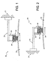
- Fig. 1 is a schematic view of a first form of fiber-on-tips brush, incorporating a fluid reservoir within a fixed collimator, this view showing the rotor as rotating in a counter-clockwise direction.
- Fig. 2 is a schematic vertical sectional view of a second form of improved fiber-on-tips brush, this view showing the fluid reservoir as being located within a collimator which is adjustably mounted on the brush tube, this view showing the rotor as rotating in a clockwise direction.
- the terms “horizontal”, “vertical”, “left”, “right”, “up” and “down”, as well as adjectival and adverbial derivatives thereof simply refer to the orientation of the illustrated structure as the particular drawing figure faces the reader.
- the terms “inwardly” and “outwardly” generally refer to the orientation of a surface relative to its axis of elongation, or axis of rotation, as appropriate.
- the present invention broadly provides an improved slip ring having a fluid-dispensing reservoir.
- an improved brush is shown as being mounted on a stator 21, to engage a rotor 22, which is depicted as rotating in the counter-clockwise direction. More particularly, the improved brush has a arm 23 extending outwardly from the stator as a cantilever, and has a brush tube 24 depending from the distal of the arm. A collimator 25 extends downwardly from the brush tube 24. A fiber bundle, comprising a plurality of individual fibers, severally indicated at 26, is clamped, crimped or otherwise secured in the brush tube in the manner disclosed in said Patent Application No. 10/871,090. In Fig. 1, the brush tube 24 and collimator 25 are formed of a single tubular piece, suitably bent or otherwise deformed to the shape shown.
- the improvement comprises an annular fluid reservoir, generally indicated at 28, that is mounted on the collimator tube beneath the brush tube, so as to surround an intermediate portion of the individual fibers.
- This fluid reservoir may be formed of a suitable porous material, such as nylon.
- a suitable porous material such as nylon.
- One possible form of such apparatus is sold under the trademark "Nylasint” by Polytron Kunststofftechnik GmbH & Co., KG, An der Zinkdazzling 17, 51469 Bergisch Gladbach, Germany.
- "Nylasint” is generically referred to as a pressed or centered article, both porous and nonporous, formed from filled or unfilled synthetic polymeric powders, in the form of synthetic polymeric powders.
- This porous material may be impregnated with a suitable fluid, such as a lubricant, a corrosion inhibitor, a fluid having a high dielectric strength additive to prevent arcing, or the like.
- the size and shape of the fluid reservoir is considered to be a matter of design choice. In other words, the size and shape of the reservoir may be adjusted so as to dispense the fluid during the initial run-in period of the brush, or a longer period, as desired. If a lubricant is used, this can aid in the initial brush run-in process, and allows the brush face to wear-in or become contoured to the shape of the rotor.
- Fig. 2 is a view of an alternative arrangement.
- the improved brush is generally indicated at 30.
- Brush 30 appears to be substantially a mirror image of brush 20, as discussed above.
- Brush 30 is shown as being mounted on a stator 31 and to engage a rotor 32.
- the rotor is depicted as rotating in a clockwise direction.
- the brush includes an arm 33 extending rightwardly from the stator.
- a brush tube 34 and a collimator 35 are supported on the rightward or distal marginal end portion of the arm.
- the brush tube 24 and collimator 25 were formed integrally in Fig. 1, in Fig. 2, they are formed as separate members, such that the collimator tube overlaps the lower marginal end of the brush tube.
- the extent of overlap of the collimator tube over the brush tube may be selectively adjusted in Fig. 2.
- a fiber bundle, containing a plurality of individual fibers, severally indicated at 36, is mounted in the brush tube.
- An annular reservoir 38 is mounted on the lower marginal end portion of the collimator tube.
- reservoir 38 may be a porous material, such as Nylasint®, that is impregnated with a liquid lubricant.
- it may be impregnated with a suitable chemical so that it will emit a chemical vapor, will dispense a high dielectric strength additive to help prevent electrical arcing, or the like.
- the fluid reservoir is shown as being an annular cylindrical ring having a substantially rectangular cross-section, the reservoir could be formed in other shapes and configurations as well. While it is presented preferred that the reservoir be formed of a porous material, such as a porous nylon, the reservoir may be formed of other materials as well.
- the service fluid may be a lubricant, a source of chemical vapor, a fluid having a high dielectric strength to retard electrical arcing, or the like.
- the reservoir may be impregnated with other types of fluids as well.
- the size of the slip ring should not be regarded as being a limitation on the scope of the appended claims.
Landscapes
- Motor Or Generator Current Collectors (AREA)
Abstract
Description
- The present application is a continuation-in-part of pending
U.S. Patent Application Serial No. 10/871,090, filed June 18, 2004 - The present invention relates generally to slip rings for communicating electrical power and/or signal(s) between a rotor and stator, and, more particularly, to improvements in large-diameter slip rings that allow higher current densities, longer life, and higher rotor surface speeds to be achieved at lower costs then with conventional slip ring technology.
- Electrical slip rings are used to transfer electrical power and/or signals between a rotor and a stator. These devices are used in many different military and commercial applications, such as solar array drive mechanisms, aircraft and missile guidance platforms, undersea robots, CATSCAN systems, and the like. In some of these applications, slip rings are used in conjunction with other rotary components, such as torque motors, resolvers and encoders. Electrical slip rings must be designed to be located either on the platform axis of rotation, or be designed with an open bore which locates the electrical contacts off-axis. Hence, the designations "on-axis" and "off-axis" slip rings, respectively. The diameter of slip ring rotors may range from a fraction of an inch to multiple feet, and the angular speed may vary from one revolution per day to as much as 20,000 revolutions per minute. In all of these applications, the electrical contacts between the rotor and stator must: (1) transfer power and/or signal(s) without interruption at high surface speeds, (2) have long wear life, (3) maintain low electrical noise, and (4) be of a physical size that allows multiple circuits to be packaged in a minimum volume.
- The most efficient management of the electrical and mechanical contact physics allows the most demanding requirements to be met. For example, if the application is an off-axis slip ring that allows the x-ray tube in a CATSCAN gantry to rotate about the patient's body, the electrical contacts must be designed to carry about 100-200 amps (with surges of hundreds of amps), operate at surface speeds on the order of 500 inches per second, last for 100 million revolutions, and occupy a minimal volume within the gantry. In order to meet the 100 million revolution requirement for a device that is about six feet in diameter, the brush force must be low to minimize frictional heating and to maintain a large number of contact points between brush and ring to achieve the required current density.
- Four types of electrical contacts between a rotor and stator include: (1) a composite solid material brush on a cantilevered spring, (2) a monofilament metal alloy brush that tangentially engages the rotor, (3) a fiber brush having a plurality of individual fibers, with the bundle tangentially engaging the rotor, and (4) a tip-of-fiber contact between the brush and rotor. The contact force, surface speeds and type of lubrication for each contact type is summarized in Table I. Table I also shows the types of lubricants heretofore typically required to reduce the contact frictional heating if the brush force is above one gram.
Table I Contact Type Contact Force Surface Speeds Type of Lubrication composite brush 0.4 kg/cm2 700 in/sec sacrificial graphite film* monofilament metal alloy 3-20 grams 12 in/sec boundary lubrication** tangential fiber brush 1-3 grams 200 in/sec adventitious*** fiber-on-tip 0.1-1 grams 1200 in/sec adventitious*** * With a sacrificial graphite film, the brush and ring interface is lubricated by a film of graphite that is transferred from the brush to the ring. Material that is worn away is replaced by graphite from the brush.
** With boundary lubrication, a boundary lubricant film supports a portion of the load between the contact members. The points of metal contact support the remaining load between the contact members, and provide the current-carrying capability.
*** With adventitious films, very thin films of materials that are capable of reducing the coefficient of friction between the contact members under light loads. - The tribological properties of electrical contacts and the right choice of lubricant to meet the requirements of the application are extremely important. For example, if the contacts are to be used in a space application, then the lubricant must meet all of the requirements of a ground-based application, and have a low vapor pressure. If the contacts have a long life requirement, then dust, wear debris and other contaminants may accumulate in the contact zone and create problems with life and signal transfer. However, if the electrical contact members can be brought together with a force of about one gram or less, then the lubricant and the associated complications are eliminated.
- For several years, fiber brushes with a tangential orientation to the ring have been successfully used to meet high surface speeds without the use of a lubricant.
- Under certain conditions, it may be desirable to provide lubrication during the initial brush run-in process. Moreover, the added fluid may be a lubricant, or a chemical vapor emitter, or an anti-corrosion inhibitor, or a material having a high dielectric strength to retard electrical arcing.
- Accordingly, the principal object of the invention is to provide a fiber-on-tips brush with a fluid-dispensing reservoir for selectively dispensing a fluid, particularly during the brush run-in process.
- With parenthetical reference to the corresponding parts, portions or surfaces of the disclosed embodiment, merely for purposes of illustration, and not by way of limitation, the present invention broadly provides an improvement in a slip ring (20) adapted to provide electrical contact between a stator (21) and a rotor (22). The improvement broadly comprises: a current-carrying conductor (23) mounted on the stator; a brush tube (24) mounted on the conductor; a fiber bundle composed of a number of individual fibers (26), the upper marginal end portions of the fibers being received in the brush tube, a portion of the brush tube being crimped or swaged to hold the upper marginal end portions of the fibers therein, the lower ends of the fibers in the bundle extending beyond the brush tube and being adapted to engage the rotor; a collimator tube (25) surrounding a portion of the brush tube and extending therebeyond, the lower end of the collimator tube being adapted to limit lateral movement of the lower marginal end portions of the fibers in the bundle when the rotor rotates relative to the stator; and a fluid reservoir (28) mounted on the collimator tube.
- The reservoir may be mounted on the inside of the collimator tube, and may be concentric with the brush tube. The length of overlap of the collimator and brush tubes may be adjustable.
- The reservoir may be formed of a porous material, such as nylon, a suitable cloth-filled phenolic, a porous graphite, a ceramic, a bearing bronze, etc. The reservoir may contain a fluid, and be arranged to dispense the fluid over a period of time. The fluid may be a lubricant, a corrosion inhibitor, a fluid having a high dielectric strength additive, or some other fluid.
- These and other objects and advantages will become apparent from the foregoing and ongoing written specification, the drawings, and the appended claims.
- Fig. 1 is a schematic view of a first form of fiber-on-tips brush, incorporating a fluid reservoir within a fixed collimator, this view showing the rotor as rotating in a counter-clockwise direction.
- Fig. 2 is a schematic vertical sectional view of a second form of improved fiber-on-tips brush, this view showing the fluid reservoir as being located within a collimator which is adjustably mounted on the brush tube, this view showing the rotor as rotating in a clockwise direction.
- At the outset, it should be clearly understood that like reference numerals are intended to identify the same structural elements, portions or surfaces consistently throughout the several drawing figures, as such elements, portions or surfaces may be further described or explained by the entire written specification, of which this detailed description is an integral part. Unless otherwise indicated, the drawings are intended to be read (e.g., cross-hatching, arrangement of parts, proportion, degree, etc.) together with the specification, and are to be considered a portion of the entire written description of this invention. As used in the following description, the terms "horizontal", "vertical", "left", "right", "up" and "down", as well as adjectival and adverbial derivatives thereof (e.g., "horizontally", "rightwardly", "upwardly", etc.), simply refer to the orientation of the illustrated structure as the particular drawing figure faces the reader. Similarly, the terms "inwardly" and "outwardly" generally refer to the orientation of a surface relative to its axis of elongation, or axis of rotation, as appropriate.
- Referring now to the drawings, the present invention broadly provides an improved slip ring having a fluid-dispensing reservoir.
- This general type of slip ring is disclosed in pending
U.S. Patent Application Serial No. 10/871,090, filed on June 18, 2004 - As best shown in Fig. 1, an improved brush, generally indicated at 20, is shown as being mounted on a
stator 21, to engage arotor 22, which is depicted as rotating in the counter-clockwise direction. More particularly, the improved brush has aarm 23 extending outwardly from the stator as a cantilever, and has abrush tube 24 depending from the distal of the arm. Acollimator 25 extends downwardly from thebrush tube 24. A fiber bundle, comprising a plurality of individual fibers, severally indicated at 26, is clamped, crimped or otherwise secured in the brush tube in the manner disclosed in said Patent Application No. 10/871,090. In Fig. 1, thebrush tube 24 andcollimator 25 are formed of a single tubular piece, suitably bent or otherwise deformed to the shape shown. - The improvement comprises an annular fluid reservoir, generally indicated at 28, that is mounted on the collimator tube beneath the brush tube, so as to surround an intermediate portion of the individual fibers.
- This fluid reservoir may be formed of a suitable porous material, such as nylon. One possible form of such apparatus is sold under the trademark "Nylasint" by Polytron Kunststofftechnik GmbH & Co., KG, An der Zinkhütte 17, 51469 Bergisch Gladbach, Germany. "Nylasint" is generically referred to as a pressed or centered article, both porous and nonporous, formed from filled or unfilled synthetic polymeric powders, in the form of synthetic polymeric powders. This porous material may be impregnated with a suitable fluid, such as a lubricant, a corrosion inhibitor, a fluid having a high dielectric strength additive to prevent arcing, or the like. Other types of materials, including (but not limited to) cloth-filled phenolics, porous graphites, ceramics and bearing bronzes, etc., might be substituted for "Nylansint". The size and shape of the fluid reservoir is considered to be a matter of design choice. In other words, the size and shape of the reservoir may be adjusted so as to dispense the fluid during the initial run-in period of the brush, or a longer period, as desired. If a lubricant is used, this can aid in the initial brush run-in process, and allows the brush face to wear-in or become contoured to the shape of the rotor.
- Fig. 2 is a view of an alternative arrangement. In this form, the improved brush is generally indicated at 30.
Brush 30 appears to be substantially a mirror image of brush 20, as discussed above.Brush 30 is shown as being mounted on astator 31 and to engage arotor 32. In Fig. 2, the rotor is depicted as rotating in a clockwise direction. The brush includes anarm 33 extending rightwardly from the stator. Abrush tube 34 and acollimator 35 are supported on the rightward or distal marginal end portion of the arm. However, whereas thebrush tube 24 andcollimator 25 were formed integrally in Fig. 1, in Fig. 2, they are formed as separate members, such that the collimator tube overlaps the lower marginal end of the brush tube. More particularly, the extent of overlap of the collimator tube over the brush tube may be selectively adjusted in Fig. 2. A fiber bundle, containing a plurality of individual fibers, severally indicated at 36, is mounted in the brush tube. Anannular reservoir 38 is mounted on the lower marginal end portion of the collimator tube. Here again, the particular size, shape and configuration of the reservoir may be varied to suit the particular application and need. As with the first form,reservoir 38 may be a porous material, such as Nylasint®, that is impregnated with a liquid lubricant. Alternatively, it may be impregnated with a suitable chemical so that it will emit a chemical vapor, will dispense a high dielectric strength additive to help prevent electrical arcing, or the like. - The present invention expressly contemplated that many modifications and changes may be made. For example, where as the fluid reservoir is shown as being an annular cylindrical ring having a substantially rectangular cross-section, the reservoir could be formed in other shapes and configurations as well. While it is presented preferred that the reservoir be formed of a porous material, such as a porous nylon, the reservoir may be formed of other materials as well. The service fluid may be a lubricant, a source of chemical vapor, a fluid having a high dielectric strength to retard electrical arcing, or the like. The reservoir may be impregnated with other types of fluids as well. The size of the slip ring should not be regarded as being a limitation on the scope of the appended claims.
- Therefore, while the present invention has been shown and described, and several modifications thereof discussed, persons skilled in this art will readily appreciate that various additional changes and modifications may be made, without departing from the spirit of the invention, as defined and differentiated by the following claims.
Claims (10)
- In a slip ring adapted to provide electrical contact between a stator and a rotor, the improvement comprising:a current-carrying conductor mounted on said stator;a brush tube mounted on said conductor;a fiber bundle composed of a number of individual fibers, the upper marginal end portions of said fibers being received in said brush tube, a portion of said brush tube being crimped or swaged to hold the upper marginal end portions of said fibers therein, the lower ends of the fibers in said bundle extending beyond said brush tube and being adapted to engage said rotor;a collimator tube surrounding a portion of said brush tube and extending therebeyond, the lower end of said collimator tube being adapted to limit lateral movement of the lower marginal end portions of said fibers in said bundle when said rotor rotates relative to said stator; anda fluid reservoir mounted on said collimator tube.
- The improvement as set forth in claim 1 wherein said reservoir is mounted on the inside of said collimator tube.
- The improvement as set forth in claim 2 wherein said collimator tube is concentric with said brush tube.
- The improvement as set forth in claim 3 wherein the length of overlap of said collimator and brush tubes is adjustable.
- The improvement as set forth in claim 1 wherein said reservoir is formed of a porous material.
- The improvement as set forth in claim 5 wherein said material is nylon.
- The improvement as set forth in claim 1 wherein said reservoir contains a fluid, and wherein said reservoir is arranged to dispense said fluid over a period of time.
- The improvement as set forth in claim 7 wherein said fluid includes a lubricant.
- The improvement as set forth in claim 7 wherein said fluid includes a corrosion inhibitor.
- The improvement as set forth in claim7 wherein said fluid includes a high dielectric strength additive.
Applications Claiming Priority (1)
| Application Number | Priority Date | Filing Date | Title |
|---|---|---|---|
| US11/499,289 US7423359B2 (en) | 2004-06-18 | 2006-08-04 | Fluid-dispensing reservoir for large-diameter slip rings |
Publications (2)
| Publication Number | Publication Date |
|---|---|
| EP1885034A1 true EP1885034A1 (en) | 2008-02-06 |
| EP1885034B1 EP1885034B1 (en) | 2015-09-02 |
Family
ID=38457802
Family Applications (1)
| Application Number | Title | Priority Date | Filing Date |
|---|---|---|---|
| EP07252725.2A Not-in-force EP1885034B1 (en) | 2006-08-04 | 2007-07-06 | Fluid-dispensing reservoir for large-diameter slip rings |
Country Status (5)
| Country | Link |
|---|---|
| US (2) | US7423359B2 (en) |
| EP (1) | EP1885034B1 (en) |
| JP (2) | JP2008043194A (en) |
| CN (1) | CN100559669C (en) |
| DK (1) | DK1885034T3 (en) |
Cited By (3)
| Publication number | Priority date | Publication date | Assignee | Title |
|---|---|---|---|---|
| DE102014115291A1 (en) * | 2014-10-21 | 2016-05-12 | Ebm-Papst Mulfingen Gmbh & Co. Kg | grounding device |
| DE102017131050B3 (en) | 2017-12-22 | 2019-01-24 | Voith Patent Gmbh | Arrangement for electrical excitation of the rotor of an electrical machine and method for operation |
| EP4622026A1 (en) * | 2024-03-21 | 2025-09-24 | Venturetec Rotating Systems GmbH | Slip ring brush holder |
Families Citing this family (14)
| Publication number | Priority date | Publication date | Assignee | Title |
|---|---|---|---|---|
| DE102006000496A1 (en) * | 2006-09-29 | 2008-04-03 | Hilti Ag | Carbon brush with anti-wear agents |
| US7614907B2 (en) * | 2008-02-12 | 2009-11-10 | Chaojiong Zhang | Contact terminal with self-adjusting contact surface |
| DE102009058259B4 (en) * | 2009-12-14 | 2015-05-28 | Siemens Aktiengesellschaft | Brush design for slip ring contacts |
| DE102010042764A1 (en) * | 2010-10-21 | 2012-04-26 | Siemens Aktiengesellschaft | Brush with brush elements for power transmission to a sliding surface |
| DE102011106518B4 (en) * | 2011-06-15 | 2017-12-28 | Heraeus Deutschland GmbH & Co. KG | Wire for sliding contacts and sliding contacts |
| US9362697B2 (en) * | 2012-03-13 | 2016-06-07 | Moog Inc. | Fiber-on-tip contact design brush assemblies |
| CN104969425B (en) * | 2012-12-18 | 2018-10-19 | 史莱福灵有限公司 | Self-lubricating slip ring |
| US9113063B2 (en) | 2013-09-20 | 2015-08-18 | Robert Bosch Gmbh | Moving camera with off-axis slip ring assembly |
| US20150085420A1 (en) * | 2013-09-26 | 2015-03-26 | Inpro/Seal Llc | Conductive Assembly |
| EP3207626B1 (en) * | 2014-10-17 | 2021-06-02 | Moog Inc. | Superconducting devices, such as slip-rings and homopolar motors/generators |
| CN105071177B (en) * | 2015-09-09 | 2017-08-29 | 四川精通电气设备有限公司 | The suitable brush configuration of conducting slip ring |
| CN105375227A (en) * | 2015-10-22 | 2016-03-02 | 陈锦霞 | Carbon fiber brush motor |
| CN105305700A (en) * | 2015-10-22 | 2016-02-03 | 陈锦霞 | Carbon fiber brush |
| CA3077742A1 (en) * | 2017-09-28 | 2019-04-04 | Geoffrey Peter | Multi-power source wind turbines |
Citations (4)
| Publication number | Priority date | Publication date | Assignee | Title |
|---|---|---|---|---|
| US2555997A (en) * | 1942-06-03 | 1951-06-05 | Lorraine Carbone | Sliding contact of electric machines |
| US2805350A (en) * | 1955-04-07 | 1957-09-03 | British Thomson Houston Co Ltd | High altitude electrical brush lubrication |
| EP1376784A1 (en) | 2002-06-26 | 2004-01-02 | Alps Electric Co., Ltd. | Sliding-type electric component having carbon fiber contact |
| US20050280329A1 (en) | 2004-06-18 | 2005-12-22 | Day Michael J | Electrical contact technology and methodology for the manufacture of large-diameter electrical slip rings |
Family Cites Families (33)
| Publication number | Priority date | Publication date | Assignee | Title |
|---|---|---|---|---|
| US2269614A (en) * | 1938-07-30 | 1942-01-13 | Zahnradfabrik Friedrichshafen | Sliding current collector for slip rings |
| US2790100A (en) * | 1951-06-06 | 1957-04-23 | James V Caputo | Electrical brush |
| US3277564A (en) * | 1965-06-14 | 1966-10-11 | Roehr Prod Co Inc | Method of simultaneously forming a plurality of filaments |
| GB1337591A (en) * | 1970-02-05 | 1973-11-14 | ||
| US3648085A (en) * | 1970-03-26 | 1972-03-07 | Lear Siegler Inc | Liquid cooling arrangement for dynamoelectric machine |
| US3668451A (en) * | 1970-08-14 | 1972-06-06 | Ian Roderick Mcnab | Electrical brush structure |
| GB1388123A (en) * | 1972-02-29 | 1975-03-26 | Int Research & Dev Co Ltd | Current transfer brushes |
| BE525532A (en) * | 1974-01-11 | |||
| CH571283A5 (en) * | 1974-04-17 | 1975-12-31 | Bbc Brown Boveri & Cie | |
| US4216671A (en) * | 1974-06-14 | 1980-08-12 | Metropolitan Sanitary District Of Greater Chicago | Automatic cleaning of sensing probes |
| DE2817402C2 (en) * | 1978-04-20 | 1986-04-30 | Siemens AG, 1000 Berlin und 8000 München | Power transmission brush |
| DE2944065A1 (en) * | 1979-10-31 | 1981-05-14 | Siemens AG, 1000 Berlin und 8000 München | POWER TRANSFER BRUSH WITH GRAPHITE FILMS |
| JPS5671283A (en) * | 1979-11-14 | 1981-06-13 | Toho Beslon Co | Electric brush and method of manufacturing same |
| US4415635A (en) * | 1980-04-09 | 1983-11-15 | The University Of Virginia | Electric brush |
| US4358699A (en) * | 1980-06-05 | 1982-11-09 | The University Of Virginia Alumni Patents Foundation | Versatile electrical fiber brush and method of making |
| US4398113A (en) * | 1980-12-15 | 1983-08-09 | Litton Systems, Inc. | Fiber brush slip ring assembly |
| US4562368A (en) * | 1982-05-26 | 1985-12-31 | Board Of Regents | Brush mechanism for a homopolar generator |
| JPS6410163A (en) * | 1987-07-02 | 1989-01-13 | Nec Corp | Biosensor |
| US5354607A (en) * | 1990-04-16 | 1994-10-11 | Xerox Corporation | Fibrillated pultruded electronic components and static eliminator devices |
| JPH073474B2 (en) * | 1990-07-13 | 1995-01-18 | 動力炉・核燃料開発事業団 | Radioactive waste extinction treatment method |
| US5220481A (en) * | 1991-11-21 | 1993-06-15 | Xerox Corporation | Composite to enable contact electrostatic voltage sensing |
| DE69535228T2 (en) * | 1994-06-08 | 2007-09-13 | Matsushita Electric Industrial Co., Ltd., Kadoma | Image conversion device |
| US5889209A (en) * | 1997-12-18 | 1999-03-30 | The Regents Of The University Of California | Method and apparatus for preventing biofouling of aquatic sensors |
| DE19818113A1 (en) * | 1998-04-23 | 1999-10-28 | Bosch Gmbh Robert | Electric machine with commutator, carbon brushes and lubricating oil |
| US6627873B2 (en) * | 1998-04-23 | 2003-09-30 | Baker Hughes Incorporated | Down hole gas analyzer method and apparatus |
| JP2000066487A (en) * | 1998-08-20 | 2000-03-03 | Ricoh Co Ltd | Image forming device |
| GB9925373D0 (en) * | 1999-10-27 | 1999-12-29 | Schlumberger Ltd | Downhole instrumentation and cleaning system |
| US6437326B1 (en) * | 2000-06-27 | 2002-08-20 | Schlumberger Technology Corporation | Permanent optical sensor downhole fluid analysis systems |
| US6800981B2 (en) * | 2001-04-30 | 2004-10-05 | Hipercon, Llc | Tubular brush holder |
| US6995360B2 (en) * | 2003-05-23 | 2006-02-07 | Schlumberger Technology Corporation | Method and sensor for monitoring gas in a downhole environment |
| BE1015591A3 (en) * | 2003-07-03 | 2005-06-07 | Boucherie Nv G B | |
| JP3898684B2 (en) * | 2003-10-17 | 2007-03-28 | 株式会社リガク | Rotating current collector and rotating cathode X-ray tube |
| US20070236095A1 (en) * | 2006-04-10 | 2007-10-11 | Caiozza Joseph C | Electric motor apparatus |
-
2006
- 2006-08-04 US US11/499,289 patent/US7423359B2/en not_active Expired - Fee Related
-
2007
- 2007-07-06 DK DK07252725.2T patent/DK1885034T3/en active
- 2007-07-06 EP EP07252725.2A patent/EP1885034B1/en not_active Not-in-force
- 2007-08-03 JP JP2007202421A patent/JP2008043194A/en active Pending
- 2007-08-03 CN CNB2007101399447A patent/CN100559669C/en not_active Expired - Fee Related
-
2008
- 2008-06-10 US US12/157,398 patent/US7545073B2/en not_active Expired - Fee Related
-
2012
- 2012-01-16 JP JP2012000150U patent/JP3174578U/en not_active Expired - Lifetime
Patent Citations (4)
| Publication number | Priority date | Publication date | Assignee | Title |
|---|---|---|---|---|
| US2555997A (en) * | 1942-06-03 | 1951-06-05 | Lorraine Carbone | Sliding contact of electric machines |
| US2805350A (en) * | 1955-04-07 | 1957-09-03 | British Thomson Houston Co Ltd | High altitude electrical brush lubrication |
| EP1376784A1 (en) | 2002-06-26 | 2004-01-02 | Alps Electric Co., Ltd. | Sliding-type electric component having carbon fiber contact |
| US20050280329A1 (en) | 2004-06-18 | 2005-12-22 | Day Michael J | Electrical contact technology and methodology for the manufacture of large-diameter electrical slip rings |
Cited By (6)
| Publication number | Priority date | Publication date | Assignee | Title |
|---|---|---|---|---|
| DE102014115291A1 (en) * | 2014-10-21 | 2016-05-12 | Ebm-Papst Mulfingen Gmbh & Co. Kg | grounding device |
| US10069382B2 (en) | 2014-10-21 | 2018-09-04 | Ebm-Papst Mulfingen Gmbh & Co. Kg | Earthing device |
| DE102017131050B3 (en) | 2017-12-22 | 2019-01-24 | Voith Patent Gmbh | Arrangement for electrical excitation of the rotor of an electrical machine and method for operation |
| WO2019120707A1 (en) | 2017-12-22 | 2019-06-27 | Voith Patent Gmbh | Assembly for electrically exciting the rotor of an electrical machine, and method for operation |
| US11336157B2 (en) | 2017-12-22 | 2022-05-17 | Voith Patent Gmbh | Assembly for electrically exciting the rotor of an electrical machine, and method for operation |
| EP4622026A1 (en) * | 2024-03-21 | 2025-09-24 | Venturetec Rotating Systems GmbH | Slip ring brush holder |
Also Published As
| Publication number | Publication date |
|---|---|
| JP2008043194A (en) | 2008-02-21 |
| CN100559669C (en) | 2009-11-11 |
| DK1885034T3 (en) | 2015-12-14 |
| US20070188041A1 (en) | 2007-08-16 |
| JP3174578U (en) | 2012-03-29 |
| CN101119005A (en) | 2008-02-06 |
| EP1885034B1 (en) | 2015-09-02 |
| US20080278025A1 (en) | 2008-11-13 |
| US7423359B2 (en) | 2008-09-09 |
| US7545073B2 (en) | 2009-06-09 |
Similar Documents
| Publication | Publication Date | Title |
|---|---|---|
| US7545073B2 (en) | Fluid-dispensing reservoir for large-diameter slip rings | |
| EP1898500B1 (en) | Compact slip ring incorporating fiber-on-tips contact technology | |
| CA2570309C (en) | Electrical contact technology and methodology for the manufacture of large-diameter electrical slip rings | |
| EP2826109B1 (en) | Improved fiber-on-tip contact design brush assemblies | |
| KR910008229B1 (en) | Solid lubricant bearing | |
| EP2727225B1 (en) | Current control brush assembly | |
| CN107408785B (en) | Superconducting devices such as slip rings and homopolar motor/generators | |
| JP3898684B2 (en) | Rotating current collector and rotating cathode X-ray tube | |
| CA2545661A1 (en) | Shaft sealing assembly | |
| CN117060179B (en) | Conductive slip ring structure with self-adjusting brush pressure | |
| CA1085007A (en) | Electrical current transfer between rotatable members | |
| EP0204339B1 (en) | Article having insulation abrasion coated layer | |
| US20220131448A1 (en) | Systems and methods for threaded fasteners with grounding brush endpoints | |
| US6712618B2 (en) | Electrical brushless rotary connector assembly | |
| CN209016400U (en) | A kind of conducting slip ring of high speed high life structure | |
| US20040104524A1 (en) | Simplified flexural pivot | |
| CN215811587U (en) | Superspeed slip ring detection system | |
| US20120099698A1 (en) | Brush with brush elements for transmitting current at a sliding surface | |
| CN105529587B (en) | Motor and current conduction device thereof | |
| CN101278449A (en) | Slip ring body for continuous current transmission | |
| JPH08296649A (en) | Bearing device | |
| CN121906918A (en) | Doubly fed generators and wind power generation equipment | |
| CN113875099A (en) | Slip ring housing with bayonet lock | |
| CN113532838A (en) | Ultrahigh-speed slip ring detection system and test method thereof | |
| CN111293556A (en) | brush assembly |
Legal Events
| Date | Code | Title | Description |
|---|---|---|---|
| PUAI | Public reference made under article 153(3) epc to a published international application that has entered the european phase |
Free format text: ORIGINAL CODE: 0009012 |
|
| AK | Designated contracting states |
Kind code of ref document: A1 Designated state(s): AT BE BG CH CY CZ DE DK EE ES FI FR GB GR HU IE IS IT LI LT LU LV MC MT NL PL PT RO SE SI SK TR |
|
| AX | Request for extension of the european patent |
Extension state: AL BA HR MK YU |
|
| AKX | Designation fees paid |
Designated state(s): AT BE BG CH CY CZ DE DK EE ES FI FR GB GR HU IE IS IT LI LT LU LV MC MT NL PL PT RO SE SI SK TR |
|
| 17P | Request for examination filed |
Effective date: 20080806 |
|
| 17Q | First examination report despatched |
Effective date: 20111107 |
|
| GRAP | Despatch of communication of intention to grant a patent |
Free format text: ORIGINAL CODE: EPIDOSNIGR1 |
|
| RIC1 | Information provided on ipc code assigned before grant |
Ipc: H01R 39/24 20060101AFI20150512BHEP Ipc: H01R 39/38 20060101ALI20150512BHEP Ipc: H01R 39/56 20060101ALI20150512BHEP |
|
| GRAS | Grant fee paid |
Free format text: ORIGINAL CODE: EPIDOSNIGR3 |
|
| INTG | Intention to grant announced |
Effective date: 20150608 |
|
| GRAA | (expected) grant |
Free format text: ORIGINAL CODE: 0009210 |
|
| AK | Designated contracting states |
Kind code of ref document: B1 Designated state(s): AT BE BG CH CY CZ DE DK EE ES FI FR GB GR HU IE IS IT LI LT LU LV MC MT NL PL PT RO SE SI SK TR |
|
| REG | Reference to a national code |
Ref country code: GB Ref legal event code: FG4D |
|
| REG | Reference to a national code |
Ref country code: AT Ref legal event code: REF Ref document number: 747140 Country of ref document: AT Kind code of ref document: T Effective date: 20150915 Ref country code: CH Ref legal event code: EP |
|
| REG | Reference to a national code |
Ref country code: IE Ref legal event code: FG4D |
|
| REG | Reference to a national code |
Ref country code: DE Ref legal event code: R096 Ref document number: 602007042873 Country of ref document: DE |
|
| REG | Reference to a national code |
Ref country code: CH Ref legal event code: NV Representative=s name: TROESCH SCHEIDEGGER WERNER AG, CH |
|
| REG | Reference to a national code |
Ref country code: DK Ref legal event code: T3 Effective date: 20151207 |
|
| REG | Reference to a national code |
Ref country code: SE Ref legal event code: TRGR |
|
| PG25 | Lapsed in a contracting state [announced via postgrant information from national office to epo] |
Ref country code: LT Free format text: LAPSE BECAUSE OF FAILURE TO SUBMIT A TRANSLATION OF THE DESCRIPTION OR TO PAY THE FEE WITHIN THE PRESCRIBED TIME-LIMIT Effective date: 20150902 Ref country code: GR Free format text: LAPSE BECAUSE OF FAILURE TO SUBMIT A TRANSLATION OF THE DESCRIPTION OR TO PAY THE FEE WITHIN THE PRESCRIBED TIME-LIMIT Effective date: 20151203 Ref country code: LV Free format text: LAPSE BECAUSE OF FAILURE TO SUBMIT A TRANSLATION OF THE DESCRIPTION OR TO PAY THE FEE WITHIN THE PRESCRIBED TIME-LIMIT Effective date: 20150902 |
|
| REG | Reference to a national code |
Ref country code: NL Ref legal event code: FP |
|
| REG | Reference to a national code |
Ref country code: LT Ref legal event code: MG4D |
|
| PG25 | Lapsed in a contracting state [announced via postgrant information from national office to epo] |
Ref country code: ES Free format text: LAPSE BECAUSE OF FAILURE TO SUBMIT A TRANSLATION OF THE DESCRIPTION OR TO PAY THE FEE WITHIN THE PRESCRIBED TIME-LIMIT Effective date: 20150902 Ref country code: PL Free format text: LAPSE BECAUSE OF FAILURE TO SUBMIT A TRANSLATION OF THE DESCRIPTION OR TO PAY THE FEE WITHIN THE PRESCRIBED TIME-LIMIT Effective date: 20150902 |
|
| PG25 | Lapsed in a contracting state [announced via postgrant information from national office to epo] |
Ref country code: CZ Free format text: LAPSE BECAUSE OF FAILURE TO SUBMIT A TRANSLATION OF THE DESCRIPTION OR TO PAY THE FEE WITHIN THE PRESCRIBED TIME-LIMIT Effective date: 20150902 Ref country code: EE Free format text: LAPSE BECAUSE OF FAILURE TO SUBMIT A TRANSLATION OF THE DESCRIPTION OR TO PAY THE FEE WITHIN THE PRESCRIBED TIME-LIMIT Effective date: 20150902 Ref country code: IS Free format text: LAPSE BECAUSE OF FAILURE TO SUBMIT A TRANSLATION OF THE DESCRIPTION OR TO PAY THE FEE WITHIN THE PRESCRIBED TIME-LIMIT Effective date: 20160102 Ref country code: SK Free format text: LAPSE BECAUSE OF FAILURE TO SUBMIT A TRANSLATION OF THE DESCRIPTION OR TO PAY THE FEE WITHIN THE PRESCRIBED TIME-LIMIT Effective date: 20150902 |
|
| PG25 | Lapsed in a contracting state [announced via postgrant information from national office to epo] |
Ref country code: RO Free format text: LAPSE BECAUSE OF FAILURE TO SUBMIT A TRANSLATION OF THE DESCRIPTION OR TO PAY THE FEE WITHIN THE PRESCRIBED TIME-LIMIT Effective date: 20150902 Ref country code: PT Free format text: LAPSE BECAUSE OF FAILURE TO SUBMIT A TRANSLATION OF THE DESCRIPTION OR TO PAY THE FEE WITHIN THE PRESCRIBED TIME-LIMIT Effective date: 20160104 |
|
| REG | Reference to a national code |
Ref country code: DE Ref legal event code: R097 Ref document number: 602007042873 Country of ref document: DE |
|
| PLBE | No opposition filed within time limit |
Free format text: ORIGINAL CODE: 0009261 |
|
| STAA | Information on the status of an ep patent application or granted ep patent |
Free format text: STATUS: NO OPPOSITION FILED WITHIN TIME LIMIT |
|
| REG | Reference to a national code |
Ref country code: FR Ref legal event code: PLFP Year of fee payment: 10 |
|
| 26N | No opposition filed |
Effective date: 20160603 |
|
| PG25 | Lapsed in a contracting state [announced via postgrant information from national office to epo] |
Ref country code: SI Free format text: LAPSE BECAUSE OF FAILURE TO SUBMIT A TRANSLATION OF THE DESCRIPTION OR TO PAY THE FEE WITHIN THE PRESCRIBED TIME-LIMIT Effective date: 20150902 |
|
| PG25 | Lapsed in a contracting state [announced via postgrant information from national office to epo] |
Ref country code: MC Free format text: LAPSE BECAUSE OF FAILURE TO SUBMIT A TRANSLATION OF THE DESCRIPTION OR TO PAY THE FEE WITHIN THE PRESCRIBED TIME-LIMIT Effective date: 20150902 |
|
| REG | Reference to a national code |
Ref country code: IE Ref legal event code: MM4A |
|
| REG | Reference to a national code |
Ref country code: FR Ref legal event code: PLFP Year of fee payment: 11 |
|
| PG25 | Lapsed in a contracting state [announced via postgrant information from national office to epo] |
Ref country code: IE Free format text: LAPSE BECAUSE OF NON-PAYMENT OF DUE FEES Effective date: 20160706 |
|
| PG25 | Lapsed in a contracting state [announced via postgrant information from national office to epo] |
Ref country code: LU Free format text: LAPSE BECAUSE OF NON-PAYMENT OF DUE FEES Effective date: 20160706 |
|
| REG | Reference to a national code |
Ref country code: AT Ref legal event code: UEP Ref document number: 747140 Country of ref document: AT Kind code of ref document: T Effective date: 20150902 |
|
| PGFP | Annual fee paid to national office [announced via postgrant information from national office to epo] |
Ref country code: NL Payment date: 20170726 Year of fee payment: 11 |
|
| PGFP | Annual fee paid to national office [announced via postgrant information from national office to epo] |
Ref country code: FI Payment date: 20170727 Year of fee payment: 11 Ref country code: FR Payment date: 20170726 Year of fee payment: 11 Ref country code: IT Payment date: 20170725 Year of fee payment: 11 Ref country code: DE Payment date: 20170727 Year of fee payment: 11 Ref country code: GB Payment date: 20170727 Year of fee payment: 11 Ref country code: CH Payment date: 20170727 Year of fee payment: 11 |
|
| PGFP | Annual fee paid to national office [announced via postgrant information from national office to epo] |
Ref country code: AT Payment date: 20170719 Year of fee payment: 11 Ref country code: SE Payment date: 20170727 Year of fee payment: 11 Ref country code: BE Payment date: 20170727 Year of fee payment: 11 Ref country code: DK Payment date: 20170725 Year of fee payment: 11 |
|
| PG25 | Lapsed in a contracting state [announced via postgrant information from national office to epo] |
Ref country code: HU Free format text: LAPSE BECAUSE OF FAILURE TO SUBMIT A TRANSLATION OF THE DESCRIPTION OR TO PAY THE FEE WITHIN THE PRESCRIBED TIME-LIMIT; INVALID AB INITIO Effective date: 20070706 Ref country code: CY Free format text: LAPSE BECAUSE OF FAILURE TO SUBMIT A TRANSLATION OF THE DESCRIPTION OR TO PAY THE FEE WITHIN THE PRESCRIBED TIME-LIMIT Effective date: 20150902 |
|
| PG25 | Lapsed in a contracting state [announced via postgrant information from national office to epo] |
Ref country code: MT Free format text: LAPSE BECAUSE OF NON-PAYMENT OF DUE FEES Effective date: 20160731 Ref country code: TR Free format text: LAPSE BECAUSE OF FAILURE TO SUBMIT A TRANSLATION OF THE DESCRIPTION OR TO PAY THE FEE WITHIN THE PRESCRIBED TIME-LIMIT Effective date: 20150902 |
|
| PG25 | Lapsed in a contracting state [announced via postgrant information from national office to epo] |
Ref country code: BG Free format text: LAPSE BECAUSE OF FAILURE TO SUBMIT A TRANSLATION OF THE DESCRIPTION OR TO PAY THE FEE WITHIN THE PRESCRIBED TIME-LIMIT Effective date: 20150902 |
|
| REG | Reference to a national code |
Ref country code: DE Ref legal event code: R119 Ref document number: 602007042873 Country of ref document: DE |
|
| REG | Reference to a national code |
Ref country code: DK Ref legal event code: EBP Effective date: 20180731 |
|
| REG | Reference to a national code |
Ref country code: CH Ref legal event code: PL |
|
| REG | Reference to a national code |
Ref country code: NL Ref legal event code: MM Effective date: 20180801 |
|
| REG | Reference to a national code |
Ref country code: AT Ref legal event code: MM01 Ref document number: 747140 Country of ref document: AT Kind code of ref document: T Effective date: 20180706 |
|
| GBPC | Gb: european patent ceased through non-payment of renewal fee |
Effective date: 20180706 |
|
| REG | Reference to a national code |
Ref country code: BE Ref legal event code: FP Effective date: 20151102 Ref country code: BE Ref legal event code: MM Effective date: 20180731 |
|
| PG25 | Lapsed in a contracting state [announced via postgrant information from national office to epo] |
Ref country code: DE Free format text: LAPSE BECAUSE OF NON-PAYMENT OF DUE FEES Effective date: 20190201 Ref country code: AT Free format text: LAPSE BECAUSE OF NON-PAYMENT OF DUE FEES Effective date: 20180706 Ref country code: LI Free format text: LAPSE BECAUSE OF NON-PAYMENT OF DUE FEES Effective date: 20180731 Ref country code: CH Free format text: LAPSE BECAUSE OF NON-PAYMENT OF DUE FEES Effective date: 20180731 Ref country code: FI Free format text: LAPSE BECAUSE OF NON-PAYMENT OF DUE FEES Effective date: 20180706 Ref country code: GB Free format text: LAPSE BECAUSE OF NON-PAYMENT OF DUE FEES Effective date: 20180706 Ref country code: FR Free format text: LAPSE BECAUSE OF NON-PAYMENT OF DUE FEES Effective date: 20180731 |
|
| PG25 | Lapsed in a contracting state [announced via postgrant information from national office to epo] |
Ref country code: BE Free format text: LAPSE BECAUSE OF NON-PAYMENT OF DUE FEES Effective date: 20180731 Ref country code: SE Free format text: LAPSE BECAUSE OF NON-PAYMENT OF DUE FEES Effective date: 20180707 Ref country code: NL Free format text: LAPSE BECAUSE OF NON-PAYMENT OF DUE FEES Effective date: 20180801 |
|
| PG25 | Lapsed in a contracting state [announced via postgrant information from national office to epo] |
Ref country code: IT Free format text: LAPSE BECAUSE OF NON-PAYMENT OF DUE FEES Effective date: 20180706 Ref country code: DK Free format text: LAPSE BECAUSE OF NON-PAYMENT OF DUE FEES Effective date: 20180731 |