EP1885018B1 - Filtre bandepassante accordable - Google Patents
Filtre bandepassante accordable Download PDFInfo
- Publication number
- EP1885018B1 EP1885018B1 EP20060015381 EP06015381A EP1885018B1 EP 1885018 B1 EP1885018 B1 EP 1885018B1 EP 20060015381 EP20060015381 EP 20060015381 EP 06015381 A EP06015381 A EP 06015381A EP 1885018 B1 EP1885018 B1 EP 1885018B1
- Authority
- EP
- European Patent Office
- Prior art keywords
- cam
- control element
- coupling
- bandpass filter
- cam surface
- Prior art date
- Legal status (The legal status is an assumption and is not a legal conclusion. Google has not performed a legal analysis and makes no representation as to the accuracy of the status listed.)
- Expired - Fee Related
Links
Images


Classifications
-
- H—ELECTRICITY
- H01—ELECTRIC ELEMENTS
- H01P—WAVEGUIDES; RESONATORS, LINES, OR OTHER DEVICES OF THE WAVEGUIDE TYPE
- H01P1/00—Auxiliary devices
- H01P1/20—Frequency-selective devices, e.g. filters
- H01P1/201—Filters for transverse electromagnetic waves
- H01P1/205—Comb or interdigital filters; Cascaded coaxial cavities
-
- H—ELECTRICITY
- H01—ELECTRIC ELEMENTS
- H01P—WAVEGUIDES; RESONATORS, LINES, OR OTHER DEVICES OF THE WAVEGUIDE TYPE
- H01P7/00—Resonators of the waveguide type
- H01P7/06—Cavity resonators
Definitions
- the present invention relates to tunable bandpass filter, comprising a plurality of resonator cavities, each resonator cavity being equipped with a movable frequency tuning element extending into the cavity, and a control mechanism having a movable control element, wherein the tuning elements and the control element are arranged such that an adjusting movement of the movable control element causes the tuning elements to be simultaneously displaced with respect to the resonator cavities in dependence of the adjusting movement of the control element in order to adjust the centre frequencies of the resonator cavities.
- Such tunable bandpass filter is for example known from US 2005/0212623 .
- a dielectric tuning element is located, which is guided for linear movement along the inner surface of the lid of the cavity resonator.
- the tuning element is connected to a control element located at the outer surface of the lid wall by a pin extending through an elongated slot in the lid wall.
- the control element is formed by a rod extending along the series of resonator cavities in a first direction. This rod carries a dielectric tuning element in each of the resonator cavities in the series of resonators, and by displacement of the rod along the first direction, a simultaneous displacement of the dielectric tuning element in the resonator cavities may be performed to allow a desired adjustment of the centre frequencies.
- US 2006/0038640 A1 describes a cavity resonator (also for use in multiple resonator assemblies such as combline resonators) having an inner conductor with a movable end cap.
- the end cap is mounted on a central rod and is separated from the inner surface of the lid by a dielectric disc. The distance between lid surface and the end cap determines the capacitance of the capacitor formed by lid surface, dielectric disc and end cap. This capacitance in turn influences the resonator frequency.
- an electromagnet is provided which drives the rod carrying the end cap against a biasing force to a desired position.
- SDR Software-defined radio
- analogue radio systems are being replaced by digital radio system for various radio applications in military, civilian and commercial spaces.
- programmable hardware modules are increasingly being used in digital radio systems.
- the aims of SDR are to define radio functions by software, and to configure a common hardware platform for a specific air interface by downloading software during operation or as part of the production cycle.
- tunable bandpass filters are needed. These filters have to be multi-standard filters and must be tunable over wide range.
- US-A-3,838,308 describes a multi-cavity microwave device comprising the features of the preamble of claim 1.
- the device described is a multi-cavity klystron which uses an velocity modulated electron beam to amplify a microwave signal.
- Each cavity is provided with a frequency tuning element to tune the resonance frequency of each cavity.
- Each tuning element has a variable position extending into the cavity and projecting therefrom with a cam follower which abuts against a cam surface of a control element.
- By movement of the control element the tuning elements of all cavities are simultaneously adjusted by moving the control element with its cam surface along the cam followers of the tuning elements.
- In a klystron there are no coupling openings between cavity resonators having movable coupling tuning elements therein.
- the outer ends of the cam followers of the frequency tuning elements are in sliding contact with the cam surface of the control element.
- This sliding contact may be maintained either by gravitational force, in which case the cam followers must be vertically oriented and located in the bottom wall of the resonator cavities, or preferably by a biasing force, for example provided by springs which bias the cam followers to their maximally extended position to the outside.
- Each cam follower may be moved to vary the positioning of the associated frequency tuning element inside of the cavity and thus to vary the centre resonance frequency of the resonator.
- the cam follower may for example be a pin which extends through the cavity wall and which carries a dielectric frequency tuning element located inside the cavity. By raising or lowering the cam follower, the dielectric frequency tuning element is then raised or lowered inside the resonator cavity.
- the cam follower may act on a flexible part of the resonator wall that may be flexed when the cam follower exerts a force on the flexible wall portion.
- the positioning of the cam followers is determined by the cam surface against which their outer ends abut.
- the cam surface has a predetermined contour z(x), wherein z denotes the height of the cam surface (perpendicular to the a first direction x) as a function of the position x along the first direction.
- a predetermined contour of the cam surface determines the pattern in which the cam followers and thus the frequency tuning elements are displaced when the control element is moved by the drive. If, for example, the contour comprises a series of ramps with the same slope, a uniform displacement of the frequency tuning elements would be achieved.
- a predetermined pattern of frequency adjustments of the resonators may in principle be accomplished.
- the filter may for example comprise resonator cavities arranged in row along a first direction and the control element may be movable in the same direction.
- the resonator cavities and the direction of movement of the control element may also be realised as will be illustrated in the description below.
- the control element is formed by a plate having a three-dimensional cam surface, i.e. the contour z (x) is a function of the location y (position on the plate in the direction perpendicular to the first direction x): z(x, y).
- the contour z (x) is a function of the location y (position on the plate in the direction perpendicular to the first direction x): z(x, y).
- z(x, y) is a is continuous function of y which allows to continuously vary z(x, y) when varying y and thus to provide a continuous manifold of contours of the came surface along the first direction.
- a second drive is provided which allows the control element to be positioned at a desired y so that depending on the chosen y a predetermined contour z(x, y) may be chosen.
- the cavity resonators have coupling openings between adjacent cavity resonators and have movable coupling elements extending into the coupling openings.
- the coupling elements are displaceable likewise comprise cam followers which are movable in the same manner as the cam followers of the frequency tuning elements.
- the cam followers of the coupling tuning elements are arranged such that their outer ends are in sliding contact with the cam surface so that the positioning of the cam surface determines, in addition to the positioning of the frequency tuning elements, the positioning of the coupling tuning elements.
- predetermined variations of the couplings and the centre frequencies can be achieved by moving the control element to a particular position y such that a desired contour z (x, y) is selected in which centre frequencies and coupling strength of the resonator cavities are varied according to a desired relationship determined by z(x, y).
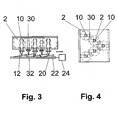
- Frequency tuning elements 10 extend in the resonator cavities 2 and are carried by cam followers 12 which project to the outside of the cavities.
- the cam followers 12 are guided for linear movement further into and out of the resonator cavities.
- the cam followers 12 are biased by springs 16 to a maximally extended position (only one spring is shown at one of the frequency tuning elements, springs at the other tuning elements, also in the other Figures have been omitted to simplify the graphical illustration).
- Figs. 3 and 4 show an alternative arrangement of five resonator cavities forming a bandpass filter. As can be seen from Fig. 4 , the resonators are not arranged in a row but form a V-shape.
- a movable control element 20 is guided for linear movement along a first direction which may be designated as x.
- the outer ends of the cam followers 12 are in sliding contact with the cam surface 22 of the control element 20.
- the contour z(x) of the cam surface is shaped in a predetermined manner such that by movement of the control element 20 the individual cam followers 12 and frequency tuning elements 10 are displaced in a predetermined manner given by the contour of the cam surface.
- a drive 24 for example a step motor, is provided for controlled movement of the control element 20 a drive 24 ( Fig. 3 ), for example a step motor, is provided.
- coupling tuning elements 30 which extend into openings between adjacent resonator cavities 2.
- the coupling tuning elements 30 are mounted and guided in a similar manner as the frequency tuning elements.
- the outer ends of the coupling tuning elements 30 are likewise formed as cam followers 32 arranged to be in sliding contact with the cam surface 22 of the control element 20.
- the positioning of the coupling tuning elements 30 may be varied in a predetermined way together with the adjustment of the centre frequencies of the resonators by the frequency tuning elements 20.
- the control element has a cam surface with nine ramps, wherein five ramps are associated with the five cam followers 12 of the five frequency tuning elements of the filter of Figures 3 and 4 , and four ramps are associated with the cam followers 32 of the coupling tuning elements of the filter.
- each ramp is sliding along the associated cam follower 12, 32, and thus the vertical position (in the view of Fig. 3 ) of each cam follower 12, 32 is changed so that a predetermined positioning may be adjusted by moving the control element 20 to the desired position.
- all cam followers are moved in the same sense when the control element is moved, i.e. if the frequency tuning elements 10 are shifted further inside into the resonator cavities, the coupling tuning elements 30 are likewise shifted further into the coupling opening.
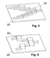
- FIG. 6 An alternative arrangement is shown in Figures 6 to 8 .
- control element 20, as best shown in Fig. 8 has an alternative arrangement.
- the cam surface has a varying contour along two dimensions x and y. This allows, for example, that the cam followers 12 of the frequency tuning elements 10 are sliding on cam surface portions which vary along the direction x, whereas the cam followers of the coupling tuning elements 32 are sliding on ramps oriented in the y direction. This allows, by independently adjusting the position in x and y, to adjust the centre frequencies of the resonators independently of the coupling tuning.
- Fig. 9 shows how the centre frequency of a single resonator of the type as shown in Fig. 1 is varying when the depth at which the frequency tuning element is intruding into the cavity is varied, this depth being designated as tf.
- the variation of the centre frequency of the resonator is shown for three different cavity dimension, namely three different heights of the cavity hc.
- Fig. 10 the behaviour of an exemplary bandpass filter comprising five resonators is shown.
- the return loss S11 is shown in dashed lines and the transmission S21 in full lines.
- the bandpass filter has a centre frequency of about 1400 MHz.
- the centre frequencies of the resonators are increased such that the centre frequency of the filter is about 2000 MHz.
- the centre frequency of the filter is adjusted to 2600 MHz. This increase of the centre frequency is achieved by moving the frequency tuning elements to lower intrusion lengths into the cavities, i.e. by letting the cam followers 12 slide down the cam surface 22, for example by moving the control elements 20 of Figure 3 to the right hand direction.
- the bandwidth of the filter is increasing with increasing centre frequencies. More precisely, the bandwidth of the filter is proportional to the centre frequency.
- Fig. 13 shows that a variation of the centre frequency also leads to a variation in the coupling of resonators.
- Fig. 13 shows the coupling factor k (in units of 10 -3 ) of adjacent first and second cavity resonators as a function of the coupling tuning adjustment length tk, for three different values of the intruding length tf of the frequency tuning elements into the resonators cavities.
- their coupling k is also increasing which contributes to the increasing bandwidth discussed above.
- a coupling between the first and second resonator of the exemplary five resonators of the filter is shown as decreasing with increasing centre frequency.
- This decreasing coupling may be achieved by displacing the coupling elements in a manner so that the coupling reduction as shown in Fig. 12 is achieved.
- the shape of the cam surface portions effective for the cam followers 32 of the coupling tuning elements 30 may be chosen in relation to the cam surface portions effective for the cam followers 12 of the frequency tuning elements 12 such that the bandwidth is maintained constant when the centre frequency of the band pass is adjusted.
- a further schematical view of a single resonator which may be used in a filter according to the invention is shown.
- This resonator is shown to be equipped with a tuning screw 40.
- This tuning screw 40 may be useful in addition to the possible adjustment by way of the frequency tuning elements in order to allow to compensate for manufacturing tolerances in large scale production of filters.
- the tuning may be performed using the cam surface, cam followers and tuning elements.
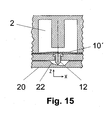
- Fig. 15 shows an alternative arrangement of a cam follower 12 and a frequency tuning element 20.
- the cam follower 12 does not extend into the resonator cavity but only up to a flexible wall portion of the resonator cavity 2.
- the cam follower 12 abuts against a cam surface 22 of a control element 20, and the position of the cam follower 12 may be adjusted by moving the control element 20 to a desired position.
- Fig. 15 shows only a partial view of a single resonator whereas the complete filter has more resonators and more tuning elements.
- frequency and coupling tuning utilising the cam control mechanism of the present invention has been described. It is evident that other tuning elements may be controlled and adjusted in the same manner for, example cross-coupling tuning element, tuning elements for coupling electromagnetic energy to the filter (input) or for extracting electromagnetic energy from the filter (output), etc.. It is noted that in general the input and output side of the filter is interchangeable depending on the intended operation.
Landscapes
- Physics & Mathematics (AREA)
- Electromagnetism (AREA)
- Control Of Motors That Do Not Use Commutators (AREA)
Claims (11)
- Filtre passe-bande accordable, comprenant une pluralité de cavités résonnantes (2), chaque cavité résonnante étant équipée d'un élément mobile (10) d'accord de fréquence s'étendant au moins partiellement dans la cavité (2), et un mécanisme de commande ayant un élément de commande mobile (20), dans lequel les éléments d'accord de fréquence (10) et l'élément de commande (20) sont agencés de façon qu'un mouvement de réglage de l'élément de commande mobile (20) provoque un déplacement simultané des éléments d'accord (10) par rapport aux cavités résonnantes (2) en fonction du mouvement de réglage de l'élément de commande (20) afin de régler les fréquences centrales des cavités résonnantes (2), dans lequel
chaque élément d'accord de fréquence (10) comporte un galet de came (12) qui fait saillie à l'extérieur depuis une paroi de la cavité résonnante respective (2) et qui est guidé pour un mouvement de déplacement dans celui-ci afin de permettre le réglage de la position de l'élément d'accord de fréquence (10) en faisant coulisser le galet de came (12) plus loin vers l'intérieur ou l'extérieur par rapport à la paroi de la cavité résonnante ;
l'élément de commande (20) comporte une surface de guidage (22) à profil prédéterminé, l'élément de commande (20) et les galets de cames (12) étant mutuellement disposés de façon que la surface de guidage soit au contact, de manière glissante, d'une extrémité extérieure de chacun des galets de cames (12), l'élément de commande (20) étant monté pour effectuer un mouvement linéaire dans une première direction afin de modifier la position de la surface de guidage par rapport aux galets de cames (12), et
un moyen d'entraînement (24) est prévu pour régler la position de l'élément de commande (20) dans la première direction afin d'obtenir une position réglée voulue de façon que chacun des galets de cames (12), et donc son élément d'accord de fréquence correspondant (10), soit réglé comme déterminé par le profil de la surface de guidage (22),
caractérisé en ce que
les cavités résonnantes (2) sont couplées par couplage d'ouvertures entre des cavités résonnantes adjacentes (2), et des éléments d'accord de couplage mobiles (30) s'étendant jusque dans les ouvertures de couplage, les éléments d'accord de couplage étant pourvus de galets de cames (32) qui font saillie à l'extérieur des cavités (2) et qui sont mobiles de la même manière que les galets de cames (12) des éléments d'accord de fréquence (10), et l'élément de commande (20) et les galets de cames (32) des éléments d'accord de couplage (30) étant disposés de façon que les extrémités extérieures des galets de cames (32) soient au contact, de manière glissante, de la surface de guidage (22) afin que la position prise par la surface de guidage (22) détermine, outre la position prise par les éléments d'accord de fréquence (10), la position prise par les éléments d'accord de couplage (30). - Filtre passe-bande accordable selon la revendication 1, dans lequel les cavités résonnantes (2) sont disposés en série dans la première direction.
- Filtre passe-bande accordable selon l'une quelconque des revendications précédentes, dans lequel le galet de came (12) comporte un axe qui possède à son extrémité extérieure un bout conique et qui porte à son extrémité intérieure un élément diélectrique (10) d'accord de fréquence.
- Filtre passe-bande accordable selon l'une quelconque des revendications 1 et 2, dans lequel le galet de came (12) comporte un axe avec, à son extrémité extérieure, un bout conique qui, à son extrémité intérieure, bute contre une partie formant paroi flexible (10') de la cavité résonnante (2) qui constitue l'élément mobile d'accord de fréquence.
- Filtre passe-bande accordable selon l'une quelconque des revendications précédentes, dans lequel la surface de guidage (22) de l'élément de commande (20) a un profil comportant une série de parties s'élevant de façon continue, suivies de parties descendantes.
- Filtre passe-bande accordable selon l'une quelconque des revendications précédentes, dans lequel le moyen d'entraînement (24) est constitué par un moteur pas à pas.
- Filtre passe-bande accordable selon l'une quelconque des revendications précédentes, dans lequel l'élément de commande (20) est monté pour se déplacer dans une seconde direction, différente de la première direction, et dans lequel le profil de la surface de guidage dans la première direction (z(x)) varie dans la seconde direction (y) de l'élément de commande (20).
- Filtre passe-bande accordable selon la revendication 5, dans lequel l'élément de commande (20) est une plaque à surface de guidage à trois dimensions qui définit une hauteur de dépassement z dépendant de la position relative x, y sur la plaque, z (x, y) définissant le profil de la surface de guidage (22) dans la première direction x à un emplacement y dans la seconde direction.
- Filtre passe-bande accordable selon l'une quelconque des revendications précédentes, dans lequel un circuit de couplage transversal est prévu entre deux des cavités résonnantes et dans lequel est prévu un élément mobile d'accord de couplage transversal qui s'étend dans le circuit de couplage transversal, l'élément d'accord de couplage transversal comportant un galet de came qui fait saillie à l'extérieur et qui est mobile de la même manière que les galets de cames des éléments d'accord de fréquence, et dans lequel l'élément de commande et le galet de came de l'élément d'accord de couplage transversal sont disposés de façon que l'extrémité extérieure du galet de came soit au contact, de manière glissante, de la surface de guidage afin que la position prise par la surface de guidage détermine, outre la position prise par les éléments d'accord de fréquence, la position prise par l'élément d'accord de couplage transversal.
- Filtre passe-bande accordable selon l'une quelconque des revendications précédentes, dans lequel un circuit d'entrée pour appliquer une énergie électromagnétique au filtre passe-bande est pourvu d'un élément mobile d'accord d'entrée qui s'étend dans le circuit d'entrée, l'élément d'accord d'entrée comportant un galet de came qui fait saillie à l'extérieur et qui est mobile de la même manière que les galets de cames des éléments d'accord de fréquence, et dans lequel l'élément de commande et le galet de came de l'élément d'accord d'entrée sont disposés de façon que l'extrémité extérieure du galet de came soit au contact, de manière glissante, de la surface de guidage afin que la position prise par la surface de guidage détermine, outre la position prise par les éléments d'accord de fréquence, la position prise par l'élément d'accord d'entrée.
- Filtre passe-bande accordable selon l'une quelconque des revendications précédentes, dans lequel un circuit de sortie pour extraire une énergie électromagnétique du filtre passe-bande est pourvu d'un élément mobile d'accord de sortie qui s'étend dans le circuit de sortie, l'élément d'accord de sortie comportant un galet de came qui fait saillie à l'extérieur et qui est mobile de la même manière que les galets de cames des éléments d'accord de fréquence, et dans lequel l'élément de commande et le galet de came de l'élément d'accord de sortie sont disposés de façon que l'extrémité extérieure du galet de came soit au contact, de manière glissante, de la surface de guidage afin que la position prise par la surface de guidage détermine, outre la position prise par les éléments d'accord de fréquence, la position prise par l'élément d'accord de sortie.
Priority Applications (2)
| Application Number | Priority Date | Filing Date | Title |
|---|---|---|---|
| EP20060015381 EP1885018B1 (fr) | 2006-07-24 | 2006-07-24 | Filtre bandepassante accordable |
| DE200660008927 DE602006008927D1 (de) | 2006-07-24 | 2006-07-24 | Abstimmbar Bandpassfilter |
Applications Claiming Priority (1)
| Application Number | Priority Date | Filing Date | Title |
|---|---|---|---|
| EP20060015381 EP1885018B1 (fr) | 2006-07-24 | 2006-07-24 | Filtre bandepassante accordable |
Publications (2)
| Publication Number | Publication Date |
|---|---|
| EP1885018A1 EP1885018A1 (fr) | 2008-02-06 |
| EP1885018B1 true EP1885018B1 (fr) | 2009-09-02 |
Family
ID=37487481
Family Applications (1)
| Application Number | Title | Priority Date | Filing Date |
|---|---|---|---|
| EP20060015381 Expired - Fee Related EP1885018B1 (fr) | 2006-07-24 | 2006-07-24 | Filtre bandepassante accordable |
Country Status (2)
| Country | Link |
|---|---|
| EP (1) | EP1885018B1 (fr) |
| DE (1) | DE602006008927D1 (fr) |
Families Citing this family (5)
| Publication number | Priority date | Publication date | Assignee | Title |
|---|---|---|---|---|
| EP2031693B1 (fr) * | 2007-08-28 | 2014-04-30 | ACE Technology | Filtre réglable de fréquence |
| EP2099091B1 (fr) | 2008-03-04 | 2017-11-22 | HMD global Oy | Filtre de bande de fréquence radio variable |
| US8704617B2 (en) | 2008-08-07 | 2014-04-22 | Ace Technologies Corp. | Tunable filter for expanding the tuning range |
| US8362853B2 (en) * | 2009-06-19 | 2013-01-29 | Qualcomm Incorporated | Tunable MEMS resonators |
| EP3207587B1 (fr) * | 2014-10-15 | 2021-01-20 | Telefonaktiebolaget LM Ericsson (publ) | Structure de guide d'ondes électriquement accordable |
Family Cites Families (4)
| Publication number | Priority date | Publication date | Assignee | Title |
|---|---|---|---|---|
| US3693115A (en) * | 1970-12-28 | 1972-09-19 | American Electronic Lab | Mechanical tunable bandpass filter |
| US3838308A (en) * | 1973-11-05 | 1974-09-24 | Varian Associates | Gang-tuned multicavity microwave tube |
| US5977849A (en) * | 1997-07-22 | 1999-11-02 | Huhges Electronics Corporation | Variable topography electromagnetic wave tuning device, and operating method |
| KR100769657B1 (ko) * | 2003-08-23 | 2007-10-23 | 주식회사 케이엠더블유 | 무선 주파수 대역 가변 필터 |
-
2006
- 2006-07-24 EP EP20060015381 patent/EP1885018B1/fr not_active Expired - Fee Related
- 2006-07-24 DE DE200660008927 patent/DE602006008927D1/de active Active
Also Published As
| Publication number | Publication date |
|---|---|
| EP1885018A1 (fr) | 2008-02-06 |
| DE602006008927D1 (de) | 2009-10-15 |
Similar Documents
| Publication | Publication Date | Title |
|---|---|---|
| EP1885018B1 (fr) | Filtre bandepassante accordable | |
| EP1604425B1 (fr) | Filtre de resonateur | |
| JP4178264B2 (ja) | チューナブルフィルタ | |
| US9083071B2 (en) | Microwave and millimeter-wave compact tunable cavity filter | |
| US6147577A (en) | Tunable ceramic filters | |
| US9614265B2 (en) | Variable high frequency filter device and assembly | |
| FI125652B (fi) | Säädettävä resonaattorisuodin | |
| JP2011009806A (ja) | チューナブル帯域通過フィルタ | |
| EP1852936B1 (fr) | Résonateur à cavité reconfigurable doté d'éléments micro-électromécaniques mobiles en tant que moyen de réglage | |
| KR101766698B1 (ko) | 유전체 공진기를 이용하는 소형 rf 필터 | |
| US20120161905A1 (en) | Resonant element and resonator filter with frequency-tunable layer structure and method of tuning frequency of resonator filter | |
| US4890079A (en) | Di-electric bandpass filter | |
| US6351198B1 (en) | Dielectric filter, duplexer, and communication apparatus | |
| KR20090089568A (ko) | 슬라이딩 방식을 이용한 주파수 튜너블 필터 | |
| KR20150016069A (ko) | 가변 고주파 필터 장치 및 어셈블리 | |
| EP2203953B1 (fr) | Filtre accordable et son procédé d'utilisation | |
| EP1885017A1 (fr) | Filtre passe-bande accordable | |
| WO2018069864A1 (fr) | Filtre passe-bande accordable | |
| WO2010147418A2 (fr) | Appareil de commande de couplage transversal et filtre à cavité rf le comportant | |
| WO2010033057A1 (fr) | Procédé et système permettant d'exercer un filtrage au sein d'un réseau de communication radio sans fil | |
| US6150905A (en) | Dielectric filter with through-hole having large and small diameter portions and a coupling adjustment portion | |
| EP0987787A2 (fr) | Cavité hyperfréquence avec paroi terminale démontable | |
| KR101009276B1 (ko) | 안정적인 슬라이딩 구조의 튜너블 필터 | |
| EP3207587B1 (fr) | Structure de guide d'ondes électriquement accordable | |
| EP3078074B1 (fr) | Filtre haute fréquence à structure coaxiale |
Legal Events
| Date | Code | Title | Description |
|---|---|---|---|
| PUAI | Public reference made under article 153(3) epc to a published international application that has entered the european phase |
Free format text: ORIGINAL CODE: 0009012 |
|
| AK | Designated contracting states |
Kind code of ref document: A1 Designated state(s): AT BE BG CH CY CZ DE DK EE ES FI FR GB GR HU IE IS IT LI LT LU LV MC NL PL PT RO SE SI SK TR |
|
| AX | Request for extension of the european patent |
Extension state: AL BA HR MK YU |
|
| 17P | Request for examination filed |
Effective date: 20080430 |
|
| 17Q | First examination report despatched |
Effective date: 20080530 |
|
| AKX | Designation fees paid |
Designated state(s): DE FR GB |
|
| RAP1 | Party data changed (applicant data changed or rights of an application transferred) |
Owner name: PANASONIC CORPORATION |
|
| GRAP | Despatch of communication of intention to grant a patent |
Free format text: ORIGINAL CODE: EPIDOSNIGR1 |
|
| GRAS | Grant fee paid |
Free format text: ORIGINAL CODE: EPIDOSNIGR3 |
|
| GRAA | (expected) grant |
Free format text: ORIGINAL CODE: 0009210 |
|
| AK | Designated contracting states |
Kind code of ref document: B1 Designated state(s): DE FR GB |
|
| REF | Corresponds to: |
Ref document number: 602006008927 Country of ref document: DE Date of ref document: 20091015 Kind code of ref document: P |
|
| PLBE | No opposition filed within time limit |
Free format text: ORIGINAL CODE: 0009261 |
|
| STAA | Information on the status of an ep patent application or granted ep patent |
Free format text: STATUS: NO OPPOSITION FILED WITHIN TIME LIMIT |
|
| 26N | No opposition filed |
Effective date: 20100603 |
|
| REG | Reference to a national code |
Ref country code: DE Ref legal event code: R084 Ref document number: 602006008927 Country of ref document: DE Effective date: 20111010 |
|
| PGFP | Annual fee paid to national office [announced via postgrant information from national office to epo] |
Ref country code: DE Payment date: 20140716 Year of fee payment: 9 |
|
| PGFP | Annual fee paid to national office [announced via postgrant information from national office to epo] |
Ref country code: FR Payment date: 20140708 Year of fee payment: 9 Ref country code: GB Payment date: 20140723 Year of fee payment: 9 |
|
| REG | Reference to a national code |
Ref country code: DE Ref legal event code: R119 Ref document number: 602006008927 Country of ref document: DE |
|
| GBPC | Gb: european patent ceased through non-payment of renewal fee |
Effective date: 20150724 |
|
| PG25 | Lapsed in a contracting state [announced via postgrant information from national office to epo] |
Ref country code: GB Free format text: LAPSE BECAUSE OF NON-PAYMENT OF DUE FEES Effective date: 20150724 Ref country code: DE Free format text: LAPSE BECAUSE OF NON-PAYMENT OF DUE FEES Effective date: 20160202 |
|
| REG | Reference to a national code |
Ref country code: FR Ref legal event code: ST Effective date: 20160331 |
|
| PG25 | Lapsed in a contracting state [announced via postgrant information from national office to epo] |
Ref country code: FR Free format text: LAPSE BECAUSE OF NON-PAYMENT OF DUE FEES Effective date: 20150731 |