EP1884616A1 - Open/Close Member Control Apparatus - Google Patents
Open/Close Member Control Apparatus Download PDFInfo
- Publication number
- EP1884616A1 EP1884616A1 EP07113232A EP07113232A EP1884616A1 EP 1884616 A1 EP1884616 A1 EP 1884616A1 EP 07113232 A EP07113232 A EP 07113232A EP 07113232 A EP07113232 A EP 07113232A EP 1884616 A1 EP1884616 A1 EP 1884616A1
- Authority
- EP
- European Patent Office
- Prior art keywords
- window
- open
- closing operation
- pinch
- close member
- Prior art date
- Legal status (The legal status is an assumption and is not a legal conclusion. Google has not performed a legal analysis and makes no representation as to the accuracy of the status listed.)
- Granted
Links
Images




Classifications
-
- E—FIXED CONSTRUCTIONS
- E05—LOCKS; KEYS; WINDOW OR DOOR FITTINGS; SAFES
- E05F—DEVICES FOR MOVING WINGS INTO OPEN OR CLOSED POSITION; CHECKS FOR WINGS; WING FITTINGS NOT OTHERWISE PROVIDED FOR, CONCERNED WITH THE FUNCTIONING OF THE WING
- E05F15/00—Power-operated mechanisms for wings
- E05F15/60—Power-operated mechanisms for wings using electrical actuators
- E05F15/603—Power-operated mechanisms for wings using electrical actuators using rotary electromotors
- E05F15/665—Power-operated mechanisms for wings using electrical actuators using rotary electromotors for vertically-sliding wings
- E05F15/689—Power-operated mechanisms for wings using electrical actuators using rotary electromotors for vertically-sliding wings specially adapted for vehicle windows
- E05F15/695—Control circuits therefor
-
- E—FIXED CONSTRUCTIONS
- E05—LOCKS; KEYS; WINDOW OR DOOR FITTINGS; SAFES
- E05F—DEVICES FOR MOVING WINGS INTO OPEN OR CLOSED POSITION; CHECKS FOR WINGS; WING FITTINGS NOT OTHERWISE PROVIDED FOR, CONCERNED WITH THE FUNCTIONING OF THE WING
- E05F15/00—Power-operated mechanisms for wings
-
- E—FIXED CONSTRUCTIONS
- E05—LOCKS; KEYS; WINDOW OR DOOR FITTINGS; SAFES
- E05F—DEVICES FOR MOVING WINGS INTO OPEN OR CLOSED POSITION; CHECKS FOR WINGS; WING FITTINGS NOT OTHERWISE PROVIDED FOR, CONCERNED WITH THE FUNCTIONING OF THE WING
- E05F15/00—Power-operated mechanisms for wings
- E05F15/40—Safety devices, e.g. detection of obstructions or end positions
- E05F15/41—Detection by monitoring transmitted force or torque; Safety couplings with activation dependent upon torque or force, e.g. slip couplings
-
- E—FIXED CONSTRUCTIONS
- E05—LOCKS; KEYS; WINDOW OR DOOR FITTINGS; SAFES
- E05Y—INDEXING SCHEME ASSOCIATED WITH SUBCLASSES E05D AND E05F, RELATING TO CONSTRUCTION ELEMENTS, ELECTRIC CONTROL, POWER SUPPLY, POWER SIGNAL OR TRANSMISSION, USER INTERFACES, MOUNTING OR COUPLING, DETAILS, ACCESSORIES, AUXILIARY OPERATIONS NOT OTHERWISE PROVIDED FOR, APPLICATION THEREOF
- E05Y2201/00—Constructional elements; Accessories therefor
- E05Y2201/40—Motors; Magnets; Springs; Weights; Accessories therefor
- E05Y2201/404—Function thereof
- E05Y2201/41—Function thereof for closing
-
- E—FIXED CONSTRUCTIONS
- E05—LOCKS; KEYS; WINDOW OR DOOR FITTINGS; SAFES
- E05Y—INDEXING SCHEME ASSOCIATED WITH SUBCLASSES E05D AND E05F, RELATING TO CONSTRUCTION ELEMENTS, ELECTRIC CONTROL, POWER SUPPLY, POWER SIGNAL OR TRANSMISSION, USER INTERFACES, MOUNTING OR COUPLING, DETAILS, ACCESSORIES, AUXILIARY OPERATIONS NOT OTHERWISE PROVIDED FOR, APPLICATION THEREOF
- E05Y2201/00—Constructional elements; Accessories therefor
- E05Y2201/40—Motors; Magnets; Springs; Weights; Accessories therefor
- E05Y2201/43—Motors
- E05Y2201/434—Electromotors; Details thereof
-
- E—FIXED CONSTRUCTIONS
- E05—LOCKS; KEYS; WINDOW OR DOOR FITTINGS; SAFES
- E05Y—INDEXING SCHEME ASSOCIATED WITH SUBCLASSES E05D AND E05F, RELATING TO CONSTRUCTION ELEMENTS, ELECTRIC CONTROL, POWER SUPPLY, POWER SIGNAL OR TRANSMISSION, USER INTERFACES, MOUNTING OR COUPLING, DETAILS, ACCESSORIES, AUXILIARY OPERATIONS NOT OTHERWISE PROVIDED FOR, APPLICATION THEREOF
- E05Y2400/00—Electronic control; Electrical power; Power supply; Power or signal transmission; User interfaces
- E05Y2400/10—Electronic control
- E05Y2400/52—Safety arrangements associated with the wing motor
- E05Y2400/525—Car-jacking prevention
-
- E—FIXED CONSTRUCTIONS
- E05—LOCKS; KEYS; WINDOW OR DOOR FITTINGS; SAFES
- E05Y—INDEXING SCHEME ASSOCIATED WITH SUBCLASSES E05D AND E05F, RELATING TO CONSTRUCTION ELEMENTS, ELECTRIC CONTROL, POWER SUPPLY, POWER SIGNAL OR TRANSMISSION, USER INTERFACES, MOUNTING OR COUPLING, DETAILS, ACCESSORIES, AUXILIARY OPERATIONS NOT OTHERWISE PROVIDED FOR, APPLICATION THEREOF
- E05Y2400/00—Electronic control; Electrical power; Power supply; Power or signal transmission; User interfaces
- E05Y2400/10—Electronic control
- E05Y2400/52—Safety arrangements associated with the wing motor
- E05Y2400/53—Wing impact prevention or reduction
- E05Y2400/54—Obstruction or resistance detection
- E05Y2400/57—Disabling thereof
-
- E—FIXED CONSTRUCTIONS
- E05—LOCKS; KEYS; WINDOW OR DOOR FITTINGS; SAFES
- E05Y—INDEXING SCHEME ASSOCIATED WITH SUBCLASSES E05D AND E05F, RELATING TO CONSTRUCTION ELEMENTS, ELECTRIC CONTROL, POWER SUPPLY, POWER SIGNAL OR TRANSMISSION, USER INTERFACES, MOUNTING OR COUPLING, DETAILS, ACCESSORIES, AUXILIARY OPERATIONS NOT OTHERWISE PROVIDED FOR, APPLICATION THEREOF
- E05Y2400/00—Electronic control; Electrical power; Power supply; Power or signal transmission; User interfaces
- E05Y2400/80—User interfaces
- E05Y2400/85—User input means
- E05Y2400/856—Actuation thereof
- E05Y2400/858—Actuation thereof by body parts, e.g. by feet
- E05Y2400/86—Actuation thereof by body parts, e.g. by feet by hand
-
- E—FIXED CONSTRUCTIONS
- E05—LOCKS; KEYS; WINDOW OR DOOR FITTINGS; SAFES
- E05Y—INDEXING SCHEME ASSOCIATED WITH SUBCLASSES E05D AND E05F, RELATING TO CONSTRUCTION ELEMENTS, ELECTRIC CONTROL, POWER SUPPLY, POWER SIGNAL OR TRANSMISSION, USER INTERFACES, MOUNTING OR COUPLING, DETAILS, ACCESSORIES, AUXILIARY OPERATIONS NOT OTHERWISE PROVIDED FOR, APPLICATION THEREOF
- E05Y2800/00—Details, accessories and auxiliary operations not otherwise provided for
- E05Y2800/25—Emergency conditions
- E05Y2800/252—Emergency conditions the elements functioning only in case of emergency
-
- E—FIXED CONSTRUCTIONS
- E05—LOCKS; KEYS; WINDOW OR DOOR FITTINGS; SAFES
- E05Y—INDEXING SCHEME ASSOCIATED WITH SUBCLASSES E05D AND E05F, RELATING TO CONSTRUCTION ELEMENTS, ELECTRIC CONTROL, POWER SUPPLY, POWER SIGNAL OR TRANSMISSION, USER INTERFACES, MOUNTING OR COUPLING, DETAILS, ACCESSORIES, AUXILIARY OPERATIONS NOT OTHERWISE PROVIDED FOR, APPLICATION THEREOF
- E05Y2900/00—Application of doors, windows, wings or fittings thereof
- E05Y2900/50—Application of doors, windows, wings or fittings thereof for vehicles
- E05Y2900/53—Type of wing
- E05Y2900/55—Windows
Definitions
- the present invention relates to an open/close member control apparatus for opening/closing an open/close member such as a window in a vehicle.
- a window opening/closing control apparatus mounted on a vehicle is an apparatus for opening/closing a window by vertically moving a window glass in a door by rotating a motor forward or reverse in accordance with an operation of a switch.
- a power window apparatus having a manual mode of manually opening/closing a window and an automatic mode of automatically opening/closing a window.
- Japanese Unexamined Patent Application Publication No. 2001-118465 discloses an operation switch for a power window apparatus capable of switching five operation modes of a manual closing mode, an automatic closing mode, a manual opening mode, an automatic opening mode, and a neutral (stop) mode.
- a window closing or opening operation is performed only for the period of time in which an operation knob of a switch is manually held in the position of the manual closing mode or the manual opening mode.
- the window closing or opening operation stops.
- the window closing operation or the window opening operation continues.
- the change amount of the rotation speed of the motor is compared with a predetermined threshold. When the amount of change does not exceed the threshold, it is determined that no pinch has occurred. When the amount of change exceeds the threshold, it is determined that pinch has occurred. In such a manner, whether pinch has occurred or not can be detected. Alternatively, by using the amount of change in current flowing in the motor in place of the amount of change in the rotation speed of the motor, whether pinch has occurred or not can be detected.
- Japanese Patent No. 3, 157, 011 discloses a technique that after occurrence of pinch is determined and a window is switched to the opening operation or stop, when a switch is operated to close the window, the window is forcedly closed.
- Japanese Unexamined Patent Application Publication No. S61-64983 discloses that, in the case where occurrence of pinch is determined, when it is detected that a switching operation of closing a window is performed a predetermined number of times, the window is forcedly closed.
- Japanese Patent No. 3,578,568 discloses a technique of forcedly closing a window in the case where pinch of a foreign matter is determined a predetermined number of times in a row.
- the power window apparatus can prevent an object or human body caught in a window from being damaged by providing the pinch detecting function.
- the pinch detecting function due to the existence of the pinch detecting function, the following problems arise.
- a ruffian tries to enter a vehicle compartment from a window which is being closed in automatic closing operation, there is a case such that the closing window touches the body of the ruffian and occurrence of pinch is determined.
- the closing operation of the window is then switched to the opening operation, and the window is open.
- the window is open, the ruffian can easily enter the compartment, and the driver may be harmed. Consequently, to prevent a ruffian from easily entering the compartment, it is performed that the window is not open even if pinch is detected in the case where the switch is operated to an automatic closing mode to close the window automatically and, after that, the switch is maintained in the automatic closing mode.
- An object of the present invention is to provide an open/close member control apparatus capable of blocking entry of a ruffian even if forced closing operation is cancelled during closing operation of an open/close member by the forced closing operation and suppressing damage on an object which is erroneously caught.
- an open/close member control apparatus comprising: a switch for opening/closing an open/close member; a load detector that detects load on the open/close member; and a pinch detector for detecting pinch of a foreign matter in the open/close member on the basis of the load detected by the load detector, the apparatus having a function of forcedly making the open/close member perform closing operation even if pinch is detected by performing a predetermined forced closing operation on the switch, and switching the closing operation of the open/close member to opening operation in the case where the pinch detector detects pinch and the forced closing operation on the switch is not maintained, and continuing the closing operation of the open/close member in the case where the pinch detector detects pinch and the forced closing operation on the switch is maintained, wherein in the case where the pinch detector detects pinch and the forced closing operation of the switch is maintained, when the maintenance of the forced closing operation is cancelled during closing operation of the open/close member, the open/close member is allowed to perform opening operation so that an open amount of the open/close member becomes
- the open amount of the open/close member is smaller than that in normal times. Consequently, entry of a ruffian from the open/close member such as a window is suppressed, and a person on the inside can be prevented from being harmed. In the case where an object is caught by mistake, the open/close member is open without stopping. Consequently, the pinch load is reduced, and the caught object can be prevented from being damaged.
- an open/close member control apparatus comprising: a switch for opening/closing an open/close member; a load detector that detects load on the open/close member; and a pinch detector for detecting pinch of a foreign matter in the open/close member on the basis of the load detected by the load detector, the apparatus having a function of forcedly making the open/close member perform closing operation even if pinch is detected by performing a predetermined forced closing operation on the switch, and switching the closing operation of the open/close member to opening operation in the case where the pinch detector detects pinch and the forced closing operation on the switch is not maintained, and continuing the closing operation of the open/close member in the case where the pinch detector detects pinch and the forced closing operation on the switch is maintained, wherein in the case where the pinch detector detects pinch and the forced closing operation of the switch is maintained, when the maintenance of the forced closing operation is cancelled during closing operation of the open/close member, the open/close member is allowed to perform opening operation so that open speed of the open/close member becomes lower
- the open speed of the open/close member is lower than that in normal times, and the open/close member opens slowly. Consequently, entry of a ruffian from the open/close member such as a window is suppressed, and a person on the inside can be prevented from being harmed. In the case where an object is caught by mistake, the open/close member is open without stopping. Consequently, the pinch load is reduced, and the caught object can be prevented from being damaged.
- the open/close member even if maintenance of the forced closing operation is cancelled and the open/close member is open, the open amount or open speed of the open/close member is smaller/lower than that in normal times. Consequently, entry of a ruffian to the inside can be blocked. In the case where an object is caught, the open/close member opens without stopping, so that damaging of the object caught is suppressed.
- FIG. 1 is a block diagram showing an electric configuration of a power window apparatus as an embodiment of the present invention.
- Reference numeral 1 denotes a control unit made by a CPU for controlling a window opening/closing operation
- 2 denotes a motor drive circuit for driving a motor
- 4 indicates a rotary encoder for outputting a pulse synchronized with rotation of the motor
- 5 indicates a pulse detection circuit for detecting a pulse output from the rotary encoder 4
- 6 indicates a memory such as a ROM and a RAM
- 7 denotes an operation switch for operating opening/closing of a window.
- the memory 6 has an area 6a in which a threshold for determining pinch is set and an area 6b in which a forced closing operation flag to be described later is stored.
- the rotary encoder 4 and the pulse detection circuit 5 together with the control unit 1 correspond to an embodiment of load detector in the present invention.
- the control unit 1 corresponds to an embodiment of pinch detector in the present invention.
- FIG. 1 when the operation switch 7 is operated, a window opening/closing instruction is given to the control unit 1, and the motor 3 is rotated forward or reverse by the motor drive circuit 2.
- a window opening/closing mechanism (which will be described later) interlocked with the motor 3 operates to open/close a window 100.
- the pulse detection circuit 5 detects a pulse output from the rotary encoder 4.
- the control unit 1 calculates an open/close amount of the window 100 and the rotation speed of the motor 3 and controls the rotation of the motor 3 via the motor drive circuit 2.
- FIG. 2 is a schematic configuration diagram showing an example of the operation switch 7.
- the operation switch 7 is constructed by an operation knob 71 swingable in the a-b directions around axis Q as a center, a rod 72 provided integrally with the operation knob 71, and a known slide switch 73.
- Reference numeral 74 denotes an actuator of the slide switch 73, and 20 indicates a cover of a switch unit in which the operation switch 7 is assembled.
- the lower end of the rod 72 is engaged with the actuator 74 of the slide switch 73.
- the actuator 74 moves in the c-d direction via the rod 72, and according to the movement position the contact (not shown) of the slide switch 73 is switched.
- the operation knob 71 can be switched among the positions of an automatic closing mode AC, a manual closing mode MC, a neutral mode N, a manual opening mode MO, and an automatic opening mode AO.
- FIG. 2 shows a state where the operation knob 71 is in the position of the neutral mode N.
- the operation knob 71 is turned by a certain amount in the direction "a" from the position of the neutral mode N to the position of the manual closing mode MC, the manual closing operation of closing the window in the manual mode is performed.
- the operation knob 71 is further turned in the direction "a" from the position of the manual closing mode MC to the position of the automatic closing mode AC, the automatic closing operation of closing the window in the automatic mode is performed.
- the operation knob 71 When the operation knob 71 is turned by a certain amount from the position of the neutral mode N in the direction "b" to the position of the manual opening mode MO, the manual opening operation of opening the window in the manual mode is performed. When the operation knob 71 is further turned in the direction "b" from the position of the manual opening mode MO to the position of the automatic opening mode AO, the automatic opening operation of opening the window in the automatic mode is performed.
- the operation knob 71 is provided with a not-shown spring. When the user moves his/her hand off the turned operation knob 71, the operation knob 71 returns to the position of the neutral mode N by the spring force.
- the window closing or opening operation is performed.
- the window closing or opening operation stops.
- the window closing or opening operation is continuously performed.
- FIG. 3 is a diagram showing an example of a window opening/closing mechanism provided for each of the windows of a vehicle.
- Reference numeral 100 denotes a window of a vehicle
- 101 denotes a window glass which opens/closes the window 100
- 102 indicates a window opening/closing mechanism.
- the window glass 101 performs ascending/descending operation by the operation of the window opening/closing mechanism 102. When the window glass 101 ascends, the window 100 is closed. When the window glass 101 descends, the window 100 is opened.
- the window glass 101 is an embodiment of the open/close member in the present invention.
- the window opening/closing mechanism 102 has a supporting member 103 attached to the lower end of the window glass 101, a first arm 104 whose one end is engaged with the supporting member 103 and whose other end is rotatably supported by a bracket 106, and a second arm 105 whose one end is engaged with the supporting member 103 and whose other end is engaged with a guide member 107. Intermediate parts in the first and second arms 104 and 105 are coupled to each other via a shaft.
- Reference numeral 3 denotes the above-described motor
- reference numeral 4 indicates the above-described rotary encoder.
- the rotary encoder 4 is coupled to the rotary shaft of the motor 3 and outputs pulses of the number proportional to the rotational amount of the motor 3. By counting the pulses output from the rotary encoder 4 within predetermined time, the rotation speed of the motor 3 can be detected. From the output of the rotary encoder 4, the rotation amount of the motor 3 (the movement amount of the window glass 101) can be calculated.
- Reference numeral 109 denotes a pinion rotated by the motor 3
- reference numeral 110 denotes a fan-shaped gear engaged with the pinion 109 and rotating.
- the gear 110 is fixed to the first arm 104.
- the motor 3 can rotate in the forward and reverse directions. By the rotation in the forward and reverse directions, the pinion 109 and the gear 110 are rotated to turn the first arm 104 in the forward/reverse direction.
- the other end of the second arm 105 slides in the lateral direction along a groove in the guide member 107, and the supporting member 103 moves in the vertical direction to make the window glass 101 ascend/descend, thereby opening/closing the window 100.
- the function of detecting pinch of an object is provided. Specifically, as shown in FIG. 4, in the case where an object Z is caught in the clearance of the window glass 101 during closure of the window 100, the pinch is detected and the closing operation of the window 100 is switched to the opening operation. Since the window 100 is automatically closed during the automatic closing operation, to prevent the caught object Z from being damaged, the pinch detecting function acts and the closing operation of the window 100 is inhibited.
- the control unit 1 reads, as needed, the rotation speed of the motor 3 as an output of the pulse detection circuit 5, compares the rotation speed at present with the previous rotation speed and, on the basis of the comparison result, determines whether pinch has occurred or not.
- the load on the motor 3 increases and the rotation speed decreases, so that the amount of change in the speed increases.
- the speed change amount exceeds the threshold stored in the memory 6, it is determined that the object Z has been caught.
- FIG. 5 is a flowchart showing the basic operation of the power window apparatus of the embodiment of the present invention.
- “SW” in the diagram expresses the "operation switch 7" (also in the following flowcharts).
- step S1 when the operation switch 7 is in the position of the manual closing mode MC, the process of the manual closing operation is performed (step S2).
- step S3 when the operation switch 7 is in the position of the automatic closing mode AC, the automatic closing operation is performed (step S4).
- step S5 when the operation switch 7 is in the position of the manual opening mode MO, the manual opening operation is performed (step S6).
- step S7 when the operation switch 7 is in the position of the automatic opening mode AO, the automatic opening operation is performed (step S8).
- step S7 When the operation switch 7 is not in the position of the automatic opening mode AO in step S7, the operation switch 7 is in the position of the neutral mode N and no process is performed.
- the details of the steps S2, S4, S6, and S8 will be described in order hereinbelow.
- FIG. 6 shows detailed procedure of the "manual closing process" in step S2 in FIG. 5.
- the procedure is executed by the CPU constituting the control unit 1.
- the process is finished.
- a forward rotation signal is output from the motor drive circuit 2 to rotate the motor 3 forwardly and the window 100 is closed (step S12).
- step S13 determines the window 100 has been completely closed or not.
- the process is finished.
- the window 100 is not closed completely (NO in step S13)
- step S14 When the operation switch 7 is in the position of the manual closing mode MC (YES in step S14), the CPU returns to step S12 to continue the forward rotation of the motor 3.
- step S15 When the operation switch 7 is not in the position of the manual closing mode MC (NO in step S14), whether the operation switch 7 is in the position of the automatic closing mode AC or not is determined (step S15).
- the CPU moves to the automatic closing process to be described later (FIG. 7 or 8) (step S16).
- step S17 When the operation switch 7 is not in the position of the automatic closing mode AC (NO in step S15), whether the operation switch 7 is in the position of the manual opening mode MO or not is determined (step S17).
- step S17 When the operation switch 7 is in the position of the manual opening mode MO (YES in step S17), the CPU moves to the manual opening process to be described later (FIG. 9) (step S18).
- step S19 When the operation switch 7 is not in the position of the manual opening mode MO (NO in step S17), whether the operation switch 7 is in the position of the automatic opening mode AO or not is determined (step S19).
- step S19 When the operation switch 7 is in the position of the automatic opening mode AO (YES in step S19), the CPU moves to the automatic opening process to be described later (FIG. 10) (step S20).
- the routine is finished without performing any process.
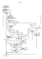
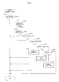
- FIG. 7 shows detailed procedure of the "automatic closing process” in step S4 in FIG. 4, which is the feature of the present invention.
- the procedure is executed by the CPU constituting the control unit 1.
- the forced closing operation flag in the area 6b in the memory 6 is set to "0" (step S21).
- the forced closing operation flag is a flag showing whether the forced closing operation by the operation switch 7 has been performed or not.
- the forced closing operation is an operation performed in such a manner that after the operation switch 7 is operated to start the automatic closing operation, the operation switch 7 is operated again to the "close" side (the automatic closing mode AC or the manual closing mode MC) to forcedly close the window without opening the window even if pinch occurs.
- the forced closing operation flag is set to "1".
- the forced closing operation flag is set to "0".
- step S22 whether the window 100 is completely closed by the automatic closing operation or not is determined on the basis of an output of the rotary encoder 4 (step S22).
- the window 100 is completely closed (YES in step S22)
- the process is finished.
- the window 100 is not completely closed (NO in step S22)
- the routine moves to step S23.
- step S23 a forward rotation signal is output to the motor drive circuit 2 to rotate the motor 3 forward, thereby closing the window 100. Subsequently, whether the window 100 is completely closed or not is determined (step S24). When the window 100 is completely closed (YES in step S24), the process is finished. When the window 100 is not completely closed (NO in step S24), the routine moves to step S25 where whether pinch is detected or not is determined.
- the pinch detection is, as described above, performed by comparing the speed change amount of the motor 3 with a threshold stored in the area 6a in the memory 6. When the speed change amount exceeds the threshold, it is determined that the object Z is caught as shown in FIG. 4.
- step S34 When pinch is not detected (NO in step S25), whether the operation switch 7 is in the position of the manual opening mode MO or not is determined (step S34).
- the routine moves to the manual opening process (FIG. 9) to be described later (step S35).
- step S36 whether the operation switch 7 is in the position of the automatic opening mode AO or not is determined.
- step S37 When the operation switch 7 is in the position of the automatic opening mode AO (NO in step S36), the routine returns to step S23, continues the automatic closing operation, and closes the window 100.
- step S25 when pinch is detected (YES in step S25), the position of the window glass 101 at that time is stored in the memory 6 (step S26). The position can be detected by counting the number of pulses output from the rotary encoder 4. After that, the routine moves to step S27 where the operation switch 7 is in the position of the manual closing mode MC or not is determined.
- step S29 whether the operation switch 7 is in the position of the automatic closing mode AC or not is determined. In the case where the operation switch 7 is not in the position of the automatic closing mode AC (NO in step S29), whether the operation switch 7 is in the position of the manual opening mode MO or not is determined (step S30).
- step S30 If it is not in the position of the manual opening mode MO (NO in step S30), whether the operation switch 7 is in the position of the automatic opening mode AO or not is determined (step S32). In the case where pinch is detected, if the operation switch 7 is not operated, it is determined as NO in all of steps S27, S29, S30 and S32, then the routine moves to step S38.
- step S38 a reverse rotation signal is output from the motor drive circuit 2 to reversely rotate the motor 3, thereby switching the window operation from the closing operation to the opening operation.
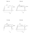
- step S39 whether the forced closing operation flag is "1" or not is determined. In this stage, the forced closing operation is not performed and the forced closing operation flag is "0" (NO in step S39). Consequently, the routine advances to step S41 and whether or not the window is opened by 200 mm or more is determined as shown in FIG. 11A.
- V expresses window opening speed. Above-mentioned 200 mm is a reference value in the normal case where the forced closing operation is not performed.
- the window opening amount can be calculated by using the window position stored in step S26.
- step S41 When the window is not open by 200 mm or more (NO in step S41), the routine returns to step S27. The steps S27, S29, S30, S32, S38, S39 and S41 are repeated, and the window opening operation is continued.
- the window opens by 200 mm or more as shown in FIG. 11A YES in step S41
- the motor 3 is stopped and the operation is finished.
- the normal window reversing operation performed at the time of occurrence of pinch has been described above.
- step S27 the routine advances to step S28 where the forced closing operation flag in the area 6b in the memory 6 is rewritten to "1".
- step S23 a forward rotation signal is output from the motor drive circuit 2 to forwardly rotate the motor 3, thereby closing the window 100. While the switch 7 is maintained in the forced closing operation state, it is determined as YES in step S27 or S29, and the window closing operation continues. Even if pinch occurs, the window 100 is not opened (steps S23 to S29).
- step S30 In the case where the operation switch 7 is operated in the position of the manual opening mode MO in step S30 (YES in step S30), the routine shifts to the manual opening process (step S31) to be described later (FIG. 9). In the case where the operation switch 7 is operated in the position of the automatic opening mode AO in step S32 (YES in step S32), the routine shifts to the automatic opening process (FIG. 10) to be described later (step S33).
- step S38 As described above, a reverse rotation signal is output from the motor drive circuit 2 to reversely rotate the motor 3, and the window operation is switched from the closing operation to the opening operation. Subsequently, whether the forced closing operation flag is "1" or not is determined (step S39).
- step S40 the routine advances to step S40 and whether or not the window is opened by 100 mm or more is determined as shown in FIG. 11B.
- V denotes the window opening speed which is the same value as that in the case of FIG. 11A.
- 100 mm is a reference value in the forced closing operation performed in such a case that a ruffian is assaulting the user.
- the window opening amount can be calculated by using the window position stored in step S26.
- Steps S27, S29, S30, S32, and S38 to S40 are repeated, and the window opening operation is continued.
- the window opens by 100 mm or more as shown in FIG. 11B YES in step S40
- the motor 3 is stopped and the operation is finished.
- the opening amount of the window 100 (the movement amount of the window glass 101) is smaller (100 mm) than that in normal times as shown in FIG. 11B. Consequently, entrance of a ruffian from the window 100 is suppressed, and a person in the vehicle can be prevented from being harmed. In the case where an object is caught by mistake, the window glass 101 opens without being stopped. Therefore, the pinch load decreases, and the caught object can be prevented from being damaged.
- FIG. 8 is a flowchart showing another embodiment of the automatic closing process. The procedure is executed by the CPU constituting the control unit 1.
- the same reference numerals are designated to steps of performing the same processes as those of FIG. 7.
- the window open amount is regulated.
- the window open speed is regulated.
- the steps S21 to S37 are the same as those of FIG. 7, so that they will be briefly described.
- the forced closing operation flag is set to "0" (step S21), and the window closing operation is performed by the automatic closing operation (steps S22 to S24).
- the automatic closing operation is continued.
- the routine shifts to the manual opening process or the automatic opening process (step S35 or S37).
- step S25 When pinch is detected (YES in step S25), the window position is stored (step S26) and, after that, whether the operation switch 7 is operated or not is determined (steps S27, S29, S30 and S32). When the operation switch 7 is not operated, it is determined as NO in all of steps S27, S29, S30 and S32, and the routine shifts to step S42.
- step S42 whether the forced closing operation flag is "1" or not is determined. In this stage, the forced closing operation is not performed and the forced closing operation flag is "0" (NO in step S42), so that the routine shifts to step S44.
- step S44 a reverse rotation signal is output from the motor drive circuit 2 to rotate the motor 3 reversely, thereby switching the window operation from the closing operation to the opening operation.
- the window opens at speed V1 as shown in FIG. 12A.
- V1 is a reference value in the normal case where the forced closing operation is not performed.
- step S45 the routine advances to step S45 and whether or not the window opens by 200 mm or more is determined.
- the window open amount can be calculated by using the window position stored in step S26.
- the routine returns to step S27.
- the steps S27, S29, S30, S32, S42, S44 and S45 are repeated, and the window opening operation is continued.
- the motor 3 is stopped and the operation is finished.
- the normal window reversing operation performed at the time of occurrence of pinch has been described above.
- step S27 and YES in step S29 the forced closing operation flag is rewritten to "1" (step S28), and the motor 3 is rotated forwardly to close the window 100 (step S23). While the forced closing operation is maintained, the window closing operation is continued and, even if pinch occurs, the window 100 is not opened (steps S23 to S29).
- the routine shifts to the manual opening process or the automatic opening process (steps S31, S33).
- step S42 As described above, whether the forced closing operation flag is "1" or not is determined. In this stage, since the forced closing operation is performed and the forced closing operation flag is set to "1" in step S28 (YES in step S42), the routine shifts to step S43.
- step S43 a reverse rotation signal is output from the motor drive circuit 2 to rotate the motor 3 reversely to switch the window operation from the closing operation to the opening operation.
- the window opens at the speed V2 as shown in FIG. 12B.
- an instruction of supplying drive voltage to open the window at the speed V2 to the motor 3 is given from the control unit 1 to the motor drive circuit 2.
- V2 is a reference value in the forced closing operation performed in such a case that a ruffian is assaulting the user, and is smaller than the reference value V1 in the case where no forced closing operation is performed (V2 ⁇ V1). Therefore, in step S43, the window 100 opens at speed lower than that in the case of step S44.
- step S45 the routine advances to step S45 and whether or not the window opens by 200 mm or more is determined.
- the window open amount can be calculated by using the window position stored in the step S26.
- the routine returns to step S27.
- the steps S27, S29, S30, S32, S42, S43 and S45 are repeated, and the window opening operation is continued.
- the motor 3 is stopped to finish the operation.
- FIG. 9 shows detailed procedure of the "manual opening process" in step S6 in FIG. 5.
- the procedure is executed by the CPU constituting the control unit 1.
- the process is finished.
- a reverse rotation signal is output from the motor drive circuit 2 to reversely rotate the motor 3 and the window 100 is opened (step S52).
- step S53 determines the window 100 is completely opened or not.
- the process is finished.
- the window 100 is not opened completely (NO in step S53)
- step S54 When the operation switch 7 is in the position of the manual opening mode MO (YES in step S54), the routine returns to step S52 to continue the reverse rotation of the motor 3.
- step S55 When the operation switch 7 is not in the position of the manual opening mode MO (NO in step S54), whether the operation switch 7 is in the position of the automatic opening mode AO or not is determined (step S55).
- the routine moves to the automatic opening process (step S56) to be described later (FIG. 10).
- step S57 When the operation switch 7 is not in the position of the automatic opening mode AO (NO in step S55), whether the operation switch 7 is in the position of the manual closing mode MC or not is determined (step S57).
- step S57 When the operation switch 7 is in the position of the manual closing mode MC (YES in step S57), the routine moves to the manual closing process described before (FIG. 6) (step S58). When the operation switch 7 is not in the position of the manual closing mode MC (NO in step S57), whether the operation switch 7 is in the position of the automatic closing mode AC or not is determined (step S59). When the operation switch 7 is in the position of the automatic closing mode AC (YES in step S59), the routine moves to the automatic closing process described before (FIG. 7 or 8) (step S60). When the operation switch 7 is not in the position of the automatic closing mode AC (NO in step S59), the routine is finished without performing any process.
- FIG. 10 shows detailed procedure of the "automatic opening process" in step S8 in FIG. 5.
- the procedure is executed by the CPU constituting the control unit 1.
- the process is finished.
- a reverse rotation signal is output from the motor drive circuit 2 to reversely rotate the motor 3, thereby opening the window 100 (step S72).
- step S73 determines the window 100 is completely opened or not.
- the process is finished.
- the window 100 is not completely opened (NO in step S73)
- step S74 When the operation switch 7 is in the position of the manual closing mode MC (YES in step S74), the routine moves to the manual closing process described before (FIG. 6) (step S75). When the operation switch 7 is not in the position of the manual closing mode MC (NO in step S74), whether the operation switch 7 is in the position of the automatic closing mode AC or not is determined (step S76). When the operation switch 7 is in the position of the automatic closing mode AC (YES in step S76), the routine moves to the automatic closing process described before (FIG. 7 or 8) (step S77). When the operation switch 7 is not in the position of the automatic closing mode AC (NO in step S76), the routine returns to step S72 and continues the reverse rotation of the motor 3.
- the present invention can employ not only the foregoing embodiment but also various embodiments.
- the values of 100 mm in step S40 in FIG. 7 and 200 mm in step S41 in FIG. 7 and step S45 in FIG. 8 are an example.
- values other than the above values may be employed as reference values.
- the window when pinch is detected, if the operation switch 7 is maintained in either the automatic closing mode or the manual closing mode, the window is forcedly closed.
- the window when pinch is detected, only in the case where the operation switch 7 is maintained in the automatic closing mode or only in the case where the operation switch 7 is maintained in the manual closing mode, the window may be forcedly closed.
- the same window opening speed V is employed in the case where the window opening amount in the normal times and that in the forced closing operation are made different from each other as shown in FIGS. 11A and 11B.
- the same window opening amount is employed in the case where the window opening speed V1 in the normal times and the window opening speed V2 at the time of forced closing operation are made different from each other as shown in FIGS. 12A and 12B.
- both of the window opening amounts are made different from each other and the window opening speeds are made different from each other in normal times and in the forced closing operation.
- the load on the motor is detected on the basis of the rotation speed of the motor 3 in the foregoing embodiment, instead, the load on the motor may be detected on the basis of the current flowing in the motor 3. In this case, as a load detector, it is sufficient to provide a current detection circuit for detecting motor current.
- a window glass of a vehicle has been described as an open/close member in the foregoing embodiment, the invention can be also applied to the case of controlling an open/close member such as a rear door or a sunroof of a vehicle.
- the invention can be also applied to the case of controlling opening/closing of a door in a building.
Landscapes
- Power-Operated Mechanisms For Wings (AREA)
- Window Of Vehicle (AREA)
- Paper (AREA)
Abstract
Description
- The present invention relates to an open/close member control apparatus for opening/closing an open/close member such as a window in a vehicle.
- A window opening/closing control apparatus (hereinbelow, called "power window apparatus") mounted on a vehicle is an apparatus for opening/closing a window by vertically moving a window glass in a door by rotating a motor forward or reverse in accordance with an operation of a switch. There is a power window apparatus having a manual mode of manually opening/closing a window and an automatic mode of automatically opening/closing a window.
Japanese Unexamined Patent Application Publication No. 2001-118465 - Generally, in the manual mode, a window closing or opening operation is performed only for the period of time in which an operation knob of a switch is manually held in the position of the manual closing mode or the manual opening mode. When the user moves his/her hand off the operation knob and the knob returns to the neutral position, the window closing or opening operation stops. On the other hand, in the automatic mode, once the operation knob is operated to the position of the automatic closing mode or the automatic opening mode, even when the user moves his/her hand off the operation knob and the knob returns to the neutral position, the window closing operation or the window opening operation continues.
- In such a power window apparatus, in the case where an object or a human body is caught in the clearance of the window glass during the window closing operation, it is detected and the window closing operation is switched to the opening operation, thereby preventing the object or human body from being damaged and assuring safety. In particular, in the case of closing the window by the automatic closing operation, if there is no pinch detecting function, the window is continuously closed even after occurrence of a pinch. Consequently, from the viewpoint of avoiding danger, the pinch detecting function is indispensable.
- When pinch occurs, the load on the motor for vertically moving the window glass upward increases and the rotation speed decreases, so that a change amount of the rotation speed of the motor increases. Therefore, the change amount of the rotation speed of the motor is compared with a predetermined threshold. When the amount of change does not exceed the threshold, it is determined that no pinch has occurred. When the amount of change exceeds the threshold, it is determined that pinch has occurred. In such a manner, whether pinch has occurred or not can be detected. Alternatively, by using the amount of change in current flowing in the motor in place of the amount of change in the rotation speed of the motor, whether pinch has occurred or not can be detected.
- However, for example, when the window glass is frozen in winter and, due to this, the load on the motor increases in the window closing operation, although a foreign matter is not caught in the window, there is the possibility that occurrence of pinch is erroneously determined and the window is opened. As a countermeasure against the problem,
Japanese Patent No. 3, 157, 011 Japanese Unexamined Patent Application Publication No. S61-64983 Japanese Patent No. 3,578,568 - As described above, the power window apparatus can prevent an object or human body caught in a window from being damaged by providing the pinch detecting function. On the other hand, due to the existence of the pinch detecting function, the following problems arise.
- For example, if a ruffian tries to enter a vehicle compartment from a window which is being closed in automatic closing operation, there is a case such that the closing window touches the body of the ruffian and occurrence of pinch is determined. The closing operation of the window is then switched to the opening operation, and the window is open. When the window is open, the ruffian can easily enter the compartment, and the driver may be harmed. Consequently, to prevent a ruffian from easily entering the compartment, it is performed that the window is not open even if pinch is detected in the case where the switch is operated to an automatic closing mode to close the window automatically and, after that, the switch is maintained in the automatic closing mode.
- However, there is a case such that while the switch is maintained in the automatic closing mode against entry of a ruffian, the driver moves his/her hand off from the switch by mistake and the forced closing operation is cancelled. In this case, the switch is reset to a normal automatic closing mode. Hence, when pinch is detected, the window is open, and a ruffian can easily enter the compartment. There is another method of not opening the window but stopping the window when pinch is detected. In this case, however, although entry of a ruffian is suppressed, if an object is erroneously caught, the object remains caught. Therefore, if a pinch load is heavy, the object may be damaged.
- An object of the present invention is to provide an open/close member control apparatus capable of blocking entry of a ruffian even if forced closing operation is cancelled during closing operation of an open/close member by the forced closing operation and suppressing damage on an object which is erroneously caught.
- According to the first aspect of the invention, there is provided an open/close member control apparatus comprising: a switch for opening/closing an open/close member; a load detector that detects load on the open/close member; and a pinch detector for detecting pinch of a foreign matter in the open/close member on the basis of the load detected by the load detector, the apparatus having a function of forcedly making the open/close member perform closing operation even if pinch is detected by performing a predetermined forced closing operation on the switch, and switching the closing operation of the open/close member to opening operation in the case where the pinch detector detects pinch and the forced closing operation on the switch is not maintained, and continuing the closing operation of the open/close member in the case where the pinch detector detects pinch and the forced closing operation on the switch is maintained, wherein in the case where the pinch detector detects pinch and the forced closing operation of the switch is maintained, when the maintenance of the forced closing operation is cancelled during closing operation of the open/close member, the open/close member is allowed to perform opening operation so that an open amount of the open/close member becomes smaller than that in normal times.
- In the first aspect of the invention, even if the maintenance of the forced closing operation is cancelled during the closing operation of the open/close member by the forced closing operation on the switch and the open/close member is open due to detection of pinch, the open amount of the open/close member is smaller than that in normal times. Consequently, entry of a ruffian from the open/close member such as a window is suppressed, and a person on the inside can be prevented from being harmed. In the case where an object is caught by mistake, the open/close member is open without stopping. Consequently, the pinch load is reduced, and the caught object can be prevented from being damaged.
- According to the second aspect of the invention, there is provided an open/close member control apparatus comprising: a switch for opening/closing an open/close member; a load detector that detects load on the open/close member; and a pinch detector for detecting pinch of a foreign matter in the open/close member on the basis of the load detected by the load detector, the apparatus having a function of forcedly making the open/close member perform closing operation even if pinch is detected by performing a predetermined forced closing operation on the switch, and switching the closing operation of the open/close member to opening operation in the case where the pinch detector detects pinch and the forced closing operation on the switch is not maintained, and continuing the closing operation of the open/close member in the case where the pinch detector detects pinch and the forced closing operation on the switch is maintained, wherein in the case where the pinch detector detects pinch and the forced closing operation of the switch is maintained, when the maintenance of the forced closing operation is cancelled during closing operation of the open/close member, the open/close member is allowed to perform opening operation so that open speed of the open/close member becomes lower than that in normal times.
- In the second aspect of the invention, even if the maintenance of the forced closing operation is cancelled during the closing operation of the open/close member by the forced closing operation on the switch and the open/close member is open due to detection of pinch, the open speed of the open/close member is lower than that in normal times, and the open/close member opens slowly. Consequently, entry of a ruffian from the open/close member such as a window is suppressed, and a person on the inside can be prevented from being harmed. In the case where an object is caught by mistake, the open/close member is open without stopping. Consequently, the pinch load is reduced, and the caught object can be prevented from being damaged.
- According to the present invention, even if maintenance of the forced closing operation is cancelled and the open/close member is open, the open amount or open speed of the open/close member is smaller/lower than that in normal times. Consequently, entry of a ruffian to the inside can be blocked. In the case where an object is caught, the open/close member opens without stopping, so that damaging of the object caught is suppressed.
-
- FIG. 1 is a block diagram showing an electric configuration of a power window apparatus of the present invention.
- FIG. 2 is a schematic configuration diagram showing an example of an operation switch.
- FIG. 3 is a diagram showing an example of a window opening/closing mechanism.
- FIG. 4 is a diagram showing a state where an object is caught in a window.
- FIG. 5 is a flowchart showing basic operation of the power window apparatus.
- FIG. 6 is a flowchart showing detailed procedure of a manual closing process.
- FIG. 7 is a flowchart showing detailed procedure of an automatic closing process.
- FIG. 8 is a flowchart showing detailed procedure of the automatic closing process in another embodiment.
- FIG. 9 is a flowchart showing detailed procedure of a manual opening process.
- FIG. 10 is a flowchart showing detailed procedure of an automatic opening process.
- FIGS. 11A and 11B are diagrams showing a window opening amount.
- FIGS. 12A and 12B are diagrams showing window opening speed.
- FIG. 1 is a block diagram showing an electric configuration of a power window apparatus as an embodiment of the present invention.
Reference numeral 1 denotes a control unit made by a CPU for controlling a window opening/closing operation, 2 denotes a motor drive circuit for driving amotor motor rotary encoder memory 6 has an area 6a in which a threshold for determining pinch is set and anarea 6b in which a forced closing operation flag to be described later is stored. Therotary encoder 4 and thepulse detection circuit 5 together with thecontrol unit 1 correspond to an embodiment of load detector in the present invention. Thecontrol unit 1 corresponds to an embodiment of pinch detector in the present invention. - In FIG. 1, when the
operation switch 7 is operated, a window opening/closing instruction is given to thecontrol unit 1, and themotor 3 is rotated forward or reverse by themotor drive circuit 2. By the rotation of themotor 3, a window opening/closing mechanism (which will be described later) interlocked with themotor 3 operates to open/close awindow 100. Thepulse detection circuit 5 detects a pulse output from therotary encoder 4. On the basis of the detection result, thecontrol unit 1 calculates an open/close amount of thewindow 100 and the rotation speed of themotor 3 and controls the rotation of themotor 3 via themotor drive circuit 2. - FIG. 2 is a schematic configuration diagram showing an example of the
operation switch 7. Theoperation switch 7 is constructed by anoperation knob 71 swingable in the a-b directions around axis Q as a center, arod 72 provided integrally with theoperation knob 71, and a knownslide switch 73.Reference numeral 74 denotes an actuator of theslide switch operation switch 7 is assembled. The lower end of therod 72 is engaged with theactuator 74 of theslide switch 73. When theoperation knob 71 turns in the a-b direction, theactuator 74 moves in the c-d direction via therod 72, and according to the movement position the contact (not shown) of theslide switch 73 is switched. - The
operation knob 71 can be switched among the positions of an automatic closing mode AC, a manual closing mode MC, a neutral mode N, a manual opening mode MO, and an automatic opening mode AO. FIG. 2 shows a state where theoperation knob 71 is in the position of the neutral mode N. When theoperation knob 71 is turned by a certain amount in the direction "a" from the position of the neutral mode N to the position of the manual closing mode MC, the manual closing operation of closing the window in the manual mode is performed. When theoperation knob 71 is further turned in the direction "a" from the position of the manual closing mode MC to the position of the automatic closing mode AC, the automatic closing operation of closing the window in the automatic mode is performed. When theoperation knob 71 is turned by a certain amount from the position of the neutral mode N in the direction "b" to the position of the manual opening mode MO, the manual opening operation of opening the window in the manual mode is performed. When theoperation knob 71 is further turned in the direction "b" from the position of the manual opening mode MO to the position of the automatic opening mode AO, the automatic opening operation of opening the window in the automatic mode is performed. Theoperation knob 71 is provided with a not-shown spring. When the user moves his/her hand off the turnedoperation knob 71, theoperation knob 71 returns to the position of the neutral mode N by the spring force. - In the manual mode, only for the period of time the
operation knob 71 is continuously held manually in the position of the manual closing mode MC or the manual opening mode MO, the window closing or opening operation is performed. When the user moves his/her hand off theoperation knob 71 and theoperation knob 71 returns to the position of the neutral mode N, the window closing or opening operation stops. On the other hand, in the automatic mode, once theoperation knob 71 is operated to the position of the automatic closing mode AC or the automatic opening mode AO, even the user moves his/her hand off theoperation knob 71 and the knob returns to the position of the neutral mode N, the window closing or opening operation is continuously performed. - FIG. 3 is a diagram showing an example of a window opening/closing mechanism provided for each of the windows of a vehicle.
Reference numeral 100 denotes a window of a vehicle, 101 denotes a window glass which opens/closes thewindow window glass 101 performs ascending/descending operation by the operation of the window opening/closing mechanism 102. When thewindow glass 101 ascends, thewindow 100 is closed. When thewindow glass 101 descends, thewindow 100 is opened. Thewindow glass 101 is an embodiment of the open/close member in the present invention. The window opening/closing mechanism 102 has a supportingmember 103 attached to the lower end of thewindow glass 101, afirst arm 104 whose one end is engaged with the supportingmember 103 and whose other end is rotatably supported by abracket 106, and asecond arm 105 whose one end is engaged with the supportingmember 103 and whose other end is engaged with aguide member 107. Intermediate parts in the first andsecond arms Reference numeral 3 denotes the above-described motor, andreference numeral 4 indicates the above-described rotary encoder. Therotary encoder 4 is coupled to the rotary shaft of themotor 3 and outputs pulses of the number proportional to the rotational amount of themotor 3. By counting the pulses output from therotary encoder 4 within predetermined time, the rotation speed of themotor 3 can be detected. From the output of therotary encoder 4, the rotation amount of the motor 3 (the movement amount of the window glass 101) can be calculated. -
Reference numeral 109 denotes a pinion rotated by themotor 3, andreference numeral 110 denotes a fan-shaped gear engaged with thepinion 109 and rotating. Thegear 110 is fixed to thefirst arm 104. Themotor 3 can rotate in the forward and reverse directions. By the rotation in the forward and reverse directions, thepinion 109 and thegear 110 are rotated to turn thefirst arm 104 in the forward/reverse direction. Accompanying this operation, the other end of thesecond arm 105 slides in the lateral direction along a groove in theguide member 107, and the supportingmember 103 moves in the vertical direction to make thewindow glass 101 ascend/descend, thereby opening/closing thewindow 100. - In the power window apparatus as described above, when the
operation knob 71 is in the position of the automatic closing mode AC in FIG. 2 and the automatic closing operation is performed, the function of detecting pinch of an object is provided. Specifically, as shown in FIG. 4, in the case where an object Z is caught in the clearance of thewindow glass 101 during closure of thewindow 100, the pinch is detected and the closing operation of thewindow 100 is switched to the opening operation. Since thewindow 100 is automatically closed during the automatic closing operation, to prevent the caught object Z from being damaged, the pinch detecting function acts and the closing operation of thewindow 100 is inhibited. - At the time of detecting pinch, the
control unit 1 reads, as needed, the rotation speed of themotor 3 as an output of thepulse detection circuit 5, compares the rotation speed at present with the previous rotation speed and, on the basis of the comparison result, determines whether pinch has occurred or not. When the object Z is caught in thewindow 100 as shown in FIG. 4, the load on themotor 3 increases and the rotation speed decreases, so that the amount of change in the speed increases. When the speed change amount exceeds the threshold stored in thememory 6, it is determined that the object Z has been caught. - FIG. 5 is a flowchart showing the basic operation of the power window apparatus of the embodiment of the present invention. "SW" in the diagram expresses the "
operation switch 7" (also in the following flowcharts). In step S1, when theoperation switch 7 is in the position of the manual closing mode MC, the process of the manual closing operation is performed (step S2). In step S3, when theoperation switch 7 is in the position of the automatic closing mode AC, the automatic closing operation is performed (step S4). In step S5, when theoperation switch 7 is in the position of the manual opening mode MO, the manual opening operation is performed (step S6). In step S7, when theoperation switch 7 is in the position of the automatic opening mode AO, the automatic opening operation is performed (step S8). When theoperation switch 7 is not in the position of the automatic opening mode AO in step S7, theoperation switch 7 is in the position of the neutral mode N and no process is performed. The details of the steps S2, S4, S6, and S8 will be described in order hereinbelow. - FIG. 6 shows detailed procedure of the "manual closing process" in step S2 in FIG. 5. The procedure is executed by the CPU constituting the
control unit 1. First, whether thewindow 100 has been closed completely by the manual closing operation or not is determined on the basis of an output of the rotary encoder 4 (step S11). When thewindow 100 is closed completely (YES in step S11), the process is finished. When thewindow 100 is not closed completely (NO in step S11), a forward rotation signal is output from themotor drive circuit 2 to rotate themotor 3 forwardly and thewindow 100 is closed (step S12). Subsequently, whether thewindow 100 has been completely closed or not is determined (step S13). When thewindow 100 is closed completely (YES in step S13), the process is finished. When thewindow 100 is not closed completely (NO in step S13), whether theoperation switch 7 is in the position of the manual closing mode MC or not is determined (step S14). - When the
operation switch 7 is in the position of the manual closing mode MC (YES in step S14), the CPU returns to step S12 to continue the forward rotation of themotor 3. When theoperation switch 7 is not in the position of the manual closing mode MC (NO in step S14), whether theoperation switch 7 is in the position of the automatic closing mode AC or not is determined (step S15). When theoperation switch 7 is in the position of the automatic closing mode AC (YES in step S15), the CPU moves to the automatic closing process to be described later (FIG. 7 or 8) (step S16). When theoperation switch 7 is not in the position of the automatic closing mode AC (NO in step S15), whether theoperation switch 7 is in the position of the manual opening mode MO or not is determined (step S17). When theoperation switch 7 is in the position of the manual opening mode MO (YES in step S17), the CPU moves to the manual opening process to be described later (FIG. 9) (step S18). When theoperation switch 7 is not in the position of the manual opening mode MO (NO in step S17), whether theoperation switch 7 is in the position of the automatic opening mode AO or not is determined (step S19). When theoperation switch 7 is in the position of the automatic opening mode AO (YES in step S19), the CPU moves to the automatic opening process to be described later (FIG. 10) (step S20). When theoperation switch 7 is not in the position of the automatic opening mode AO (NO in step S19), the routine is finished without performing any process. - FIG. 7 shows detailed procedure of the "automatic closing process" in step S4 in FIG. 4, which is the feature of the present invention. The procedure is executed by the CPU constituting the
control unit 1. First, the forced closing operation flag in thearea 6b in thememory 6 is set to "0" (step S21). The forced closing operation flag is a flag showing whether the forced closing operation by theoperation switch 7 has been performed or not. The forced closing operation is an operation performed in such a manner that after theoperation switch 7 is operated to start the automatic closing operation, theoperation switch 7 is operated again to the "close" side (the automatic closing mode AC or the manual closing mode MC) to forcedly close the window without opening the window even if pinch occurs. When the forced closing operation is performed, the forced closing operation flag is set to "1". When the forced closing operation is not performed, the forced closing operation flag is set to "0". - Next, whether the
window 100 is completely closed by the automatic closing operation or not is determined on the basis of an output of the rotary encoder 4 (step S22). When thewindow 100 is completely closed (YES in step S22), the process is finished. When thewindow 100 is not completely closed (NO in step S22), the routine moves to step S23. - In step S23, a forward rotation signal is output to the
motor drive circuit 2 to rotate themotor 3 forward, thereby closing thewindow 100. Subsequently, whether thewindow 100 is completely closed or not is determined (step S24). When thewindow 100 is completely closed (YES in step S24), the process is finished. When thewindow 100 is not completely closed (NO in step S24), the routine moves to step S25 where whether pinch is detected or not is determined. The pinch detection is, as described above, performed by comparing the speed change amount of themotor 3 with a threshold stored in the area 6a in thememory 6. When the speed change amount exceeds the threshold, it is determined that the object Z is caught as shown in FIG. 4. - When pinch is not detected (NO in step S25), whether the
operation switch 7 is in the position of the manual opening mode MO or not is determined (step S34). When theoperation switch 7 is in the position of the manual opening mode MO (YES in step S34), the routine moves to the manual opening process (FIG. 9) to be described later (step S35). When theoperation switch 7 is not in the position of the manual opening mode MO (NO in step S34), whether theoperation switch 7 is in the position of the automatic opening mode AO or not is determined (step S36) . When theoperation switch 7 is in the position of the automatic opening mode AO (YES in step S36), the routine moves to the automatic opening process (FIG. 10) to be described later (step S37). When theoperation switch 7 is not in the position of the automatic opening mode AO (NO in step S36), the routine returns to step S23, continues the automatic closing operation, and closes thewindow 100. - On the other hand, when pinch is detected (YES in step S25), the position of the
window glass 101 at that time is stored in the memory 6 (step S26). The position can be detected by counting the number of pulses output from therotary encoder 4. After that, the routine moves to step S27 where theoperation switch 7 is in the position of the manual closing mode MC or not is determined. When theoperation switch 7 is not in the position of the manual closing mode MC (NO in step S27), whether theoperation switch 7 is in the position of the automatic closing mode AC or not is determined (step S29). In the case where theoperation switch 7 is not in the position of the automatic closing mode AC (NO in step S29), whether theoperation switch 7 is in the position of the manual opening mode MO or not is determined (step S30). If it is not in the position of the manual opening mode MO (NO in step S30), whether theoperation switch 7 is in the position of the automatic opening mode AO or not is determined (step S32). In the case where pinch is detected, if theoperation switch 7 is not operated, it is determined as NO in all of steps S27, S29, S30 and S32, then the routine moves to step S38. - In step S38, a reverse rotation signal is output from the
motor drive circuit 2 to reversely rotate themotor 3, thereby switching the window operation from the closing operation to the opening operation. Subsequently, whether the forced closing operation flag is "1" or not is determined (step S39). In this stage, the forced closing operation is not performed and the forced closing operation flag is "0" (NO in step S39). Consequently, the routine advances to step S41 and whether or not the window is opened by 200 mm or more is determined as shown in FIG. 11A. V expresses window opening speed. Above-mentioned 200 mm is a reference value in the normal case where the forced closing operation is not performed. The window opening amount can be calculated by using the window position stored in step S26. When the window is not open by 200 mm or more (NO in step S41), the routine returns to step S27. The steps S27, S29, S30, S32, S38, S39 and S41 are repeated, and the window opening operation is continued. When the window opens by 200 mm or more as shown in FIG. 11A (YES in step S41), themotor 3 is stopped and the operation is finished. The normal window reversing operation performed at the time of occurrence of pinch has been described above. - On the other hand, in the case where pinch is detected and the
operation switch 7 is in the forced closing operation state, that is, in the case where theswitch 7 is operated in the position of the manual closing mode MC (YES in step S27) or operated in the position of the automatic closing mode AC (YES in step S29), the routine advances to step S28 where the forced closing operation flag in thearea 6b in thememory 6 is rewritten to "1". The routine then moves to step S23 where a forward rotation signal is output from themotor drive circuit 2 to forwardly rotate themotor 3, thereby closing thewindow 100. While theswitch 7 is maintained in the forced closing operation state, it is determined as YES in step S27 or S29, and the window closing operation continues. Even if pinch occurs, thewindow 100 is not opened (steps S23 to S29). - In the case where the
operation switch 7 is operated in the position of the manual opening mode MO in step S30 (YES in step S30), the routine shifts to the manual opening process (step S31) to be described later (FIG. 9). In the case where theoperation switch 7 is operated in the position of the automatic opening mode AO in step S32 (YES in step S32), the routine shifts to the automatic opening process (FIG. 10) to be described later (step S33). - When the user's hand moves off the
operation switch 7 and theoperation knob 71 returns to the position of the neutral mode N from the position of the automatic closing mode AC or manual closing mode MC in a state where the forced closing operation of theoperation switch 7 continues, it is determined as NO in all of the steps S27, S29, S30 and S32, so that the routine moves to step S38. In step S38, as described above, a reverse rotation signal is output from themotor drive circuit 2 to reversely rotate themotor 3, and the window operation is switched from the closing operation to the opening operation. Subsequently, whether the forced closing operation flag is "1" or not is determined (step S39). In this stage, since the forced closing operation has been already performed and the forced closing operation flag has been set to "1" in step S28 (YES in step S39), the routine advances to step S40 and whether or not the window is opened by 100 mm or more is determined as shown in FIG. 11B. V denotes the window opening speed which is the same value as that in the case of FIG. 11A. Above-mentioned 100 mm is a reference value in the forced closing operation performed in such a case that a ruffian is assaulting the user. The window opening amount can be calculated by using the window position stored in step S26. When the window is not open by 100 mm or more (NO in step S40), the routine returns to step S27. Steps S27, S29, S30, S32, and S38 to S40 are repeated, and the window opening operation is continued. When the window opens by 100 mm or more as shown in FIG. 11B (YES in step S40), themotor 3 is stopped and the operation is finished. - As described above, in the embodiment of FIG. 7, even when the user moves his/her hand off the
switch 7 during the closing operation ofwindow 100 by the forced closing operation of theoperation switch 7, continuation of the forced closing operation is cancelled, and thewindow 100 opens due to pinch detection, the opening amount of the window 100 (the movement amount of the window glass 101) is smaller (100 mm) than that in normal times as shown in FIG. 11B. Consequently, entrance of a ruffian from thewindow 100 is suppressed, and a person in the vehicle can be prevented from being harmed. In the case
where an object is caught by mistake, thewindow glass 101 opens without being stopped. Therefore, the pinch load decreases, and the caught object can be prevented from being damaged. - FIG. 8 is a flowchart showing another embodiment of the automatic closing process. The procedure is executed by the CPU constituting the
control unit 1. In FIG. 8, the same reference numerals are designated to steps of performing the same processes as those of FIG. 7. In FIG. 7, when the forced closing operation is cancelled, the window open amount is regulated. In FIG. 8, when the forced closing operation is cancelled, the window open speed is regulated. - Among the steps in FIG. 8, the steps S21 to S37 are the same as those of FIG. 7, so that they will be briefly described. First, the forced closing operation flag is set to "0" (step S21), and the window closing operation is performed by the automatic closing operation (steps S22 to S24). In the case where pinch is not detected during the closing operation (NO in step S25) and the opening operation is not performed (NO in step S34 and NO in step S36), the automatic closing operation is continued. In the case where the manual opening operation or automatic opening operation is performed, the routine shifts to the manual opening process or the automatic opening process (step S35 or S37). When pinch is detected (YES in step S25), the window position is stored (step S26) and, after that, whether the
operation switch 7 is operated or not is determined (steps S27, S29, S30 and S32). When theoperation switch 7 is not operated, it is determined as NO in all of steps S27, S29, S30 and S32, and the routine shifts to step S42. - In step S42, whether the forced closing operation flag is "1" or not is determined. In this stage, the forced closing operation is not performed and the forced closing operation flag is "0" (NO in step S42), so that the routine shifts to step S44. In step S44, a reverse rotation signal is output from the
motor drive circuit 2 to rotate themotor 3 reversely, thereby switching the window operation from the closing operation to the opening operation. At this time, the window opens at speed V1 as shown in FIG. 12A. Specifically, an instruction of supplying drive voltage to open the window at the speed V1 to themotor 3 is given from thecontrol unit 1 to themotor drive circuit 2. V1 is a reference value in the normal case where the forced closing operation is not performed. After that, the routine advances to step S45 and whether or not the window opens by 200 mm or more is determined. The window open amount can be calculated by using the window position stored in step S26. In the case where the window is not open by 200 mm or more (NO in step S45), the routine returns to step S27. The steps S27, S29, S30, S32, S42, S44 and S45 are repeated, and the window opening operation is continued. When the window opens by 200 mm or more as shown in FIG. 12A (YES in step S45), themotor 3 is stopped and the operation is finished. The normal window reversing operation performed at the time of occurrence of pinch has been described above. - On the other hand, in the case where pinch is detected and the
operation switch 7 is in the forced closing operation state (YES in step S27 and YES in step S29), the forced closing operation flag is rewritten to "1" (step S28), and themotor 3 is rotated forwardly to close the window 100 (step S23). While the forced closing operation is maintained, the window closing operation is continued and, even if pinch occurs, thewindow 100 is not opened (steps S23 to S29). In the case where the manual opening operation or the automatic opening operation is performed, the routine shifts to the manual opening process or the automatic opening process (steps S31, S33). - When the user moves his/her hand off the
operation switch 7 and theoperation knob 71 returns to the position of the neutral mode N from the automatic closing mode AC or the manual closing mode MC in a state where the forced closing operation of theoperation switch 7 is maintained, it is determined as NO in all of the steps S27, S29, S30 and S32, so that the routine shifts to step S42. In step S42, as described above, whether the forced closing operation flag is "1" or not is determined. In this stage, since the forced closing operation is performed and the forced closing operation flag is set to "1" in step S28 (YES in step S42), the routine shifts to step S43. In step S43, a reverse rotation signal is output from themotor drive circuit 2 to rotate themotor 3 reversely to switch the window operation from the closing operation to the opening operation. At this time, the window opens at the speed V2 as shown in FIG. 12B. Specifically, an instruction of supplying drive voltage to open the window at the speed V2 to themotor 3 is given from thecontrol unit 1 to themotor drive circuit 2. V2 is a reference value in the forced closing operation performed in such a case that a ruffian is assaulting the user, and is smaller than the reference value V1 in the case where no forced closing operation is performed (V2 < V1). Therefore, in step S43, thewindow 100 opens at speed lower than that in the case of step S44. After that, the routine advances to step S45 and whether or not the window opens by 200 mm or more is determined. The window open amount can be calculated by using the window position stored in the step S26. In the case where the window does not open by 200 mm or more (NO in step S45), the routine returns to step S27. The steps S27, S29, S30, S32, S42, S43 and S45 are repeated, and the window opening operation is continued. When the window opens by 200 mm or more as shown in FIG. 12B (YES in step S45), themotor 3 is stopped to finish the operation. - As described above, in the embodiment of FIG. 8, even when the user moves his/her hand off the
switch 7 during the closing operation of thewindow 100 by the forced closing operation of theoperation switch 7, continuation of the forced closing operation is cancelled, and thewindow 100 opens due to pinch detection, the opening speed of the window 100 (travel speed of the window glass 101) is lower (V2) than that in normal times as shown in FIG. 12B. Consequently, entrance of a ruffian from thewindow 100 is suppressed, and a person in the vehicle can be prevented from being harmed. In the case where an object is caught by mistake, thewindow glass 101 opens without being stopped. Therefore, the pinch load decreases, and the caught object can be prevented from being damaged. - FIG. 9 shows detailed procedure of the "manual opening process" in step S6 in FIG. 5. The procedure is executed by the CPU constituting the
control unit 1. First, whether thewindow 100 has been completely opened by the manual opening operation or not is determined on the basis of an output of the rotary encoder 4 (step S51). When thewindow 100 is opened completely (YES in step S51), the process is finished. When thewindow 100 is not opened completely (NO in step S51), a reverse rotation signal is output from themotor drive circuit 2 to reversely rotate themotor 3 and thewindow 100 is opened (step S52). Subsequently, whether thewindow 100 is completely opened or not is determined (step S53). When thewindow 100 is opened completely (YES in step S53), the process is finished. When thewindow 100 is not opened completely (NO in step S53), whether theoperation switch 7 is in the position of the manual opening mode MO or not is determined (step S54). - When the
operation switch 7 is in the position of the manual opening mode MO (YES in step S54), the routine returns to step S52 to continue the reverse rotation of themotor 3. When theoperation switch 7 is not in the position of the manual opening mode MO (NO in step S54), whether theoperation switch 7 is in the position of the automatic opening mode AO or not is determined (step S55). When theoperation switch 7 is in the position of the automatic opening mode AO (YES in step S55), the routine moves to the automatic opening process (step S56) to be described later (FIG. 10). When theoperation switch 7 is not in the position of the automatic opening mode AO (NO in step S55), whether theoperation switch 7 is in the position of the manual closing mode MC or not is determined (step S57). When theoperation switch 7 is in the position of the manual closing mode MC (YES in step S57), the routine moves to the manual closing process described before (FIG. 6) (step S58). When theoperation switch 7 is not in the position of the manual closing mode MC (NO in step S57), whether theoperation switch 7 is in the position of the automatic closing mode AC or not is determined (step S59). When theoperation switch 7 is in the position of the automatic closing mode AC (YES in step S59), the routine moves to the automatic closing process described before (FIG. 7 or 8) (step S60). When theoperation switch 7 is not in the position of the automatic closing mode AC (NO in step S59), the routine is finished without performing any process. - FIG. 10 shows detailed procedure of the "automatic opening process" in step S8 in FIG. 5. The procedure is executed by the CPU constituting the
control unit 1. First, whether thewindow 100 is completely opened by the automatic opening operation or not is determined on the basis of an output of the rotary encoder 4 (step S71) . When thewindow 100 is completely opened (YES in step S71), the process is finished. When thewindow 100 is not completely opened (NO in step S71), a reverse rotation signal is output from themotor drive circuit 2 to reversely rotate themotor 3, thereby opening the window 100 (step S72). Subsequently, whether thewindow 100 is completely opened or not is determined (step S73). When thewindow 100 is completely opened (YES in step S73), the process is finished. When thewindow 100 is not completely opened (NO in step S73), whether theoperation switch 7 is in the position of the manual closing mode MC or not is determined (step S74). - When the
operation switch 7 is in the position of the manual closing mode MC (YES in step S74), the routine moves to the manual closing process described before (FIG. 6) (step S75). When theoperation switch 7 is not in the position of the manual closing mode MC (NO in step S74), whether theoperation switch 7 is in the position of the automatic closing mode AC or not is determined (step S76). When theoperation switch 7 is in the position of the automatic closing mode AC (YES in step S76), the routine moves to the automatic closing process described before (FIG. 7 or 8) (step S77). When theoperation switch 7 is not in the position of the automatic closing mode AC (NO in step S76), the routine returns to step S72 and continues the reverse rotation of themotor 3. - The present invention can employ not only the foregoing embodiment but also various embodiments. For example, the values of 100 mm in step S40 in FIG. 7 and 200 mm in step S41 in FIG. 7 and step S45 in FIG. 8 are an example. Obviously, values other than the above values may be employed as reference values.
- In the foregoing embodiment, when pinch is detected, if the
operation switch 7 is maintained in either the automatic closing mode or the manual closing mode, the window is forcedly closed. Alternatively, when pinch is detected, only in the case where theoperation switch 7 is maintained in the automatic closing mode or only in the case where theoperation switch 7 is maintained in the manual closing mode, the window may be forcedly closed. - In the foregoing embodiment, in the case where the window opening amount in the normal times and that in the forced closing operation are made different from each other as shown in FIGS. 11A and 11B, the same window opening speed V is employed. In the case where the window opening speed V1 in the normal times and the window opening speed V2 at the time of forced closing operation are made different from each other as shown in FIGS. 12A and 12B, the same window opening amount is employed. As a combination, both of the window opening amounts are made different from each other and the window opening speeds are made different from each other in normal times and in the forced closing operation.
- Although the load on the motor is detected on the basis of the rotation speed of the
motor 3 in the foregoing embodiment, instead, the load on the motor may be detected on the basis of the current flowing in themotor 3. In this case, as a load detector, it is sufficient to provide a current detection circuit for detecting motor current. - Further, although a window glass of a vehicle has been described as an open/close member in the foregoing embodiment, the invention can be also applied to the case of controlling an open/close member such as a rear door or a sunroof of a vehicle. The invention can be also applied to the case of controlling opening/closing of a door in a building.
Claims (2)
- An open/close member control apparatus comprising:a switch for opening/closing an open/close member;a load detector that detects load on the open/close member; anda pinch detector for detecting pinch of a foreign matter in the open/close member on the basis of the load detected by the load detector,the apparatus having a function of forcedly making the open/close member perform closing operation even if pinch is detected by performing a predetermined forced closing operation on the switch, andswitching the closing operation of the open/close member to opening operation in the case where the pinch detector detects pinch and the forced closing operation on the switch is not maintained, andcontinuing the closing operation of the open/close member in the case where the pinch detector detects pinch and the forced closing operation on the switch is maintained,wherein in the case where the pinch detector detects pinch and the forced closing operation of the switch is maintained, when the maintenance of the forced closing operation is cancelled during closing operation of the open/close member, the open/close member is allowed to perform opening operation so that an open amount of the open/close member becomes smaller than that in normal times.
- An open/close member control apparatus comprising:a switch for opening/closing an open/close member;a load detector that detects load on the open/close member; anda pinch detector for detecting pinch of a foreign matter in the open/close member on the basis of the load detected by the load detector,the apparatus having a function of forcedly making the open/close member perform closing operation even if pinch is detected by performing a predetermined forced closing operation on the switch, andswitching the closing operation of the open/close member to opening operation in the case where the pinch detector detects pinch and the forced closing operation on the switch is not maintained, andcontinuing the closing operation of the open/close member in the case where the pinch detector detects pinch and the forced closing operation on the switch is maintained,wherein in the case where the pinch detector detects pinch and the forced closing operation of the switch is maintained, when the maintenance of the forced closing operation is cancelled during closing operation of the open/close member, the open/close member is allowed to perform opening operation so that open speed of the open/close member becomes lower than that in normal times.
Applications Claiming Priority (1)
| Application Number | Priority Date | Filing Date | Title |
|---|---|---|---|
| JP2006210094A JP4855173B2 (en) | 2006-08-01 | 2006-08-01 | Opening and closing body control device |
Publications (2)
| Publication Number | Publication Date |
|---|---|
| EP1884616A1 true EP1884616A1 (en) | 2008-02-06 |
| EP1884616B1 EP1884616B1 (en) | 2009-10-21 |
Family
ID=38657936
Family Applications (1)
| Application Number | Title | Priority Date | Filing Date |
|---|---|---|---|
| EP07113232A Not-in-force EP1884616B1 (en) | 2006-08-01 | 2007-07-26 | Open/Close Member Control Apparatus |
Country Status (6)
| Country | Link |
|---|---|
| US (1) | US7619381B2 (en) |
| EP (1) | EP1884616B1 (en) |
| JP (1) | JP4855173B2 (en) |
| CN (1) | CN101117873B (en) |
| AT (1) | ATE446433T1 (en) |
| DE (1) | DE602007002855D1 (en) |
Cited By (3)
| Publication number | Priority date | Publication date | Assignee | Title |
|---|---|---|---|---|
| CN102312634A (en) * | 2010-07-07 | 2012-01-11 | 河南万鑫济科技有限公司 | Anti-pinching control method and control system for automotive electric window |
| US8493081B2 (en) | 2009-12-08 | 2013-07-23 | Magna Closures Inc. | Wide activation angle pinch sensor section and sensor hook-on attachment principle |
| US9234979B2 (en) | 2009-12-08 | 2016-01-12 | Magna Closures Inc. | Wide activation angle pinch sensor section |
Families Citing this family (15)
| Publication number | Priority date | Publication date | Assignee | Title |
|---|---|---|---|---|
| DE102005049488B8 (en) * | 2005-10-13 | 2007-02-15 | Grass Gmbh | Device and method for closing or opening and closing at least one drawer, flap, door or the like |
| JP2007205092A (en) * | 2006-02-03 | 2007-08-16 | Tachibana Eletech Co Ltd | Signal input method and opening/closing control device |
| JP5398920B2 (en) * | 2010-12-24 | 2014-01-29 | 株式会社リブ技術研究所 | Opening / closing section pinching determination device, vehicle equipped with the apparatus, and opening / closing section pinching determination method |
| JP6099129B2 (en) * | 2013-01-21 | 2017-03-22 | オムロンオートモーティブエレクトロニクス株式会社 | Opening and closing body control device |
| DE102013015119A1 (en) * | 2013-09-12 | 2015-03-12 | Brose Fahrzeugteile Gmbh & Co. Kommanditgesellschaft, Hallstadt | Adjusting device for adjusting a vehicle between an adjustable position and an open position adjustable vehicle part |
| JP6582735B2 (en) * | 2014-09-01 | 2019-10-02 | 株式会社デンソー | Opening / closing member control device |
| JP6393239B2 (en) | 2015-06-12 | 2018-09-19 | 株式会社ミツバ | Opening and closing device for vehicle |
| JP6743399B2 (en) * | 2016-02-01 | 2020-08-19 | 株式会社デンソー | Opening/closing member control device |
| CN107487160A (en) * | 2017-09-13 | 2017-12-19 | 北京汽车研究总院有限公司 | A kind of automotive window and automobile |
| CN108288928B (en) * | 2018-02-12 | 2019-11-19 | 北京经纬恒润科技有限公司 | A kind of method of motor control, apparatus and system |
| DE102018206935B4 (en) * | 2018-05-04 | 2022-02-24 | Bayerische Motoren Werke Aktiengesellschaft | Control device and method for controlling a window lifter with anti-trap protection for a motor vehicle, and software for carrying out the method |
| JP6959216B2 (en) * | 2018-12-13 | 2021-11-02 | 日本電産モビリティ株式会社 | Open / close body control device, open / close body control system, power window device, power window system |
| EP4011665B1 (en) * | 2020-12-10 | 2026-04-01 | Inalfa Roof Systems Group B.V. | Control unit and method for operating an open roof assembly |
| JP7496771B2 (en) * | 2020-12-25 | 2024-06-07 | アルプスアルパイン株式会社 | Switching control device and switching control method |
| KR102839168B1 (en) * | 2025-03-27 | 2025-07-28 | 인터콘시스템스 주식회사 | Control system for controlling door of railway vehicle |
Citations (1)
| Publication number | Priority date | Publication date | Assignee | Title |
|---|---|---|---|---|
| EP1158129A2 (en) * | 2000-05-26 | 2001-11-28 | Bayerische Motoren Werke Aktiengesellschaft | Closure system and method in case of panic |
Family Cites Families (11)
| Publication number | Priority date | Publication date | Assignee | Title |
|---|---|---|---|---|
| JPS6164983A (en) | 1984-09-07 | 1986-04-03 | 株式会社デンソー | Window opening and closing control apparatus |
| JP3157011B2 (en) | 1991-06-29 | 2001-04-16 | マツダ株式会社 | Window opening and closing control device |
| JP3465735B2 (en) * | 1995-10-02 | 2003-11-10 | 株式会社大井製作所 | Automatic opening and closing control of sliding doors for vehicles |
| JP3578568B2 (en) | 1996-10-07 | 2004-10-20 | 株式会社デンソー | Power window control device for vehicles |
| JP3849291B2 (en) * | 1998-03-25 | 2006-11-22 | マツダ株式会社 | Power window control device |
| JP2001118465A (en) | 1999-10-15 | 2001-04-27 | Omron Corp | Drive |
| JP2004060299A (en) * | 2002-07-30 | 2004-02-26 | Tokai Rika Co Ltd | Power window device |
| JP2006152685A (en) * | 2004-11-30 | 2006-06-15 | Tokai Rika Co Ltd | Power window device |
| DE102006029460B4 (en) * | 2005-06-28 | 2009-11-19 | Asmo Co., Ltd., Kosai | Control for a closing device |
| JP4896471B2 (en) * | 2005-09-08 | 2012-03-14 | アスモ株式会社 | Opening / closing member control device and pinching detection method |
| JP4841318B2 (en) * | 2006-06-07 | 2011-12-21 | オムロンオートモーティブエレクトロニクス株式会社 | Power window equipment |
-
2006
- 2006-08-01 JP JP2006210094A patent/JP4855173B2/en active Active
-
2007
- 2007-07-26 EP EP07113232A patent/EP1884616B1/en not_active Not-in-force
- 2007-07-26 AT AT07113232T patent/ATE446433T1/en not_active IP Right Cessation
- 2007-07-26 DE DE602007002855T patent/DE602007002855D1/en active Active
- 2007-07-31 US US11/882,334 patent/US7619381B2/en not_active Expired - Fee Related
- 2007-08-01 CN CN2007101398251A patent/CN101117873B/en not_active Expired - Fee Related
Patent Citations (1)
| Publication number | Priority date | Publication date | Assignee | Title |
|---|---|---|---|---|
| EP1158129A2 (en) * | 2000-05-26 | 2001-11-28 | Bayerische Motoren Werke Aktiengesellschaft | Closure system and method in case of panic |
Cited By (5)
| Publication number | Priority date | Publication date | Assignee | Title |
|---|---|---|---|---|
| US8493081B2 (en) | 2009-12-08 | 2013-07-23 | Magna Closures Inc. | Wide activation angle pinch sensor section and sensor hook-on attachment principle |
| US9234979B2 (en) | 2009-12-08 | 2016-01-12 | Magna Closures Inc. | Wide activation angle pinch sensor section |
| US9417099B2 (en) | 2009-12-08 | 2016-08-16 | Magna Closures Inc. | Wide activation angle pinch sensor section |
| CN102312634A (en) * | 2010-07-07 | 2012-01-11 | 河南万鑫济科技有限公司 | Anti-pinching control method and control system for automotive electric window |
| CN102312634B (en) * | 2010-07-07 | 2014-11-05 | 河南万鑫济科技有限公司 | Anti-pinching control method and control system for automotive electric window |
Also Published As
| Publication number | Publication date |
|---|---|
| DE602007002855D1 (en) | 2009-12-03 |
| JP2008038352A (en) | 2008-02-21 |
| ATE446433T1 (en) | 2009-11-15 |
| CN101117873B (en) | 2012-03-21 |
| CN101117873A (en) | 2008-02-06 |
| JP4855173B2 (en) | 2012-01-18 |
| EP1884616B1 (en) | 2009-10-21 |
| US7619381B2 (en) | 2009-11-17 |
| US20080036406A1 (en) | 2008-02-14 |
Similar Documents
| Publication | Publication Date | Title |
|---|---|---|
| EP1884616B1 (en) | Open/Close Member Control Apparatus | |
| JP4487588B2 (en) | Opening and closing body control device | |
| US4870333A (en) | Automatic opening and closing device for a window | |
| US9121214B2 (en) | Opening and closing member control apparatus and method for controlling opening and closing member | |
| JP2005351042A (en) | Opening and closing body control device | |
| JP2007009413A (en) | Window opening and closing control device | |
| JP4781127B2 (en) | Electric motor control device | |
| JP6697953B2 (en) | Opening/closing body control system and opening/closing body control method | |
| JP5085371B2 (en) | Opening and closing body control device | |
| JP2007023585A (en) | Automatic opening and closing device for vehicle | |
| JP2007070949A (en) | Opening / closing member control device and pinching detection method | |
| JP2018188003A (en) | Opening/closing body control system and opening/closing body device control method | |
| JP4841318B2 (en) | Power window equipment | |
| JP4528264B2 (en) | Vehicle opening / closing panel system | |
| JP2009007919A (en) | Opening-closing body control device | |
| JP4789571B2 (en) | Window opening and closing control device | |
| JP2007009573A (en) | Open / close control device | |
| JP4781129B2 (en) | Electric motor control device | |
| JP2942120B2 (en) | Power window drive control device | |
| JP4664134B2 (en) | Open / close control device | |
| JP2009520894A (en) | Sunroof control method for vehicle having pinching prevention function | |
| JPH05113075A (en) | Controller for on-off mechanism of automobile | |
| JP3433585B2 (en) | Opening / closing control device | |
| JPH03137384A (en) | Control method for servo power window device of car | |
| JP2007126960A (en) | Opening and closing body control device |
Legal Events
| Date | Code | Title | Description |
|---|---|---|---|
| PUAI | Public reference made under article 153(3) epc to a published international application that has entered the european phase |
Free format text: ORIGINAL CODE: 0009012 |
|
| AK | Designated contracting states |
Kind code of ref document: A1 Designated state(s): AT BE BG CH CY CZ DE DK EE ES FI FR GB GR HU IE IS IT LI LT LU LV MC MT NL PL PT RO SE SI SK TR |
|
| AX | Request for extension of the european patent |
Extension state: AL BA HR MK YU |
|
| RIN1 | Information on inventor provided before grant (corrected) |
Inventor name: SAKUMA, YOICHI,C Inventor name: UJIGAWA, NOBORU,C Inventor name: KAWAI, NOBUYUKI,C/O MITSUBISHI JIDOSHA KOGYO Inventor name: FUJIWARA, YUTAKA,C/O MITSUBISHI JIDOSHA |
|
| 17P | Request for examination filed |
Effective date: 20080716 |
|
| 17Q | First examination report despatched |
Effective date: 20080916 |
|
| AKX | Designation fees paid |
Designated state(s): AT BE BG CH CY CZ DE DK EE ES FI FR GB GR HU IE IS IT LI LT LU LV MC MT NL PL PT RO SE SI SK TR |
|
| GRAP | Despatch of communication of intention to grant a patent |
Free format text: ORIGINAL CODE: EPIDOSNIGR1 |
|
| GRAS | Grant fee paid |
Free format text: ORIGINAL CODE: EPIDOSNIGR3 |
|
| GRAA | (expected) grant |
Free format text: ORIGINAL CODE: 0009210 |
|
| AK | Designated contracting states |
Kind code of ref document: B1 Designated state(s): AT BE BG CH CY CZ DE DK EE ES FI FR GB GR HU IE IS IT LI LT LU LV MC MT NL PL PT RO SE SI SK TR |
|
| REG | Reference to a national code |
Ref country code: GB Ref legal event code: FG4D |
|
| REG | Reference to a national code |
Ref country code: CH Ref legal event code: EP |
|
| REG | Reference to a national code |
Ref country code: IE Ref legal event code: FG4D |
|
| REF | Corresponds to: |
Ref document number: 602007002855 Country of ref document: DE Date of ref document: 20091203 Kind code of ref document: P |
|
| LTIE | Lt: invalidation of european patent or patent extension |
Effective date: 20091021 |
|
| NLV1 | Nl: lapsed or annulled due to failure to fulfill the requirements of art. 29p and 29m of the patents act | ||
| PG25 | Lapsed in a contracting state [announced via postgrant information from national office to epo] |
Ref country code: ES Free format text: LAPSE BECAUSE OF FAILURE TO SUBMIT A TRANSLATION OF THE DESCRIPTION OR TO PAY THE FEE WITHIN THE PRESCRIBED TIME-LIMIT Effective date: 20100201 Ref country code: IS Free format text: LAPSE BECAUSE OF FAILURE TO SUBMIT A TRANSLATION OF THE DESCRIPTION OR TO PAY THE FEE WITHIN THE PRESCRIBED TIME-LIMIT Effective date: 20100221 Ref country code: SE Free format text: LAPSE BECAUSE OF FAILURE TO SUBMIT A TRANSLATION OF THE DESCRIPTION OR TO PAY THE FEE WITHIN THE PRESCRIBED TIME-LIMIT Effective date: 20091021 Ref country code: LT Free format text: LAPSE BECAUSE OF FAILURE TO SUBMIT A TRANSLATION OF THE DESCRIPTION OR TO PAY THE FEE WITHIN THE PRESCRIBED TIME-LIMIT Effective date: 20091021 Ref country code: PT Free format text: LAPSE BECAUSE OF FAILURE TO SUBMIT A TRANSLATION OF THE DESCRIPTION OR TO PAY THE FEE WITHIN THE PRESCRIBED TIME-LIMIT Effective date: 20100222 Ref country code: FI Free format text: LAPSE BECAUSE OF FAILURE TO SUBMIT A TRANSLATION OF THE DESCRIPTION OR TO PAY THE FEE WITHIN THE PRESCRIBED TIME-LIMIT Effective date: 20091021 |
|
| PG25 | Lapsed in a contracting state [announced via postgrant information from national office to epo] |
Ref country code: PL Free format text: LAPSE BECAUSE OF FAILURE TO SUBMIT A TRANSLATION OF THE DESCRIPTION OR TO PAY THE FEE WITHIN THE PRESCRIBED TIME-LIMIT Effective date: 20091021 Ref country code: LV Free format text: LAPSE BECAUSE OF FAILURE TO SUBMIT A TRANSLATION OF THE DESCRIPTION OR TO PAY THE FEE WITHIN THE PRESCRIBED TIME-LIMIT Effective date: 20091021 Ref country code: SI Free format text: LAPSE BECAUSE OF FAILURE TO SUBMIT A TRANSLATION OF THE DESCRIPTION OR TO PAY THE FEE WITHIN THE PRESCRIBED TIME-LIMIT Effective date: 20091021 |
|
| PG25 | Lapsed in a contracting state [announced via postgrant information from national office to epo] |
Ref country code: BE Free format text: LAPSE BECAUSE OF FAILURE TO SUBMIT A TRANSLATION OF THE DESCRIPTION OR TO PAY THE FEE WITHIN THE PRESCRIBED TIME-LIMIT Effective date: 20091021 Ref country code: AT Free format text: LAPSE BECAUSE OF FAILURE TO SUBMIT A TRANSLATION OF THE DESCRIPTION OR TO PAY THE FEE WITHIN THE PRESCRIBED TIME-LIMIT Effective date: 20091021 |
|
| PG25 | Lapsed in a contracting state [announced via postgrant information from national office to epo] |
Ref country code: RO Free format text: LAPSE BECAUSE OF FAILURE TO SUBMIT A TRANSLATION OF THE DESCRIPTION OR TO PAY THE FEE WITHIN THE PRESCRIBED TIME-LIMIT Effective date: 20091021 Ref country code: DK Free format text: LAPSE BECAUSE OF FAILURE TO SUBMIT A TRANSLATION OF THE DESCRIPTION OR TO PAY THE FEE WITHIN THE PRESCRIBED TIME-LIMIT Effective date: 20091021 Ref country code: BG Free format text: LAPSE BECAUSE OF FAILURE TO SUBMIT A TRANSLATION OF THE DESCRIPTION OR TO PAY THE FEE WITHIN THE PRESCRIBED TIME-LIMIT Effective date: 20100121 Ref country code: EE Free format text: LAPSE BECAUSE OF FAILURE TO SUBMIT A TRANSLATION OF THE DESCRIPTION OR TO PAY THE FEE WITHIN THE PRESCRIBED TIME-LIMIT Effective date: 20091021 |
|
| PLBE | No opposition filed within time limit |
Free format text: ORIGINAL CODE: 0009261 |
|
| STAA | Information on the status of an ep patent application or granted ep patent |
Free format text: STATUS: NO OPPOSITION FILED WITHIN TIME LIMIT |
|
| PG25 | Lapsed in a contracting state [announced via postgrant information from national office to epo] |
Ref country code: CZ Free format text: LAPSE BECAUSE OF FAILURE TO SUBMIT A TRANSLATION OF THE DESCRIPTION OR TO PAY THE FEE WITHIN THE PRESCRIBED TIME-LIMIT Effective date: 20091021 Ref country code: SK Free format text: LAPSE BECAUSE OF FAILURE TO SUBMIT A TRANSLATION OF THE DESCRIPTION OR TO PAY THE FEE WITHIN THE PRESCRIBED TIME-LIMIT Effective date: 20091021 |
|
| 26N | No opposition filed |
Effective date: 20100722 |
|
| REG | Reference to a national code |
Ref country code: FR Ref legal event code: TQ |
|
| PG25 | Lapsed in a contracting state [announced via postgrant information from national office to epo] |
Ref country code: GR Free format text: LAPSE BECAUSE OF FAILURE TO SUBMIT A TRANSLATION OF THE DESCRIPTION OR TO PAY THE FEE WITHIN THE PRESCRIBED TIME-LIMIT Effective date: 20100122 |
|
| REG | Reference to a national code |
Ref country code: GB Ref legal event code: 732E Free format text: REGISTERED BETWEEN 20101007 AND 20101013 |
|
| PG25 | Lapsed in a contracting state [announced via postgrant information from national office to epo] |
Ref country code: MC Free format text: LAPSE BECAUSE OF NON-PAYMENT OF DUE FEES Effective date: 20100731 |
|
| PG25 | Lapsed in a contracting state [announced via postgrant information from national office to epo] |
Ref country code: IT Free format text: LAPSE BECAUSE OF FAILURE TO SUBMIT A TRANSLATION OF THE DESCRIPTION OR TO PAY THE FEE WITHIN THE PRESCRIBED TIME-LIMIT Effective date: 20091021 |
|
| PG25 | Lapsed in a contracting state [announced via postgrant information from national office to epo] |
Ref country code: MT Free format text: LAPSE BECAUSE OF FAILURE TO SUBMIT A TRANSLATION OF THE DESCRIPTION OR TO PAY THE FEE WITHIN THE PRESCRIBED TIME-LIMIT Effective date: 20091021 |
|
| REG | Reference to a national code |
Ref country code: DE Ref legal event code: R081 Ref document number: 602007002855 Country of ref document: DE Owner name: OMRON AUTOMOTIVE ELECTRONICS CO., LTD., KOMAKI, JP Free format text: FORMER OWNER: MITSUBISHI JIDOSHA KOGYO K.K., OMRON CORPORATION, A CORPORATIO, , JP Effective date: 20110318 Ref country code: DE Ref legal event code: R081 Ref document number: 602007002855 Country of ref document: DE Owner name: MITSUBISHI JIDOSHA KOGYO K.K., JP Free format text: FORMER OWNER: MITSUBISHI JIDOSHA KOGYO K.K., OMRON CORPORATION, A CORPORATIO, , JP Effective date: 20110318 Ref country code: DE Ref legal event code: R081 Ref document number: 602007002855 Country of ref document: DE Owner name: MITSUBISHI JIDOSHA KOGYO K.K., JP Free format text: FORMER OWNERS: MITSUBISHI JIDOSHA KOGYO K.K., TOKYO, JP; OMRON CORPORATION, A CORPORATION OF JAPAN, KYOTO, JP Effective date: 20110318 Ref country code: DE Ref legal event code: R081 Ref document number: 602007002855 Country of ref document: DE Owner name: OMRON AUTOMOTIVE ELECTRONICS CO., LTD., KOMAKI, JP Free format text: FORMER OWNERS: MITSUBISHI JIDOSHA KOGYO K.K., TOKYO, JP; OMRON CORPORATION, A CORPORATION OF JAPAN, KYOTO, JP Effective date: 20110318 |
|
| PG25 | Lapsed in a contracting state [announced via postgrant information from national office to epo] |
Ref country code: IE Free format text: LAPSE BECAUSE OF NON-PAYMENT OF DUE FEES Effective date: 20100726 |
|
| REG | Reference to a national code |
Ref country code: CH Ref legal event code: PL |
|
| PG25 | Lapsed in a contracting state [announced via postgrant information from national office to epo] |
Ref country code: LI Free format text: LAPSE BECAUSE OF NON-PAYMENT OF DUE FEES Effective date: 20110731 Ref country code: CH Free format text: LAPSE BECAUSE OF NON-PAYMENT OF DUE FEES Effective date: 20110731 |
|
| PG25 | Lapsed in a contracting state [announced via postgrant information from national office to epo] |
Ref country code: CY Free format text: LAPSE BECAUSE OF FAILURE TO SUBMIT A TRANSLATION OF THE DESCRIPTION OR TO PAY THE FEE WITHIN THE PRESCRIBED TIME-LIMIT Effective date: 20091021 |
|
| PG25 | Lapsed in a contracting state [announced via postgrant information from national office to epo] |
Ref country code: HU Free format text: LAPSE BECAUSE OF FAILURE TO SUBMIT A TRANSLATION OF THE DESCRIPTION OR TO PAY THE FEE WITHIN THE PRESCRIBED TIME-LIMIT Effective date: 20100422 Ref country code: LU Free format text: LAPSE BECAUSE OF NON-PAYMENT OF DUE FEES Effective date: 20100726 Ref country code: NL Free format text: LAPSE BECAUSE OF FAILURE TO SUBMIT A TRANSLATION OF THE DESCRIPTION OR TO PAY THE FEE WITHIN THE PRESCRIBED TIME-LIMIT Effective date: 20091021 |
|
| PG25 | Lapsed in a contracting state [announced via postgrant information from national office to epo] |
Ref country code: TR Free format text: LAPSE BECAUSE OF FAILURE TO SUBMIT A TRANSLATION OF THE DESCRIPTION OR TO PAY THE FEE WITHIN THE PRESCRIBED TIME-LIMIT Effective date: 20091021 |
|
| REG | Reference to a national code |
Ref country code: DE Ref legal event code: R082 Ref document number: 602007002855 Country of ref document: DE Representative=s name: KILIAN KILIAN & PARTNER, DE Ref country code: DE Ref legal event code: R082 Ref document number: 602007002855 Country of ref document: DE Representative=s name: KILIAN KILIAN & PARTNER MBB PATENTANWAELTE, DE |
|
| REG | Reference to a national code |
Ref country code: FR Ref legal event code: PLFP Year of fee payment: 10 |
|
| REG | Reference to a national code |
Ref country code: FR Ref legal event code: PLFP Year of fee payment: 11 |
|
| REG | Reference to a national code |
Ref country code: FR Ref legal event code: PLFP Year of fee payment: 12 |
|
| PGFP | Annual fee paid to national office [announced via postgrant information from national office to epo] |
Ref country code: FR Payment date: 20200611 Year of fee payment: 14 |
|
| PGFP | Annual fee paid to national office [announced via postgrant information from national office to epo] |
Ref country code: GB Payment date: 20200716 Year of fee payment: 14 Ref country code: DE Payment date: 20200714 Year of fee payment: 14 |
|
| REG | Reference to a national code |
Ref country code: DE Ref legal event code: R119 Ref document number: 602007002855 Country of ref document: DE |
|
| GBPC | Gb: european patent ceased through non-payment of renewal fee |
Effective date: 20210726 |
|
| PG25 | Lapsed in a contracting state [announced via postgrant information from national office to epo] |
Ref country code: GB Free format text: LAPSE BECAUSE OF NON-PAYMENT OF DUE FEES Effective date: 20210726 Ref country code: DE Free format text: LAPSE BECAUSE OF NON-PAYMENT OF DUE FEES Effective date: 20220201 |
|
| PG25 | Lapsed in a contracting state [announced via postgrant information from national office to epo] |
Ref country code: FR Free format text: LAPSE BECAUSE OF NON-PAYMENT OF DUE FEES Effective date: 20210731 |