EP1884378A1 - Automatic vertically extractable tow hook - Google Patents
Automatic vertically extractable tow hook Download PDFInfo
- Publication number
- EP1884378A1 EP1884378A1 EP07006033A EP07006033A EP1884378A1 EP 1884378 A1 EP1884378 A1 EP 1884378A1 EP 07006033 A EP07006033 A EP 07006033A EP 07006033 A EP07006033 A EP 07006033A EP 1884378 A1 EP1884378 A1 EP 1884378A1
- Authority
- EP
- European Patent Office
- Prior art keywords
- ball
- tow hook
- support
- disposed
- tapered
- Prior art date
- Legal status (The legal status is an assumption and is not a legal conclusion. Google has not performed a legal analysis and makes no representation as to the accuracy of the status listed.)
- Granted
Links
Images



Classifications
-
- B—PERFORMING OPERATIONS; TRANSPORTING
- B60—VEHICLES IN GENERAL
- B60D—VEHICLE CONNECTIONS
- B60D1/00—Traction couplings; Hitches; Draw-gear; Towing devices
- B60D1/48—Traction couplings; Hitches; Draw-gear; Towing devices characterised by the mounting
- B60D1/52—Traction couplings; Hitches; Draw-gear; Towing devices characterised by the mounting removably mounted
Definitions
- This present document relates, as its title suggests, to an automatic vertically extractable tow hook of the type used in motor cars or light industrial vehicles for hooking on to trailers, characterised in that it is formed by a vertically extractable ball with a tapered catch, provided with an anti-rotation mechanism, that is introduced into a support attached to the vehicle, being locked in place automatically by a locking roller that is inserted in a suitable housing in the conical catch driven by a pin and a spring released by a needle driven by the conical catch itself, it also having a release lever provided with a second safety closure mechanism with a key.
- tow hooks There are many and varied types of tow hooks that are widely known at this time, particularly for motor cars and other light vehicles.
- the most simple and widely used are fixed tow hooks, which, directly or indirectly by an adaptor chassis, are attached to the supporting structure of the motor car.
- the problem with these tow hooks is that, as they project permanently from the tow hook ball, they change the aesthetic appearance of the vehicle, reducing or eliminating the safety function of the rear bumper, and causing injury to the user, oil stains, and damage to other vehicles during parking manoeuvres.
- detachable tow hooks are widely known, in which the ball is only fitted when something needs to be towed, being removed for any other use, as a result of which the aforementioned problems are avoided.
- Many of these types of detachable tow hooks use manual mechanical fastenings by means of pins, bolts or rods to link the ball to the supporting structure of the vehicle.
- tow hooks such as the one described in Utility Model 9200393 "Improved detachable tow hook device” attempt to address this situation by means of a cylindrical locking pin that is housable manually, not automatically, and which is locked in place by a manual shaft, the drawback being that is not concealed from the user and that it only has one safety mechanism.
- tow hooks that cause the embedding of the ball automatically, such as the one claimed in Utility Model 9103763 "Tow hook device for trailers and similar attachments", which uses an automatic locking wedge with a spring, presenting the problems of being visible on the car, not being disposed with safety mechanisms and still being prone to tilt from side to side and rotate.
- tow hooks such as that described in Patent 98107007 "Vehicle towing device with a tow hook with a detachable but automatically lockable ball, provided with a power point" based on a fitting groove with an automatic locking shaft, although there is still the problem of them being prone to wear due to tilting from side to side caused in the main by the small mechanical area of contact between the fixed part and the moving part.
- the automatic vertically extractable tow hook that is the object of this invention has been devised, and which is essentially made up of two main components: a vertically extractable ball and a support attached to the vehicle, both connected to each other by an automatic tapered catch provided with an anti-rotation mechanism.
- the ball is fixed into place by inserting the tapered catch into a housing with a similar shape and size in the interior of the support and accessible by its bottom part, being locked in place automatically by a locking roller that is inserted in a suitable housing in the conical catch driven by a pin and a spring released by a needle driven by the conical catch itself, it also having a release lever provided with a second safety closure mechanism with a key to prevent it from being detached.
- the unit is detached by opening the safety lock with the key so that the lever can then be moved downwards, overcoming the force of the internal spring, thereby forcing the pin to move down, thus causing the release of the locking roller and therefore enabling the extraction of the ball.
- the tapered element is removed from its housing the needle returns to its original position in the interior of the housing, driven by its spring, locking at its bottom the boss and the detachment lever, and leaving the support ready for the ball to be introduced again.
- the automatic vertically extractable tow hook presented herein provides numerous advantages over the systems currently available, the most important of them enabling a perfect fit between the ball and the support, without any play that might cause looseness, thanks to the self-centring tapered element that creates a perfect housing with soft guidance, with barely any effort, in the support.
- Another important advantage is that the support between the ball and the support itself is produced throughout the tapered element, without any play, thereby creating a greater area of contact between the ball and the support, and providing a more solid and stronger connection.
- Another important advantage is that the locking mechanisms are fully incorporated into the support, remaining concealed from the user when the ball is detached.
- the bumpers are able to perform their safety function and, as the ball has been removed from the rear of the vehicle, they prevent injury to the user, oil stains, and damage to other vehicles during parking manoeuvres.
- plan figure 1 shows profile views and a rear elevation of the assembled tow hook, with the ball inserted in the support and the safety mechanism locked in place by the key.
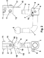
- Figure 2 shows profile and rear elevation views of the detached tow hook, with the ball extracted from the support.
- Figure 3 shows an internal profile view of the assembled tow hook, with the ball inserted in the support, detailing the position of the closure mechanism elements in the closure position.
- Figure 4 shows an internal profile view of the assembled tow hook, with the ball extracted from the support, detailing the position of the closure mechanism elements in the open position.
- the automatic vertically extractable tow hook that is the object of this invention is basically made up of, as can be seen in the plan attached, by two main elements: a vertically extractable ball (1) and a support (2) attached to the vehicle, both connected to each other by an automatic tapered catch (3).
- the vertically extractable ball (1) is made up of a central block (4) with a preferably square cross-section, although with rounded bottom edges, from which emerges horizontally a cylindrical section that, after a right-angled section, has a cross-section the diameter of which gradually reduces to end in a final spherical part (5) with the top end crowned by a straight surface, and used to hook the head to the trailer.
- a central block (4) emerges in a vertical direction the male part of the tapered catch (3) and which takes the shape of a tapered element ending in a cylindrical part provided with a partially cylindrical lateral recess (6).
- a marked longitudinal bevel (7) in the place corresponding to one of the edges, and which forms part of the tow hook's anti-rotation device.
- an additional safety and anti-theft mechanism (8) consisting of a horizontally moveable pin (9) operated by a key (10).
- the support (2) adopts the form of a block with a preferably quadrangular cross-section with the vertical edges preferably rounded and which is attached to the vehicle by a plurality of lateral threaded housings (11) designed to house the requisite assembly screws.
- a protuberance (12) At the bottom front part, in the place corresponding to the bottom front edge, projects a protuberance (12) with a triangular cross-section and which covers the aforementioned bottom front part of the support.
- This protuberance (12) is the other part of the anti-rotation device of the tow hook and possesses the corresponding size and proportions for fitting perfectly into the previously described longitudinal bevel (7) on the central part (4) of the ball (1), thereby preventing any type of rotation of the ball (1) on the horizontal plane in relation to the axis defined by the tapered catch (3), once inserted into the support (2).
- the bottom part of the support (2) is disposed with the opening (13) to a tapered housing (14) with the requisite dimensions to house in its male interior the tapered catch (3) so that the internal walls of the housing (14) are in close and complete contact with the internal walls of the male interior of the tapered catch (3) when the ball (1) is inserted into the support (2).
- the tow hook detachment lever At the bottom part of the support (2) has also been disposed the tow hook detachment lever (15).
- This lever has an axis of rotation (16) on one end, driving a vertically disposed boss (17) by means of another intermediate axis of rotation (18) and disposed with a through perforation (19) designed to house the horizontally moveable pin (9) operated by a key (10) disposed on the ball (1) as an additional safety and anti-theft mechanism (8), thereby locking the lever in the assembly position (lever up) and preventing it from being operated until it is released.
- the locking mechanism of the ball (1) is disposed in its entirety internally in the support (2), and is therefore always fixed to the vehicle.
- This mechanism consists of a locking cylinder (20), designed to be partially housed in the lateral recess (6) in the male part of the tapered catch (3) to prevent it from descending once it has been introduced, which is driven towards said lateral recess (6) by the top part of the boss (17) when it rises, which is disposed with a bevel (21) on its top part to cause this movement in a gentle manner.
- the boss (17) is driven upwards by a spring (22) after being released from its previous position by a horizontal needle (23), kept in its housing thanks to a spring (24) and which has been displaced as a result of its tip (25) being pushed by the conical catch (3) itself on being introduced in the housing (14) in which the tip (25) of the needle (23) projects out of, it also featuring also a release lever provided with a second key-operated safety closure mechanism that prevents its detachment.
- the unit is detached by opening the safety and anti-theft lock (8) with the key (10) so that the lever (15) can then be moved downwards, overcoming the force of the internal spring (22), thereby forcing the pin (17) to move down, thus causing the release of the locking roller (20) and therefore enabling the extraction of the ball (1).
- the needle (23) returns to its original position, with the head (25) projecting slightly in the interior of the housing (14), driven by its spring (24), locking at its bottom the boss (17) and the detachment lever (15), and leaving the support (2) ready for the ball (1) to be inserted again.
Landscapes
- Engineering & Computer Science (AREA)
- Transportation (AREA)
- Mechanical Engineering (AREA)
- Vehicle Step Arrangements And Article Storage (AREA)
- Vehicle Cleaning, Maintenance, Repair, Refitting, And Outriggers (AREA)
- Refuge Islands, Traffic Blockers, Or Guard Fence (AREA)
- Snaps, Bayonet Connections, Set Pins, And Snap Rings (AREA)
- Ladders (AREA)
- Catching Or Destruction (AREA)
- Forklifts And Lifting Vehicles (AREA)
Abstract
The present invention provides the main advantage of enabling a perfect fit between the ball and the support, free of play leading to looseness, with locking mechanisms that are fully incorporated into the support and which cannot be seen by the user when the ball is dismantled.
Description
- This present document relates, as its title suggests, to an automatic vertically extractable tow hook of the type used in motor cars or light industrial vehicles for hooking on to trailers, characterised in that it is formed by a vertically extractable ball with a tapered catch, provided with an anti-rotation mechanism, that is introduced into a support attached to the vehicle, being locked in place automatically by a locking roller that is inserted in a suitable housing in the conical catch driven by a pin and a spring released by a needle driven by the conical catch itself, it also having a release lever provided with a second safety closure mechanism with a key.
- There are many and varied types of tow hooks that are widely known at this time, particularly for motor cars and other light vehicles. The most simple and widely used are fixed tow hooks, which, directly or indirectly by an adaptor chassis, are attached to the supporting structure of the motor car. The problem with these tow hooks is that, as they project permanently from the tow hook ball, they change the aesthetic appearance of the vehicle, reducing or eliminating the safety function of the rear bumper, and causing injury to the user, oil stains, and damage to other vehicles during parking manoeuvres.
- To overcome these drawbacks, detachable tow hooks are widely known, in which the ball is only fitted when something needs to be towed, being removed for any other use, as a result of which the aforementioned problems are avoided. Many of these types of detachable tow hooks use manual mechanical fastenings by means of pins, bolts or rods to link the ball to the supporting structure of the vehicle. We can find examples of these types of tow hooks in Utility Model 9400991 "Extractable tow hook ball for vehicles" or in Patent 91107148 "Detachable tow hook", although the problem with this type of simple device is that the connection between the fixed part and the detachable part always has a certain amount of play that results from the fact that the tow hook is prone to tilt from side to side and rotate, and from mechanical wear that is accelerated by treatment, as well as causing a certain insecurity in the connection.
- Other types of hooks, such as the one described in Patent 9200569 "Extractable tow hook support for motor cars and vans" attempt to improve the connection between elements by using a bayonet-type hook with a triangular housing, but still have the drawback of insufficient fastening precision and play that increases over time, not to mention the fact that they do not have locks or safety mechanisms. Utility Model 286624 "Extractable tow hook" describes a bayonet-type tow hook with a rectangular housing with the drawback of play in the connection and insufficient stability achieved in the ball.
- Other devices are known such as the one disclosed in Patent 95202457 "Detachable tow hook device and procedure for its manufacture", which uses a dual-pin bayonet-type tow hook inserted manually not automatically, and which has the problem of a housing with a square cross-section prone to tilt from side to side and to create play, in addition to the fact that the housing of the ball remains permanently visible on the vehicle even after removing the ball.
- Some tow hooks, such as the one described in Utility Model 9200393 "Improved detachable tow hook device" attempt to address this situation by means of a cylindrical locking pin that is housable manually, not automatically, and which is locked in place by a manual shaft, the drawback being that is not concealed from the user and that it only has one safety mechanism.
- There are also tow hooks that cause the embedding of the ball automatically, such as the one claimed in Utility Model 9103763 "Tow hook device for trailers and similar attachments", which uses an automatic locking wedge with a spring, presenting the problems of being visible on the car, not being disposed with safety mechanisms and still being prone to tilt from side to side and rotate.
- Finally there are tow hooks such as that described in Patent 98107007 "Vehicle towing device with a tow hook with a detachable but automatically lockable ball, provided with a power point" based on a fitting groove with an automatic locking shaft, although there is still the problem of them being prone to wear due to tilting from side to side caused in the main by the small mechanical area of contact between the fixed part and the moving part.
- In an effort to address existing problems with regard to the problem presented by detachable tow hooks, the automatic vertically extractable tow hook that is the object of this invention has been devised, and which is essentially made up of two main components: a vertically extractable ball and a support attached to the vehicle, both connected to each other by an automatic tapered catch provided with an anti-rotation mechanism. The ball is fixed into place by inserting the tapered catch into a housing with a similar shape and size in the interior of the support and accessible by its bottom part, being locked in place automatically by a locking roller that is inserted in a suitable housing in the conical catch driven by a pin and a spring released by a needle driven by the conical catch itself, it also having a release lever provided with a second safety closure mechanism with a key to prevent it from being detached.
- The unit is detached by opening the safety lock with the key so that the lever can then be moved downwards, overcoming the force of the internal spring, thereby forcing the pin to move down, thus causing the release of the locking roller and therefore enabling the extraction of the ball. When the tapered element is removed from its housing the needle returns to its original position in the interior of the housing, driven by its spring, locking at its bottom the boss and the detachment lever, and leaving the support ready for the ball to be introduced again.
- The automatic vertically extractable tow hook presented herein provides numerous advantages over the systems currently available, the most important of them enabling a perfect fit between the ball and the support, without any play that might cause looseness, thanks to the self-centring tapered element that creates a perfect housing with soft guidance, with barely any effort, in the support.
- Another important advantage is that the support between the ball and the support itself is produced throughout the tapered element, without any play, thereby creating a greater area of contact between the ball and the support, and providing a more solid and stronger connection.
- Another important advantage is that the locking mechanisms are fully incorporated into the support, remaining concealed from the user when the ball is detached.
- As a result of the support remaining concealed, the bumpers are able to perform their safety function and, as the ball has been removed from the rear of the vehicle, they prevent injury to the user, oil stains, and damage to other vehicles during parking manoeuvres.
- We should not forget that the configuration of this tow hook enables an automated mechanisation manufacturing process and that there is no need for welding, which means that the material does not suffer, thereby creating greater durability and strength and also permitting the strictest manufacturing tolerances.
- As a result of its easy manufacture, and due to the mechanised manufacture without welding and with very little labour, production costs are significantly reduced.
- The undoubted advantage that the significantly reduced weight of the tow hook represents for the fitter and the user should be pointed out.
- Furthermore, it should be noted that its enclosed and precise structure does not require subsequent maintenance, and does not even need lubrication, thereby making it cleaner and easier to use.
- The considerable advantage of the greatly increased safety provided by the two built-in safety systems should also be pointed out, firstly by the closure mechanism itself and secondly by the key-operated pin, which also acts as an efficient anti-theft system.
- Finally, we must also highlight the fact that all the parts operate without causing wear to the materials or significant friction, looseness or play, thus reducing wear and increasing the operational life of the tow hook.
- In order to better understand the object of the present invention, a preferential practical embodiment of the automatic vertically extractable tow hook has been represented in the plan attached.
- In said plan figure 1 shows profile views and a rear elevation of the assembled tow hook, with the ball inserted in the support and the safety mechanism locked in place by the key.
- Figure 2 shows profile and rear elevation views of the detached tow hook, with the ball extracted from the support.
- Figure 3 shows an internal profile view of the assembled tow hook, with the ball inserted in the support, detailing the position of the closure mechanism elements in the closure position.
- Figure 4 shows an internal profile view of the assembled tow hook, with the ball extracted from the support, detailing the position of the closure mechanism elements in the open position.
- The automatic vertically extractable tow hook that is the object of this invention is basically made up of, as can be seen in the plan attached, by two main elements: a vertically extractable ball (1) and a support (2) attached to the vehicle, both connected to each other by an automatic tapered catch (3).
- The vertically extractable ball (1) is made up of a central block (4) with a preferably square cross-section, although with rounded bottom edges, from which emerges horizontally a cylindrical section that, after a right-angled section, has a cross-section the diameter of which gradually reduces to end in a final spherical part (5) with the top end crowned by a straight surface, and used to hook the head to the trailer. Out of the aforementioned central block (4) emerges in a vertical direction the male part of the tapered catch (3) and which takes the shape of a tapered element ending in a cylindrical part provided with a partially cylindrical lateral recess (6). At the top front part of the central block (1) and adjacent to the base of the tapered catch (3) can be found a marked longitudinal bevel (7) in the place corresponding to one of the edges, and which forms part of the tow hook's anti-rotation device. On one of the sides of the central block (4) can also be found horizontally disposed an additional safety and anti-theft mechanism (8) consisting of a horizontally moveable pin (9) operated by a key (10).
- The support (2) adopts the form of a block with a preferably quadrangular cross-section with the vertical edges preferably rounded and which is attached to the vehicle by a plurality of lateral threaded housings (11) designed to house the requisite assembly screws. At the bottom front part, in the place corresponding to the bottom front edge, projects a protuberance (12) with a triangular cross-section and which covers the aforementioned bottom front part of the support. This protuberance (12) is the other part of the anti-rotation device of the tow hook and possesses the corresponding size and proportions for fitting perfectly into the previously described longitudinal bevel (7) on the central part (4) of the ball (1), thereby preventing any type of rotation of the ball (1) on the horizontal plane in relation to the axis defined by the tapered catch (3), once inserted into the support (2). The bottom part of the support (2) is disposed with the opening (13) to a tapered housing (14) with the requisite dimensions to house in its male interior the tapered catch (3) so that the internal walls of the housing (14) are in close and complete contact with the internal walls of the male interior of the tapered catch (3) when the ball (1) is inserted into the support (2).
- At the bottom part of the support (2) has also been disposed the tow hook detachment lever (15). This lever has an axis of rotation (16) on one end, driving a vertically disposed boss (17) by means of another intermediate axis of rotation (18) and disposed with a through perforation (19) designed to house the horizontally moveable pin (9) operated by a key (10) disposed on the ball (1) as an additional safety and anti-theft mechanism (8), thereby locking the lever in the assembly position (lever up) and preventing it from being operated until it is released.
- The locking mechanism of the ball (1) is disposed in its entirety internally in the support (2), and is therefore always fixed to the vehicle. This mechanism consists of a locking cylinder (20), designed to be partially housed in the lateral recess (6) in the male part of the tapered catch (3) to prevent it from descending once it has been introduced, which is driven towards said lateral recess (6) by the top part of the boss (17) when it rises, which is disposed with a bevel (21) on its top part to cause this movement in a gentle manner. The boss (17) is driven upwards by a spring (22) after being released from its previous position by a horizontal needle (23), kept in its housing thanks to a spring (24) and which has been displaced as a result of its tip (25) being pushed by the conical catch (3) itself on being introduced in the housing (14) in which the tip (25) of the needle (23) projects out of, it also featuring also a release lever provided with a second key-operated safety closure mechanism that prevents its detachment. When the boss (17) rises it pulls the lever (15) to its closure position (top position) thanks to the axis (18). When the boss (17) reaches its upper stopper, its cylindrical wall prevents the horizontal displacement of the locking cylinder (20), which is firmly housed in the lateral recess (6) in the male part of the tapered catch (3). The additional safety and anti-theft mechanism (8) must then be activated to ensure the complete safety and locking of the tow hook.
- The unit is detached by opening the safety and anti-theft lock (8) with the key (10) so that the lever (15) can then be moved downwards, overcoming the force of the internal spring (22), thereby forcing the pin (17) to move down, thus causing the release of the locking roller (20) and therefore enabling the extraction of the ball (1). When the tapered element (3) is removed from its housing (14) the needle (23) returns to its original position, with the head (25) projecting slightly in the interior of the housing (14), driven by its spring (24), locking at its bottom the boss (17) and the detachment lever (15), and leaving the support (2) ready for the ball (1) to be inserted again.
- It was decided to omit a detailed description of the other particular features of the device being disclosed or of the components forming part of it, as it was felt that the rest of said particular features are not the object of any claims.
- Having described the nature of the present invention in sufficient detail, in addition to a means for putting it into practice, all that remains to be added is that its description is not restrictive, and that variations both in materials and forms and sizes can be made provided that said variations do not alter the essential nature of the characteristics claimed below.
Claims (8)
- Automatic vertically extractable tow hook of the type used in motor cars or light industrial vehicles for hooking on to trailers, characterised in that it is formed by a vertically extractable ball (1) and a support (2) attached to the vehicle, both connected together by an automatic tapered catch (3).
- Automatic vertically extractable tow hook according to the preceding claim wherein the vertically extractable ball (1) is made up of a central block (4) with a preferably square cross-section, although with rounded bottom edges, from which emerges horizontally a cylindrical section that, after a right-angled section, has a cross-section the diameter of which gradually reduces to end in a final spherical part (5) with the top end crowned by a straight surface, and used to hook the head to the trailer, emerging vertically out of the aforementioned central block (4) the male part of the tapered catch (3) and which takes the shape of a tapered element ending in a cylindrical part provided with a partially cylindrical lateral recess (6).
- Automatic vertically extractable tow hook according to the preceding claims wherein the ball (1) is disposed at the top front part of the central block (1) and adjacent to the base of the tapered catch (3) with a marked longitudinal bevel (7) in the place corresponding to one of the edges, and which forms part of the tow hook's anti-rotation device, also being found horizontally disposed on one of the sides of the central block (4) an additional safety and anti-theft mechanism (8) consisting of a horizontally moveable pin (9) operated by a key (10).
- Automatic vertically extractable tow hook according to the preceding claims wherein the support (2) adopts the form of a block with a preferably quadrangular cross-section with the vertical edges preferably rounded and which is attached to the vehicle by a plurality of lateral threaded housings (11) designed to house the requisite assembly screws, projecting at the bottom front part, in the place corresponding to the bottom front edge, a protuberance (12) with a triangular cross-section and which covers the aforementioned bottom front part of the support, and which is the other constituent part of the anti-rotation device of the tow hook and possesses the corresponding size and proportions for fitting perfectly into the previously described longitudinal bevel (7) on the central part (4) of the ball (1), thereby preventing any type of rotation of the ball (1) on the horizontal plane in relation to the axis defined by the tapered catch (3), once inserted into the support (2).
- Automatic vertically extractable tow hook according to the preceding claims wherein the bottom part of the support (2) is disposed with the opening (13) to a tapered housing (14) with the requisite dimensions to house in its male interior the tapered catch (3) so that the internal walls of the housing (14) are in close and complete contact with the internal walls of the male interior of the tapered catch (3) when the ball (1) is inserted into the support (2).
- Automatic vertically extractable tow hook according to the preceding claims wherein at the bottom part of the support (2) has also been disposed the tow hook detachment lever (15), being disposed with an axis of rotation (16) on one end, driving a vertically disposed boss (17) by means of another intermediate axis of rotation (18) and also being disposed with a through perforation (19) designed to house the horizontally moveable pin (9) operated by a key (10) disposed on the ball (1) as an additional safety and anti-theft mechanism (8), thereby locking the lever in the assembly position (lever up) and preventing it from being operated until it is released.
- Automatic vertically extractable tow hook according to the preceding claims wherein the locking mechanism of the ball (1) is disposed in its entirety internally in the support (2), and is therefore always fixed to the vehicle, this mechanism consisting of a locking cylinder (20), designed to be partially housed in the lateral recess (6) in the male part of the tapered catch (3) to prevent it from descending once it has been introduced, which is driven towards said lateral recess (6) by the top part of the boss (17) when it rises, which is disposed with a bevel (21) on its top part to cause this movement in a gentle manner, the boss (17) being driven upwards by a spring (22) after being released from its previous position by a horizontal needle (23), kept in its housing thanks to a spring (24) and which has been displaced as a result of its tip (25) being pushed by the conical catch (3) itself on being introduced in the housing (14) in which the tip (25) of the needle (23) projects out of, the boss (17), when it rises, pulling the lever (15) to its closure position (top position) thanks to the axis (18), its cylindrical wall preventing, when the boss (17) reaches its upper stopper, the horizontal displacement of the locking cylinder (20), which is firmly housed in the lateral recess (6) in the male part of the tapered catch (3), the additional safety and anti-theft device (8) then being activated.
- Automatic vertically extractable tow hook according to the preceding claims wherein the detachment of the unit involves opening the safety and anti-theft lock (8) with the key (10) so that the lever (15) can then be moved downwards, overcoming the force of the internal spring (22), thereby forcing the pin (17) to move down, thus causing the release of the locking roller (20) and therefore enabling the extraction of the ball (1), so that then, when the tapered element (3) is removed from its housing (14) the needle (23) returns to its original position, with the head (25) projecting slightly in the interior of the housing (14), driven by its spring (24), locking at its bottom the boss (17) and the detachment lever (15), and leaving the support (2) ready for the ball (1) to be introduced again.
Applications Claiming Priority (1)
| Application Number | Priority Date | Filing Date | Title |
|---|---|---|---|
| ES200602120A ES2263403B1 (en) | 2006-08-01 | 2006-08-01 | AUTOMATIC VERTICAL EXTRACTION HITCH. |
Publications (2)
| Publication Number | Publication Date |
|---|---|
| EP1884378A1 true EP1884378A1 (en) | 2008-02-06 |
| EP1884378B1 EP1884378B1 (en) | 2009-08-12 |
Family
ID=37810162
Family Applications (1)
| Application Number | Title | Priority Date | Filing Date |
|---|---|---|---|
| EP07006033A Active EP1884378B1 (en) | 2006-08-01 | 2007-03-23 | Automatic vertically extractable tow hook |
Country Status (4)
| Country | Link |
|---|---|
| EP (1) | EP1884378B1 (en) |
| AT (1) | ATE439262T1 (en) |
| DE (1) | DE602007001922D1 (en) |
| ES (2) | ES2263403B1 (en) |
Cited By (5)
| Publication number | Priority date | Publication date | Assignee | Title |
|---|---|---|---|---|
| EP2236322A1 (en) * | 2009-03-31 | 2010-10-06 | Dirk Visser | Electronically controlled tow hitch assembly |
| GB2575130A (en) * | 2018-06-27 | 2020-01-01 | Lafuente Hermanos S Sa | Demountable hitching device for towing by vehicles, and associated unlocking device |
| CN113147286A (en) * | 2021-05-10 | 2021-07-23 | 精诚工科汽车系统有限公司 | Towing devices for vehicles and vehicles |
| CN116373512A (en) * | 2023-03-24 | 2023-07-04 | 浙江致优汽车科技有限公司 | trailer coupler |
| CN116437604A (en) * | 2023-04-11 | 2023-07-14 | 宁波甬科声学技术有限公司 | Mounting structure for precision data acquisition control board |
Families Citing this family (1)
| Publication number | Priority date | Publication date | Assignee | Title |
|---|---|---|---|---|
| ES2534961B1 (en) * | 2013-10-31 | 2016-02-19 | Enganches Y Remolques Aragón, S.L. | Automatic vertical pull hitch |
Citations (9)
| Publication number | Priority date | Publication date | Assignee | Title |
|---|---|---|---|---|
| DE3416631A1 (en) * | 1984-05-05 | 1985-11-07 | Walter Dr.-Ing. 5100 Aachen Jürgens | Trailer coupling |
| EP0160934A2 (en) * | 1984-05-05 | 1985-11-13 | Walter Dr. Ing. Jürgens | Removable trailer hitch for a motor vehicle |
| ES286624U (en) | 1984-05-10 | 1985-12-01 | Fiat Auto S.P.A. | Removable trailer hitch (Machine-translation by Google Translate, not legally binding) |
| EP0212322A2 (en) * | 1985-08-09 | 1987-03-04 | PEKA-Fahrzeugbau GmbH & Co. KG | Removable trailer coupling |
| DE3601505A1 (en) * | 1986-01-20 | 1987-07-23 | Juergens Walter | TOWING DEVICE |
| ES1019590U (en) | 1991-12-13 | 1992-04-01 | Sanchis Font Gonzalo | Hook-up device for trailers and the like. |
| ES1020185U (en) | 1992-02-10 | 1992-06-01 | Moreno Remondo Adolfo | Detachable device for improved trailer hitch. (Machine-translation by Google Translate, not legally binding) |
| ES2052435A2 (en) | 1991-03-28 | 1994-07-01 | Truetzschler & Co | Apparatus for cleaning and opening fibre material |
| ES1027695U (en) | 1994-04-13 | 1994-09-16 | Lafuente Hermanos S Sa | Removable ball hitch for vehicles. (Machine-translation by Google Translate, not legally binding) |
Family Cites Families (3)
| Publication number | Priority date | Publication date | Assignee | Title |
|---|---|---|---|---|
| DE3238094A1 (en) * | 1982-10-14 | 1984-04-19 | Oris-Metallbau KG Hans Riehle, 7141 Möglingen | TOWING DEVICE FOR PARTICULAR CARS IN PARTICULAR |
| DE3634385A1 (en) * | 1986-10-09 | 1988-04-21 | Juergens Walter | TOWING DEVICE |
| ES1046535Y (en) * | 2000-06-13 | 2001-06-01 | Talleres Cintra S L | REMOVABLE HITCH FOR VEHICLES. |
-
2006
- 2006-08-01 ES ES200602120A patent/ES2263403B1/en not_active Expired - Fee Related
-
2007
- 2007-03-23 DE DE602007001922T patent/DE602007001922D1/en active Active
- 2007-03-23 EP EP07006033A patent/EP1884378B1/en active Active
- 2007-03-23 ES ES07006033T patent/ES2331757T3/en active Active
- 2007-03-23 AT AT07006033T patent/ATE439262T1/en not_active IP Right Cessation
Patent Citations (9)
| Publication number | Priority date | Publication date | Assignee | Title |
|---|---|---|---|---|
| DE3416631A1 (en) * | 1984-05-05 | 1985-11-07 | Walter Dr.-Ing. 5100 Aachen Jürgens | Trailer coupling |
| EP0160934A2 (en) * | 1984-05-05 | 1985-11-13 | Walter Dr. Ing. Jürgens | Removable trailer hitch for a motor vehicle |
| ES286624U (en) | 1984-05-10 | 1985-12-01 | Fiat Auto S.P.A. | Removable trailer hitch (Machine-translation by Google Translate, not legally binding) |
| EP0212322A2 (en) * | 1985-08-09 | 1987-03-04 | PEKA-Fahrzeugbau GmbH & Co. KG | Removable trailer coupling |
| DE3601505A1 (en) * | 1986-01-20 | 1987-07-23 | Juergens Walter | TOWING DEVICE |
| ES2052435A2 (en) | 1991-03-28 | 1994-07-01 | Truetzschler & Co | Apparatus for cleaning and opening fibre material |
| ES1019590U (en) | 1991-12-13 | 1992-04-01 | Sanchis Font Gonzalo | Hook-up device for trailers and the like. |
| ES1020185U (en) | 1992-02-10 | 1992-06-01 | Moreno Remondo Adolfo | Detachable device for improved trailer hitch. (Machine-translation by Google Translate, not legally binding) |
| ES1027695U (en) | 1994-04-13 | 1994-09-16 | Lafuente Hermanos S Sa | Removable ball hitch for vehicles. (Machine-translation by Google Translate, not legally binding) |
Cited By (6)
| Publication number | Priority date | Publication date | Assignee | Title |
|---|---|---|---|---|
| EP2236322A1 (en) * | 2009-03-31 | 2010-10-06 | Dirk Visser | Electronically controlled tow hitch assembly |
| GB2575130A (en) * | 2018-06-27 | 2020-01-01 | Lafuente Hermanos S Sa | Demountable hitching device for towing by vehicles, and associated unlocking device |
| CN113147286A (en) * | 2021-05-10 | 2021-07-23 | 精诚工科汽车系统有限公司 | Towing devices for vehicles and vehicles |
| CN116373512A (en) * | 2023-03-24 | 2023-07-04 | 浙江致优汽车科技有限公司 | trailer coupler |
| CN116437604A (en) * | 2023-04-11 | 2023-07-14 | 宁波甬科声学技术有限公司 | Mounting structure for precision data acquisition control board |
| CN116437604B (en) * | 2023-04-11 | 2023-11-03 | 宁波甬科声学技术有限公司 | Mounting structure for precision data acquisition control board |
Also Published As
| Publication number | Publication date |
|---|---|
| ES2263403B1 (en) | 2007-12-01 |
| ATE439262T1 (en) | 2009-08-15 |
| ES2331757T3 (en) | 2010-01-14 |
| EP1884378B1 (en) | 2009-08-12 |
| DE602007001922D1 (en) | 2009-09-24 |
| ES2263403A1 (en) | 2006-12-01 |
Similar Documents
| Publication | Publication Date | Title |
|---|---|---|
| EP1884378A1 (en) | Automatic vertically extractable tow hook | |
| US8500102B2 (en) | Retractable jack foot | |
| DE202016104156U1 (en) | Device for securing the removal of an accumulator | |
| DE202018101003U1 (en) | Removable tailgate with locking joint | |
| DE202020005815U1 (en) | Wheel holder and load carrier attachment device for a vehicle | |
| NL2021585B1 (en) | DETACHABLE COUPLING DEVICE FOR TRAILERS ON VEHICLES AND ASSOCIATED RELEASE DEVICE | |
| EP2130698B1 (en) | Tow bar | |
| CN101607533A (en) | Built-in double pin locking device for car seat slide rail | |
| DE202013103194U1 (en) | A support leg concealment mechanism | |
| CN110952844A (en) | Latch lock and vehicle using same | |
| DE202013104598U1 (en) | Device for the detachable attachment of functional parts | |
| US20090026737A1 (en) | Heavy duty lock hinge gate | |
| CN117246082B (en) | Tow hook assembly for vehicles and vehicles | |
| EP2130694A1 (en) | Tow bar | |
| EP2130697A1 (en) | Tow bar | |
| CN219706579U (en) | trailer coupler | |
| EP2623345B1 (en) | Towing hook arrangement and a method for displacing a towing hook of a towing hook arrangement | |
| EP2946950A1 (en) | socket assembly | |
| KR101341743B1 (en) | Semi-automatic drawbar for two vehicle | |
| CN223904818U (en) | Trailer traction reinforcing structure | |
| CN220604881U (en) | Quick-release lock for surfboard battery | |
| US3321181A (en) | Vehicle tongue with an improved, lever-operated jack | |
| CN205632225U (en) | Hide telescopic link of safe hammer | |
| CN223100627U (en) | Automobile exterior trim part mounting structure | |
| CN114248862B (en) | Lockable vehicle goods shelf |
Legal Events
| Date | Code | Title | Description |
|---|---|---|---|
| PUAI | Public reference made under article 153(3) epc to a published international application that has entered the european phase |
Free format text: ORIGINAL CODE: 0009012 |
|
| AK | Designated contracting states |
Kind code of ref document: A1 Designated state(s): AT BE BG CH CY CZ DE DK EE ES FI FR GB GR HU IE IS IT LI LT LU LV MC MT NL PL PT RO SE SI SK TR |
|
| AX | Request for extension of the european patent |
Extension state: AL BA HR MK YU |
|
| 17P | Request for examination filed |
Effective date: 20080527 |
|
| 17Q | First examination report despatched |
Effective date: 20080710 |
|
| AKX | Designation fees paid |
Designated state(s): AT BE BG CH CY CZ DE DK EE ES FI FR GB GR HU IE IS IT LI LT LU LV MC MT NL PL PT RO SE SI SK TR |
|
| GRAP | Despatch of communication of intention to grant a patent |
Free format text: ORIGINAL CODE: EPIDOSNIGR1 |
|
| RIN1 | Information on inventor provided before grant (corrected) |
Inventor name: BENITO MONREAL, FERNANDO Inventor name: NARBON BASELGA, ANTONIO Inventor name: LEGASA PEREZ, FEDERICO |
|
| GRAS | Grant fee paid |
Free format text: ORIGINAL CODE: EPIDOSNIGR3 |
|
| GRAA | (expected) grant |
Free format text: ORIGINAL CODE: 0009210 |
|
| AK | Designated contracting states |
Kind code of ref document: B1 Designated state(s): AT BE BG CH CY CZ DE DK EE ES FI FR GB GR HU IE IS IT LI LT LU LV MC MT NL PL PT RO SE SI SK TR |
|
| REG | Reference to a national code |
Ref country code: GB Ref legal event code: FG4D |
|
| REG | Reference to a national code |
Ref country code: CH Ref legal event code: EP |
|
| REG | Reference to a national code |
Ref country code: IE Ref legal event code: FG4D |
|
| REF | Corresponds to: |
Ref document number: 602007001922 Country of ref document: DE Date of ref document: 20090924 Kind code of ref document: P |
|
| REG | Reference to a national code |
Ref country code: ES Ref legal event code: FG2A Ref document number: 2331757 Country of ref document: ES Kind code of ref document: T3 |
|
| LTIE | Lt: invalidation of european patent or patent extension |
Effective date: 20090812 |
|
| PG25 | Lapsed in a contracting state [announced via postgrant information from national office to epo] |
Ref country code: LT Free format text: LAPSE BECAUSE OF FAILURE TO SUBMIT A TRANSLATION OF THE DESCRIPTION OR TO PAY THE FEE WITHIN THE PRESCRIBED TIME-LIMIT Effective date: 20090812 Ref country code: AT Free format text: LAPSE BECAUSE OF FAILURE TO SUBMIT A TRANSLATION OF THE DESCRIPTION OR TO PAY THE FEE WITHIN THE PRESCRIBED TIME-LIMIT Effective date: 20090812 Ref country code: FI Free format text: LAPSE BECAUSE OF FAILURE TO SUBMIT A TRANSLATION OF THE DESCRIPTION OR TO PAY THE FEE WITHIN THE PRESCRIBED TIME-LIMIT Effective date: 20090812 Ref country code: IS Free format text: LAPSE BECAUSE OF FAILURE TO SUBMIT A TRANSLATION OF THE DESCRIPTION OR TO PAY THE FEE WITHIN THE PRESCRIBED TIME-LIMIT Effective date: 20091212 Ref country code: SE Free format text: LAPSE BECAUSE OF FAILURE TO SUBMIT A TRANSLATION OF THE DESCRIPTION OR TO PAY THE FEE WITHIN THE PRESCRIBED TIME-LIMIT Effective date: 20090812 |
|
| NLV1 | Nl: lapsed or annulled due to failure to fulfill the requirements of art. 29p and 29m of the patents act | ||
| PG25 | Lapsed in a contracting state [announced via postgrant information from national office to epo] |
Ref country code: LV Free format text: LAPSE BECAUSE OF FAILURE TO SUBMIT A TRANSLATION OF THE DESCRIPTION OR TO PAY THE FEE WITHIN THE PRESCRIBED TIME-LIMIT Effective date: 20090812 Ref country code: NL Free format text: LAPSE BECAUSE OF FAILURE TO SUBMIT A TRANSLATION OF THE DESCRIPTION OR TO PAY THE FEE WITHIN THE PRESCRIBED TIME-LIMIT Effective date: 20090812 Ref country code: SI Free format text: LAPSE BECAUSE OF FAILURE TO SUBMIT A TRANSLATION OF THE DESCRIPTION OR TO PAY THE FEE WITHIN THE PRESCRIBED TIME-LIMIT Effective date: 20090812 Ref country code: PL Free format text: LAPSE BECAUSE OF FAILURE TO SUBMIT A TRANSLATION OF THE DESCRIPTION OR TO PAY THE FEE WITHIN THE PRESCRIBED TIME-LIMIT Effective date: 20090812 |
|
| PG25 | Lapsed in a contracting state [announced via postgrant information from national office to epo] |
Ref country code: BG Free format text: LAPSE BECAUSE OF FAILURE TO SUBMIT A TRANSLATION OF THE DESCRIPTION OR TO PAY THE FEE WITHIN THE PRESCRIBED TIME-LIMIT Effective date: 20091112 Ref country code: PT Free format text: LAPSE BECAUSE OF FAILURE TO SUBMIT A TRANSLATION OF THE DESCRIPTION OR TO PAY THE FEE WITHIN THE PRESCRIBED TIME-LIMIT Effective date: 20091212 |
|
| PG25 | Lapsed in a contracting state [announced via postgrant information from national office to epo] |
Ref country code: CZ Free format text: LAPSE BECAUSE OF FAILURE TO SUBMIT A TRANSLATION OF THE DESCRIPTION OR TO PAY THE FEE WITHIN THE PRESCRIBED TIME-LIMIT Effective date: 20090812 Ref country code: RO Free format text: LAPSE BECAUSE OF FAILURE TO SUBMIT A TRANSLATION OF THE DESCRIPTION OR TO PAY THE FEE WITHIN THE PRESCRIBED TIME-LIMIT Effective date: 20090812 Ref country code: DK Free format text: LAPSE BECAUSE OF FAILURE TO SUBMIT A TRANSLATION OF THE DESCRIPTION OR TO PAY THE FEE WITHIN THE PRESCRIBED TIME-LIMIT Effective date: 20090812 Ref country code: EE Free format text: LAPSE BECAUSE OF FAILURE TO SUBMIT A TRANSLATION OF THE DESCRIPTION OR TO PAY THE FEE WITHIN THE PRESCRIBED TIME-LIMIT Effective date: 20090812 |
|
| PG25 | Lapsed in a contracting state [announced via postgrant information from national office to epo] |
Ref country code: SK Free format text: LAPSE BECAUSE OF FAILURE TO SUBMIT A TRANSLATION OF THE DESCRIPTION OR TO PAY THE FEE WITHIN THE PRESCRIBED TIME-LIMIT Effective date: 20090812 |
|
| PLBE | No opposition filed within time limit |
Free format text: ORIGINAL CODE: 0009261 |
|
| STAA | Information on the status of an ep patent application or granted ep patent |
Free format text: STATUS: NO OPPOSITION FILED WITHIN TIME LIMIT |
|
| PG25 | Lapsed in a contracting state [announced via postgrant information from national office to epo] |
Ref country code: BE Free format text: LAPSE BECAUSE OF FAILURE TO SUBMIT A TRANSLATION OF THE DESCRIPTION OR TO PAY THE FEE WITHIN THE PRESCRIBED TIME-LIMIT Effective date: 20090812 |
|
| 26N | No opposition filed |
Effective date: 20100517 |
|
| PGFP | Annual fee paid to national office [announced via postgrant information from national office to epo] |
Ref country code: ES Payment date: 20100421 Year of fee payment: 4 |
|
| PGFP | Annual fee paid to national office [announced via postgrant information from national office to epo] |
Ref country code: DE Payment date: 20100429 Year of fee payment: 4 |
|
| PG25 | Lapsed in a contracting state [announced via postgrant information from national office to epo] |
Ref country code: MC Free format text: LAPSE BECAUSE OF NON-PAYMENT OF DUE FEES Effective date: 20100331 Ref country code: GR Free format text: LAPSE BECAUSE OF FAILURE TO SUBMIT A TRANSLATION OF THE DESCRIPTION OR TO PAY THE FEE WITHIN THE PRESCRIBED TIME-LIMIT Effective date: 20091113 |
|
| REG | Reference to a national code |
Ref country code: FR Ref legal event code: ST Effective date: 20101130 |
|
| PG25 | Lapsed in a contracting state [announced via postgrant information from national office to epo] |
Ref country code: FR Free format text: LAPSE BECAUSE OF NON-PAYMENT OF DUE FEES Effective date: 20100331 Ref country code: IE Free format text: LAPSE BECAUSE OF NON-PAYMENT OF DUE FEES Effective date: 20100323 |
|
| PG25 | Lapsed in a contracting state [announced via postgrant information from national office to epo] |
Ref country code: MT Free format text: LAPSE BECAUSE OF FAILURE TO SUBMIT A TRANSLATION OF THE DESCRIPTION OR TO PAY THE FEE WITHIN THE PRESCRIBED TIME-LIMIT Effective date: 20090812 |
|
| REG | Reference to a national code |
Ref country code: CH Ref legal event code: PL |
|
| GBPC | Gb: european patent ceased through non-payment of renewal fee |
Effective date: 20110323 |
|
| PGFP | Annual fee paid to national office [announced via postgrant information from national office to epo] |
Ref country code: IT Payment date: 20100331 Year of fee payment: 4 |
|
| PG25 | Lapsed in a contracting state [announced via postgrant information from national office to epo] |
Ref country code: CH Free format text: LAPSE BECAUSE OF NON-PAYMENT OF DUE FEES Effective date: 20110331 Ref country code: DE Free format text: LAPSE BECAUSE OF NON-PAYMENT OF DUE FEES Effective date: 20111001 Ref country code: LI Free format text: LAPSE BECAUSE OF NON-PAYMENT OF DUE FEES Effective date: 20110331 |
|
| PG25 | Lapsed in a contracting state [announced via postgrant information from national office to epo] |
Ref country code: GB Free format text: LAPSE BECAUSE OF NON-PAYMENT OF DUE FEES Effective date: 20110323 |
|
| REG | Reference to a national code |
Ref country code: ES Ref legal event code: FD2A Effective date: 20120424 |
|
| REG | Reference to a national code |
Ref country code: DE Ref legal event code: R119 Ref document number: 602007001922 Country of ref document: DE Effective date: 20111001 |
|
| PG25 | Lapsed in a contracting state [announced via postgrant information from national office to epo] |
Ref country code: ES Free format text: LAPSE BECAUSE OF NON-PAYMENT OF DUE FEES Effective date: 20110324 |
|
| PG25 | Lapsed in a contracting state [announced via postgrant information from national office to epo] |
Ref country code: CY Free format text: LAPSE BECAUSE OF FAILURE TO SUBMIT A TRANSLATION OF THE DESCRIPTION OR TO PAY THE FEE WITHIN THE PRESCRIBED TIME-LIMIT Effective date: 20090812 |
|
| PG25 | Lapsed in a contracting state [announced via postgrant information from national office to epo] |
Ref country code: HU Free format text: LAPSE BECAUSE OF FAILURE TO SUBMIT A TRANSLATION OF THE DESCRIPTION OR TO PAY THE FEE WITHIN THE PRESCRIBED TIME-LIMIT Effective date: 20100213 Ref country code: LU Free format text: LAPSE BECAUSE OF NON-PAYMENT OF DUE FEES Effective date: 20100323 |
|
| PG25 | Lapsed in a contracting state [announced via postgrant information from national office to epo] |
Ref country code: TR Free format text: LAPSE BECAUSE OF FAILURE TO SUBMIT A TRANSLATION OF THE DESCRIPTION OR TO PAY THE FEE WITHIN THE PRESCRIBED TIME-LIMIT Effective date: 20090812 |