EP1884122B1 - Trennungspunkte in einem telekommunikationssystem - Google Patents
Trennungspunkte in einem telekommunikationssystem Download PDFInfo
- Publication number
- EP1884122B1 EP1884122B1 EP06753656A EP06753656A EP1884122B1 EP 1884122 B1 EP1884122 B1 EP 1884122B1 EP 06753656 A EP06753656 A EP 06753656A EP 06753656 A EP06753656 A EP 06753656A EP 1884122 B1 EP1884122 B1 EP 1884122B1
- Authority
- EP
- European Patent Office
- Prior art keywords
- connector block
- distribution frame
- signal path
- state
- connector
- Prior art date
- Legal status (The legal status is an assumption and is not a legal conclusion. Google has not performed a legal analysis and makes no representation as to the accuracy of the status listed.)
- Not-in-force
Links
Images


Classifications
-
- H—ELECTRICITY
- H04—ELECTRIC COMMUNICATION TECHNIQUE
- H04Q—SELECTING
- H04Q1/00—Details of selecting apparatus or arrangements
- H04Q1/02—Constructional details
- H04Q1/14—Distribution frames
- H04Q1/142—Terminal blocks for distribution frames
-
- H—ELECTRICITY
- H01—ELECTRIC ELEMENTS
- H01R—ELECTRICALLY-CONDUCTIVE CONNECTIONS; STRUCTURAL ASSOCIATIONS OF A PLURALITY OF MUTUALLY-INSULATED ELECTRICAL CONNECTING ELEMENTS; COUPLING DEVICES; CURRENT COLLECTORS
- H01R13/00—Details of coupling devices of the kinds covered by groups H01R12/70 or H01R24/00 - H01R33/00
- H01R13/66—Structural association with built-in electrical component
- H01R13/70—Structural association with built-in electrical component with built-in switch
- H01R13/703—Structural association with built-in electrical component with built-in switch operated by engagement or disengagement of coupling parts, e.g. dual-continuity coupling part
- H01R13/7036—Structural association with built-in electrical component with built-in switch operated by engagement or disengagement of coupling parts, e.g. dual-continuity coupling part the switch being in series with coupling part, e.g. dead coupling, explosion proof coupling
- H01R13/7038—Structural association with built-in electrical component with built-in switch operated by engagement or disengagement of coupling parts, e.g. dual-continuity coupling part the switch being in series with coupling part, e.g. dead coupling, explosion proof coupling making use of a remote controlled switch, e.g. relais, solid state switch activated by the engagement of the coupling parts
-
- H—ELECTRICITY
- H04—ELECTRIC COMMUNICATION TECHNIQUE
- H04B—TRANSMISSION
- H04B3/00—Line transmission systems
- H04B3/02—Details
- H04B3/20—Reducing echo effects or singing; Opening or closing transmitting path; Conditioning for transmission in one direction or the other
-
- H—ELECTRICITY
- H04—ELECTRIC COMMUNICATION TECHNIQUE
- H04Q—SELECTING
- H04Q1/00—Details of selecting apparatus or arrangements
- H04Q1/02—Constructional details
- H04Q1/14—Distribution frames
- H04Q1/144—Plugs used in distribution frames
-
- H—ELECTRICITY
- H01—ELECTRIC ELEMENTS
- H01R—ELECTRICALLY-CONDUCTIVE CONNECTIONS; STRUCTURAL ASSOCIATIONS OF A PLURALITY OF MUTUALLY-INSULATED ELECTRICAL CONNECTING ELEMENTS; COUPLING DEVICES; CURRENT COLLECTORS
- H01R2201/00—Connectors or connections adapted for particular applications
- H01R2201/16—Connectors or connections adapted for particular applications for telephony
-
- H—ELECTRICITY
- H01—ELECTRIC ELEMENTS
- H01R—ELECTRICALLY-CONDUCTIVE CONNECTIONS; STRUCTURAL ASSOCIATIONS OF A PLURALITY OF MUTUALLY-INSULATED ELECTRICAL CONNECTING ELEMENTS; COUPLING DEVICES; CURRENT COLLECTORS
- H01R29/00—Coupling parts for selective co-operation with a counterpart in different ways to establish different circuits, e.g. for voltage selection, for series-parallel selection, programmable connectors
Definitions
- the present invention relates to new or additional services, e.g. xDSL services such as ADSL, in a telecommunication system, e.g. a telephone system especially to methods of interconnection and to interconnection points for connecting telecommunication services.
- a telecommunication system e.g. a telephone system especially to methods of interconnection and to interconnection points for connecting telecommunication services.
- the present invention particularly relates to the provision of disconnection points in a telecommunication system.
- POTS plain old telephone service
- CO central office
- PSTN public switched telephone network
- ADSL asymmetric digital subscriber line
- the ADSL service supports uplink traffic having a lower bit rate than the downlink traffic.
- the ADSL traffic traverses the same copper wire pair traditionally used as the telephone line in the POTS.
- a general reference to xDSL telecommunication systems is: " ADSL & DSL Technologies, 2nd Ed., W. J. Goralski, Osbourne/McGraw Hill, 2002 .
- telecommunication centrals are being upgraded on the one hand to provide extra DSL services and secondly to save space by replacing old electronic devices, e.g. a legacy switch, by new switches/electronic devices (e.g. MSAN - see Fig. 1 ). From service level point of view it is often unacceptable to bring the new switch or equivalent electronic device (e.g. MSAN) in service from day one and directly physically decouple the old switch or electronic device. Cutting copper wires to obtain such replacement is often not accepted as an option, because cabling cannot always be cut near the relevant connector block due to space restrictions and accessibility. Then cutting the copper wires creates a stub effect. Hence there is a need for a disconnection point.
- US 5,991,140 describes re-wiring in a terminal where a POTS channel unit and the ADSL channel unit are deployed, the re-wiring being realized by connecting the POTS channel unit to the ADSL channel unit using a patch cord.
- the patch cord includes a circuit for protecting equipment including the channel units in the terminal from abnormal electrical conditions, e.g. an over-voltage condition.
- WO 2004/032563 shows a plug-in module for test access by obtaining a metal port.
- To obtain a metal port for test purposes requires that the telecommunications provided by the distribution frame are interrupted so that testing of the lines can be carried out.
- An object of the present invention relates to the provision of new or additional services, e.g. xDSL services such as ADSL, in a telecommunication system, e.g. a telephone system especially to improved methods of interconnection and to interconnection points for connecting telecommunication services.
- the present invention provides a distribution frame with at least one connector block, the connector block being mechanically connectable with the distribution frame to thereby cooperate electrically with the distribution frame to provide a first signal path between a first side and a second side of the distribution frame, the connector block having connector means for connecting a signal cable for an additional telecommunication service and being provided with a communication path for providing a second signal path between the signal cable and the second side of the distribution frame.
- the connector block can have a disconnection unit for providing two states of the connector block, in the first state at least the first signal path is provided and in the second state at least the second signal path is provided.
- the second signal path is not provided and/or in the second state the first signal path is not provided.
- the disconnection unit can also provide for two states of the connector block, in the first state at least the second signal path is provided and in the second state at least the first signal path is provided.
- the first signal path is not provided and/or in the second state the second signal path is not provided.
- the disconnection unit can be switched from the first sate to the second state remotely, for example the disconnection unit comprises a disconnection device and a coupler, the coupler providing a connection to the distribution frame, e.g. when the connector block is inserted therein, the disconnection device being remotely activatable or activatable only local to the distribution frame.
- the locally activatable disconnection device can be a switch, a relay, a jumper cable or a connector or for example the remotely activatable disconnection device can be a switch or a relay.
- the connector block can further comprise a test access point.
- the second signal path can be used for a DSL service, e.g. ADSL and can be a permanent or semi-permanent connection.
- the disconnection unit can be adapted to provide the first and the second signal paths in parallel in the second state.
- the disconnection unit can be adapted to provide the first and the second signal paths in parallel in the first state.
- the first signal path and/or second signal path can be used for a telephone service.
- the telephone service need not be only a test access.
- the present invention also provides a connector block for use with a distribution frame, the connector block having means for connecting the connector block with the distribution frame to thereby cooperate electrically with the distribution frame to provide a first signal path between a first side and a second side of the distribution frame, the connector block having connector means for connecting a signal cable for an additional telecommunication service and being provided with a communication path for providing a second signal path between the signal cable and the second side of the distribution frame.
- the connector block can also have a disconnection unit for providing two states of the connector block, in the first state at least the first signal path is provided and in the second state at least the second signal path is provided. Optionally, in the first state the second signal path is not provided and/or optionally, in the second state the first signal path is not provided.
- the disconnection unit can provide two states of the connector block, in the first state at least the second signal path is provided and in the second state at least the first signal path is provided.
- the first state the first signal path is not provided.
- the second state the second signal path is not provided.
- the disconnection unit can be switched from the first sate to the second state remotely, for example.
- the disconnection unit can comprise a disconnection device and a coupler, the coupler providing a connection to the distribution frame when the connector block is connected thereto, the disconnection device being remotely activatable or activatable only locally to the connector block.
- the locally activatable disconnection device can be a switch, a relay, a jumper cable or a connector.
- the remotely activatable disconnection device can be a switch or a relay.
- the disconnection unit can be adapted to provide the first and the second signal paths in parallel in the first or the second state.
- Any connector block of the present invention may further comprise a test access point.
- the present invention provides a method of connecting an additional service to a distribution frame with at least one connector block, the connector block being mechanically connectable with the distribution frame to thereby cooperate electrically with the distribution frame to provide a first signal path between a first side and a second side of the distribution frame, the method comprising: connecting a signal cable for an additional telecommunication service to the connector block to thereby provide a second signal path between the signal cable and the second side of the distribution frame.
- the connector block can have a disconnection unit for providing two states of the connector block, in the first state at least the first signal path is provided and in the second state at least the second signal path is provided, the method further comprising changing the connector block from the first to the second state.
- the disconnection unit can provide two states of the connector block, in the first state the at least the second signal path is provided and in the second state at least the first signal path is provided, the method further comprising changing the connector block from the first to the second state or vice versa.
- the changing can be made locally to the connector block or remotely therefrom.
- the second signal path can be for a DSL service.
- the first signal path can be for a telephone service, e.g. POTS.
- the second signal path need not just be a test access.
- the present invention provides a disconnect point for upgrading and/or providing an additional service, e.g. a DSL service, in a telecommunications network, e.g. a POTS.
- An advantage of the present invention is that space is saved by replacing old electronic devices, e.g. a legacy switch, by new switches or electronic devices (e.g. MSAN). From service level point of view it is often unacceptable to bring the new switch or equivalent electronic device (e.g. MSAN) into service from day one and directly physically decouple the old switch or electronic device. Instead, it can be done in phases and additionally the transition between phases can be established so that down time is minimized.
- the present invention allows: Phase 1 for coupling the new switch/electronic device (e.g.
- Phase 2 comprises switching off the old switch (e.g. legacy switch), and bringing the new electronic device into service. It is possible to switch back to the legacy device. This gives the advantage to bring the old switch back in service in case problems occur in the transition period.
- the third phase is to physically disconnect the old electronic device by means of a mechanical or electrical disconnect at the connector block level which effectively cuts the copper wire interconnection. After this step the old equipment and cabling is removed and space becomes available again.
- the present invention has the advantage that it allows this last disconnection as close as possible to the connector block to avoid signal interference due to external factors, e.g. to lengths of cut cable (e.g. the stub effect).
- An aspect of the present invention is to make an electrical or mechanical disconnection point possible at connector block level, e.g. at the customer side or switch side, and integrate a fast reliable and/or compact connect system for a new electronic device in one block.
- At least two disconnect mechanisms are proposed as alternatives:
- the present invention provides an integrated disconnection block system, optionally with a test access module especially as a simple click-on module established at connector block level. Switching between old and new electronic devices can be realized without a customer disconnect unit integratable into the connector block. This allows upgrading of current copper networks in central offices, e.g. for addition of xDSL, such as ADSL services, or for upgrading remote locations.
- xDSL such as ADSL services
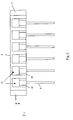
- FIG. 2 shows a schematic view of a Main Distribution Frame (MDF).
- MDF Main Distribution Frame
- This device may be located in a central office or remotely.
- Connector blocks 2 are locatable in a connection and protection plane 3 of the MDF which couple an input signal applied to the signal plane 4 via a connection and protection plane to the jumper plane 5.
- the signal plane 4 is the equipment side of the MDF, i.e. is connected to a legacy device such as a legacy switch.
- the present invention relates to a modified version of the connector block 2 which allows a variety of possibilities, e.g. the connection of a new service or equipment while maintaining legacy services or maintaining potential access to legacy services or also allowing disconnection of the legacy service once the new service is functional, or disconnection of the new service and return to the legacy service if this is necessary.
- FIG. 3 A schematic generic connector block in accordance with embodiments of the present invention is shown in Fig. 3 .
- the functional elements of the connector block are:
- the disconnection unit may include a disconnect device and a coupler. When inserted in the MDF, the coupler is connected directly to the conductor paths in the lVmF.
- the disconnect device can take various forms.
- the disconnect device can be physically separable from the connector block, e.g. can be provided by a jumper cable or a plug-in connector.
- the change of state can be also achieved by activatable, e.g. switchable devices such as switches or relays.
- the disconnect device is provided by the switches or relays. Where the disconnect/connect function is provided by switches or relays, these do not require physical removal from the connector block 2 to allow a change of state of the disconnect unit.
- the switches or relays may be remotely actvatable, e.g. electrically by means of remote electrical control signals or activatable only locally to the connector block 2, e.g. manually.
- the new equipment may be connected using a fan-out, e.g. with multi-pair connectors which connect to the connectors 7.
- a test access point 10 may be provided (additionally) for providing testing facilities for the connections in the MDF (not shown).
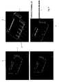
- FIGS 4A to C show various schematic connector blocks in accordance with embodiments of the present invention.
- Each connector block 2 has conductive elements 9 for connecting to the ground, connectors 16 (not shown) for connection to the connection and protection plane of an MDF to thereby connect an incoming signal from legacy equipment present on the signal plane to the jumper plane as well as optional protection units 17 (not shown) connected to the connectors 16, e.g. for providing overvoltage protection.
- Such elements 9 may be insertable in the conventional manner. For example, these elements plug into the distribution frame in a conventional manner.
- Each arrangement shown in Figure 4 has a connector 12, e.g. on a fan-out 11, which is connected by the connector 12 to a connector 7 which is included in the connector block 2 and which provides the connection to the new equipment.
- the connector 7 may include additional interconnection devices 13 to select a certain number of cable pairs from the total number of these available in the fan-out connector 12, e.g. to select 5 out of 25 pairs (see Fig. 4C ).
- the fan-out 11, for instance, can have 25 pair connectors 12 or 5 pair connectors 12.
- each connector block 2 has a disconnect unit 8 which may be an electrically or a mechanically operated disconnect unit.
- FIG. 4A in which a mechanically separable device is used for the disconnection unit 8 such as a jumper cable or a connector,
- the disconnect unit 8 includes a switch 8' such as a dip switch or a slide switch or a relay.
- the connector block 2 may be a remotely operable unit such as one comprising latched relays 8' in the disconnection unit.
- Figure 4C shows a device similar to the one of Figure 4A but with a unit 13 for selecting a certain number of pairs (e.g. 5) from a fan-out connector for more pairs (e.g. 25).
- Each connector block in Figure 4 may have an optional test access 10.
- FIG. 5A shows a fan-out 11 for connection to a new device such as an MSAN by means of a connector 14, the fan-out comprising cable and 5 pair connectors 12. Each connector 12 can be plugged into a connector 7 of a relevant block 2.
- Figure 5B a similar arrangement is shown for a fan-out with 25 pair connectors.
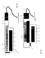
- FIGS 6A and 6B show exploded views of a connector block 2 in accordance with an embodiment of the present invention.
- This device has a new equipment connector 7, conductive elongate elements 9 for grounding, optional protection units 17 and connectors 16 for making the connections to the MDF and providing the signal paths to join the signal pane to the jumper plane and a housing 6.
- a housing e.g. on a top edge, one or more mechanical disconnect units 8, 8' are provided in the housing, e.g. on a top edge.
- Each of these units comprises a connector or coupler 8 and a disconnect device provided by switches. These disconnect devices may be in the form of slide switches.
- An optional test access can be provided.
- Figures 7A and 7B show exploded views of a connector block 2 in accordance with yet another embodiment with a housing 6, a new equipment connector 7, conductive elongate elements 9 for grounding, optional protection units 17 and connectors 16 for making the connections to the MDF and providing the signal paths to join the signal pane to the jumper plane as well as a mechanical disconnect unit 8 comprising a coupler and a disconnect device 8' such as dipswitches.
- An optional test access can be provided.
- Figure 8 shows a connector block 2 in accordance with a further embodiment.
- the disconnect device 8' is provided by a jumper cable 15.
- the disconnect/connect action is obtained by attaching the jumper cable with the fan out 11 with a connector 12 to a connector 7 and then attaching at least one of the ends 8' of the jumper cable to a connector 8 or detaching at least one of the ends 8' of the jumper cable 15.
- a housing 6, a new equipment connector 7, conductive elongate elements 9 for grounding, optional protection units 17 and connectors 16 for making the connections to the MDF and providing the signal paths to join the signal pane to the jumper plane are provided.
- a test access may be provided.
- Figure 9 shows a mechanical disconnect unit 8 located on a top edge of the connector block 2.
- the disconnect unit 8 is in the form of coupler 8 and a connector 8'.
- a housing 6, and a new equipment connector 7 are provided.
- Conductive elongate elements 9 for grounding are provided.
- Optional protection units 17 and connectors 16 for making the connections to the MDF and providing the signal paths to join the signal pane to the jumper plane can be provided but are not shown.
- An optional test access 10 can be provided as shown in Figure 10 .
- the test access unit 10 is provided on a side edge face of the connector block 2.
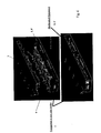
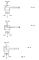
- Figure 11 shows schematically how any of the above mentioned connector blocks 2 in accordance with embodiments of the present invention are used.
- Figure 11a shows a connector block 2 in accordance with any of the embodiments of the present invention.
- a block housing or body 6 is provided made of an insulating material such as plastic.
- Elongate conductive elements, e.g. metal elements 9 are provided which plug into the connection and protection plane of the MDF and are used to connect to ground as well as connectors 16 (not shown) for connection to the signal plane 4 of the MDF to connections on the jumper plane 5 via the connection and protection plane so that a signal applied to the signal plane 4 is transferred to the jumper plane 5.
- Optional protection units 17 are also provided in electrical contact with the connectors 16 for providing protection, e.g.
- the signal is provided from a legacy device such as a legacy switch.
- Unit 7 is a connector for connecting new equipment to the MDF. It provides a signal path for a signal from the new equipment to the jumper plane 5 as well as either maintaining the signal path from the old legacy device.
- All of A) to C) allow connection to be made to the new device and a return to the legacy device if required.
- A in a first state of the connector block the legacy device and the new device are connected in parallel which allows the legacy device to be used or the new device to be used. In a second state only the new device can be used.
- B in a first state of the connector block only the new device is connected and can be used.
- a second state only the legacy device can be used, e.g. when returning after failure of the new device.
- C in a first state of the connector block only the new device is connected. In a second state the legacy device and the new device are connected in parallel, i.e. either the legacy or the new device can be used, e.g. when returning after failure of the new device. Of these A) is preferred.
- All of A), D) and E) allow connection to be made to the legacy device and a change to the new device as required.
- A in a first state of the connector block the legacy device and the new device are connected in parallel which allows the legacy device to be used. In a second state only the new device can be used.
- D in a first state of the connector block only the legacy device is connected.
- the legacy device and the new device are connected in parallel, i.e. the new device can be used.
- E in a first state of the connector block only the legacy device is connected and can be used. In a second state only the new device can be used.
- A) is still preferred but and E) is an acceptable alternative.
- the lines 100a and 100b are connected to the subscriber line going out from the remote device or from the central office/exchange.
- Lines 101a and 101b are connected to the first signal path, e.g. to a legacy switch.
- Lines 102a and 102b are connected to the second signal path, e.g. the new electronic device such as a switch providing xDSL service.
- Reference numeral 103 refers to a block including the disconnect unit.
- An optional protection unit, e.g. overvoltage protection is shown as item 104.
- a connection to ground, e.g. pin 9, is given the reference number 105.
- the first state of the connector block (which depends on the sate of the disconnect unit as indicated above) can be either only connected to the first signal path, e.g. providing a POTS service or both first and second signal paths are provided.
- the second state shown schematically in Fig. 13c only the second signal path, e.g; the new telecommunications service such as xDSL is provided.
- FIG 11B shows the disconnect element 8' inserted in the disconnect unit 8 and Figure 11C shows it removed.
- This disconnect/connect function is provided by switches or relays which do not require physical removal from the connector block 2.
- the new equipment may be connected using a fan-out with connectors which connect to the connectors 7 (not shown).
- a test access point may be provided for providing testing facilities for the connections in the MDF (not shown).
- a disconnect unit 8 allows the disconnection of the connections between the signal plane 4 and the jumper plane 5 which are provided by the conductive elements 9.
- the disconnect unit 8 allows connection or disconnection of the legacy equipment as well as the connection or disconnection of the new equipment. Dependent upon the design any of the system A) to C) mentioned above may be implemented.
- the disconnect unit 8 may be remotely operated, e.g. it comprises relays, or it may be a mechanical disconnect unit such as a manually operated switch or a manually removable connector.
- Figures 11D and E show to views of an MDF with a connector block attached according to embodiments of the present invention and having the disconnect element attached.
- the connection and protection plane, the signal plane and the jumper plane are indicated.
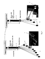
- FIGS 12a and b show schematic wiring diagrams for a connector block in accordance with an embodiment of the invention.
- a connector block for a distribution frame is shown schematically. This has five service connection locations 20 - 25 whereby only the first and the last are shown.
- Each location has an earthing pin 9 as shown for example in Figures 3 , 4 and 6 to 11 .
- each location also has a number of contacts 16, e.g. 16.1 to 16.4, each for making contact with, for example, pins sticking up from the distribution frame and pairwise connectable to customer premises and to an electronic device such as a legacy switch.
- Such contacts 16 are shown in Figures 3 , 6-8 flanking the grounding pin 9.
- Pins on the distribution frame are for making contact with a pair of cores of a telephone cable - one pair in the direction of the customer premises and one pair in the direction of the legacy switch.
- pins of the distribution frame are inserted in contacts 16.1 and 16.4, which are thereby connected to the customer premises and contacts 16.2 and 16.3 to the legacy switch (see Fig. 1 for the placement of these items).
- the connector block could also have pins and the frame female contacts or any other form of contacts.
- a protection circuit 17 may also be provided as shown, e.g. for overvoltage protection, connected for example to the customer lines.
- the connector block has connectors 7 for connecting to an additional service, e.g. an xDSL service.
- These connectors 7 are pairwise connected to a new electronic device, e.g. one pair, 7' and 7", to a switch on the network side and one pair 7"' and 7"" to the customer premises.
- Fuses F1 and F11 in service connection location 20 ?? up to F5 and F55 in service connection 25
- a connector 12 makes contact with the contacts 7 to provide the additional service, e.g. by insertion. Due to the internal wiring of the connector block, e.g.
- the individual lines connected to the contacts 7 are connected to the equivalent customer or network side contacts 16.1 to 16.4 as well as the protection unit 17 so that the signal paths to the legacy switch are in parallel to the signal paths to the new switch providing access to the xDSL service.
- FIG. 12B The way a disconnection unit can be implemented is shown schematically in Figure 12B .
- the contacts shown in this figure are for all five locations 20 to 25.
- the contacts are provided as couplers to the switch or customer side.
- 5x2 or 10 contacts are provided in total by the connector block for the customer side and 10 for the network side.
- the legacy switch is operational and because the contacts 7 are connected through in parallel, also the additional switch is connected in as well. Signals can be provided either by the legacy switch or by the new switch, e.g. for the xDS1 service. This allows graceful fall back in case the new service does not work correctly.
- disconnect device 8' If the disconnect device 8' is removed (or disconnected by other means, e.g. switches, relays, etc.) then the connection between the legacy switch and the network side is broken. This leaves only the new switch operational. The interruptions with the pairs are in the connector block itself - this means that the lengths of cable open circuited are reduced to a minimum, hence reducing the "stub effect" to a minimum. If the disconnection unit is reinserted then the legacy switch is made operational again.
- test access may be provided but this is not shown in Figure 12 .
Claims (22)
- Verteiler mit mindestens einem Anschlussblock, wobei der Anschlussblock mechanisch mit dem Verteiler verbunden ist, um dadurch elektrisch mit dem Verteiler zu kooperieren, um einen ersten Signalweg zwischen einer ersten Seite und einer zweiten Seite des Verteilers bereitzustellen, wobei die erste Seite des Verteilers mit einer Teilnehmerleitung verbunden ist und die zweite Seite des Verteilers und der erste Signalweg mit einer Vorläufer-Vermittlungseinrichtung verbunden sind, gekennzeichnet dadurch, dass der Anschlussblock über Anschlussmittel zum Anschließen eines Signalkabels für einen zusätzlichen Telekommunikationsdienst verfügt und mit einem Kommunikationsweg zum Bereitstellen eines zweiten Signalwegs zwischen dem Signalkabel und der ersten Seite des Verteilers versehen ist, wobei das Signalkabel mit einer neuen elektronischen Vorrichtung zum Bereitstellen des zusätzlichen Telekommunikationsdienstes verbunden ist, und
der Anschlussblock außerdem über eine Trenneinheit verfügt, um zwei Zustände des Anschlussblocks bereitzustellen, wobei in dem ersten Zustand mindestens der erste Signalweg bereitgestellt wird und in dem zweiten Zustand mindestens der zweite Signalweg bereitgestellt wird. - Verteiler nach Anspruch 1, wobei in dem ersten Zustand der zweite Signalweg nicht bereitgestellt wird.
- Verteiler nach einem der vorstehenden Ansprüche, wobei in dem zweiten Zustand der erste Signalweg nicht bereitgestellt wird.
- Verteiler nach einem der vorstehenden Ansprüche, wobei die Trenneinheit entfernt von dem ersten Zustand in den zweiten Zustand geschaltet werden kann.
- Verteiler nach einem der Ansprüche 1 bis 3, wobei die Trenneinheit eine Trennvorrichtung und einen Koppler umfasst, wobei der Koppler eine Verbindung zu dem Verteiler bereitstellt, wenn der Anschlussblock darin eingesetzt ist, wobei die Trennvorrichtung entfernt aktivierbar ist oder nur lokal für den Verteiler aktivierbar ist.
- Verteiler nach Anspruch 5, wobei die lokal aktivierbare Trennvorrichtung ein Schalter, ein Relais, ein Uberbrückungskabel oder ein Steckverbinder ist.
- Verteiler nach Anspruch 5, wobei die entfernt aktivierbare Trennvorrichtung ein Schalter oder ein Relais ist.
- Verteiler nach einem der vorstehenden Ansprüche, wobei der zusätzliche Telekommunikationsdienst nicht nur ein Prüfzugang ist.
- Verteiler nach einem der vorstehenden Ansprüche, wobei der Anschlussblock weiterhin einen Prüfzugangspunkt umfasst.
- Verteiler nach einem der vorstehenden Ansprüche, wobei der zweite Signalweg für einen DSL-Dienst ist.
- Verteiler nach einem der Ansprüche 1 bis 10, wobei die Trenneinheit angepasst ist, um den ersten und den zweiten Signalweg parallel in dem ersten Zustand bereitzustellen.
- Verteiler nach einem der vorstehenden Ansprüche, wobei der erste Signalweg für einen Telefondienst ist.
- Anschlussblock zur Verwendung mit einem Verteiler, wobei der Anschlussblock über Mittel zum Verbinden des Anschlussblocks mit dem Verteiler verfügt, um dadurch elektrisch mit dem Verteiler zu kooperieren, um einen ersten Signalweg zwischen einer ersten Seite und einer zweiten Seite des Verteilers bereitzustellen, gekennzeichnet dadurch, dass der Anschlussblock außerdem über Anschlussmittel zum Anschließen eines Signalkabels für einen zusätzlichen Telekommunikationsdienst verfügt und mit einem Kommunikationsweg zum Bereitstellen eines zweiten Signalwegs zwischen dem Signalkabel und der ersten Seite des Verteilers versehen ist und weiterhin eine Trenneinheit umfasst, um zwei Zustände des Anschlussblocks bereitzustellen, wobei in dem ersten Zustand mindestens der erste Signalweg bereitgestellt wird und in dem zweiten Zustand mindestens der zweite Signalweg bereitgestellt wird.
- Anschlussblock nach Anspruch 13, wobei in dem ersten Zustand der zweite Signalweg nicht bereitgestellt wird.
- Anschlussblock nach einem der Ansprüche 13 oder 14, wobei in dem zweiten Zustand der erste Signalweg nicht bereitgestellt wird.
- Anschlussblock nach einem der Ansprüche 13 bis 15, wobei die Trenneinheit entfernt von dem ersten Zustand in den zweiten Zustand geschaltet werden kann.
- Anschlussblock nach einem der Ansprüche 13 bis 15, wobei die Trenneinheit eine Trennvorrichtung und einen Koppler umfasst, wobei der Koppler eine Verbindung zu dem Verteiler bereitstellt, wenn der Anschlussblock damit verbunden ist, wobei die Trennvorrichtung entfernt aktivierbar ist oder nur lokal für den Anschlussblock aktivierbar ist.
- Anschlussblock nach Anspruch 17, wobei die lokal aktivierbare Trennvorrichtung ein Schalter, ein Relais, ein Uberbrückungskabel oder ein Steckverbinder ist.
- Anschlussblock nach Anspruch 17, wobei die entfernt aktivierbare Trennvorrichtung ein Schalter oder ein Relais ist.
- Anschlussblock nach einem der Ansprüche 13 bis 19, wobei die Trenneinheit angepasst ist, um den ersten und den zweiten Signalweg parallel in dem ersten Zustand bereitzustellen.
- Anschlussblock nach einem der Ansprüche 13 bis 20, wobei der Anschlussblock weiterhin einen Prüfzugangspunkt umfasst.
- Verfahren zum Verbinden eines zusätzlichen Dienstes mit einem Verteiler mit mindestens einem Anschlussblock, wobei der Anschlussblock mechanisch mit dem Verteiler verbunden ist, um dadurch elektrisch mit dem Verteiler zu kooperieren, um einen ersten Signalweg zwischen einer ersten Seite und einer zweiten Seite des Verteilers bereitzustellen, das Verfahren umfassend:Anschließen eines Signalkabels für den zusätzlichen Telekommunikationsdienst an den Anschlussblock, um dadurch einen zweiten Signalweg zwischen dem Signalkabel und der ersten Seite des Verteilers bereitzustellen, undUmschalten, durch den Anschlussblock, zwischen zwei Zuständen des Anschlussblocks, wobei in dem ersten Zustand mindestens der erste Signalweg bereitgestellt wird und in dem zweiten Zustand mindestens der zweite Signalweg bereitgestellt wird.
Applications Claiming Priority (4)
| Application Number | Priority Date | Filing Date | Title |
|---|---|---|---|
| GB0510047A GB0510047D0 (en) | 2005-05-17 | 2005-05-17 | Disconnection points in a telecommunication system |
| GB0511843A GB0511843D0 (en) | 2005-06-10 | 2005-06-10 | Disconnection points in a telecommunications system |
| GB0511958A GB0511958D0 (en) | 2005-06-13 | 2005-06-13 | Disconnection points in a telecommunications system |
| PCT/EP2006/004631 WO2006122758A1 (en) | 2005-05-17 | 2006-05-16 | Disconnection points in a telecommunication system |
Publications (2)
| Publication Number | Publication Date |
|---|---|
| EP1884122A1 EP1884122A1 (de) | 2008-02-06 |
| EP1884122B1 true EP1884122B1 (de) | 2009-03-25 |
Family
ID=36637538
Family Applications (1)
| Application Number | Title | Priority Date | Filing Date |
|---|---|---|---|
| EP06753656A Not-in-force EP1884122B1 (de) | 2005-05-17 | 2006-05-16 | Trennungspunkte in einem telekommunikationssystem |
Country Status (5)
| Country | Link |
|---|---|
| EP (1) | EP1884122B1 (de) |
| AT (1) | ATE427006T1 (de) |
| DE (1) | DE602006005921D1 (de) |
| GB (1) | GB2426387B (de) |
| WO (1) | WO2006122758A1 (de) |
Families Citing this family (3)
| Publication number | Priority date | Publication date | Assignee | Title |
|---|---|---|---|---|
| GB2444095A (en) * | 2006-11-21 | 2008-05-28 | Tyco Electronics Raychem Nv | Connector block with disconnection points used in a distribution frame |
| GB2457697B (en) * | 2008-02-21 | 2012-03-21 | Tyco Electronics Raychem Bvba | Switching and testing arrangement for telephone networks |
| GB2577060B (en) * | 2018-09-11 | 2022-01-12 | British Telecomm | Adaptor |
Family Cites Families (4)
| Publication number | Priority date | Publication date | Assignee | Title |
|---|---|---|---|---|
| US5802170A (en) * | 1994-05-19 | 1998-09-01 | Tii Industries, Inc. | Customer bridge module |
| EP0766482A3 (de) * | 1995-09-29 | 2000-02-02 | KRONE Aktiengesellschaft | Verteilereinrichtung für die Telekommunikations- und Datentechnik |
| GB0012484D0 (en) * | 2000-05-24 | 2000-07-12 | Channell Ltd | Telecommunications connector |
| ES2309390T3 (es) * | 2002-10-03 | 2008-12-16 | Tyco Electronics Raychem S.A. | Acceso metalico de prueba para conectores xdsl. |
-
2006
- 2006-05-16 WO PCT/EP2006/004631 patent/WO2006122758A1/en not_active Application Discontinuation
- 2006-05-16 DE DE602006005921T patent/DE602006005921D1/de active Active
- 2006-05-16 EP EP06753656A patent/EP1884122B1/de not_active Not-in-force
- 2006-05-16 AT AT06753656T patent/ATE427006T1/de not_active IP Right Cessation
- 2006-05-16 GB GB0609631A patent/GB2426387B/en not_active Expired - Fee Related
Also Published As
| Publication number | Publication date |
|---|---|
| EP1884122A1 (de) | 2008-02-06 |
| GB2426387B (en) | 2008-09-17 |
| ATE427006T1 (de) | 2009-04-15 |
| WO2006122758A1 (en) | 2006-11-23 |
| DE602006005921D1 (de) | 2009-05-07 |
| GB2426387A (en) | 2006-11-22 |
| GB0609631D0 (en) | 2006-06-21 |
Similar Documents
| Publication | Publication Date | Title |
|---|---|---|
| US6371780B1 (en) | RJ jack with switch | |
| US6322375B1 (en) | Network interface device with circuit board architecture | |
| IL103745A (en) | Electrical connector | |
| US6229890B1 (en) | Network interface device with automatic connector closure | |
| EP1884122B1 (de) | Trennungspunkte in einem telekommunikationssystem | |
| JP4184978B2 (ja) | 測定装置および電気通信アセンブリ | |
| WO2008062222A2 (en) | Disconnection points in a telecommunication system | |
| CN101151910B (zh) | 电信模块和包括至少一个电信模块的组件 | |
| CN1934877B (zh) | 电信领域中的模块配置 | |
| KR100780162B1 (ko) | Xdsl 접속용 금속 테스트 액세스 | |
| EP1931167B1 (de) | Schaltmodul in einer Verteilstelle im Telekommunikationsbereich und Baugruppen damit, sowie Verwendungsverfahren dafür | |
| GB2457697A (en) | Switching and testing arrangement for telephone networks, using power provided over phone line | |
| US6616460B1 (en) | Telecommunications connector | |
| WO2007132162A1 (en) | Improvements in xdsl service provision | |
| US6166895A (en) | Patch cable and method for installing telecommunications equipment in remote terminals | |
| EP1450450B1 (de) | Telekommunikationsverbinder | |
| WO2018134651A1 (en) | Professional and secure terminal splitter for adsl optimized wiring mdf | |
| EP1158612B1 (de) | Steckverbinder für die Telekommunikation | |
| US7499526B2 (en) | Termination module including subscriber bridge having burglar alarm connections | |
| GB2425223A (en) | Switching apparatus for connection to a five point overvoltage protection socket in an exchange | |
| CN101351927A (zh) | 包括至少一个通信模块,测试总线和部件套件的通信组件 | |
| MXPA06010517A (en) | Modular arrangement in the field of telecommunications | |
| MX2008008314A (en) | A telecommunications assembly including at least one telecommunications module, a test bus and a kit of parts |
Legal Events
| Date | Code | Title | Description |
|---|---|---|---|
| PUAI | Public reference made under article 153(3) epc to a published international application that has entered the european phase |
Free format text: ORIGINAL CODE: 0009012 |
|
| 17P | Request for examination filed |
Effective date: 20071205 |
|
| AK | Designated contracting states |
Kind code of ref document: A1 Designated state(s): AT BE BG CH CY CZ DE DK EE ES FI FR GB GR HU IE IS IT LI LT LU LV MC NL PL PT RO SE SI SK TR |
|
| 17Q | First examination report despatched |
Effective date: 20080411 |
|
| DAX | Request for extension of the european patent (deleted) | ||
| GRAP | Despatch of communication of intention to grant a patent |
Free format text: ORIGINAL CODE: EPIDOSNIGR1 |
|
| GRAS | Grant fee paid |
Free format text: ORIGINAL CODE: EPIDOSNIGR3 |
|
| GRAA | (expected) grant |
Free format text: ORIGINAL CODE: 0009210 |
|
| RBV | Designated contracting states (corrected) |
Designated state(s): AT BE BG CH CY CZ DE DK EE ES FI FR GR HU IE IS IT LI LT LU LV MC NL PL PT RO SE SI SK TR |
|
| AK | Designated contracting states |
Kind code of ref document: B1 Designated state(s): AT BE BG CH CY CZ DE DK EE ES FI FR GR HU IE IS IT LI LT LU LV MC NL PL PT RO SE SI SK TR |
|
| REG | Reference to a national code |
Ref country code: CH Ref legal event code: EP |
|
| REG | Reference to a national code |
Ref country code: IE Ref legal event code: FG4D |
|
| REF | Corresponds to: |
Ref document number: 602006005921 Country of ref document: DE Date of ref document: 20090507 Kind code of ref document: P |
|
| PG25 | Lapsed in a contracting state [announced via postgrant information from national office to epo] |
Ref country code: FI Free format text: LAPSE BECAUSE OF FAILURE TO SUBMIT A TRANSLATION OF THE DESCRIPTION OR TO PAY THE FEE WITHIN THE PRESCRIBED TIME-LIMIT Effective date: 20090325 Ref country code: LT Free format text: LAPSE BECAUSE OF FAILURE TO SUBMIT A TRANSLATION OF THE DESCRIPTION OR TO PAY THE FEE WITHIN THE PRESCRIBED TIME-LIMIT Effective date: 20090325 Ref country code: SI Free format text: LAPSE BECAUSE OF FAILURE TO SUBMIT A TRANSLATION OF THE DESCRIPTION OR TO PAY THE FEE WITHIN THE PRESCRIBED TIME-LIMIT Effective date: 20090325 |
|
| PG25 | Lapsed in a contracting state [announced via postgrant information from national office to epo] |
Ref country code: AT Free format text: LAPSE BECAUSE OF FAILURE TO SUBMIT A TRANSLATION OF THE DESCRIPTION OR TO PAY THE FEE WITHIN THE PRESCRIBED TIME-LIMIT Effective date: 20090325 Ref country code: LV Free format text: LAPSE BECAUSE OF FAILURE TO SUBMIT A TRANSLATION OF THE DESCRIPTION OR TO PAY THE FEE WITHIN THE PRESCRIBED TIME-LIMIT Effective date: 20090325 Ref country code: SE Free format text: LAPSE BECAUSE OF FAILURE TO SUBMIT A TRANSLATION OF THE DESCRIPTION OR TO PAY THE FEE WITHIN THE PRESCRIBED TIME-LIMIT Effective date: 20090625 Ref country code: PL Free format text: LAPSE BECAUSE OF FAILURE TO SUBMIT A TRANSLATION OF THE DESCRIPTION OR TO PAY THE FEE WITHIN THE PRESCRIBED TIME-LIMIT Effective date: 20090325 |
|
| NLV1 | Nl: lapsed or annulled due to failure to fulfill the requirements of art. 29p and 29m of the patents act | ||
| PG25 | Lapsed in a contracting state [announced via postgrant information from national office to epo] |
Ref country code: ES Free format text: LAPSE BECAUSE OF FAILURE TO SUBMIT A TRANSLATION OF THE DESCRIPTION OR TO PAY THE FEE WITHIN THE PRESCRIBED TIME-LIMIT Effective date: 20090706 Ref country code: EE Free format text: LAPSE BECAUSE OF FAILURE TO SUBMIT A TRANSLATION OF THE DESCRIPTION OR TO PAY THE FEE WITHIN THE PRESCRIBED TIME-LIMIT Effective date: 20090325 Ref country code: PT Free format text: LAPSE BECAUSE OF FAILURE TO SUBMIT A TRANSLATION OF THE DESCRIPTION OR TO PAY THE FEE WITHIN THE PRESCRIBED TIME-LIMIT Effective date: 20090831 Ref country code: CZ Free format text: LAPSE BECAUSE OF FAILURE TO SUBMIT A TRANSLATION OF THE DESCRIPTION OR TO PAY THE FEE WITHIN THE PRESCRIBED TIME-LIMIT Effective date: 20090325 |
|
| PG25 | Lapsed in a contracting state [announced via postgrant information from national office to epo] |
Ref country code: RO Free format text: LAPSE BECAUSE OF FAILURE TO SUBMIT A TRANSLATION OF THE DESCRIPTION OR TO PAY THE FEE WITHIN THE PRESCRIBED TIME-LIMIT Effective date: 20090325 Ref country code: IS Free format text: LAPSE BECAUSE OF FAILURE TO SUBMIT A TRANSLATION OF THE DESCRIPTION OR TO PAY THE FEE WITHIN THE PRESCRIBED TIME-LIMIT Effective date: 20090725 Ref country code: SK Free format text: LAPSE BECAUSE OF FAILURE TO SUBMIT A TRANSLATION OF THE DESCRIPTION OR TO PAY THE FEE WITHIN THE PRESCRIBED TIME-LIMIT Effective date: 20090325 Ref country code: NL Free format text: LAPSE BECAUSE OF FAILURE TO SUBMIT A TRANSLATION OF THE DESCRIPTION OR TO PAY THE FEE WITHIN THE PRESCRIBED TIME-LIMIT Effective date: 20090325 |
|
| PG25 | Lapsed in a contracting state [announced via postgrant information from national office to epo] |
Ref country code: MC Free format text: LAPSE BECAUSE OF NON-PAYMENT OF DUE FEES Effective date: 20090531 |
|
| PG25 | Lapsed in a contracting state [announced via postgrant information from national office to epo] |
Ref country code: BG Free format text: LAPSE BECAUSE OF FAILURE TO SUBMIT A TRANSLATION OF THE DESCRIPTION OR TO PAY THE FEE WITHIN THE PRESCRIBED TIME-LIMIT Effective date: 20090625 Ref country code: DK Free format text: LAPSE BECAUSE OF FAILURE TO SUBMIT A TRANSLATION OF THE DESCRIPTION OR TO PAY THE FEE WITHIN THE PRESCRIBED TIME-LIMIT Effective date: 20090325 |
|
| PLBE | No opposition filed within time limit |
Free format text: ORIGINAL CODE: 0009261 |
|
| STAA | Information on the status of an ep patent application or granted ep patent |
Free format text: STATUS: NO OPPOSITION FILED WITHIN TIME LIMIT |
|
| REG | Reference to a national code |
Ref country code: FR Ref legal event code: ST Effective date: 20100129 |
|
| 26N | No opposition filed |
Effective date: 20091229 |
|
| REG | Reference to a national code |
Ref country code: IE Ref legal event code: MM4A |
|
| PG25 | Lapsed in a contracting state [announced via postgrant information from national office to epo] |
Ref country code: IE Free format text: LAPSE BECAUSE OF NON-PAYMENT OF DUE FEES Effective date: 20090516 Ref country code: FR Free format text: LAPSE BECAUSE OF NON-PAYMENT OF DUE FEES Effective date: 20090602 |
|
| PG25 | Lapsed in a contracting state [announced via postgrant information from national office to epo] |
Ref country code: GR Free format text: LAPSE BECAUSE OF FAILURE TO SUBMIT A TRANSLATION OF THE DESCRIPTION OR TO PAY THE FEE WITHIN THE PRESCRIBED TIME-LIMIT Effective date: 20090626 |
|
| REG | Reference to a national code |
Ref country code: CH Ref legal event code: PL |
|
| PG25 | Lapsed in a contracting state [announced via postgrant information from national office to epo] |
Ref country code: CH Free format text: LAPSE BECAUSE OF NON-PAYMENT OF DUE FEES Effective date: 20100531 Ref country code: LI Free format text: LAPSE BECAUSE OF NON-PAYMENT OF DUE FEES Effective date: 20100531 |
|
| PG25 | Lapsed in a contracting state [announced via postgrant information from national office to epo] |
Ref country code: LU Free format text: LAPSE BECAUSE OF NON-PAYMENT OF DUE FEES Effective date: 20090516 |
|
| PG25 | Lapsed in a contracting state [announced via postgrant information from national office to epo] |
Ref country code: HU Free format text: LAPSE BECAUSE OF FAILURE TO SUBMIT A TRANSLATION OF THE DESCRIPTION OR TO PAY THE FEE WITHIN THE PRESCRIBED TIME-LIMIT Effective date: 20090926 |
|
| PG25 | Lapsed in a contracting state [announced via postgrant information from national office to epo] |
Ref country code: TR Free format text: LAPSE BECAUSE OF FAILURE TO SUBMIT A TRANSLATION OF THE DESCRIPTION OR TO PAY THE FEE WITHIN THE PRESCRIBED TIME-LIMIT Effective date: 20090325 |
|
| PGFP | Annual fee paid to national office [announced via postgrant information from national office to epo] |
Ref country code: BE Payment date: 20110530 Year of fee payment: 6 |
|
| PG25 | Lapsed in a contracting state [announced via postgrant information from national office to epo] |
Ref country code: CY Free format text: LAPSE BECAUSE OF FAILURE TO SUBMIT A TRANSLATION OF THE DESCRIPTION OR TO PAY THE FEE WITHIN THE PRESCRIBED TIME-LIMIT Effective date: 20090325 |
|
| PGFP | Annual fee paid to national office [announced via postgrant information from national office to epo] |
Ref country code: IT Payment date: 20110524 Year of fee payment: 6 Ref country code: DE Payment date: 20110527 Year of fee payment: 6 |
|
| BERE | Be: lapsed |
Owner name: TYCO ELECTRONICS RAYCHEM NV Effective date: 20120531 |
|
| PG25 | Lapsed in a contracting state [announced via postgrant information from national office to epo] |
Ref country code: IT Free format text: LAPSE BECAUSE OF NON-PAYMENT OF DUE FEES Effective date: 20120516 Ref country code: BE Free format text: LAPSE BECAUSE OF NON-PAYMENT OF DUE FEES Effective date: 20120531 |
|
| REG | Reference to a national code |
Ref country code: DE Ref legal event code: R119 Ref document number: 602006005921 Country of ref document: DE Effective date: 20121201 |
|
| PG25 | Lapsed in a contracting state [announced via postgrant information from national office to epo] |
Ref country code: DE Free format text: LAPSE BECAUSE OF NON-PAYMENT OF DUE FEES Effective date: 20121201 |