EP1884047B1 - Antidrehungssystem zur gegendrehung und koaxiale rotornabenwellenverkleidung - Google Patents
Antidrehungssystem zur gegendrehung und koaxiale rotornabenwellenverkleidung Download PDFInfo
- Publication number
- EP1884047B1 EP1884047B1 EP06771238.0A EP06771238A EP1884047B1 EP 1884047 B1 EP1884047 B1 EP 1884047B1 EP 06771238 A EP06771238 A EP 06771238A EP 1884047 B1 EP1884047 B1 EP 1884047B1
- Authority
- EP
- European Patent Office
- Prior art keywords
- rotation
- shaft
- axis
- fairing
- rotor
- Prior art date
- Legal status (The legal status is an assumption and is not a legal conclusion. Google has not performed a legal analysis and makes no representation as to the accuracy of the status listed.)
- Ceased
Links
Images




Classifications
-
- B—PERFORMING OPERATIONS; TRANSPORTING
- B64—AIRCRAFT; AVIATION; COSMONAUTICS
- B64C—AEROPLANES; HELICOPTERS
- B64C27/00—Rotorcraft; Rotors peculiar thereto
- B64C27/04—Helicopters
- B64C27/12—Rotor drives
-
- B—PERFORMING OPERATIONS; TRANSPORTING
- B64—AIRCRAFT; AVIATION; COSMONAUTICS
- B64C—AEROPLANES; HELICOPTERS
- B64C1/00—Fuselages; Constructional features common to fuselages, wings, stabilising surfaces or the like
-
- B—PERFORMING OPERATIONS; TRANSPORTING
- B64—AIRCRAFT; AVIATION; COSMONAUTICS
- B64C—AEROPLANES; HELICOPTERS
- B64C27/00—Rotorcraft; Rotors peculiar thereto
- B64C27/04—Helicopters
- B64C27/08—Helicopters with two or more rotors
- B64C27/10—Helicopters with two or more rotors arranged coaxially
-
- B—PERFORMING OPERATIONS; TRANSPORTING
- B64—AIRCRAFT; AVIATION; COSMONAUTICS
- B64C—AEROPLANES; HELICOPTERS
- B64C27/00—Rotorcraft; Rotors peculiar thereto
- B64C27/04—Helicopters
- B64C27/12—Rotor drives
- B64C27/14—Direct drive between power plant and rotor hub
-
- B—PERFORMING OPERATIONS; TRANSPORTING
- B64—AIRCRAFT; AVIATION; COSMONAUTICS
- B64C—AEROPLANES; HELICOPTERS
- B64C7/00—Structures or fairings not otherwise provided for
-
- B—PERFORMING OPERATIONS; TRANSPORTING
- B64—AIRCRAFT; AVIATION; COSMONAUTICS
- B64C—AEROPLANES; HELICOPTERS
- B64C27/00—Rotorcraft; Rotors peculiar thereto
- B64C27/04—Helicopters
-
- B—PERFORMING OPERATIONS; TRANSPORTING
- B64—AIRCRAFT; AVIATION; COSMONAUTICS
- B64C—AEROPLANES; HELICOPTERS
- B64C27/00—Rotorcraft; Rotors peculiar thereto
- B64C27/20—Rotorcraft characterised by having shrouded rotors, e.g. flying platforms
-
- G—PHYSICS
- G01—MEASURING; TESTING
- G01S—RADIO DIRECTION-FINDING; RADIO NAVIGATION; DETERMINING DISTANCE OR VELOCITY BY USE OF RADIO WAVES; LOCATING OR PRESENCE-DETECTING BY USE OF THE REFLECTION OR RERADIATION OF RADIO WAVES; ANALOGOUS ARRANGEMENTS USING OTHER WAVES
- G01S1/00—Beacons or beacon systems transmitting signals having a characteristic or characteristics capable of being detected by non-directional receivers and defining directions, positions, or position lines fixed relatively to the beacon transmitters; Receivers co-operating therewith
- G01S1/02—Beacons or beacon systems transmitting signals having a characteristic or characteristics capable of being detected by non-directional receivers and defining directions, positions, or position lines fixed relatively to the beacon transmitters; Receivers co-operating therewith using radio waves
- G01S1/08—Systems for determining direction or position line
Definitions
- the present invention is directed to a rotor hub fairing system for a rotary-wing aircraft having a counter-rotating, coaxial rotor system, and more particularly, to a de-rotation system which rotationally stabilizes a shaft fairing mounted between an upper hub fairing and a lower hub fairing.
- the aerodynamic drag associated with a rotor hub on a rotary wing aircraft is a significant portion of the overall aircraft drag, typically 25% to 30% for conventional single-rotor helicopters.
- the rotor system drag increases for a rotary wing aircraft having a counter-rotating, coaxial rotor system primarily due to the dual rotor hubs and the interconnecting shaft therebetween.
- the increased drag resulting from the counter-rotating, coaxial rotor system may result in a relatively significant power penalty.
- the aerodynamic drag of the dual counter-rotating, coaxial rotor system is generated by three main components - the upper rotor hub assembly, the lower rotor hub assembly, and the interconnecting main rotor shaft assembly.
- the drag contribution may be approximately 40% for each of the hubs, and 20% for the interconnecting main rotor shaft assembly.
- a rotor hub fairing arrangement is mounted to each of the upper rotor hub and the lower rotor hub such that overall drag on the rotorcraft is reduced.
- the interconnecting main rotor shaft between the upper rotor hub assembly and the lower rotor hub assembly is typically exposed.
- contoured shaft fairings have been developed to cover the exposed interconnecting main rotor shaft.
- the shaft fairing is mounted to the counter-rotating, coaxial rotor system within a completely rotational environment between the upper hub fairing and the lower hub fairing through a bearing arrangement such that the shaft fairing is aligned with the fuselage in forward flight but is free to align with the relative wind during low speed maneuvering.
- a rotor hub fairing system for a dual, counter-rotating, coaxial rotor system generally includes an upper hub fairing, a lower hub fairing and a shaft fairing located therebetween.
- the rotor hub fairing system is attached to the counter-rotating, coaxial rotor system through a bearing arrangement such that the shaft fairing may be rotationally positioned at an azimuthal position about a main rotor axis of rotation relative the airframe by a de-rotation system.
- the de-rotation system controls the position of the shaft fairing about the axis of rotation such that the shaft fairing is prevented from rotating freely in unison with either rotor shaft as may otherwise result.
- One de-rotation system includes a belt driven system which self-aligns whenever the aircraft reaches a forward flight speed at which the airflow force is greater than the friction force between the belts and pulleys of the de-rotation system. This permits the de-rotation system to be designed for lower loads and thereby provides a light weight system.
- Another de-rotation system includes an upper plate, a lower plate, a drive cone assembly and a stationary support ring assembly.
- the upper plate rotates with one rotor shaft while the lower plate rotates with the other rotor shaft.
- the drive cone assembly includes a multitude of shaft-mounted beveled cones which mate between the upper and lower plates.
- a shaft extends radially outward from each beveled cone and is mounted to a stationary support ring of the stationary support ring assembly.
- the stationary support ring assembly supports the shaft fairing and may be manufactured as a C-section split ring to facilitate disassembly for maintenance checks.
- DE 102 41 608 A1 discloses an aircraft with a counter-rotating rotor system having a torque-inverting gear in between the two rotor systems, under US 478 379 A an unmanned aircraft is shown with a dual rotor system.
- US 6 443 530 B1 shows a children vehicle with covers for the hub and WO 99/04987 A1 shows a displaying device with rotating elements and a cover for the hub.
- the de-rotation system may additionally be operated in response to a control system through which the azimuthal position of the shaft fairing can be actively varied throughout all flight profiles.
- the de-rotation system generally includes a variable torque generator system, a controller in communication with the variable torque generator system and a shaft fairing position sensor in communication with the controller.
- the de-rotation system may also communicate with a flight control system to selectively azimuthally position the shaft fairing relative the airframe throughout all flight profiles to, for example, increase the maneuverability of the aircraft.
- the present invention therefore provide a de-rotation system for a shaft fairing within the completely rotational environment between an upper rotor hub fairing and a lower rotor hub fairing of a counter-rotating, coaxial rotor hub fairing system.
- FIGS 1A and 1B illustrate an exemplary vertical takeoff and landing (VTOL) rotary-wing aircraft 10 having a dual, counter-rotating, coaxial rotor system 12 which rotates about an axis of rotation A.
- the aircraft 10 includes an airframe 14 which supports the dual, counter rotating, coaxial rotor system 12 as well as an optional translational thrust system 30 which provides translational thrust generally parallel to an aircraft longitudinal axis L.
- VTOL vertical takeoff and landing
- the dual, counter-rotating, coaxial rotor system 12 includes an upper rotor system 16 and a lower rotor system 18.
- Each rotor system 16, 18 includes a plurality of rotor blades 20 mounted to a rotor hub 22, 24 for rotation about a rotor axis of rotation A.
- a plurality of the main rotor blades 20 project substantially radially outward from the hub assemblies 22, 24 and are connected thereto in any manner known to one of ordinary skill in the art (schematically illustrated at 21). Any number of blades 20 may be used with the rotor system 12.
- a main gearbox 26 which may be located above the aircraft cabin 28 drives the rotor system 12.
- the translational thrust system 30 may be driven by the same main gearbox 26 which drives the rotor system 12.
- the main gearbox 26 is driven by one or more engines (illustrated schematically at E). As shown, the gearbox 26 may be interposed between the gas turbine engines E, the rotor system 12 and the translational thrust system 30.
- the translational thrust system 30 may be mounted to the rear of the airframe 14 with a rotational axis T oriented substantially horizontal and parallel to the aircraft longitudinal axis L to provide thrust for high-speed flight.
- the translational thrust system 30 includes a pusher propeller 32 mounted within an aerodynamic cowling 34.
- the rotor system 12 includes a rotor hub fairing system 36, preferably an integrated rotor hub fairing system, generally located between and around the upper and lower rotor systems 16, 18 such that the rotor hubs 22, 24 are at least partially contained therein.
- the rotor hub fairing system 36 achieves a significant drag reduction in which large-scale flow separation is greatly reduced.
- the rotor hub fairing system 36 generally includes an upper hub fairing 38, a lower hub fairing 40 and a shaft fairing 42 therebetween.
- the rotor hub fairing system 36 is integrated to reduce interference effects between the separate fairings 38, 40, 42 and eliminate excessive separation in the junction areas.
- the term "integrated" as utilized herein means that the shaft fairing 42 generally follows the contours of the upper hub fairing 38 and the lower hub fairing 40 at the rotational interfaces therebetween.
- the lower hub fairing 40 is preferably integrated with the airframe 14 in an area typically referred to on a rotorcraft as a pylon 14D. It should be understood that fairing systems of various configurations will be usable with the present invention.
- the shaft fairing 42 is preferably attached to the counter-rotating, coaxial rotor system 12 through a bearing arrangement 43U, 43L (illustrated schematically) such that the shaft fairing 42 may be positioned at a relative angular position about the axis of rotation A relative the airframe 14 by a de-rotation system 44.
- the upper bearing 43U and the lower bearing 43L may be respectively located adjacent an upper portion and a lower portion of the shaft fairing 42.
- the upper bearing 43U is preferably attached to one rotor shaft 12U while the lower bearing 43L attached to the other rotor shaft 12L such that the bearings are counter rotating and the net bearing drag is relatively low.
- the de-rotation system 44 controls the position of the shaft fairing 42 about the axis of rotation A such that the shaft fairing 42 is prevented from rotating freely in unison with either shaft 12U, 12L as may otherwise result during some flight regimes.
- the de-rotation system 44A includes a gear train 46 to at least partially nullify rotation of the shaft fairing 42 which may otherwise occur due to parasitic friction of the bearing arrangement 43U, 43L.
- An upper belt 48U and a lower belt 48L engage the gear train 46 which are driven in equal but opposite directions about the axis of rotation.
- the upper belt 48U rotates with the rotor shaft 12U as the upper belt 48U is in engagement with an upper belt drive member 50U fixed for rotation with rotor shaft 12U.
- the lower belt 48L rotates with the rotor shaft 12L as the lower belt 48L is in engagement with a lower belt drive member 50L fixed for rotation with rotor shaft 12L.
- the upper belt 48U and the lower belt 48L are V-shaped belts or toothed belts, however, other members may alternatively be utilized.
- the tern "belt" is utilized herein, other members may likewise be utilized.
- the gear train 46 is mounted within a housing 52 located within the shaft fairing 42.
- the housing 50 is preferably attached to the inside of the shaft fairing 42 such that the essentially stationary housing 50 maintains the shaft fairing 42 essentially stationary with respect to the airframe 14.
- the housing 52 is preferably attached to the counter-rotating, coaxial rotor system 12 through the bearing arrangement 43U, 43L ( Figure 2C ) such that the housing 50 rotates with the shaft fairing 42 about the axis of rotation A.
- the upper bearing 43U and the lower bearing 43L are respectively located adjacent an upper portion and a lower portion of the housing 52.
- the upper bearing 43U is attached to one rotor shaft 12U while the lower housing bearing 43L is attached to the other rotor shaft 12L such that the bearings counter rotate and the net bearing drag is relatively low.
- the gear train 46 preferably includes an upper and lower shaft-mounted pulley 56U, 56L which rotate about an axis of rotation H.
- the upper and lower shaft-mounted pulley 56U, 56L are mounted within a housing support 58.
- the upper and lower shaft-mounted pulley 56U, 56L mount a respective bevel gear 60U, 60L.
- the bevel gears 60U, 60L are in meshing engagement with a common idler gear 62.
- the common idler gear 62 rotates about an axis of rotation C which is transverse to the axis of rotation H.
- the common idler gear 62 rotates about axis C but maintains an azimuthal position relative to the axis of rotation A such that the shaft fairing 42 maintains an azimuthal position relative to the aircraft 10.
- the de-rotation system 44A is belt driven, the de-rotation system 44A is self-correcting whenever the aircraft reaches a forward flight speed at which the force applied by airflow is greater than the friction force between the belts 48U and pulleys 56U, 56L. That is, should the shaft fairing 42 become misaligned, the forward flight speed at which the force applied by airflow is greater than the friction force between the belts 48U and pulleys 56U, 56L will realign the shaft fairing 42 with the longitudinal axis of aircraft 10. This permits the de-rotation system 44 to be designed for lower loads and thereby provides a light weight system.
- the frictional force may be set relatively low such that even low speed maneuvering such as side-slip maneuvers above a predefined velocity will also align the shaft faring 42 to a relative wind direction.
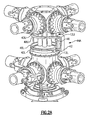
- another de-rotation system 44B at least partially nullifies rotation of the shaft fairing 42 which may otherwise occur due to parasitic friction of the bearing arrangement 43U, 43L.
- the de-rotation system 44B generally includes an upper plate 64U, a lower plate 64L, a drive cone assembly 66 and a stationary support ring assembly 68.
- the upper plate 64U rotates with the rotor shaft 12U as the upper plate 64U is fixed for rotation with rotor shaft 12U.
- the lower plate 64L rotates with the rotor shaft 12L as the lower plate 64L is fixed for rotation with rotor shaft 12L.
- the upper plate 64U and the lower plate 64L are concentric with the axis of rotation A and each include a respective beveled surface 70U, 70L which faces the opposite beveled surface 70L,70U (also illustrated in Figure 3B ).
- the drive cone assembly 66 includes a multitude of shaft-mounted beveled cones 72 ( Figures 3C and 3D ). That is, each shaft-mounted beveled cone 72 includes a frustro-conical member 74 which mates with and fits between the beveled surfaces 70U, 70L.
- the beveled cones 72 are preferably constructed with an exterior elastomeric surface having a high coefficient of friction while the beveled surface 70U, 70L includes a roughened contacting surface conducive to a high coefficient of friction.
- a friction drive with an elastomer is applied to the beveled cones 72 and the beveled surface 70U, 70L provides the roughened mating surface
- the elastomer coating may alternatively be applied to the beveled surface 70U, 70L and the beveled cones 72 could be prepared with the roughened surface.
- various friction drive materials and interfaces therebetween may alternatively or additionally be utilized with the present invention.
- a gear mesh such as a bevel gear or a face gear mesh may alternatively be substituted for the friction drive for applications requiring higher load capacities.
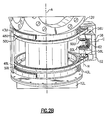
- a shaft 76 extends radially outward from each beveled cone 72 and is mounted to a stationary support ring 78 of the stationary support ring assembly 68 for rotation about an axis of rotation D.
- the stationary support ring assembly 78 is preferably manufactured as a C-section split ring ( Figure 3C ) to facilitate disassembly for maintenance checks.
- the stationary support ring assembly 78 preferably includes a drive cone bearing 77 ( Figure 3C ) to support each shaft 76 to facilitate rotation and alignment of each shaft-mounted beveled cone 72 about the respective axis of rotation D.
- a cone biasing member 79 ( Figure 3D ) such as a coil spring are preferably located between the rotating race of the drive cone bearing 77 and the outboard vertical flat of the beveled cone 72 to preload the beveled cone 72 toward the drive plate 64U, 64L.
- the drive cone assembly 66 and drive plates 64U, 64L are sized and configured so that rotation of rotor shaft 12L causes the drive cone assembly 66 to rotate about their respective axis D ( Figure 3C ), however since the rotor shaft 12U is rotating at substantially the same speed as rotor shaft 12L but in an opposite direction, the azimuthal location of each shaft-mounted bevel cone 72 remains substantially stationary with respect to the airframe 10. That is, since each shaft-mounted beveled cone 72 is free to rotate in place about each drive cone axis D but essentially prevented from azimuthal movement the rotor shaft axis of rotation A, the support ring assembly 68 which is affixed thereto, is essentially rotationally stationary with respect to the airframe 10 ( Figure 3A ).
- the shaft fairing 42 is mounted to the stationary support ring assembly 68 such that the shaft fairing 42 remains essentially stationary with respect to the airframe 10. That is, the shaft fairing 42 is prevented from rotating in unison with the rotor shaft by affixing the shaft fairing 42 to the stationary support ring assembly 68.
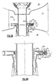
- the shaft fairing is preferably mounted to the stationary support ring assembly 68 by a bias assembly 80 ( Figure 3E ).
- the bias assembly 80 is preferably an alignment member 82 fixed to the shaft fairing 42 and located within an annular groove 84 of the stationary support ring 78 such that the shaft fairing 42 may rotate about the stationary support ring 78 as limited by centering springs 86 located between the stationary support ring 78 and the and the shaft fairing 42.
- the alignment member 82 may take various forms which essentially define an outer race relative the stationary support ring 78.
- the bias assembly 80 permits the shaft fairing 42 to at least partially align with relative airflow in sideward flight, lowering the loads on the de-rotation system 44B while maintaining the shaft fairing 42 in a centered position during hover.
- another de-rotation system 44C at least partially nullifies rotation of the shaft fairing 42 which may otherwise occur due to parasitic friction of the bearing arrangement 43U, 43L.
- the de-rotation system 44C in addition to de-rotation of the shaft fairing as described above, may additionally be operated in response to a control system through which the azimuthal position of the shaft fairing 42 may be actively varied throughout all flight profiles.
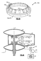
- the de-rotation system 44C generally includes a variable torque generator system 90, a controller 92 in communication with the variable torque generator system 90 and a shaft fairing position sensor 94 in communication with the controller 92.
- the de-rotation system 44C preferably communicates with a flight control system 96 to selectively azimuthally position the shaft fairing 42 relative the airframe 14 throughout all flight profiles.
- variable torque generator system 90 preferably includes an upper electromagnetic torque generator 98U mounted with respect to the rotor shaft 12U and a lower electromagnetic torque generator 98L mounted with respect to the rotor shaft 12L.
- Each electromagnetic torque generator 98U, 98L can be build with a predetermined amount of coning, so as to accommodated shaft fairing geometries that exhibit a "necking", or "hour-glass" shape ( Figure 4C ).
- Each electromagnetic torque generator 98U, 98L is mounted to the respective bearing arrangement 43U, 43L.
- the bearing arrangement 43U, 43L are preferred supports because of the inherent strength and precise machining typical of bearing construction.
- Each electromagnetic torque generator 98U, 98L includes an inner support structure 100 which rotates with the respective rotor shaft 12U, 12L and an outer support structure 102 mounted to the shaft fairing 42 such that the inner support structure 100 rotates relative the outer support structure 102.
- Each inner support structure 100 supports a multitude of permanent magnets 104 which form an azimuthally distributed pattern ( Figure 4D ).
- the outer support structure 102 supports an electromagnetic stator structure 106 which includes one or more coils that receive magnetic-flux excitation stimulation from the relative rotation between the permanent magnets 104 and the electromagnetic stator structure 106.
- the magnetic shear developed between the permanent magnets 104 and the electromagnetic stator structure 106 operates to selectively provide a torque on the shaft fairing 42.
- the magnetic shear is proportional to the electrical current flowing through the electromagnetic stator structure 106, hence the shear can be rapidly and accurately controlled by control of a current therethrough.
- each electromagnetic torque generator 98U, 98L is in electrical communication with a respective upper and lower current control 108U, 108L that communicates with the controller 92.
- the controller 92 incorporates the logic for control of the shaft fairing 42.
- the control system 92 preferably communicates with the flight control system 96 (illustrated schematically) to command the upper current control 108U and the lower current control 108L.
- the control system 92 is in electrical communication with an azimuthal position sensor 114 located within the shaft fairing 42.
- the azimuthal position sensor 114 preferably communicates wirelessly with a reference transmitter 116 located within the airframe 14.
- the sensor 114 and transmitter 116 preferably provides a signal proportional to the separation therebetween.
- the signal may preferably be essentially monotonic with angular displacement of the shaft fairing 42 so that displacements from a predetermined reference position in a first direction is positive while displacements in the opposite direction negative.
- the signal transmitted from transmitter 116 may be, for example only, a highfrequency electromagnetic wave field, spatially varying in amplitude (and preferentially in amplitude and frequency) to provide the spatial changes required for the sensor 114 to produce the monotonic signal.
- electromagnetic wave field may include a variety of fields includes a light field, hence an optical sensor (including an optical sensor observing a pre-selected pattern painted directly on the fuselage) will be usable with the present invention.
- an optical sensor including an optical sensor observing a pre-selected pattern painted directly on the fuselage
- the part of the current generated by the electromagnetic torque generator 98U, 98L may be utilized to power the control system 108.
- control system 92 may selectively dissipate the electric power produced by one of the electromagnetic torque generators 98U, 98L through a respective resistive element R1, R2 such that a differential magnetic shear force is generated between the electromagnetic torque generators 98U, 98L. That is, the resistive element R1, R2 selectively absorbs a portion of the magnetic shear force produced by the respective electromagnetic torque generators 98U, 98L
- the differential magnetic shear force causes the shaft fairing 42 to rotate with whichever electromagnetic torque generator 98U, 98L that is providing the relatively greater force. That is, the difference in torque generated by the upper and lower electromagnetic torque generators 98U, 98L results in a net torque that acts to rotate the shaft fairing 42 about the axis of rotation A.
- the control system 92 incorporates logic for shaft fairing 42 control and supplies the control signal to the upper current control 108U and a lower current control 108L in response to the signal generated by the sensor 114.
- another de-rotation system 44D includes a single electromagnetic torque generator 120 with a common central stator 122 between an upper electromagnetic rotor disk 124U and a lower electromagnetic rotor disk 124L.
- the electric current through an upper layer 126U and a lower layer 126L of the common central stator 122 are in opposite directions so that the generated electromagnetic torques acting on the upper electromagnetic rotor disk 124U and the lower electromagnetic rotor disk 124L are also in opposite directions.
- a single current controller is required, a relatively less complicated system is achieved.
Landscapes
- Engineering & Computer Science (AREA)
- Aviation & Aerospace Engineering (AREA)
- Mechanical Engineering (AREA)
- Retarders (AREA)
- Connection Of Motors, Electrical Generators, Mechanical Devices, And The Like (AREA)
- Tires In General (AREA)
- Toys (AREA)
- Turbine Rotor Nozzle Sealing (AREA)
Claims (22)
- Rotornaben-Verkleidungssystem für ein gegenläufig rotierendes Koaxialrotorsystem (10), aufweisend:eine obere Nabenverkleidung (38), die um eine Rotationsachse (A) gebildet ist und an der oberen Rotornabe (22) des Koaxialrotorsystems angebracht ist; undeine um die Achse gebildete untere Nabenverkleidung (40), die an der unteren Rotornabe (24) des Koaxialrotorsystems angebracht ist,dadurch gekennzeichnet, dass das System ferner aufweist:eine um die Rotationsachse (A) drehbar angebrachte Wellenverkleidung (42); undein an der Wellenverkleidung (42) angebrachtes Antirotationssystem (44A, 44B, 44C, 44D) zum Steuern der Rotation der Wellenverkleidung (42) um die Rotationsachse (A), wobei die Wellenverkleidung (42) zum Ausführen einer relativen Bewegung zwischen der oberen Nabenverkleidung (38) und der unteren Nabenverkleidung (40) angebracht ist, so dass die Wellenverkleidung in Bezug auf die Flugzeugzelle (14) des Flugzeugs (10) im Wesentlichen stationär bleibt.
- System nach Anspruch 1,
wobei das Antirotationssystem (44A) aufweist:ein Gehäuse, das an der Wellenverkleidung (42) angebracht ist;einen Getriebezug, der von dem Gehäuse (52) abgestützt ist;einen oberen Riemen (48U), der mit der Rotorwelle (12U) des oberen Rotorsystems (16) umläuft und mit einem oberen Antriebselement (50U) des Getriebezugs (46) zusammenwirkt, das sich um die Rotationsachse (A) dreht;einen unteren Riemen (48U), der mit der Rotorwelle (12L) des unteren Rotorsystems (18) umläuft und mit einem unteren Antriebselement (50L) des Getriebezugs (46) zusammenwirkt, das sich in einer einer entgegengesetzten Richtung zu dem oberen Antriebselement (50U) um die Rotationsachse (A) dreht. - System nach Anspruch 2,
wobei der Getriebezug ferner aufweist:eine obere Riemenscheibe (56U), die mit dem oberen Riemen (48U) zusammenwirkt;ein oberes Zahnrad (60U), das zur Drehung mit der oberen Riemenscheibe (56U) angebracht ist;eine untere Riemenscheibe (56L), die mit dem unteren Riemen (48L) zusammenwirkt;ein unteres Zahnrad (60L), das zur Drehung mit der unteren Riemenscheibe (56L) angebracht ist; undein Zwischenzahnrad (62), das mit dem oberen Zahnrad (60U) und dem unteren Zahnrad (60L) kämmend angeordnet ist - System nach Anspruch 3,
wobei die obere Riemenscheibe (56U) und die untere Riemenscheibe (56L) um eine erste Getriebezug-Rotationsachsse drehbar saind, die allgemein parallel zu der Rotationsachse (A) ist, wobei das Zwischenrad (62) um eine zweite Getriebezug-Rotationsachse definiert ist, die allgemein quer zu der ersten Getriebezug-Rotationsachse ist. - System nach Anspruch 3,
wobei der obere Riemen (48U) mit der oberen Riemenscheibe (56U) und dem oberen Antriebselement (50U) zusammenwirkt und der untere Riemen (48L) mit der unteren Riemenscheibe (56L) und dem unteren Antriebselement (50L) zusammenwirkt, und zwar durch eine Reibungskraft, die für eine Selbstausrichtung der Wellenverkleidung (42) oberhalb einer vorgegebenen Fluggeschwindigkeit sorgt. - System nach Anspruch 1,
wobei das Antirotationssystem aufweist:eine obere Platte (64U), die sich um die Rotationsachse (A) dreht;eine untere Platte (64L), die sich in einer entgegengesetzten Richtung zu dem oberen Antriebselement (50U) um die Rotationsachse dreht;eine Antriebskegelanordnung (66), die mit der oberen Platte (64U) und der unteren Platte (64L) zusammenwirkt; undeine stationäre Stützringanordnung (68), die an der Antriebskegelanordnung (66) angebracht ist, wobei die Wellenverkleidung an der stationären Stützringanordnung (68) angebracht ist. - System nach Anspruch 6,
wobei die obere Antriebsplatte (46U) eine abgeschrägte Fläche aufweist und die untere Antriebsplatte (46L) eine abgeschrägte Fläche aufweist, die der abgeschrägten Fläche der oberen Antriebsplatte zugewandt gegenüberliegt. - System nach Anspruch 7,
wobei die abgeschrägten Flächen jeweils eine aufgeraute Oberfläche aufweisen. - System nach Anspruch 7,
wobei die obere Antriebskegelanordnung (66) eine Vielzahl von abgeschrägten Steckkegeln (72) aufweist, die jeweils zwischen den abgeschrägten Flächen gehalten sind. - System nach Anspruch 9,
wobei jeder der abgeschrägten Kegel (72) eine elastomere Oberfläche aufweist. - System nach Anspruch 9,
wobei eine Welle von jedem der abgeschrägten Steckkegel (72) innerhalb der stationären Stützringanordnung (68) entlang einer Achse aufgenommen ist, die im Wesentlichen quer zu der Rotationsachse (A) ist. - System nach Anspruch 9,
wobei eine Welle (76) von jedem der abgeschrägten Steckkegel (72) in einem Lager (77) aufgenommen ist, das an der stationären Stützringanordnung (68) angebracht ist. - System nach Anspruch 1,
wobei das Antirotationssystem aufweist:ein variables Drehmomentgeneratorsystem (90) mit einer inneren Stützstruktur (100), die sich um die Rotationsachse (A) dreht, undmit einer äußeren Stützstruktur (102), die an der Wellenverkleidung (42) angebracht ist;ein Sensorsystem (114), das eine Position der Wellenverkleidung (42) erfasst; undeine Steuerung (92) in Kommunikation mit dem variablen Drehmomentgeneratorsystem (90) und dem Sensorsystem (114), wobei die Steuerung (92) betriebsmäßig zum Steuern der variablen Drehmomentgeneratorsystems (90) in Reaktion auf das Sensorsystem (114) ausgebildet ist, um die Wellenverkleidung (42) um die Rotationsachse zu positionieren. - System nach Anspruch 13,
wobei das variable Drehmomentgeneratorsystem (90) aufweist:einen elektromagnetischen Drehmomentgenerator, der sich um die Rotationsachse dreht. - System nach Anspruch 13,
wobei das variable Drehmomentgeneratorsystem (90) aufweist:einen oberen elektromagnetischen Drehmomentgenerator (98U), der sich um die Rotationsachse (A) dreht;einen unteren elektromagnetischen Drehmomentgenerator (98L), der sich in einer entgegengesetzten Richtung zu dem oberen elektromagnetischen Drehmomentgenerator (98U) um die Rotationsachse dreht. - System nach Anspruch 13,
wobei das variable Drehmomentgeneratorsystem an einem Lager angebracht ist. - System nach Anspruch 1,
wobei das Antirotationssystem (44A, 44B) ein passives Antirotationssystem ist, das an der Wellenverkleidung (42) angebracht ist, um unkontrollierte Rotation der Wellenverkleidung (42) um die Rotationsachse zu minimieren. - System nach Anspruch 1,
wobei das Antirotationssystem (44A, 44B) aufweist:ein Gehäuse (52), das an der Wellenverkleidung (42) angebracht ist;einen oberen Riemen (48U), der mit einem oberen Antriebselement (50U) des Getriebezugs (46) zusammenwirkt, wobei sich das obere Antriebselement (50) um die Rotationsachse dreht;einen unteren Riemen (48U), der mit einem unteren Antriebselement (50L) des Getriebezugs (46) zusammenwirkt, wobei sich das untere Antriebselement (50L) in einer entgegengesetzten Richtung zu dem oberen Antriebselement (50U) um die Rotationsachse (A) dreht;eine obere Riemenscheibe (56U), die zur Rotation relativ zu dem Gehäuse (52) angebracht ist, wobei die obere Riemenscheibe (56U) mit dem oberen Riemen (48U) zusammenwirkt; ;ein oberes Zahnrad (60U), das zur Rotation mit der oberen Riemenscheibe (56U) angebracht ist;eine untere Riemenscheibe (56L), die zur Rotation relativ zu dem Gehäuse (52) angebracht ist, wobei die untere Riemenscheibe mit dem unteren Riemen (48L) zusammenwirkt;ein unteres Zahnrad, das zur Rotation mit der unteren Riemenscheibe (56L) angebracht ist; undein Zwischenzahnrad (62), das zur Rotation relativ zu dem Gehäuse (52) angebracht ist, wobei das Zwischenzahnrad mit dem oberen Zahnrad und dem unteren Zahnrad kämmend angeordnet ist. - System nach Anspruch 17,
wobei das Antirotationssystem aufweist:eine obere Platte (64U), die sich mit der Rotorwelle (12U) um die Rotationsachse dreht;eine untere Platte (64L), die sich mit der Rotorwelle (12) in einer entgegengesetzten Richtung zu dem oberen Antriebselement (50U) um die Rotationsachse (A) dreht;eine Antriebskegelanordnung (66), die mit der oberen Platte (64U) und der unteren Platte (64L) zusammenwirkt;eine stationäre Stützringanordnung (68), die an der Antriebskegelanordnung (66) angebracht ist, wobei die Wellenverkleidung an der stationären Stützringanordnung (68) angebracht ist. - System nach Anspruch 1,
wobei das Antirotationssystem (44C, 44D) ein aktives Antirotationssystem ist, das an der Wellenverkleidung anbracht ist, um eine azimuthbezogene Positionierung der Wellenverkleidung um die Rotationsachse vorzunehmen. - System nach Anspruch 20,
wobei das Antirotationssystem (44C, 44D) aufweist:ein variables Drehmomentgeneratorsystem (90) mit einer inneren Tragstruktur (100), die an einem inneren Laufring eines Lagers (43) angebracht ist, das das Rotorsystem abstützt, wobei die innere Tragstruktur (100) betriebsmäßig dazu ausgebildet ist, sich mit dem Rotorsystem (44C, 44D) um die Hauptrotor-Rotationsachse (A) zu drehen, sowie mit einer äußeren Tragstruktur (102), die an einem äußeren Laufring des Lagers (43) und der Wellenverkleidung (42) angebracht ist;ein Sensorsystem (114), das eine Position der Wellenverkleidung erfasst; undeine Steuerung in Kommunikation mit dem variablen Drehmomentgeneratorsystem und dem Sensorsystem (114), wobei die Steuerung (92) betriebsmäßig zum Steuern des variablen Drehmomentgeneratorsystems in Reaktion auf das Sensorsystem (114) ausgebildet ist, um die Wellenverkleidung um die Hauptrotor-Rotationsachse (A) zu positionieren. - System nach Anspruch 21,
wobei die Steuerung (92) mit einem Flugsteuerungssystem (96) in Kommunikation steht.
Applications Claiming Priority (4)
| Application Number | Priority Date | Filing Date | Title |
|---|---|---|---|
| US68469405P | 2005-05-26 | 2005-05-26 | |
| US69359205P | 2005-06-24 | 2005-06-24 | |
| US77627806P | 2006-02-23 | 2006-02-23 | |
| PCT/US2006/020349 WO2006127955A2 (en) | 2005-05-26 | 2006-05-23 | De-rotation system for counter-rotating, coaxial rotor hub shaft fairing |
Publications (3)
| Publication Number | Publication Date |
|---|---|
| EP1884047A2 EP1884047A2 (de) | 2008-02-06 |
| EP1884047A4 EP1884047A4 (de) | 2013-04-24 |
| EP1884047B1 true EP1884047B1 (de) | 2014-07-30 |
Family
ID=37452857
Family Applications (1)
| Application Number | Title | Priority Date | Filing Date |
|---|---|---|---|
| EP06771238.0A Ceased EP1884047B1 (de) | 2005-05-26 | 2006-05-23 | Antidrehungssystem zur gegendrehung und koaxiale rotornabenwellenverkleidung |
Country Status (7)
| Country | Link |
|---|---|
| US (1) | US7621480B2 (de) |
| EP (1) | EP1884047B1 (de) |
| JP (1) | JP4688928B2 (de) |
| CN (1) | CN101636317B (de) |
| CA (1) | CA2610368C (de) |
| IL (1) | IL187636A0 (de) |
| WO (1) | WO2006127955A2 (de) |
Cited By (1)
| Publication number | Priority date | Publication date | Assignee | Title |
|---|---|---|---|---|
| RU2655249C1 (ru) * | 2017-07-06 | 2018-05-24 | Дмитрий Сергеевич Дуров | Скоростной вертолет-самолет-амфибия |
Families Citing this family (39)
| Publication number | Priority date | Publication date | Assignee | Title |
|---|---|---|---|---|
| US9434471B2 (en) | 2005-04-14 | 2016-09-06 | Paul E Arlton | Rotary wing vehicle |
| US12240633B2 (en) * | 2004-04-14 | 2025-03-04 | Paul E. Arlton | Rotary wing vehicle |
| EP2227641B1 (de) * | 2007-12-03 | 2016-07-20 | Sikorsky Aircraft Corporation | Magnetisches entdrehungssystem für ein wellenverkleidungssystem |
| US8167233B2 (en) | 2007-12-21 | 2012-05-01 | Avx Aircraft Company | Coaxial rotor aircraft |
| WO2009088491A2 (en) | 2008-01-02 | 2009-07-16 | Sikorsky Aircraft Corporation | Planetary de-rotation system for a shaft fairing system |
| CN101618763A (zh) * | 2008-07-02 | 2010-01-06 | 孙为红 | 微型高速直升自旋翼飞行器 |
| GB2472452A (en) * | 2009-08-07 | 2011-02-09 | Christopher Jarvis | A rotor drive assembly for a rotorcraft |
| GB2472451B (en) | 2009-08-07 | 2014-06-25 | Christopher Jarvis | Rotor assembly for a rotocraft |
| US9079659B2 (en) * | 2010-09-09 | 2015-07-14 | General Aeronautics Corporation, Inc. | Rotor hub and blade root fairing apparatus and method |
| CN109319109B (zh) * | 2011-03-29 | 2021-01-12 | 郑鹏 | 牵引输能源式涵道旋翼飞吊器及其控制方法 |
| CN105431352B (zh) * | 2012-05-21 | 2018-11-23 | 保罗·E·阿尔托恩 | 旋翼载具 |
| US10065732B2 (en) | 2012-08-21 | 2018-09-04 | Technology For Energy Corporation | Systems and methods of tracking rotor blades |
| CN103072689B (zh) * | 2013-01-28 | 2016-04-13 | 黄春水 | 低转速双层螺旋桨直升机 |
| US12545444B2 (en) | 2013-05-21 | 2026-02-10 | Paul E. Arlton | Rotary wing vehicle |
| EP3038908A4 (de) * | 2013-08-28 | 2017-04-26 | Sikorsky Aircraft Corporation | Flugzeugrotorbaugruppe mit verbundlaminat |
| US9623964B2 (en) * | 2013-11-05 | 2017-04-18 | Sikorsky Aircraft Corporation | Counter-rotating rotor system with stationary standpipe |
| US20150122941A1 (en) * | 2013-11-06 | 2015-05-07 | Sikorsky Aircraft Corporation | Counter-rotating rotor system with fairing |
| FR3012968B1 (fr) * | 2013-11-13 | 2016-01-08 | Parrot | Drone a voilure tournante avec helices a entrainement direct et montage rapide |
| US9725166B2 (en) * | 2013-11-15 | 2017-08-08 | Sikorsky Aircraft Corporation | Counter-rotating rotor system with static mast |
| EP3083397B1 (de) * | 2013-12-19 | 2018-08-29 | Sikorsky Aircraft Corporation | Entrotationssystem für eine wellenverkleidung |
| US10654566B2 (en) * | 2014-09-29 | 2020-05-19 | Sikorsky Aircraft Corporation | Integrated main rotor hub and shaft |
| WO2016054398A1 (en) | 2014-10-01 | 2016-04-07 | Sikorsky Aircraft Corporation | Sealed hub and shaft fairing for rotary wing aircraft |
| US20170267338A1 (en) * | 2014-10-01 | 2017-09-21 | Sikorsky Aircraft Corporation | Acoustic signature variation of aircraft utilizing a clutch |
| EP3201077B1 (de) | 2014-10-01 | 2020-05-20 | Sikorsky Aircraft Corporation | Doppelrotor, drehflügelflugzeug |
| US11498670B2 (en) * | 2015-08-04 | 2022-11-15 | Sikorsky Aircraft Corporation | Coaxial split torque gear box |
| US20170113790A1 (en) * | 2015-10-21 | 2017-04-27 | Sikorsky Aircraft Corporation | Fairing with integrated sensory system of a rotary-wing aircraft |
| US11186363B2 (en) | 2015-10-21 | 2021-11-30 | Sikorsky Aircraft Corporation | Electric propulsion system for a rotary wing aircraft |
| US10899438B2 (en) * | 2015-11-12 | 2021-01-26 | Sikorsky Aircraft Corporation | Seals for rotor system fairings |
| CN107554801B (zh) * | 2016-07-01 | 2020-08-11 | 陕西飞机工业(集团)有限公司 | 一种桨毂整流罩减振连接结构 |
| US10752343B2 (en) * | 2016-10-18 | 2020-08-25 | Sikorsky Aircraft Corporation | Electric propulsion system for a rotary wing aircraft |
| US10577090B2 (en) | 2017-02-16 | 2020-03-03 | Sikorsky Aircraft Corporation | Electric propulsion system with overrunning clutch for a rotary-wing aircraft |
| CN108513562B (zh) * | 2017-03-15 | 2022-03-18 | 深圳市大疆创新科技有限公司 | 无人飞行器的推进系统、联接螺旋桨的方法、以及无人飞行器 |
| US10676182B2 (en) | 2017-07-20 | 2020-06-09 | Sikorsky Aircraft Corporation | Tilting coaxial rotor for a rotary wing aircraft |
| US10974824B2 (en) * | 2017-07-20 | 2021-04-13 | Sikorsky Aircraft Corporation | Electric powered direct drive rotor motor |
| US10407166B2 (en) * | 2018-01-08 | 2019-09-10 | Sikorsky Aircraft Corporation | Yaw moment supplement for directional control |
| CN112586478A (zh) * | 2018-05-23 | 2021-04-02 | 雷明光 | 用于抽雄期玉米的圆周自由喷洒农药亚锐克装置及方法 |
| US20200031459A1 (en) * | 2018-07-24 | 2020-01-30 | Sikorsky Aircraft Corporation | Heat dissipation system for rotor mounted electronics |
| US11565788B2 (en) * | 2020-03-05 | 2023-01-31 | Lockheed Martin Corporation | Pivoting sail fairing system and rotary wing aircraft including the same |
| US11595137B1 (en) * | 2021-02-17 | 2023-02-28 | Keysight Technologies, Inc. | System and method of measuring error vector magnitude in the time domain |
Family Cites Families (34)
| Publication number | Priority date | Publication date | Assignee | Title |
|---|---|---|---|---|
| US1527701A (en) * | 1922-04-04 | 1925-02-24 | Pescara Raul Pateras | Helicopter |
| US2192881A (en) * | 1937-12-30 | 1940-03-12 | Helicopter Corp Of America | Helicopter device |
| US2397632A (en) | 1941-03-04 | 1946-04-02 | Gen Motors Corp | Airplane |
| US2323786A (en) | 1941-03-27 | 1943-07-06 | Eugene L Beisel | Method and apparatus for accelerating paramagnetic particles |
| US2328786A (en) | 1941-03-29 | 1943-09-07 | Wiley K Crowder | Aircraft |
| US3149803A (en) | 1961-07-19 | 1964-09-22 | Us Industries Inc | Tethered hovering platform |
| US3894703A (en) | 1973-05-02 | 1975-07-15 | Carmen Jose Velasquez | Articulating rotor systems for helicopters and the like |
| US4022546A (en) | 1974-01-03 | 1977-05-10 | Textron, Inc. | Helicopter rotor blade |
| US3933324A (en) * | 1974-08-02 | 1976-01-20 | Stanislaw Ostrowski | Helicopter with opposite rotating torque cancelling horizontal propeller |
| FR2285298A1 (fr) | 1974-09-19 | 1976-04-16 | Aerospatiale | Agencement de rotor de queue pour giravions |
| US4123018A (en) | 1976-01-12 | 1978-10-31 | Tassin De Montaigu Rene C A | Helicopters with coaxial rotors, of convertible type in particular |
| US4212588A (en) | 1978-05-11 | 1980-07-15 | United Technologies Corporation | Simplified rotor head fairing |
| US4478379A (en) | 1981-05-28 | 1984-10-23 | Canadair Limited | Unmanned remotely piloted aircraft |
| DE3479832D1 (en) | 1983-05-17 | 1989-10-26 | Sumitomo Heavy Industries | Method of an apparatus for measuring dampening water for printing machine |
| US4566856A (en) | 1984-09-27 | 1986-01-28 | United Technologies Corporation | Helicopter gimbal rotor |
| FR2600036B1 (fr) | 1986-06-16 | 1988-09-16 | Aerospatiale | Dispositif directionnel et stabilisateur a rotor anti-couple carene et incline et a empennage en " v " dissymetrique, et helicoptere equipe d'un tel dispositif. |
| FR2620106B1 (fr) * | 1987-09-07 | 1991-05-17 | Bourquardez Gaston | Helicoptere leger a 2 rotors contrarotatifs |
| US5289994A (en) | 1989-10-10 | 1994-03-01 | Juan Del Campo Aguilera | Equipment carrying remote controlled aircraft |
| FR2683504A1 (fr) | 1991-11-07 | 1993-05-14 | Aerospatiale | Systeme anticouple a rotor arriere pour helicoptere. |
| US5364230A (en) | 1992-06-22 | 1994-11-15 | United Technologies Corporation | Rotor blade subassembly for a rotor assembly having ducted, coaxial counter-rotating rotors |
| US5415364A (en) | 1993-09-09 | 1995-05-16 | Untied Technologies Corporation | Wire cutter system having aerodynamic, microwave energy absorbing fairing |
| FR2719550B1 (fr) | 1994-05-04 | 1996-07-26 | Eurocopter France | Dispositif anti-couple à rotor et stator redresseur carénés, et modulation de phase des pales du rotor, pour hélicoptère. |
| US5727754A (en) | 1995-08-31 | 1998-03-17 | Cartercopters, L.L.C. | Gyroplane |
| US5885059A (en) | 1996-12-23 | 1999-03-23 | Sikorsky Aircraft Corporation | Composite tip cap assembly for a helicopter main rotor blade |
| IT1296524B1 (it) * | 1997-07-28 | 1999-07-02 | Davide Coltro | Espositore per elementi ruotanti |
| US5954480A (en) | 1997-08-28 | 1999-09-21 | Sikorsky Aircraft Corporation | Vibration isolator for rotorcraft |
| US6189475B1 (en) | 2000-06-22 | 2001-02-20 | The United States Of America As Represented By The Secretary Of The Navy | Propelled cable fairing |
| US6443530B1 (en) * | 2001-03-08 | 2002-09-03 | Mei-Chen Lee | Wheels for buggy, stroller, carriage, tricycle, dolly buggy, and the like |
| DE10241608B4 (de) * | 2002-05-21 | 2006-07-13 | Zelck, Gerd, Dipl.-Ing. | VTLO-Fluggerät mit zentrisch gelagertem Doppelrotor |
| JP3851598B2 (ja) * | 2002-08-09 | 2006-11-29 | 川崎重工業株式会社 | 回転翼航空機のロータハブ構造体 |
| FR2863583B1 (fr) | 2003-12-10 | 2007-01-12 | Eurocopter France | Carenage de rotor de giravion |
| US7083142B2 (en) | 2004-04-21 | 2006-08-01 | Sikorsky Aircraft Corporation | Compact co-axial rotor system for a rotary wing aircraft and a control system thereof |
| US8029210B2 (en) | 2004-05-17 | 2011-10-04 | Shell Oil Company | Methods and apparatus for installation of VIV suppression during installation of marine pipeline |
| US7229251B2 (en) | 2005-05-31 | 2007-06-12 | Sikorsky Aircraft Corporation | Rotor hub fairing system for a counter-rotating, coaxial rotor system |
-
2006
- 2006-05-12 US US11/432,875 patent/US7621480B2/en active Active
- 2006-05-23 JP JP2008513738A patent/JP4688928B2/ja not_active Expired - Fee Related
- 2006-05-23 CA CA2610368A patent/CA2610368C/en not_active Expired - Fee Related
- 2006-05-23 EP EP06771238.0A patent/EP1884047B1/de not_active Ceased
- 2006-05-23 WO PCT/US2006/020349 patent/WO2006127955A2/en not_active Ceased
- 2006-05-23 CN CN2006800267694A patent/CN101636317B/zh not_active Expired - Fee Related
-
2007
- 2007-11-26 IL IL187636A patent/IL187636A0/en active IP Right Grant
Cited By (1)
| Publication number | Priority date | Publication date | Assignee | Title |
|---|---|---|---|---|
| RU2655249C1 (ru) * | 2017-07-06 | 2018-05-24 | Дмитрий Сергеевич Дуров | Скоростной вертолет-самолет-амфибия |
Also Published As
| Publication number | Publication date |
|---|---|
| JP4688928B2 (ja) | 2011-05-25 |
| WO2006127955A2 (en) | 2006-11-30 |
| IL187636A0 (en) | 2008-03-20 |
| US7621480B2 (en) | 2009-11-24 |
| JP2008545574A (ja) | 2008-12-18 |
| EP1884047A4 (de) | 2013-04-24 |
| CN101636317A (zh) | 2010-01-27 |
| WO2006127955A3 (en) | 2009-05-28 |
| CN101636317B (zh) | 2013-01-02 |
| US20070181741A1 (en) | 2007-08-09 |
| CA2610368C (en) | 2011-02-15 |
| CA2610368A1 (en) | 2006-11-30 |
| EP1884047A2 (de) | 2008-02-06 |
Similar Documents
| Publication | Publication Date | Title |
|---|---|---|
| EP1884047B1 (de) | Antidrehungssystem zur gegendrehung und koaxiale rotornabenwellenverkleidung | |
| US11884385B2 (en) | Active vibration control system with non-concentric revolving masses | |
| US8403643B2 (en) | Dual frequency hub mounted vibration suppressor system | |
| EP2150460B1 (de) | Rotornabenschwingungsdämpfer | |
| US10407166B2 (en) | Yaw moment supplement for directional control | |
| US9139296B2 (en) | Rotor hub vibration attenuator | |
| US8534596B2 (en) | Planetary de-rotation system for a shaft fairing system | |
| US20050079056A1 (en) | Active force generation system for minimizing vibration in a rotating system | |
| EP2227641B1 (de) | Magnetisches entdrehungssystem für ein wellenverkleidungssystem | |
| US10752343B2 (en) | Electric propulsion system for a rotary wing aircraft | |
| US10926873B2 (en) | Electric powered direct drive rotor motor with integrated mechanical flight control | |
| US11338915B2 (en) | Rotor systems and methods | |
| US11161606B2 (en) | Flexured standpipes for aircraft propulsion assemblies | |
| RU2382721C2 (ru) | Система предотвращения вращения для обтекателя вала втулок соосных воздушных винтов противоположного вращения | |
| US20200255131A1 (en) | Non rotationally constrained friction damper for drive shaft | |
| JP2021133768A (ja) | 電動可変ピッチ式飛行体 | |
| US11433996B2 (en) | Lightweight low drag rotor pitch beam | |
| US20230182896A1 (en) | Bearing restraint for use on a rotor mast |
Legal Events
| Date | Code | Title | Description |
|---|---|---|---|
| PUAI | Public reference made under article 153(3) epc to a published international application that has entered the european phase |
Free format text: ORIGINAL CODE: 0009012 |
|
| 17P | Request for examination filed |
Effective date: 20071130 |
|
| AK | Designated contracting states |
Kind code of ref document: A2 Designated state(s): AT BE BG CH CY CZ DE DK EE ES FI FR GB GR HU IE IS IT LI LT LU LV MC NL PL PT RO SE SI SK TR |
|
| AX | Request for extension of the european patent |
Extension state: AL BA HR MK YU |
|
| DAX | Request for extension of the european patent (deleted) | ||
| R17D | Deferred search report published (corrected) |
Effective date: 20090528 |
|
| RIC1 | Information provided on ipc code assigned before grant |
Ipc: B64C 27/08 20060101AFI20090821BHEP |
|
| RBV | Designated contracting states (corrected) |
Designated state(s): DE FR GB IT |
|
| A4 | Supplementary search report drawn up and despatched |
Effective date: 20130322 |
|
| RIC1 | Information provided on ipc code assigned before grant |
Ipc: B64C 27/12 20060101ALI20130318BHEP Ipc: B64C 27/10 20060101ALI20130318BHEP Ipc: B64C 7/00 20060101AFI20130318BHEP |
|
| REG | Reference to a national code |
Ref country code: DE Ref legal event code: R079 Ref document number: 602006042506 Country of ref document: DE Free format text: PREVIOUS MAIN CLASS: H04J0003020000 Ipc: B64C0001000000 |
|
| RIC1 | Information provided on ipc code assigned before grant |
Ipc: G01S 1/08 20060101ALI20140114BHEP Ipc: B64C 7/00 20060101ALI20140114BHEP Ipc: B64C 27/20 20060101ALI20140114BHEP Ipc: B64C 27/04 20060101ALI20140114BHEP Ipc: B64C 27/10 20060101ALI20140114BHEP Ipc: B64C 1/00 20060101AFI20140114BHEP Ipc: B64C 27/12 20060101ALI20140114BHEP Ipc: B64C 27/14 20060101ALI20140114BHEP |
|
| GRAP | Despatch of communication of intention to grant a patent |
Free format text: ORIGINAL CODE: EPIDOSNIGR1 |
|
| INTG | Intention to grant announced |
Effective date: 20140224 |
|
| GRAS | Grant fee paid |
Free format text: ORIGINAL CODE: EPIDOSNIGR3 |
|
| GRAA | (expected) grant |
Free format text: ORIGINAL CODE: 0009210 |
|
| AK | Designated contracting states |
Kind code of ref document: B1 Designated state(s): DE FR GB IT |
|
| REG | Reference to a national code |
Ref country code: GB Ref legal event code: FG4D |
|
| REG | Reference to a national code |
Ref country code: DE Ref legal event code: R096 Ref document number: 602006042506 Country of ref document: DE Effective date: 20140904 |
|
| REG | Reference to a national code |
Ref country code: FR Ref legal event code: PLFP Year of fee payment: 10 |
|
| REG | Reference to a national code |
Ref country code: DE Ref legal event code: R097 Ref document number: 602006042506 Country of ref document: DE |
|
| PLBE | No opposition filed within time limit |
Free format text: ORIGINAL CODE: 0009261 |
|
| STAA | Information on the status of an ep patent application or granted ep patent |
Free format text: STATUS: NO OPPOSITION FILED WITHIN TIME LIMIT |
|
| 26N | No opposition filed |
Effective date: 20150504 |
|
| REG | Reference to a national code |
Ref country code: FR Ref legal event code: PLFP Year of fee payment: 11 |
|
| REG | Reference to a national code |
Ref country code: FR Ref legal event code: PLFP Year of fee payment: 12 |
|
| REG | Reference to a national code |
Ref country code: DE Ref legal event code: R082 Ref document number: 602006042506 Country of ref document: DE Representative=s name: SCHMITT-NILSON SCHRAUD WAIBEL WOHLFROM PATENTA, DE |
|
| REG | Reference to a national code |
Ref country code: FR Ref legal event code: PLFP Year of fee payment: 13 |
|
| PGFP | Annual fee paid to national office [announced via postgrant information from national office to epo] |
Ref country code: GB Payment date: 20220527 Year of fee payment: 17 Ref country code: FR Payment date: 20220525 Year of fee payment: 17 Ref country code: DE Payment date: 20220527 Year of fee payment: 17 |
|
| P01 | Opt-out of the competence of the unified patent court (upc) registered |
Effective date: 20230520 |
|
| REG | Reference to a national code |
Ref country code: DE Ref legal event code: R119 Ref document number: 602006042506 Country of ref document: DE |
|
| GBPC | Gb: european patent ceased through non-payment of renewal fee |
Effective date: 20230523 |
|
| PG25 | Lapsed in a contracting state [announced via postgrant information from national office to epo] |
Ref country code: DE Free format text: LAPSE BECAUSE OF NON-PAYMENT OF DUE FEES Effective date: 20231201 Ref country code: GB Free format text: LAPSE BECAUSE OF NON-PAYMENT OF DUE FEES Effective date: 20230523 |
|
| PG25 | Lapsed in a contracting state [announced via postgrant information from national office to epo] |
Ref country code: FR Free format text: LAPSE BECAUSE OF NON-PAYMENT OF DUE FEES Effective date: 20230531 |
|
| PGFP | Annual fee paid to national office [announced via postgrant information from national office to epo] |
Ref country code: IT Payment date: 20240521 Year of fee payment: 19 |
|
| PG25 | Lapsed in a contracting state [announced via postgrant information from national office to epo] |
Ref country code: IT Free format text: LAPSE BECAUSE OF NON-PAYMENT OF DUE FEES Effective date: 20250523 |