EP1883847B1 - Digital camera with compact and lightweight lens - Google Patents
Digital camera with compact and lightweight lens Download PDFInfo
- Publication number
- EP1883847B1 EP1883847B1 EP06758598.4A EP06758598A EP1883847B1 EP 1883847 B1 EP1883847 B1 EP 1883847B1 EP 06758598 A EP06758598 A EP 06758598A EP 1883847 B1 EP1883847 B1 EP 1883847B1
- Authority
- EP
- European Patent Office
- Prior art keywords
- lens
- flint
- standard
- imaging
- glass
- Prior art date
- Legal status (The legal status is an assumption and is not a legal conclusion. Google has not performed a legal analysis and makes no representation as to the accuracy of the status listed.)
- Not-in-force
Links
Images
Classifications
-
- G—PHYSICS
- G02—OPTICS
- G02B—OPTICAL ELEMENTS, SYSTEMS OR APPARATUS
- G02B9/00—Optical objectives characterised both by the number of the components and their arrangements according to their sign, i.e. + or -
- G02B9/34—Optical objectives characterised both by the number of the components and their arrangements according to their sign, i.e. + or - having four components only
-
- G—PHYSICS
- G02—OPTICS
- G02B—OPTICAL ELEMENTS, SYSTEMS OR APPARATUS
- G02B13/00—Optical objectives specially designed for the purposes specified below
- G02B13/001—Miniaturised objectives for electronic devices, e.g. portable telephones, webcams, PDAs, small digital cameras
- G02B13/0015—Miniaturised objectives for electronic devices, e.g. portable telephones, webcams, PDAs, small digital cameras characterised by the lens design
- G02B13/002—Miniaturised objectives for electronic devices, e.g. portable telephones, webcams, PDAs, small digital cameras characterised by the lens design having at least one aspherical surface
- G02B13/004—Miniaturised objectives for electronic devices, e.g. portable telephones, webcams, PDAs, small digital cameras characterised by the lens design having at least one aspherical surface having four lenses
-
- G—PHYSICS
- G02—OPTICS
- G02B—OPTICAL ELEMENTS, SYSTEMS OR APPARATUS
- G02B13/00—Optical objectives specially designed for the purposes specified below
- G02B13/18—Optical objectives specially designed for the purposes specified below with lenses having one or more non-spherical faces, e.g. for reducing geometrical aberration
Definitions
- the present invention relates generally to optics and, more particularly, to a compact and lightweight lens and method of using the same.
- Digital camera lenses are used for various applications, including but not limited to imaging sensors for small satellites, and consumer electronics such as small digital cameras for cellular telephones and PDAs.
- Lenses are typically among the largest and heaviest components of small cameras and sensors, some weighing approximately 140 grams. However, shortening the length of a lens to reduce size or lowering the amount of glass to reduce mass typically have an adverse impact on the lens performance, for example reducing the ability to create images without blurring.
- the present invention provides a digital camera comprising a compact and lightweight but high-performance lens according to claim 1 and method of using the same according to claim 6.
- the lens includes five optics, two of which incorporate low order aspheric surfaces with a non-zero conic constant.
- the present invention provides a digital camera comprising a highly compact and lightweight lens that provides high performance, collecting more light than many available commercial lenses.
- the present invention provides excellent imagery for satellite digital cameras or other high-precision digital photography or video applications, such-as factory machine vision, and for commercial applications such as for cellular telephones and PDAs.
- the present invention provides a compact, lightweight, and high-performance lens and method of using the same.
- the lens of the present invention includes five optics, two of which incorporate conics.
- a 38 mm aperture lens having a length (including the relief to the focal plane) of about 49 mm and a mass (of the glass lens elements) of about 61 grams may be constructed that is fast (good light gathering), operating well at f/0.9 and being diffraction limited in the visible at f/8.
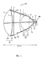
- FIG. 1 shows a simplified side view of an optical lens 100 in accordance with an embodiment of the present invention.
- Lens 100 includes a first lens group 101 (e.g., an achromatic pair (doublet)) optically coupled to a second lens group 103 (e.g., an achromatic pair (doublet)) and separated by a space 108.
- a system aperture stop 106 is provided between first lens group 101 and second lens group 103.
- An imaging lens 114 is optically coupled to second lens group 103 and separated by a space 113, and an image of an object (not shown) is then provided at an imaging focal plane, shown by reference IMA.
- first lens group 101 includes a crown glass 102 and a flint glass 104
- second lens group 103 includes a flint glass 110 and a flint glass 112.
- Aspheric conic surfaces are provided at the front surface of each of the first glasses of the lens groups 101 and 103 (e.g., a front surface 1 of crown glass 102 and a front surface 6 of flint glass 110) to function together with space 108 (e.g., an air gap) to maintain control over chromatic aberrations.
- space 108 e.g., an air gap
- a small air gap exists between crown glass 102 and flint glass 104 of first lens group 101, whereas flint glass 110 and flint glass 112 of second lens group 103 are "cemented" together.
- System stop 106 may include a metal ring, in one example, or an iris (similar to those available in commercial cameras), therefore functioning to restrict light rays transmitted through the optical system and to define the amount of light flux transmitted by the optical system.
- the diameter of system stop 106 is about 38 mm.
- imaging lens 114 provides a final field-flattening effect on the image and otherwise improves (e.g., clarifies, focuses, shortens the focal length, removes aberrations) the final image similar to the functions of a classic meniscus lens.
- lens 100 fast and compact is spacing, which in one example is provided by spaces 108 and 113 (e.g., through a medium of air or other gas), to maintain a roughly constant ray angle through the lens, to the focal plane IMA, tapering in a roughly 45 degree cone.
- Aspheric surfaces 1 and 6 also allow for control over chromatic aberrations (color dispersion) and thus allows for reduction of glass (and hence reduction in mass) between lens groups 101 and 103.
- Lens 100 is also configured to include system stop 106 behind first lens group 101, which reduces the diameter, and therefore mass, of substantially all the system elements.
- a typical achromatic lens is a crown lens and a flint lens
- a flint-flint pair may be referred to as an achromatic doublet in this document since the form is similar.
- optical design software such as, for example, ZEMAX® from ZEMAX Development Corporation of San Diego, California, may be used to assist in describing the various characteristics (e.g., radius, thickness, glass type, diameter, and whether the surface is conic) corresponding to each surface region of each individual element/group within optical system 100.
- ZEMAX software outputs surface data describing these surface characteristics as illustrated in Table 1.
- the surface data for surface OBJ correspond to an object to be imaged (not shown).
- the surface data for surfaces 1-2 and 3-4 correspond to crown glass 102 and flint glass 104, respectively, of first lens group 101.
- the surface data for surface STO correspond to system stop 106.
- the surface data for surfaces 6, 7, and 8 correspond to flint glass 110 and flint glass 112 of second lens group 103.
- the surface data for surfaces 9-10 and IMA correspond to imaging lens 114 and the imaging focal plane, respectively.
- surface 1 of crown glass 102 and surface 6 of flint glass 110 are each provided with low order aspheric surfaces with a non-zero conic constant.
- surface 1 is an ellipsoid and surface 6 is a hyperboloid, both being positive surfaces.
- the present invention provides a lens system with a 38 mm aperture lens and a length (including the relief to the focal plane) of about 49 mm and a mass (of the glass lens elements) of about 61 grams, which is more compact and lightweight than conventional lenses.
- Lenses may be comprised of various applicable materials, including but not limited to glass, such as crown glass type PSK3 and flint glass type SF1 and LAF2, and optical plastic, such as Lexan® commercially available from the General Electric Company.
- glass such as crown glass type PSK3 and flint glass type SF1 and LAF2
- optical plastic such as Lexan® commercially available from the General Electric Company.
- Other surface data values for each individual element/group will become apparent to those of ordinary skill in the art in light of the present disclosure and may therefore be determined through routine experimentation dependent on the overall configuration and positioning of the individual elements/groups within optical system 100 and the quality of the image desired.
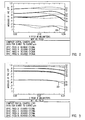
- FIGS. 2 and 3 show a modulation transfer function (MTF) of an example of optical lens 100 of FIG. 1 at f/0.87 and f/2.4, respectively, in accordance with embodiments of the present invention.
- the MTF is a measure of the extent to which a lens, film, etc., can reproduce detail in an image.
- MTF is the spatial analog of frequency response in an electrical system.
- the 2-dimensional Fourier transform of the point spread function is known as the optical transfer function (OTF).
- OTF optical transfer function
- the value of this function along any radius is the Fourier transform of the line spread function in the same direction.
- the MTF is the absolute value of the Fourier transform of the line spread function.
- the MTF of a lens is the ratio of the relative image contrast divided by relative object contrast of an object with sinusoidally varying brightness as a function of spatial frequency.
- the MTF for an ideal lens (ignoring the unavoidable effect of diffraction) is a constant 1 for spatial frequencies from 0 to infinity at every point and direction. For a practical lens it starts near 1 and falls off with increasing spatial frequency, with the MTF of a typical optical system being worse at the edges of the image and best at the center.
- Lines 201 and 301 show the approximate sampling limits (cutoff) for a detector (e.g., of current satellite cameras) having typical 7 ⁇ m pixels.
- the x-axis of the graphs is image height, and each line is at a different spatial frequency, with the solid lines being across one dimension and the dashed lines being across another dimension.
- FIGS. 2 and 3 show the MTF at 10, 20, 30, and 60 line pair (lp)/mm for f/0.87 and f/2.4, respectively.
- the present invention provides a compact and lightweight lens with superior performance characteristics.
- the present invention may be used with small and lightweight sensors for autonomous space vehicles (e.g., with electro-optical systems on a new class of very small nano-scale satellites) to assess other objects in space, with factory machine vision applications such as quality control, with commercial applications such as consumer cameras, cellular telephones, and PDAs, and with robotic applications.
- autonomous space vehicles e.g., with electro-optical systems on a new class of very small nano-scale satellites
- factory machine vision applications such as quality control
- commercial applications such as consumer cameras, cellular telephones, and PDAs
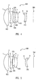
- FIGS. 4, 5 , and 6 comparative examples of an optical lens are shown.
- FIG. 4 shows a lens 400 including a first lens group including a crown glass 402 and a flint glass 404.
- An aperture stop 406 is provided adjacent flint glass 404.
- a second lens group includes a flint glass 408 and a flint glass 410.
- An imaging lens 412 is optically coupled to the second lens group, and an image of an object (not shown) is then provided at an imaging focal plane, shown by reference IMA.
- FIG. 5 shows a lens 500 including a first lens group including a crown glass 502 and a flint glass 504.
- An aperture stop 506 is provided adjacent flint glass 504.
- a second lens group includes a flint glass 508.
- An imaging lens 510 is optically coupled to the second lens group (i.e., flint glass 508), and an image of an object (not shown) is then provided at an imaging focal plane, shown by reference IMA.
- the ZEMAX software outputs surface data describing these surface characteristics as illustrated in Table 3.
- Table 3 ZEMAX Software Output Describing Optical System 500 SURFACE DATA SUMMARY: Surf Type Radius Thickness Glass Diameter Conic OBJ STANDARD Infinity Infinity 0 0 1 STANDARD 15.32647 7 PSK3 24 -0.2071472 2 STANDARD -391.7632 3 24 0 3 STANDARD -28.98024 2 SF1 16 0 4 STANDARD 18.26125 0.9112846 16 0 STO STANDARD Infinity 2.775979 14.9505 0 6 STANDARD 40.1985 4 LAF2 14 -20.90341 7 STANDARD -19.54904 11.64467 14 0 8 STANDARD 16.2611 2 LAF2 12 0 9 STANDARD 10.76643 10 12 0 IMA STANDARD Infinity 14.48255 0
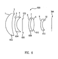
- FIG. 6 shows a lens 600 including a first lens group including a crown glass 602 and a flint glass 604.
- An aperture stop 606 is provided adjacent flint glass 604.
- a second lens group includes a flint glass 608 and a crown glass 610.
- An imaging lens 612 is optically coupled to the second lens group, and an image of an object (not shown) is then provided at an imaging focal plane, shown by reference IMA.
- the ZEMAX software outputs surface data describing these surface characteristics as illustrated in Table 4.
- Table 4 ZEMAX Software Output Describing Optical System 600 SURFACE DATA SUMMARY: Surf Type Radius Thickness Glass Diameter Conic OBJ STANDARD Infinity Infinity 0 0 1 STANDARD 13.46652 7 PSK3 24 -0.3030542 2 STANDARD 35.18615 3 24 0 3 STANDARD 21.67603 2 SF1 16 0 4 STANDARD 9.140547 6.190861 16 0 STO STANDARD Infinity 6.843253 14.00481 0 6 STANDARD 17.72794 2 SF1 14 -1.695101 7 STANDARD 14.60109 3.971766 BK7 14 0 8 STANDARD -17.8388 6.91552 14 0 9 STANDARD 13.65838 2 LAF2 12 0 10 STANDARD 8.195292 10 12 0 IMA STANDARD Infinity 14.78756 0
- Lenses may be comprised of various applicable materials, including but not limited to glass, such as crown glass type PSK3 and flint glass type SF1 and LAF2, and optical plastic, such as Lexan® commercially available from the General Electric Company.
- glass such as crown glass type PSK3 and flint glass type SF1 and LAF2
- optical plastic such as Lexan® commercially available from the General Electric Company.
- Other surface data values for each individual element/group will become apparent to those of ordinary skill in the art in light of the present disclosure and may therefore be determined through routine experimentation dependent on the overall configuration and positioning of the individual elements/groups within optical systems 400, 500, and 600, and the quality of the image desired. Surfaces have been referenced with numerals 1 through 10, STO, and IMA.
Landscapes
- Physics & Mathematics (AREA)
- General Physics & Mathematics (AREA)
- Optics & Photonics (AREA)
- Lenses (AREA)
Description
- The present invention relates generally to optics and, more particularly, to a compact and lightweight lens and method of using the same.
- Digital camera lenses are used for various applications, including but not limited to imaging sensors for small satellites, and consumer electronics such as small digital cameras for cellular telephones and PDAs.
- Lenses are typically among the largest and heaviest components of small cameras and sensors, some weighing approximately 140 grams. However, shortening the length of a lens to reduce size or lowering the amount of glass to reduce mass typically have an adverse impact on the lens performance, for example reducing the ability to create images without blurring.
- Thus, a compact and lightweight lens that also provides high-performance is highly desirable.
- The document
US 6 111 703 A discloses relevant prior art. - The present invention provides a digital camera comprising a compact and lightweight but high-performance lens according to
claim 1 and method of using the same according toclaim 6. The lens includes five optics, two of which incorporate low order aspheric surfaces with a non-zero conic constant. - Advantageously, the present invention provides a digital camera comprising a highly compact and lightweight lens that provides high performance, collecting more light than many available commercial lenses. The present invention provides excellent imagery for satellite digital cameras or other high-precision digital photography or video applications, such-as factory machine vision, and for commercial applications such as for cellular telephones and PDAs.
- The scope of the invention is defined by the claims, which are incorporated into this section by reference. A more complete understanding of embodiments of the present invention will be afforded to those skilled in the art, as well as a realization of additional advantages thereof, by a consideration of the following detailed description of one or more embodiments. Reference will be made to the appended sheets of drawings that will first be described briefly.
-
-
FIG. 1 shows a simplified side view of an optical lens in accordance with an embodiment of the present invention. -
FIG. 2 shows a modulation transfer function (MTF) of the optical lens at f/0.9 in accordance with an embodiment of the present invention. -
FIG. 3 shows a modulation transfer function (MTF) of the optical lens at f/2.4 in accordance with an embodiment of the present invention. -
FIGS. 4, 5 , and6 show different comparative examples of an optical lens. - Embodiments of the present invention and their advantages are best understood by referring to the detailed description that follows. It should be appreciated that like reference numerals are used to identify like elements illustrated in one or more of the figures. It should also be appreciated that the figures may not be necessarily drawn to scale.
- The present invention provides a compact, lightweight, and high-performance lens and method of using the same. In one embodiment, the lens of the present invention includes five optics, two of which incorporate conics. In one example, a 38 mm aperture lens having a length (including the relief to the focal plane) of about 49 mm and a mass (of the glass lens elements) of about 61 grams may be constructed that is fast (good light gathering), operating well at f/0.9 and being diffraction limited in the visible at f/8.
-
FIG. 1 shows a simplified side view of anoptical lens 100 in accordance with an embodiment of the present invention.Lens 100 includes a first lens group 101 (e.g., an achromatic pair (doublet)) optically coupled to a second lens group 103 (e.g., an achromatic pair (doublet)) and separated by aspace 108. Asystem aperture stop 106 is provided betweenfirst lens group 101 andsecond lens group 103. Animaging lens 114 is optically coupled tosecond lens group 103 and separated by aspace 113, and an image of an object (not shown) is then provided at an imaging focal plane, shown by reference IMA. - In one example,
first lens group 101 includes acrown glass 102 and aflint glass 104, andsecond lens group 103 includes aflint glass 110 and aflint glass 112. Aspheric conic surfaces are provided at the front surface of each of the first glasses of thelens groups 101 and 103 (e.g., afront surface 1 ofcrown glass 102 and afront surface 6 of flint glass 110) to function together with space 108 (e.g., an air gap) to maintain control over chromatic aberrations. In one example, a small air gap exists betweencrown glass 102 andflint glass 104 offirst lens group 101, whereasflint glass 110 andflint glass 112 ofsecond lens group 103 are "cemented" together. -
System stop 106 may include a metal ring, in one example, or an iris (similar to those available in commercial cameras), therefore functioning to restrict light rays transmitted through the optical system and to define the amount of light flux transmitted by the optical system. In one example, the diameter ofsystem stop 106 is about 38 mm. - In one example,
imaging lens 114 provides a final field-flattening effect on the image and otherwise improves (e.g., clarifies, focuses, shortens the focal length, removes aberrations) the final image similar to the functions of a classic meniscus lens. - One aspect of making
lens 100 fast and compact is spacing, which in one example is provided byspaces 108 and 113 (e.g., through a medium of air or other gas), to maintain a roughly constant ray angle through the lens, to the focal plane IMA, tapering in a roughly 45 degree cone.Aspheric surfaces lens groups Lens 100 is also configured to includesystem stop 106 behindfirst lens group 101, which reduces the diameter, and therefore mass, of substantially all the system elements. - It should be noted that while a typical achromatic lens is a crown lens and a flint lens, a flint-flint pair may be referred to as an achromatic doublet in this document since the form is similar.
- Commonly available optical design software such as, for example, ZEMAX® from ZEMAX Development Corporation of San Diego, California, may be used to assist in describing the various characteristics (e.g., radius, thickness, glass type, diameter, and whether the surface is conic) corresponding to each surface region of each individual element/group within
optical system 100. In the example configuration shown inFIG. 1 , the ZEMAX software outputs surface data describing these surface characteristics as illustrated in Table 1.TABLE 1 ZEMAX Software Output Describing Optical System 100GENERAL LENS DATA: Surfaces : 11 Stop : 5 System Aperture : Entrance Pupil Diameter = 38 Effective Focal Length : 33.37436 (in air at system temperature and pressure) Total Track : 49.40845 Image Space F/# : 0.8782726 Stop Radius : 14.23872 Paraxial Image Height : 4.242641 Field Type : Paraxial Image height in Millimeters Maximum Field : 4.242641 Primary Wave : 0.5875618 Lens Units : Millimeters Fields : 5 Field Type: Paraxial Image height in Millimeters # X-Value Y-Value Weight 1 0.000000 0.000000 3.000000 2 0.000000 2.000000 1.000000 3 2.000000 2.000000 1.000000 4 0.000000 3.000000 1.000000 5 3.000000 3.000000 1.000000 Wavelengths : 3 Units: µm # Value Weight 1 0.486133 1.000000 2 0.587562 1.000000 3 0.656273 1.000000 SURFACE DATA SUMMARY: Surf Type Radius Thickness Glass Diameter Conic OBJ STANDARD Infinity Infinity 0 0 1 STANDARD 22.81299 12.96409 PSK3 39.15649 -0.4562032 2 STANDARD -66.62921 0.4783454 38.61559 0 3 STANDARD -58.04508 0.7271603 SF1 37.84834 0 4 STANDARD 750.8621 1.210387 35.54713 0 STO STANDARD Infinity 8.921799 34.55775 0 6 STANDARD 40.10207 0.9818026 SF1 26.80649 -2.897021 7 STANDARD 12.00049 13.44143 LAF2 22.70695 0 8 STANDARD -91.26881 6.413307 19.66926 0 9 STANDARD -12.6565 3.257546 LAF2 10.45281 0 10 STANDARD -32.03257 1.012579 9.600586 0 IMA STANDARD Infinity 9.438423 0 INDEX OF REFRACTION DATA: System Temperature: 20.00 System Pressure : 1.00 Surf Glass Temp Pres 0.486133 0.587562 0.656273 1 PSK3 20.00 1.00 1.55835488 1.55232187 1.54965090 3 SF1 20.00 1.00 1.73462020 1.71735985 1.71031348 6 SF1 20.00 1.00 1.73462020 1.71735985 1.71031348 7 LAF2 20.00 1.00 1.75568493 1.74400238 1.73904801 9 LAF2 20.00 1.00 1.75568493 1.74400238 1.73904801 ELEMENT VOLUME DATA: Surface Volume (cc) Density (g//cc) Mass (g) Element surf 1 to 2 8.325991 2.910000 24.228633 Element surf 3 to 4 2.717820 4.460000 12.121477 Element surf 6 to 7 1.571076 4.460000 7.006997 Element surf 7 to 8 3.945672 4.340000 17.124215 Element surf 9 to 10 0.309327 4.340000 1.342480 Total Mass: 61.823802 - The surface data for surface OBJ (object) correspond to an object to be imaged (not shown). The surface data for surfaces 1-2 and 3-4 correspond to
crown glass 102 andflint glass 104, respectively, offirst lens group 101. The surface data for surface STO (stop) correspond tosystem stop 106. The surface data forsurfaces flint glass 110 andflint glass 112 ofsecond lens group 103. The surface data for surfaces 9-10 and IMA correspond toimaging lens 114 and the imaging focal plane, respectively. - In one example, as described above,
surface 1 ofcrown glass 102 andsurface 6 offlint glass 110 are each provided with low order aspheric surfaces with a non-zero conic constant. In one example,surface 1 is an ellipsoid andsurface 6 is a hyperboloid, both being positive surfaces. - An air gap exists between
surfaces - In one example, as shown by the thickness of the elements in the surface data summary and the mass of the elements in the element volume data, the present invention provides a lens system with a 38 mm aperture lens and a length (including the relief to the focal plane) of about 49 mm and a mass (of the glass lens elements) of about 61 grams, which is more compact and lightweight than conventional lenses.
- The specific nomenclature representing the shapes, compositions, and definitions of the elements as presented in Table 1 follow standards as set forth in the ZEMAX manual. Lenses may be comprised of various applicable materials, including but not limited to glass, such as crown glass type PSK3 and flint glass type SF1 and LAF2, and optical plastic, such as Lexan® commercially available from the General Electric Company. Other surface data values for each individual element/group will become apparent to those of ordinary skill in the art in light of the present disclosure and may therefore be determined through routine experimentation dependent on the overall configuration and positioning of the individual elements/groups within
optical system 100 and the quality of the image desired. -
FIGS. 2 and 3 show a modulation transfer function (MTF) of an example ofoptical lens 100 ofFIG. 1 at f/0.87 and f/2.4, respectively, in accordance with embodiments of the present invention. The MTF is a measure of the extent to which a lens, film, etc., can reproduce detail in an image. MTF is the spatial analog of frequency response in an electrical system. - The 2-dimensional Fourier transform of the point spread function is known as the optical transfer function (OTF). The value of this function along any radius is the Fourier transform of the line spread function in the same direction. The MTF is the absolute value of the Fourier transform of the line spread function.
- Equivalently, the MTF of a lens is the ratio of the relative image contrast divided by relative object contrast of an object with sinusoidally varying brightness as a function of spatial frequency. The MTF for an ideal lens (ignoring the unavoidable effect of diffraction) is a constant 1 for spatial frequencies from 0 to infinity at every point and direction. For a practical lens it starts near 1 and falls off with increasing spatial frequency, with the MTF of a typical optical system being worse at the edges of the image and best at the center.
-
Lines FIGS. 2 and 3 show the MTF at 10, 20, 30, and 60 line pair (lp)/mm for f/0.87 and f/2.4, respectively. - Advantageously, the present invention provides a compact and lightweight lens with superior performance characteristics. In one example, the present invention may be used with small and lightweight sensors for autonomous space vehicles (e.g., with electro-optical systems on a new class of very small nano-scale satellites) to assess other objects in space, with factory machine vision applications such as quality control, with commercial applications such as consumer cameras, cellular telephones, and PDAs, and with robotic applications.
- Referring now to
FIGS. 4, 5 , and6 , comparative examples of an optical lens are shown. -
FIG. 4 shows alens 400 including a first lens group including acrown glass 402 and aflint glass 404. Anaperture stop 406 is providedadjacent flint glass 404. A second lens group includes aflint glass 408 and aflint glass 410. Animaging lens 412 is optically coupled to the second lens group, and an image of an object (not shown) is then provided at an imaging focal plane, shown by reference IMA. - In the configuration shown in
FIG. 4 , the ZEMAX software outputs surface data describing these surface characteristics as illustrated in Table 2.TABLE 2 ZEMAX Software Output Describing Optical System 400 GENERAL LENS DATA: Surfaces : 11 Stop : 5 System Aperture : Entrance Pupil Diameter = 18 Glass Catalogs : SCHOTT Ray Aiming : Off Apodization : Uniform, factor = 0.00000E+000 Temperature (C) : 2.00000E+001 Pressure (ATM) : 1.00000E+000 Effective Focal Length pressure) : 36.01015 (in air at system temperature and Effective Focal Length : 36.01015 (in image space) Back Focal Length : 10.0778 Total Track : 43.01304 Image Space F/# : 2.000564 Paraxial Working F/# : 2.000564 Working F/# : 1.994172 Image Space NA : 0.2424713 Object Space NA : 9e-010 Stop Radius : 6.524289 Paraxial Image Height : 7.204498 Paraxial Magnification : 0 Entrance Pupil Diameter : 18 Entrance Pupil Position : 16.83506 Exit Pupil Diameter : 11.1336 Exit Pupil Position : -22.19567 Field Type : Angle in degrees Maximum Field : 11.31371 Primary Wave : 0.455 Lens Units : Millimeters Angular Magnification : 1.616728 Fields : 3 Field Type: Angle in degrees # X-Value Y-Value Weight 1 0.000000 0.000000 1.000000 2 0.000000 8.000000 5.000000 3 8.000000 8.000000 10.000000 Wavelengths : 6 Units: µm # Value Weight 1 0.455000 20.000000 2 0.505000 20.000000 3 0.555000 20.000000 4 0.605000 20.000000 5 0.655000 12.000000 6 0.700000 7.000000 SURFACE DATA SUMMARY: Surf Type Radius Thickness Glass Diameter Conic OBJ STANDARD Infinity Infinity 0 0 1 STANDARD 15.44311 7 PSK3 24 -0.2309592 2 STANDARD -160.3136 3 24 0 3 STANDARD -26.32848 2 SF1 16 0 4 STANDARD 16.28292 2.128283 16 0 STO STANDARD Infinity 0.7595053 15.85363 0 6 STANDARD 20.77184 2 SF1 14 -1.327658 7 STANDARD 19.19067 4 LAF2 14 0 8 STANDARD -21.81758 10.12526 14 0 9 STANDARD -12.2472 2 LAF2 12 0 10 STANDARD -25.19672 10 12 0 IMA STANDARD Infinity 14.40202 0 ELEMENT VOLUME DATA: Volume (cc) Density (g/cc) Mass (g) Element surf 1 to 2 1.910044 2.910000 5.558227 Element surf 3 to 4 0.732597 4.460000 3.267381 Element surf 6 to 7 0.318207 4.460000 1.419202 Element surf 7 to 8 0.427218 4.340000 1.854125 Element surf 9 to 10 0.272184 4.340000 1.181278 Total Mass: 13.280214 -
FIG. 5 shows alens 500 including a first lens group including acrown glass 502 and aflint glass 504. Anaperture stop 506 is providedadjacent flint glass 504. A second lens group includes aflint glass 508. Animaging lens 510 is optically coupled to the second lens group (i.e., flint glass 508), and an image of an object (not shown) is then provided at an imaging focal plane, shown by reference IMA. - In the configuration shown in
FIG. 5 , the ZEMAX software outputs surface data describing these surface characteristics as illustrated in Table 3.TABLE 3 ZEMAX Software Output Describing Optical System 500SURFACE DATA SUMMARY: Surf Type Radius Thickness Glass Diameter Conic OBJ STANDARD Infinity Infinity 0 0 1 STANDARD 15.32647 7 PSK3 24 -0.2071472 2 STANDARD -391.7632 3 24 0 3 STANDARD -28.98024 2 SF1 16 0 4 STANDARD 18.26125 0.9112846 16 0 STO STANDARD Infinity 2.775979 14.9505 0 6 STANDARD 40.1985 4 LAF2 14 -20.90341 7 STANDARD -19.54904 11.64467 14 0 8 STANDARD 16.2611 2 LAF2 12 0 9 STANDARD 10.76643 10 12 0 IMA STANDARD Infinity 14.48255 0 -
FIG. 6 shows alens 600 including a first lens group including acrown glass 602 and aflint glass 604. Anaperture stop 606 is providedadjacent flint glass 604. A second lens group includes aflint glass 608 and acrown glass 610. Animaging lens 612 is optically coupled to the second lens group, and an image of an object (not shown) is then provided at an imaging focal plane, shown by reference IMA. - In the configuration shown in
FIG. 6 , the ZEMAX software outputs surface data describing these surface characteristics as illustrated in Table 4.TABLE 4 ZEMAX Software Output Describing Optical System 600SURFACE DATA SUMMARY: Surf Type Radius Thickness Glass Diameter Conic OBJ STANDARD Infinity Infinity 0 0 1 STANDARD 13.46652 7 PSK3 24 -0.3030542 2 STANDARD 35.18615 3 24 0 3 STANDARD 21.67603 2 SF1 16 0 4 STANDARD 9.140547 6.190861 16 0 STO STANDARD Infinity 6.843253 14.00481 0 6 STANDARD 17.72794 2 SF1 14 -1.695101 7 STANDARD 14.60109 3.971766 BK7 14 0 8 STANDARD -17.8388 6.91552 14 0 9 STANDARD 13.65838 2 LAF2 12 0 10 STANDARD 8.195292 10 12 0 IMA STANDARD Infinity 14.78756 0 - The specific nomenclature representing the shapes, compositions, and definitions of the elements as presented in Tables 2, 3, and 4 follow standards as set forth in the ZEMAX manual. Lenses may be comprised of various applicable materials, including but not limited to glass, such as crown glass type PSK3 and flint glass type SF1 and LAF2, and optical plastic, such as Lexan® commercially available from the General Electric Company. Other surface data values for each individual element/group will become apparent to those of ordinary skill in the art in light of the present disclosure and may therefore be determined through routine experimentation dependent on the overall configuration and positioning of the individual elements/groups within
optical systems numerals 1 through 10, STO, and IMA. - The embodiment described above illustrates but does not limit the invention. It should also be understood that numerous modifications and variations are possible in accordance with the principles of the present invention. For example, variation or adjustment in tilt or centering of lenses or other elements may occur according to desired image quality. Accordingly, the scope of the invention is defined only by the following claims.
Claims (6)
- A digital camera comprising an optical lens, consisting of:a crown lens (102);a first flint lens (104) optically coupled to the crown lens;an aperture stop (106) adjacent the first flint lens;a second flint lens (110) optically coupled to the aperture stop;a first air gap (108) between the aperture stop and the second flint lens;a third flint lens (112) coupled to the second flint lens; andan imaging lens (114) optically coupled to the third flint lens,wherein the crown lens and the first flint lens form a first achromatic pair and wherein the second flint lens and the third flint lens form a second achromatic pair,wherein the aperture stop is between the first flint lens and the second flint lens,a second air gap (113) between the third flint lens and the imaging lens;a third air gap between the imaging lens and an imaging focal plane;characterised in that the crown lens (102) has a first aspheric surface on its object-side surface (1); and the second flint lens (110) has a second aspheric surface on its object-side surface (6); for controlling chromatic aberration.
- The camera of Claim 1, wherein the mass of the crown lens, the first flint lens, the second flint lens, the third flint lens, and the imaging lens is less than 62 grams.
- The camera of Claim 1, wherein the aperture stop has a diameter of about 38 mm.
- The camera of Claim 1, wherein the third flint lens is cemented to a surface of the second flint lens.
- The camera of Claim 1, wherein a distance between the first aspheric surface and the imaging focal plane is less than 50 mm.
- A method of imaging using a camera according to any of claims 1-5, wherein a roughly constant ray angle through the lens, to the focal plane IMA, tapering in a roughly 45 degree cone is maintained.
Applications Claiming Priority (2)
| Application Number | Priority Date | Filing Date | Title |
|---|---|---|---|
| US11/139,312 US7075736B1 (en) | 2005-05-27 | 2005-05-27 | Compact and lightweight digital camera lens |
| PCT/US2006/015705 WO2006130275A1 (en) | 2005-05-27 | 2006-04-26 | Compact and lightweight digital camera lens |
Publications (2)
| Publication Number | Publication Date |
|---|---|
| EP1883847A1 EP1883847A1 (en) | 2008-02-06 |
| EP1883847B1 true EP1883847B1 (en) | 2014-10-01 |
Family
ID=36644125
Family Applications (1)
| Application Number | Title | Priority Date | Filing Date |
|---|---|---|---|
| EP06758598.4A Not-in-force EP1883847B1 (en) | 2005-05-27 | 2006-04-26 | Digital camera with compact and lightweight lens |
Country Status (5)
| Country | Link |
|---|---|
| US (1) | US7075736B1 (en) |
| EP (1) | EP1883847B1 (en) |
| JP (1) | JP2008542821A (en) |
| CA (1) | CA2603880C (en) |
| WO (1) | WO2006130275A1 (en) |
Families Citing this family (11)
| Publication number | Priority date | Publication date | Assignee | Title |
|---|---|---|---|---|
| US7548374B2 (en) * | 2006-06-07 | 2009-06-16 | Genie Lens Technologies, Llc | Packaging system providing spatial or focusing gaps between lenticular lenses and paired interlaced images |
| US7457039B2 (en) * | 2006-06-07 | 2008-11-25 | Genie Lens Technologies, Llc | Lenticular display system with a lens sheet spaced apart from a paired interlaced image |
| US7607616B2 (en) * | 2006-11-29 | 2009-10-27 | The Boeing Company | Docking device |
| US7762677B2 (en) * | 2007-10-15 | 2010-07-27 | The Boeing Company | Optical system with inter-lens baffles |
| US8253780B2 (en) * | 2008-03-04 | 2012-08-28 | Genie Lens Technology, LLC | 3D display system using a lenticular lens array variably spaced apart from a display screen |
| JP5201679B2 (en) | 2008-12-25 | 2013-06-05 | 株式会社オプトロジック | Imaging lens |
| JP5095662B2 (en) | 2009-03-31 | 2012-12-12 | カンタツ株式会社 | Imaging lens for solid-state imaging device |
| TWI421557B (en) | 2009-07-14 | 2014-01-01 | Largan Precision Co Ltd | Imaging lens system |
| WO2012160831A1 (en) * | 2011-05-26 | 2012-11-29 | 富士フイルム株式会社 | Imaging lens and imaging device equipped with imaging lens |
| CN105445902B (en) * | 2015-04-30 | 2017-12-08 | 深圳爱酷智能科技有限公司 | Imaging lens, iris imaging module and iris identification device |
| CN110989142B (en) * | 2019-12-30 | 2021-07-06 | 中国科学院长春光学精密机械与物理研究所 | Preposed common-caliber dual-waveband achromatic lens of Fourier transform imaging spectrometer |
Citations (2)
| Publication number | Priority date | Publication date | Assignee | Title |
|---|---|---|---|---|
| US6111703A (en) * | 1997-12-17 | 2000-08-29 | Olympus Optical Co., Ltd. | Image pickup optical system |
| JP2005234068A (en) * | 2004-02-18 | 2005-09-02 | Fujinon Corp | Image reading lens and image reader |
Family Cites Families (6)
| Publication number | Priority date | Publication date | Assignee | Title |
|---|---|---|---|---|
| US3022708A (en) * | 1957-12-16 | 1962-02-27 | James G Baker | Correcting optical system |
| US6078433A (en) * | 1998-01-05 | 2000-06-20 | Intel Corporation | Zoom lens system |
| JP4285957B2 (en) * | 2002-08-29 | 2009-06-24 | オリンパス株式会社 | Zoom lens and electronic imaging apparatus having the same |
| US7440195B2 (en) * | 2003-03-31 | 2008-10-21 | Konica Minolta Camera, Inc. | Zoom lens system and imaging device having the same |
| JP2004348082A (en) * | 2003-05-26 | 2004-12-09 | Olympus Corp | Optical path bending optical system |
| JP4561634B2 (en) * | 2003-11-13 | 2010-10-13 | コニカミノルタオプト株式会社 | Imaging lens and imaging apparatus |
-
2005
- 2005-05-27 US US11/139,312 patent/US7075736B1/en not_active Expired - Fee Related
-
2006
- 2006-04-26 CA CA2603880A patent/CA2603880C/en not_active Expired - Fee Related
- 2006-04-26 JP JP2008513495A patent/JP2008542821A/en active Pending
- 2006-04-26 WO PCT/US2006/015705 patent/WO2006130275A1/en active Application Filing
- 2006-04-26 EP EP06758598.4A patent/EP1883847B1/en not_active Not-in-force
Patent Citations (2)
| Publication number | Priority date | Publication date | Assignee | Title |
|---|---|---|---|---|
| US6111703A (en) * | 1997-12-17 | 2000-08-29 | Olympus Optical Co., Ltd. | Image pickup optical system |
| JP2005234068A (en) * | 2004-02-18 | 2005-09-02 | Fujinon Corp | Image reading lens and image reader |
Also Published As
| Publication number | Publication date |
|---|---|
| CA2603880C (en) | 2016-12-20 |
| WO2006130275A1 (en) | 2006-12-07 |
| JP2008542821A (en) | 2008-11-27 |
| US7075736B1 (en) | 2006-07-11 |
| EP1883847A1 (en) | 2008-02-06 |
| CA2603880A1 (en) | 2006-12-07 |
Similar Documents
| Publication | Publication Date | Title |
|---|---|---|
| EP1883847B1 (en) | Digital camera with compact and lightweight lens | |
| EP2138883B1 (en) | Imaging lens of the retrofocus type having three lens groups | |
| CN111458836B (en) | Image capturing optical lens assembly, image capturing device and electronic device | |
| CN112394497B (en) | Optical camera lens assembly, image capturing device and electronic device | |
| EP0566073B1 (en) | Zoom lens assembly | |
| EP2921896B1 (en) | Zoom lens and image pickup apparatus having the same | |
| US10197893B2 (en) | Rear converter lens and imaging apparatus | |
| CN106597647B (en) | Optical system and imaging apparatus including the same | |
| US9952405B2 (en) | Imaging lens and imaging apparatus | |
| CN108535834B (en) | Optical lens and imaging apparatus | |
| CN110716284B (en) | Imaging optical lens assembly, image capturing device and electronic device | |
| EP2637056A1 (en) | Fish Eye Lens System and Photographing Apparatus Including the Same | |
| CN111665613B (en) | Image capturing optical lens assembly, image capturing device and electronic device | |
| US11029488B2 (en) | Rear converter lens and imaging apparatus | |
| CN108535837B (en) | Imaging lens and imaging device | |
| US10698182B2 (en) | Imaging lens and imaging apparatus | |
| CN111948786A (en) | Optical image capturing lens assembly, image capturing device and electronic device | |
| EP3121633B1 (en) | Imaging optical system, camera device, and portable information terminal apparatus | |
| JP3295027B2 (en) | Retrofocus type large aperture ratio wide-angle lens | |
| US10948690B2 (en) | Photographing optical lens assembly, image capturing unit and electronic device | |
| US20220011542A1 (en) | Imaging lens and imaging apparatus | |
| CN114063245B (en) | Six-piece wide-angle lens group | |
| CN114127608B (en) | Imaging lens and imaging device | |
| WO2013157248A1 (en) | Variable magnification optical system, and imaging device | |
| KR101722565B1 (en) | Subminiature wide-angle image pickup lens system |
Legal Events
| Date | Code | Title | Description |
|---|---|---|---|
| PUAI | Public reference made under article 153(3) epc to a published international application that has entered the european phase |
Free format text: ORIGINAL CODE: 0009012 |
|
| 17P | Request for examination filed |
Effective date: 20071024 |
|
| AK | Designated contracting states |
Kind code of ref document: A1 Designated state(s): AT BE BG CH CY CZ DE DK EE ES FI FR GB GR HU IE IS IT LI LT LU LV MC NL PL PT RO SE SI SK TR |
|
| DAX | Request for extension of the european patent (deleted) | ||
| 17Q | First examination report despatched |
Effective date: 20100527 |
|
| REG | Reference to a national code |
Ref country code: DE Ref legal event code: R079 Ref document number: 602006043207 Country of ref document: DE Free format text: PREVIOUS MAIN CLASS: G02B0013000000 Ipc: G02B0009340000 |
|
| GRAP | Despatch of communication of intention to grant a patent |
Free format text: ORIGINAL CODE: EPIDOSNIGR1 |
|
| INTG | Intention to grant announced |
Effective date: 20140509 |
|
| RIC1 | Information provided on ipc code assigned before grant |
Ipc: G02B 13/00 20060101ALI20140429BHEP Ipc: G02B 13/18 20060101ALI20140429BHEP Ipc: G02B 9/34 20060101AFI20140429BHEP |
|
| GRAS | Grant fee paid |
Free format text: ORIGINAL CODE: EPIDOSNIGR3 |
|
| GRAA | (expected) grant |
Free format text: ORIGINAL CODE: 0009210 |
|
| AK | Designated contracting states |
Kind code of ref document: B1 Designated state(s): AT BE BG CH CY CZ DE DK EE ES FI FR GB GR HU IE IS IT LI LT LU LV MC NL PL PT RO SE SI SK TR |
|
| REG | Reference to a national code |
Ref country code: GB Ref legal event code: FG4D |
|
| REG | Reference to a national code |
Ref country code: AT Ref legal event code: REF Ref document number: 689800 Country of ref document: AT Kind code of ref document: T Effective date: 20141015 Ref country code: CH Ref legal event code: EP |
|
| REG | Reference to a national code |
Ref country code: IE Ref legal event code: FG4D |
|
| REG | Reference to a national code |
Ref country code: DE Ref legal event code: R096 Ref document number: 602006043207 Country of ref document: DE Effective date: 20141106 |
|
| REG | Reference to a national code |
Ref country code: NL Ref legal event code: VDEP Effective date: 20141001 |
|
| REG | Reference to a national code |
Ref country code: AT Ref legal event code: MK05 Ref document number: 689800 Country of ref document: AT Kind code of ref document: T Effective date: 20141001 |
|
| REG | Reference to a national code |
Ref country code: LT Ref legal event code: MG4D |
|
| PG25 | Lapsed in a contracting state [announced via postgrant information from national office to epo] |
Ref country code: NL Free format text: LAPSE BECAUSE OF FAILURE TO SUBMIT A TRANSLATION OF THE DESCRIPTION OR TO PAY THE FEE WITHIN THE PRESCRIBED TIME-LIMIT Effective date: 20141001 |
|
| REG | Reference to a national code |
Ref country code: FR Ref legal event code: PLFP Year of fee payment: 10 |
|
| PG25 | Lapsed in a contracting state [announced via postgrant information from national office to epo] |
Ref country code: PT Free format text: LAPSE BECAUSE OF FAILURE TO SUBMIT A TRANSLATION OF THE DESCRIPTION OR TO PAY THE FEE WITHIN THE PRESCRIBED TIME-LIMIT Effective date: 20150202 Ref country code: IS Free format text: LAPSE BECAUSE OF FAILURE TO SUBMIT A TRANSLATION OF THE DESCRIPTION OR TO PAY THE FEE WITHIN THE PRESCRIBED TIME-LIMIT Effective date: 20150201 Ref country code: ES Free format text: LAPSE BECAUSE OF FAILURE TO SUBMIT A TRANSLATION OF THE DESCRIPTION OR TO PAY THE FEE WITHIN THE PRESCRIBED TIME-LIMIT Effective date: 20141001 Ref country code: CZ Free format text: LAPSE BECAUSE OF FAILURE TO SUBMIT A TRANSLATION OF THE DESCRIPTION OR TO PAY THE FEE WITHIN THE PRESCRIBED TIME-LIMIT Effective date: 20141001 Ref country code: FI Free format text: LAPSE BECAUSE OF FAILURE TO SUBMIT A TRANSLATION OF THE DESCRIPTION OR TO PAY THE FEE WITHIN THE PRESCRIBED TIME-LIMIT Effective date: 20141001 Ref country code: LT Free format text: LAPSE BECAUSE OF FAILURE TO SUBMIT A TRANSLATION OF THE DESCRIPTION OR TO PAY THE FEE WITHIN THE PRESCRIBED TIME-LIMIT Effective date: 20141001 |
|
| PG25 | Lapsed in a contracting state [announced via postgrant information from national office to epo] |
Ref country code: LV Free format text: LAPSE BECAUSE OF FAILURE TO SUBMIT A TRANSLATION OF THE DESCRIPTION OR TO PAY THE FEE WITHIN THE PRESCRIBED TIME-LIMIT Effective date: 20141001 Ref country code: SE Free format text: LAPSE BECAUSE OF FAILURE TO SUBMIT A TRANSLATION OF THE DESCRIPTION OR TO PAY THE FEE WITHIN THE PRESCRIBED TIME-LIMIT Effective date: 20141001 Ref country code: GR Free format text: LAPSE BECAUSE OF FAILURE TO SUBMIT A TRANSLATION OF THE DESCRIPTION OR TO PAY THE FEE WITHIN THE PRESCRIBED TIME-LIMIT Effective date: 20150102 Ref country code: CY Free format text: LAPSE BECAUSE OF FAILURE TO SUBMIT A TRANSLATION OF THE DESCRIPTION OR TO PAY THE FEE WITHIN THE PRESCRIBED TIME-LIMIT Effective date: 20141001 Ref country code: AT Free format text: LAPSE BECAUSE OF FAILURE TO SUBMIT A TRANSLATION OF THE DESCRIPTION OR TO PAY THE FEE WITHIN THE PRESCRIBED TIME-LIMIT Effective date: 20141001 Ref country code: PL Free format text: LAPSE BECAUSE OF FAILURE TO SUBMIT A TRANSLATION OF THE DESCRIPTION OR TO PAY THE FEE WITHIN THE PRESCRIBED TIME-LIMIT Effective date: 20141001 |
|
| REG | Reference to a national code |
Ref country code: DE Ref legal event code: R097 Ref document number: 602006043207 Country of ref document: DE |
|
| PG25 | Lapsed in a contracting state [announced via postgrant information from national office to epo] |
Ref country code: SK Free format text: LAPSE BECAUSE OF FAILURE TO SUBMIT A TRANSLATION OF THE DESCRIPTION OR TO PAY THE FEE WITHIN THE PRESCRIBED TIME-LIMIT Effective date: 20141001 Ref country code: EE Free format text: LAPSE BECAUSE OF FAILURE TO SUBMIT A TRANSLATION OF THE DESCRIPTION OR TO PAY THE FEE WITHIN THE PRESCRIBED TIME-LIMIT Effective date: 20141001 Ref country code: DK Free format text: LAPSE BECAUSE OF FAILURE TO SUBMIT A TRANSLATION OF THE DESCRIPTION OR TO PAY THE FEE WITHIN THE PRESCRIBED TIME-LIMIT Effective date: 20141001 Ref country code: RO Free format text: LAPSE BECAUSE OF FAILURE TO SUBMIT A TRANSLATION OF THE DESCRIPTION OR TO PAY THE FEE WITHIN THE PRESCRIBED TIME-LIMIT Effective date: 20141001 |
|
| PLBE | No opposition filed within time limit |
Free format text: ORIGINAL CODE: 0009261 |
|
| STAA | Information on the status of an ep patent application or granted ep patent |
Free format text: STATUS: NO OPPOSITION FILED WITHIN TIME LIMIT |
|
| PG25 | Lapsed in a contracting state [announced via postgrant information from national office to epo] |
Ref country code: IT Free format text: LAPSE BECAUSE OF FAILURE TO SUBMIT A TRANSLATION OF THE DESCRIPTION OR TO PAY THE FEE WITHIN THE PRESCRIBED TIME-LIMIT Effective date: 20141001 |
|
| 26N | No opposition filed |
Effective date: 20150702 |
|
| PG25 | Lapsed in a contracting state [announced via postgrant information from national office to epo] |
Ref country code: LU Free format text: LAPSE BECAUSE OF FAILURE TO SUBMIT A TRANSLATION OF THE DESCRIPTION OR TO PAY THE FEE WITHIN THE PRESCRIBED TIME-LIMIT Effective date: 20150426 Ref country code: MC Free format text: LAPSE BECAUSE OF FAILURE TO SUBMIT A TRANSLATION OF THE DESCRIPTION OR TO PAY THE FEE WITHIN THE PRESCRIBED TIME-LIMIT Effective date: 20141001 |
|
| REG | Reference to a national code |
Ref country code: CH Ref legal event code: PL |
|
| REG | Reference to a national code |
Ref country code: IE Ref legal event code: MM4A |
|
| PG25 | Lapsed in a contracting state [announced via postgrant information from national office to epo] |
Ref country code: CH Free format text: LAPSE BECAUSE OF NON-PAYMENT OF DUE FEES Effective date: 20150430 Ref country code: LI Free format text: LAPSE BECAUSE OF NON-PAYMENT OF DUE FEES Effective date: 20150430 |
|
| PG25 | Lapsed in a contracting state [announced via postgrant information from national office to epo] |
Ref country code: SI Free format text: LAPSE BECAUSE OF FAILURE TO SUBMIT A TRANSLATION OF THE DESCRIPTION OR TO PAY THE FEE WITHIN THE PRESCRIBED TIME-LIMIT Effective date: 20141001 |
|
| REG | Reference to a national code |
Ref country code: FR Ref legal event code: PLFP Year of fee payment: 11 |
|
| PG25 | Lapsed in a contracting state [announced via postgrant information from national office to epo] |
Ref country code: IE Free format text: LAPSE BECAUSE OF NON-PAYMENT OF DUE FEES Effective date: 20150426 |
|
| PGFP | Annual fee paid to national office [announced via postgrant information from national office to epo] |
Ref country code: DE Payment date: 20160427 Year of fee payment: 11 Ref country code: GB Payment date: 20160427 Year of fee payment: 11 |
|
| PGFP | Annual fee paid to national office [announced via postgrant information from national office to epo] |
Ref country code: FR Payment date: 20160425 Year of fee payment: 11 |
|
| PG25 | Lapsed in a contracting state [announced via postgrant information from national office to epo] |
Ref country code: BG Free format text: LAPSE BECAUSE OF FAILURE TO SUBMIT A TRANSLATION OF THE DESCRIPTION OR TO PAY THE FEE WITHIN THE PRESCRIBED TIME-LIMIT Effective date: 20141001 Ref country code: HU Free format text: LAPSE BECAUSE OF FAILURE TO SUBMIT A TRANSLATION OF THE DESCRIPTION OR TO PAY THE FEE WITHIN THE PRESCRIBED TIME-LIMIT; INVALID AB INITIO Effective date: 20060426 |
|
| PG25 | Lapsed in a contracting state [announced via postgrant information from national office to epo] |
Ref country code: TR Free format text: LAPSE BECAUSE OF FAILURE TO SUBMIT A TRANSLATION OF THE DESCRIPTION OR TO PAY THE FEE WITHIN THE PRESCRIBED TIME-LIMIT Effective date: 20141001 |
|
| PG25 | Lapsed in a contracting state [announced via postgrant information from national office to epo] |
Ref country code: BE Free format text: LAPSE BECAUSE OF FAILURE TO SUBMIT A TRANSLATION OF THE DESCRIPTION OR TO PAY THE FEE WITHIN THE PRESCRIBED TIME-LIMIT Effective date: 20141001 |
|
| REG | Reference to a national code |
Ref country code: DE Ref legal event code: R119 Ref document number: 602006043207 Country of ref document: DE |
|
| GBPC | Gb: european patent ceased through non-payment of renewal fee |
Effective date: 20170426 |
|
| REG | Reference to a national code |
Ref country code: FR Ref legal event code: ST Effective date: 20171229 |
|
| PG25 | Lapsed in a contracting state [announced via postgrant information from national office to epo] |
Ref country code: DE Free format text: LAPSE BECAUSE OF NON-PAYMENT OF DUE FEES Effective date: 20171103 Ref country code: FR Free format text: LAPSE BECAUSE OF NON-PAYMENT OF DUE FEES Effective date: 20170502 |
|
| PG25 | Lapsed in a contracting state [announced via postgrant information from national office to epo] |
Ref country code: GB Free format text: LAPSE BECAUSE OF NON-PAYMENT OF DUE FEES Effective date: 20170426 |