EP1883527B1 - Gripper for moving and positioning contact lenses - Google Patents
Gripper for moving and positioning contact lenses Download PDFInfo
- Publication number
- EP1883527B1 EP1883527B1 EP06724794A EP06724794A EP1883527B1 EP 1883527 B1 EP1883527 B1 EP 1883527B1 EP 06724794 A EP06724794 A EP 06724794A EP 06724794 A EP06724794 A EP 06724794A EP 1883527 B1 EP1883527 B1 EP 1883527B1
- Authority
- EP
- European Patent Office
- Prior art keywords
- gripper
- contact lens
- arms
- mold half
- arm
- Prior art date
- Legal status (The legal status is an assumption and is not a legal conclusion. Google has not performed a legal analysis and makes no representation as to the accuracy of the status listed.)
- Expired - Lifetime
Links
Images





Classifications
-
- B—PERFORMING OPERATIONS; TRANSPORTING
- B29—WORKING OF PLASTICS; WORKING OF SUBSTANCES IN A PLASTIC STATE IN GENERAL
- B29D—PRODUCING PARTICULAR ARTICLES FROM PLASTICS OR FROM SUBSTANCES IN A PLASTIC STATE
- B29D11/00—Producing optical elements, e.g. lenses or prisms
- B29D11/00009—Production of simple or compound lenses
- B29D11/00038—Production of contact lenses
- B29D11/00057—Production of contact lenses characterised by the shape or surface condition of the edge, e.g. flashless, burrless, smooth
-
- B—PERFORMING OPERATIONS; TRANSPORTING
- B29—WORKING OF PLASTICS; WORKING OF SUBSTANCES IN A PLASTIC STATE IN GENERAL
- B29C—SHAPING OR JOINING OF PLASTICS; SHAPING OF MATERIAL IN A PLASTIC STATE, NOT OTHERWISE PROVIDED FOR; AFTER-TREATMENT OF THE SHAPED PRODUCTS, e.g. REPAIRING
- B29C37/00—Component parts, details, accessories or auxiliary operations, not covered by group B29C33/00 or B29C35/00
- B29C37/0003—Discharging moulded articles from the mould
- B29C37/0007—Discharging moulded articles from the mould using means operable from outside the mould for moving between mould parts, e.g. robots
-
- B—PERFORMING OPERATIONS; TRANSPORTING
- B29—WORKING OF PLASTICS; WORKING OF SUBSTANCES IN A PLASTIC STATE IN GENERAL
- B29C—SHAPING OR JOINING OF PLASTICS; SHAPING OF MATERIAL IN A PLASTIC STATE, NOT OTHERWISE PROVIDED FOR; AFTER-TREATMENT OF THE SHAPED PRODUCTS, e.g. REPAIRING
- B29C37/00—Component parts, details, accessories or auxiliary operations, not covered by group B29C33/00 or B29C35/00
- B29C37/0003—Discharging moulded articles from the mould
- B29C37/0014—Discharging moulded articles from the mould by flexibly or permanently deforming undercut portions of the articles
-
- Y—GENERAL TAGGING OF NEW TECHNOLOGICAL DEVELOPMENTS; GENERAL TAGGING OF CROSS-SECTIONAL TECHNOLOGIES SPANNING OVER SEVERAL SECTIONS OF THE IPC; TECHNICAL SUBJECTS COVERED BY FORMER USPC CROSS-REFERENCE ART COLLECTIONS [XRACs] AND DIGESTS
- Y10—TECHNICAL SUBJECTS COVERED BY FORMER USPC
- Y10S—TECHNICAL SUBJECTS COVERED BY FORMER USPC CROSS-REFERENCE ART COLLECTIONS [XRACs] AND DIGESTS
- Y10S294/00—Handling: hand and hoist-line implements
- Y10S294/902—Gripping element
Definitions
- the instant invention deals with a contact lens gripper in accordance with the independent patent claim, as well as with a contact lens gripping unit comprising a plurality of such individual contact lens grippers.
- the instant invention also deals with a process for grasping a contact lens, using a contact lens gripper.
- the contact lenses have to be removed from the mold half to which they stick after opening of the respective mold.
- various measures have been suggested in order to make the contact lenses all stick to one dedicated type of mold half (e.g. to make them all stick to the male mold half)
- a completely reliable measure to achieve this result has hitherto not been found. Accordingly, the situation has to be dealt with that some of the lenses stick to the male mold half while others stick to the female mold half.
- the manufacturing process necessarily must be a highly automated process in order to be able to offer contact lenses at a competitive price.
- a contact lens gripper as it is characterised by the features of independent claim 1.
- a second aspect of the invention is directed to a contact lens gripping unit comprising a mounting bar to which a plurality of such contact lens grippers are mounted in accordance with claim 6.
- a third aspect of the invention deals with a process for grasping a contact lens in accordance with claim 8. Further advantageous aspects are the subject of dependent claims.
- the contact lens gripper comprises a tweezers gripper having first and second gripper arms connected to an actuation support for moving the free ends of the arms towards and away from each other so as to grasp and release the soft contact lens.
- the soft contact lens can be mechanically grasped thus eliminating the disadvantages of vacuum grippers, such as the unintentional sucking in of water into the vacuum pump and the associated need to clean the vacuum pump from time to time.
- the actuation support comprises set means for individually setting the distance from and the divergence angle to the longitudinal axis of the tweezers gripper for each gripper arm. This is advantageous with respect to the fact, that the gripper can be adjusted to different molds that may be used for contact lens manufacturing.
- the gripper arms are hingedly connected to the actuation support.
- This is a technically simple embodiment from a constructional point of view.
- this embodiment allows to actuate the gripper arms in a simple manner.
- each gripper arm is elastic at least in the region of their free ends.
- each gripper arm may comprise a rigid carrier arm which is provided at least in the region of its free end with an elastic sleeve, the tip of the respective elastic sleeve extending beyond the free end of its associated rigid carrier arm.
- the lens is grasped between the tips of the elastic sleeves of the gripper arms.
- the elastic sleeves may deform to a certain extent, they must on the other hand be stiff enough to remove the soft contact lens from the mold half to which it sticks.
- the length of the rigid carrier arms as well as the length of the sleeves is equal so that as a result the gripper arms are of equal length. This is particularly advantageous when the contact lens is to be removed from a male mold half, as will be explained in further detail below.
- the length of the rigid carrier arms is different, one of the carrier arms being longer and the other one being shorter, while the length of the sleeves is equal.
- the longer carrier arm being provided with its sleeve is longer than the shorter carrier arm being provided with its sleeve.
- the tip of the sleeve of the longer carrier arm tapers towards its apex and has a rounded outwardly facing surface. This embodiment is advantageous when the contact lens is to be removed from a female mold half, as will be explained in further detail below.
- a contact lens gripping unit comprising a mounting bar to which a plurality of individual contact lens grippers are mounted at a predetermined distance from each other.
- Each of the individual grippers is a contact lens gripper corresponding to one of the above-described embodiments.
- the individual contact lens grippers of the contact lens gripping unit can be pneumatically actuated through a common pressure distribution channel which is provided in the mounting bar. Accordingly, only one single pressure source is necessary for allowing actuation of all contact lens grippers connected to the mounting bar.
- a process for grasping a contact lens is suggested using a contact lens gripper corresponding to one of the above-described embodiments of the contact lens gripper.
- the process is suitable especially for removing a soft contact lens from a mold half and comprises the steps of:
- the contact lens to be removed rests on a male mold half.
- a gripper having gripper arms of equal length is used in this variant, and during the step of actuating the gripper so as to move the gripper arms towards each other the gripper is simultaneously moved upwards in accordance with the shape of the male mold half on which the contact lens rests. This allows to reliably remove the contact lens from the male mold half while keeping it grasped between the free ends of the gripper arms.
- the contact lens to be removed rests on a female mold half.
- a gripper having gripper arms of different lengths is used in this variant, and during the step of lowering the gripper the (elastic) tip of the longer one of the gripper arms causes the contact lens to tilt to a position in which it is arranged between the free ends of the gripper arms. This allows to reliably remove the contact lens from the female mold half.
- the lens In order to grasp the lens between the free ends of the gripper arms, the lens must first be tilted to a position in which it is arranged between the free ends of the gripper arms in order to enable grasping of the lens.
- FIG. 1 a first embodiment of a contact lens gripper in accordance with the invention is shown.
- the gripper 1 comprises a first gripper arm 10 and a second gripper arm 11, which are hingedly connected to an actuation support 12 via a respective hinge 13.
- First gripper arm 10 comprises a rigid carrier arm 100 that is provided in the region of its free end with an elastic sleeve 101 (see also FIG. 21 and FIG. 22 ).
- Elastic sleeve 101 can be mounted to carrier arm 100 by pushing it over the free end of rigid carrier arm 100. When mounted, tip 102 of elastic sleeve 101 extends beyond the free end of rigid carrier arm 100.
- second gripper arm 11 comprises a rigid carrier arm 110 that is provided in the region of its free end with an elastic sleeve 111 that has been mounted to carrier arm 110 as has been described above for elastic sleeve 101 and carrier arm 100. Again, when mounted, tip 112 of elastic sleeve 111 extends beyond the free end of rigid carrier arm 110.
- the length of rigid carrier arms 100 and 110 is equal.
- the length of elastic sleeves 101 and 111 is equal, so that as a result first and second gripper arms 10 and 11 are of equal length.
- Actuation support 12 is constructed such (see FIG. 20 ), that gripper arms 10 and 11 may be pneumatically actuated by a pressure supply. Therefore, actuation support 12 is provided with a pressure inlet 120 and an actuation cylinder 121 which may be activated by pressure so as to be expanded. Upon expansion, actuation cylinder 121 engages gripper arms 10 and 11 at a location above hinge 13 and pushes them outwardly. As a result, the free ends of gripper arms 10 and 11, i.e. tips 102 and 112 of sleeves 101 and 111, are moved towards each other.
- Set screws 122 are provided for individually setting the initial distance d between the tip 102 or 112, respectively, and the central axis A of gripper 1, as well the divergence angle ⁇ between gripper arms 10 and 11, respectively, and central axis A.
- distance d and of angle ⁇ actuation cylinder 121 is in the relaxed state (i.e. not expanded).
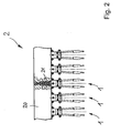
- FIG. 2 shows a first embodiment of a contact lens gripping unit 2 according to the invention.
- Gripping unit 2 comprises a mounting bar 20 to which a plurality of individual contact lens grippers 1 as described above is mounted - in the embodiment shown, five individual grippers 1 are seen mounted to mounting bar 20, but any other number is conceivable.
- a common pressure distribution channel 21 may be provided within mounting bar 20 so that the individual grippers 1 may be pneumatically actuated with only one external pressure supply.
- FIGS. 3-10 one variant of how a contact lens can be removed from a male mold half to which it sticks after opening of the mold will now be described.
- the tips 102 and 112 of sleeves 101 and 111 of gripper arms 10 and 11 have been lowered until they touch portion 30 of male mold half 3 that surrounds the lens-shaping insert 31.
- An additional guiding sleeve 32 is shown in FIG. 3 the purpose of which is not relevant for the understanding of the instant invention.
- the gripper arms are not actuated (i.e. the actuation cylinder 121 - see FIG. 20 - is not expanded).
- the contact lens CL to be grasped is located between the free ends of grippers arms 10 and 11, that is to say between the tips 102 and 112 of sleeves 101 and 111.
- gripper arms 10 and 11 are then actuated so as to move towards each other.
- a situation in which this movement of gripper arms 10 and 11 has just begun is shown in FIG. 4 .
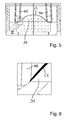
- Gripper arms 10 and 11 are then further moved towards each other until the engage contact lens CL that rests on lens-shaping insert 31. This is shown in FIG. 5 , and in particular detail VI of FIG. 5 is shown enlarged in FIG. 6 .
- tip 112 shown in FIG. 6 engages contact lens CL such that the rear part of the edge of contact lens cannot be damaged, since this rear part of the contact lens edge significantly affects the wearing comfort of contact lens CL.
- the gripper arms 10 and 11 and consequently also tips 112 and 102 of sleeves 111 and 101 are then further moved together and upwards in accordance with the shape of lens-shaping portion 31 so as to grasp contact lens CL and remove it from lens-shaping portion 31.
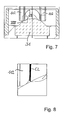
- a further intermediate position of this movement is shown in FIG. 7 , with detail VIII of FIG. 7 being shown enlarged in FIG. 8 .
- Moving gripper arms 10 and 11 (and consequently tips 112 and 102 of sleeves 111 and 101) towards each other and upwards results in that contact lens CL is fully grasped between tips 112 and 102, as this is shown in FIG. 9 , with detail X being shown enlarged in FIG. 10 .
- Contact lens CL has then been fully removed from lens-shaping portion 31 and can be transferred, for example, to an inspection station.
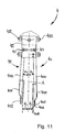
- FIG. 11 a second embodiment of a contact lens gripper in accordance with the invention is shown.
- the gripper 4 comprises a first gripper arm 40 and a second gripper arm 41, which are hingedly connected to an actuation support 42 via a respective hinge 43.
- First gripper arm 40 comprises a rigid carrier arm 400 that is provided in the region of its free end with an elastic sleeve 401.
- Elastic sleeve 401 can be mounted to carrier arm 400 by pushing it over the free end of rigid carrier arm 400.
- tip 402 of elastic sleeve 401 extends beyond the free end of rigid carrier arm 400.
- Second gripper arm 41 comprises a rigid carrier arm 410 that is provided in the region of its free end with an elastic sleeve 411 that has been mounted to carrier arm 410 as has been described above for elastic sleeve 401 and carrier arm 400. Again, when mounted, tip 412 of elastic sleeve 411 extends beyond the free end of rigid carrier arm 410.
- the length of rigid carrier arms 400 and 410 is not equal in the embodiment of the gripper shown in FIG. 11 , while the length of elastic sleeves 401 and 411 is equal.
- the first and second gripper arms 40 and 41 are of different length.
- the shape of sleeve 401 is different from the shape of sleeve 411.
- sleeve 411 is similar to the shape of sleeves 101 and 111 shown in FIG. 1 and in FIG. 21 and FIG. 22 , respectively, sleeve 401 looks different, since it comprises a rounded outwardly facing surface 403 and tapers towards a pointed apex 404.
- Actuation support 42 is constructed similar to actuation support 12 shown in FIG. 1 and FIG. 20 , respectively, that is to say gripper arms 40 and 41 may be pneumatically actuated by a pressure supply and its working principle is similar to that already described above. Therefore, for a detailed description of the working principle of actuation support 42 it is referred to that part of the description where the working principle of actuation support 12 is described in more detail (see above).
- Set screws 422 are provided for individually setting the initial distances d 1 and d 2 between the tip 402 or 412, respectively, and the central axis A of gripper 4, as well the divergence angles ⁇ 1 and ⁇ 2 between gripper arms 40 and 41, respectively, and central axis A.
- the distances d 1 and d 2 as well as the angles ⁇ 1 and ⁇ 2 are different in this embodiment of the gripper 4.
- actuation cylinder is in the relaxed state (i.e. not expanded).
- FIG. 12 shows a first embodiment of a contact lens gripping unit 5 according to the instant invention.
- Gripping unit 5 comprises a mounting bar 50 to which a plurality of individual contact lens grippers 4 as described above is mounted - in the embodiment shown, five individual grippers 4 are seen mounted to mounting bar 50, but any other number is conceivable.
- a common pressure distribution channel 51 may be provided within mounting bar 50 so that the individual grippers 4 may be pneumatically actuated with only one external pressure supply being needed.
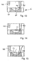
- FIG. 13 the tips 402 and 412 of sleeves 401 and 411 of gripper arms 40 and 41 have been lowered until the apex 404 of tip 402 of sleeve 401 touches contact lens CL that rests in female lens-shaping insert 61 which is surrounded by portion 60 of female mold half 6.
- the gripper arms are not actuated (i.e. the actuation cylinder is not expanded).
- Tip 412 of sleeve 411 of gripper arm 41 is located above female mold half 6.
- FIG. 14 Gripper 4 and is then further lowered and consequently contact lens CL is slightly tilted, as this is shown in FIG. 14 .
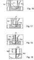
- Further downward movement of gripper 4 results in a slight deformation of tip 402 having the rounded outer surface and in further tilting of contact lens CL, as this is shown in FIG. 15 and in FIG. 16 .
- the tips 402 and 412 are then moved towards each other so that the tilted lens is located between the free ends of gripper arms 40 and 41, that is to say between tips 402 and 412 of sleeves 401 and 411, so that it can be grasped ( FIG. 17 ). Tips 402 and 412 are then further moved towards each other until contact lens CL is safely grasped between tips 402 and 412, as this is shown in FIG. 18 and FIG. 19 , wherein FIG. 19 shows an enlarged view of detail XIX of FIG. 18 .
- Contact lens CL has now been fully removed from female mold half 6, is securely held by gripper 4, and can now be transferred, for example, to an
Landscapes
- Engineering & Computer Science (AREA)
- Health & Medical Sciences (AREA)
- Manufacturing & Machinery (AREA)
- Ophthalmology & Optometry (AREA)
- Mechanical Engineering (AREA)
- Robotics (AREA)
- Eyeglasses (AREA)
- Manipulator (AREA)
- Mounting And Adjusting Of Optical Elements (AREA)
- Joining Of Glass To Other Materials (AREA)
Abstract
Description
- The instant invention deals with a contact lens gripper in accordance with the independent patent claim, as well as with a contact lens gripping unit comprising a plurality of such individual contact lens grippers. The instant invention also deals with a process for grasping a contact lens, using a contact lens gripper.
- During manufacture of soft contact lenses, in particular - but not exclusively - of single wear soft contact lenses, the contact lenses have to be removed from the mold half to which they stick after opening of the respective mold. Although various measures have been suggested in order to make the contact lenses all stick to one dedicated type of mold half (e.g. to make them all stick to the male mold half), a completely reliable measure to achieve this result has hitherto not been found. Accordingly, the situation has to be dealt with that some of the lenses stick to the male mold half while others stick to the female mold half.
- On the other hand, the manufacturing process necessarily must be a highly automated process in order to be able to offer contact lenses at a competitive price. This requires, that in such highly automated process the handling of the contact lens must also be automated, in particular the lenses have to be removed from the respective mold halves to which they stick after they have been molded and after the molds have been opened.
- Since some of the lenses tend to stick to the respective mold half rather strongly, it has been suggested to apply a jet of water to the lenses (or alternatively to apply a puff of steam) as the lenses stick to the mold half so as to loosen them. The thus loosened lenses are then removed by automatic vacuum grippers, such as shown for example in
EP-A-1136241 or inWO-A-03/080320 - While the vacuum grippers hitherto used have been working well, they suffer from the disadvantage that at least some of the water that has been applied to the lenses in order to loosen them from the mold have is sucked into the vacuum pump, so that the vacuum pump must be cleaned from time to time and the manufacturing process must be interrupted. Such an interruption of the manufacturing process in turn affects the overall efficiency of the manufacturing process, let alone that the water sucked in can be detrimental to the vacuum pump. Devices for gripping contact lenses are also disclosed in
US 6,558,584 andUS 4,427,226 . - It is therefore an objective of the invention to suggest a contact lens gripper that overcomes the disadvantages of the prior art contact lens grippers.
- This objective is achieved in accordance with a first aspect of the invention by a contact lens gripper as it is characterised by the features of
independent claim 1. A second aspect of the invention is directed to a contact lens gripping unit comprising a mounting bar to which a plurality of such contact lens grippers are mounted in accordance withclaim 6. A third aspect of the invention deals with a process for grasping a contact lens in accordance with claim 8. Further advantageous aspects are the subject of dependent claims. - In particular, according to a first aspect of the invention, the contact lens gripper comprises a tweezers gripper having first and second gripper arms connected to an actuation support for moving the free ends of the arms towards and away from each other so as to grasp and release the soft contact lens. With the aid of the gripper arms of the tweezers gripper the soft contact lens can be mechanically grasped thus eliminating the disadvantages of vacuum grippers, such as the unintentional sucking in of water into the vacuum pump and the associated need to clean the vacuum pump from time to time.
- In an embodiment of the contact lens tweezers gripper according to the invention, the actuation support comprises set means for individually setting the distance from and the divergence angle to the longitudinal axis of the tweezers gripper for each gripper arm. This is advantageous with respect to the fact, that the gripper can be adjusted to different molds that may be used for contact lens manufacturing.
- In a preferred embodiment of the contact lens tweezers gripper according to the invention, the gripper arms are hingedly connected to the actuation support. This is a technically simple embodiment from a constructional point of view. In addition, as will be explained in more detail, this embodiment allows to actuate the gripper arms in a simple manner.
- According to a further preferred embodiment of the contact lens tweezers gripper according to the invention, the gripper arms are elastic at least in the region of their free ends. In particular, each gripper arm may comprise a rigid carrier arm which is provided at least in the region of its free end with an elastic sleeve, the tip of the respective elastic sleeve extending beyond the free end of its associated rigid carrier arm. The lens is grasped between the tips of the elastic sleeves of the gripper arms. Although the elastic sleeves may deform to a certain extent, they must on the other hand be stiff enough to remove the soft contact lens from the mold half to which it sticks.
- In another preferred embodiment of the contact lens tweezers gripper according to the invention, the length of the rigid carrier arms as well as the length of the sleeves is equal so that as a result the gripper arms are of equal length. This is particularly advantageous when the contact lens is to be removed from a male mold half, as will be explained in further detail below.
- In another preferred embodiment of the contact lens tweezers gripper according to the invention, the length of the rigid carrier arms is different, one of the carrier arms being longer and the other one being shorter, while the length of the sleeves is equal. As a result, the longer carrier arm being provided with its sleeve is longer than the shorter carrier arm being provided with its sleeve. Preferably, the tip of the sleeve of the longer carrier arm tapers towards its apex and has a rounded outwardly facing surface. This embodiment is advantageous when the contact lens is to be removed from a female mold half, as will be explained in further detail below.
- According to a second aspect of the invention, a contact lens gripping unit is suggested comprising a mounting bar to which a plurality of individual contact lens grippers are mounted at a predetermined distance from each other. Each of the individual grippers is a contact lens gripper corresponding to one of the above-described embodiments.
- In an embodiment of such a contact lens gripping unit the individual contact lens grippers of the contact lens gripping unit can be pneumatically actuated through a common pressure distribution channel which is provided in the mounting bar. Accordingly, only one single pressure source is necessary for allowing actuation of all contact lens grippers connected to the mounting bar.
- According to a third aspect of the invention, a process for grasping a contact lens is suggested using a contact lens gripper corresponding to one of the above-described embodiments of the contact lens gripper. The process is suitable especially for removing a soft contact lens from a mold half and comprises the steps of:
- placing the free end of the gripper arms of the contact lens tweezers gripper above the contact lens to be grasped,
- lowering the gripper in a manner such that the contact lens to be grasped is arranged between the free ends of the gripper arms
- actuating the gripper so as to move the gripper arms towards each other in order to grasp the contact lens.
- In one variant of the process according to the invention, the contact lens to be removed rests on a male mold half. A gripper having gripper arms of equal length is used in this variant, and during the step of actuating the gripper so as to move the gripper arms towards each other the gripper is simultaneously moved upwards in accordance with the shape of the male mold half on which the contact lens rests. This allows to reliably remove the contact lens from the male mold half while keeping it grasped between the free ends of the gripper arms.
- In another variant of the process according to the invention, the contact lens to be removed rests on a female mold half. A gripper having gripper arms of different lengths is used in this variant, and during the step of lowering the gripper the (elastic) tip of the longer one of the gripper arms causes the contact lens to tilt to a position in which it is arranged between the free ends of the gripper arms. This allows to reliably remove the contact lens from the female mold half. In order to grasp the lens between the free ends of the gripper arms, the lens must first be tilted to a position in which it is arranged between the free ends of the gripper arms in order to enable grasping of the lens.
- Further advantageous aspects of the invention will become apparent from the following description of preferred embodiments of the contact lens tweezers gripper, of the gripper unit, and of the process for grasping a contact lens, with the aid of the drawings in which:
- FIG. 1
- a first embodiment of a contact lens gripper according to the invention
- FIG. 2
- a first embodiment of a contact lens gripping unit according to the invention, comprising a plurality of contact lens grippers of
FIG. 1 - FIG. 3-5
- the free ends of the elastic sleeves of the gripper arms of the contact lens gripper of
FIG. 1 in sequential positions during the process of grasping a soft contact lens and removing it from a male mold half - FIG. 6
- an enlargement of detail VI of
FIG. 5 - FIG. 7
- a further sequential position of the free ends of the elastic sleeves during the process of grasping the contact lens and removing it from the male mold half
- FIG. 8
- the detail VIII of
FIG. 7 - FIG. 9
- the final sequential position of the free ends of the elastic sleeves with the contact lens being securely grasped between the free ends
- FIG. 10
- the detail X of
FIG. 9 - FIG. 11
- a second embodiment of the contact lens gripper according to the invention
- FIG. 12
- a second embodiment of the contact lens gripping unit according to the invention, comprising a plurality of contact lens grippers of
FIG. 11 - FIG. 13-19
- the free ends of the elastic sleeves of the gripper arms of the contact lens gripper of
FIG. 11 in sequential positions during the process of grasping a soft contact lens and removing it from a female mold half - FIG. 20
- the gripper of
FIG. 1 with some additional details being shown - FIG. 21-22
- the sleeve of the gripper arms of the gripper of
FIG. 1 , in a cross-sectional view and in a view from above, respectively - In
FIG. 1 a first embodiment of a contact lens gripper in accordance with the invention is shown. Thegripper 1 comprises afirst gripper arm 10 and asecond gripper arm 11, which are hingedly connected to anactuation support 12 via arespective hinge 13.First gripper arm 10 comprises arigid carrier arm 100 that is provided in the region of its free end with an elastic sleeve 101 (see alsoFIG. 21 and FIG. 22 ).Elastic sleeve 101 can be mounted tocarrier arm 100 by pushing it over the free end ofrigid carrier arm 100. When mounted,tip 102 ofelastic sleeve 101 extends beyond the free end ofrigid carrier arm 100. Correspondingly,second gripper arm 11 comprises arigid carrier arm 110 that is provided in the region of its free end with anelastic sleeve 111 that has been mounted tocarrier arm 110 as has been described above forelastic sleeve 101 andcarrier arm 100. Again, when mounted,tip 112 ofelastic sleeve 111 extends beyond the free end ofrigid carrier arm 110. The length ofrigid carrier arms elastic sleeves second gripper arms -
Actuation support 12 is constructed such (seeFIG. 20 ), thatgripper arms actuation support 12 is provided with apressure inlet 120 and anactuation cylinder 121 which may be activated by pressure so as to be expanded. Upon expansion,actuation cylinder 121 engagesgripper arms hinge 13 and pushes them outwardly. As a result, the free ends ofgripper arms tips sleeves - Set
screws 122 are provided for individually setting the initial distance d between thetip gripper 1, as well the divergence angle α betweengripper arms α actuation cylinder 121 is in the relaxed state (i.e. not expanded). By setting distance d and angle α gripper 1 can be perfectly adjusted to the dimensions of the mold half from which the contact lens has to be removed. -
FIG. 2 shows a first embodiment of a contactlens gripping unit 2 according to the invention.Gripping unit 2 comprises a mountingbar 20 to which a plurality of individualcontact lens grippers 1 as described above is mounted - in the embodiment shown, fiveindividual grippers 1 are seen mounted to mountingbar 20, but any other number is conceivable. A commonpressure distribution channel 21 may be provided within mountingbar 20 so that theindividual grippers 1 may be pneumatically actuated with only one external pressure supply. - With the aid of
FIGS. 3-10 one variant of how a contact lens can be removed from a male mold half to which it sticks after opening of the mold will now be described. InFIG. 3 thetips sleeves gripper arms portion 30 ofmale mold half 3 that surrounds the lens-shapinginsert 31. An additional guidingsleeve 32 is shown inFIG. 3 the purpose of which is not relevant for the understanding of the instant invention. In the position shown inFIG. 3 , the gripper arms are not actuated (i.e. the actuation cylinder 121 - seeFIG. 20 - is not expanded). The contact lens CL to be grasped is located between the free ends ofgrippers arms tips sleeves - The
gripper arms gripper arms FIG. 4 .Gripper arms insert 31. This is shown inFIG. 5 , and in particular detail VI ofFIG. 5 is shown enlarged inFIG. 6 . It is to be noted, thattip 112 shown inFIG. 6 engages contact lens CL such that the rear part of the edge of contact lens cannot be damaged, since this rear part of the contact lens edge significantly affects the wearing comfort of contact lens CL. - The
gripper arms tips sleeves portion 31 so as to grasp contact lens CL and remove it from lens-shapingportion 31. A further intermediate position of this movement is shown inFIG. 7 , with detail VIII ofFIG. 7 being shown enlarged inFIG. 8 . Movinggripper arms 10 and 11 (and consequentlytips sleeves 111 and 101) towards each other and upwards results in that contact lens CL is fully grasped betweentips FIG. 9 , with detail X being shown enlarged inFIG. 10 . Contact lens CL has then been fully removed from lens-shapingportion 31 and can be transferred, for example, to an inspection station. - In
FIG. 11 a second embodiment of a contact lens gripper in accordance with the invention is shown. Thegripper 4 comprises afirst gripper arm 40 and asecond gripper arm 41, which are hingedly connected to anactuation support 42 via arespective hinge 43.First gripper arm 40 comprises arigid carrier arm 400 that is provided in the region of its free end with anelastic sleeve 401.Elastic sleeve 401 can be mounted tocarrier arm 400 by pushing it over the free end ofrigid carrier arm 400. When mounted,tip 402 ofelastic sleeve 401 extends beyond the free end ofrigid carrier arm 400.Second gripper arm 41 comprises arigid carrier arm 410 that is provided in the region of its free end with anelastic sleeve 411 that has been mounted tocarrier arm 410 as has been described above forelastic sleeve 401 andcarrier arm 400. Again, when mounted,tip 412 ofelastic sleeve 411 extends beyond the free end ofrigid carrier arm 410. However, in contrast to the embodiment of the gripper shown inFIG. 1 the length ofrigid carrier arms FIG. 11 , while the length ofelastic sleeves second gripper arms sleeve 401 is different from the shape ofsleeve 411. Whilesleeve 411 is similar to the shape ofsleeves FIG. 1 and inFIG. 21 and FIG. 22 , respectively,sleeve 401 looks different, since it comprises a rounded outwardly facingsurface 403 and tapers towards apointed apex 404. -
Actuation support 42 is constructed similar toactuation support 12 shown inFIG. 1 andFIG. 20 , respectively, that is to saygripper arms actuation support 42 it is referred to that part of the description where the working principle ofactuation support 12 is described in more detail (see above). - Set
screws 422 are provided for individually setting the initial distances d1 and d2 between thetip gripper 4, as well the divergence angles α1 and α2 betweengripper arms gripper 4. During the setting of the distances d1 and d2 and of angles α1 and α2 actuation cylinder is in the relaxed state (i.e. not expanded). By setting the distances d1 and d2 and the angles α1 and α2 gripper 4 can be perfectly adjusted to the dimensions of the mold half from which the contact lens has to be removed. -
FIG. 12 shows a first embodiment of a contactlens gripping unit 5 according to the instant invention.Gripping unit 5 comprises a mountingbar 50 to which a plurality of individualcontact lens grippers 4 as described above is mounted - in the embodiment shown, fiveindividual grippers 4 are seen mounted to mountingbar 50, but any other number is conceivable. A commonpressure distribution channel 51 may be provided within mountingbar 50 so that theindividual grippers 4 may be pneumatically actuated with only one external pressure supply being needed. - With the aid of
FIGs. 13-19 one variant of how a contact lens can be removed from a female mold half to which it sticks after opening of the mold will now be described. InFIG. 13 thetips sleeves gripper arms tip 402 ofsleeve 401 touches contact lens CL that rests in female lens-shapinginsert 61 which is surrounded byportion 60 offemale mold half 6. In the position shown inFIG. 13 , the gripper arms are not actuated (i.e. the actuation cylinder is not expanded).Tip 412 ofsleeve 411 ofgripper arm 41 is located abovefemale mold half 6.Gripper 4 and is then further lowered and consequently contact lens CL is slightly tilted, as this is shown inFIG. 14 . Further downward movement ofgripper 4 results in a slight deformation oftip 402 having the rounded outer surface and in further tilting of contact lens CL, as this is shown inFIG. 15 and inFIG. 16 . Thetips gripper arms tips sleeves FIG. 17 ).Tips tips FIG. 18 and FIG. 19 , whereinFIG. 19 shows an enlarged view of detail XIX ofFIG. 18 . Contact lens CL has now been fully removed fromfemale mold half 6, is securely held bygripper 4, and can now be transferred, for example, to an inspection station. - It is to be noted, that in a highly automated lens manufacturing process it may be possible, that it cannot be safely predicted, whether a molded soft contact lens sticks to the
male mold half 3 or to thefemale mold half 6. Accordingly, it is advantageous for such manufacturing process to provide grippers for both types of mold halves, for themale mold halves 3 as well as for thefemale mold halves 6, so as to be sure that the lens can be automatically removed from the mold half (e.g. after having been loosened from the respective mold half by means of a water jet).
Claims (10)
- Contact lens gripper characterized in that is comprises a tweezers gripper (1;4) having first (10;40) and second (11;41) gripper arms connected to an actuation support (12;42) for moving the free ends of the arms towards and away from each other so as to grasp and release a soft contact lens (CL), wherein the gripper arms (10,11;40,41) are hingedly (13;43) connected to the actuation support (12;42) and wherein the actuation support (12;42) comprises set means (122;422) for individually setting the distance (d;d1,d2) from and the divergence angle (α;α1,α2) to the longitudinal axis (A) of the tweezers gripper (1;4) for each gripper arm (10,11;40,41).
- Contact lens gripper according to claim 1, wherein the gripper arms (10,11;40,41) are elastic at least in the region of their free ends.
- Contact lens gripper according to claim 2, wherein each gripper arm (10,11;40,41) comprises a rigid carrier arm (100,110;400,410) which is provided at least in the region of its free end with an elastic sleeve (101,111;401,411), the tip (102,112;402,412) of the respective elastic sleeve (101,111;401,411) extending beyond the free end of its associated rigid carrier arm (100,110;400,410).
- Contact lens gripper according to claim 3, wherein the length of the rigid carrier arms (100,110) as well as the length of the sleeves (101,111) is equal so that as a result the gripper arms (100,110) are of equal length.
- Contact lens gripper according to claim 3, wherein the length of the rigid carrier arms (400,410) is different, one of the carrier arms (400) being longer and the other one (410) being shorter, while the length of the sleeves (401,411) is equal, so that as a result the longer carrier arm (400) being provided with its sleeve (401) is longer than the shorter carrier arm (410) being provided with its sleeve (411), and wherein the tip (402) of the sleeve (401) of the longer arm tapers towards its apex (404) and has a rounded outwardly facing surface (403).
- Contact lens gripping unit (2;5) comprising a mounting bar (20;50) to which a plurality of individual contact lens grippers are mounted at a predetermined distance from each other, wherein each of the individual grippers is a contact lens gripper (1 ;4) according to any one of the preceding claims.
- Contact lens gripping unit according to claim 6, wherein the individual contact lens grippers (1;4) of the contact lens gripping unit can be pneumatically actuated through a common pressure distribution channel (21;51) which is provided in the mounting bar (20;50).
- Process for grasping a contact lens using a contact lens gripper (1;4) according to any one of claims 1 to 5, especially for removing a soft contact lens (CL) from a mold half (3;6), the process comprising the steps of:- placing the free end of the gripper arms (10,11;40,41) of the contact lens tweezers gripper (1;4) above the contact lens (CL) to be grasped,- lowering the gripper (1;4) in a manner such that the contact lens (CL) to be grasped is arranged between the free ends of the gripper arms (10,11;40,41)- actuating the gripper (1;4) so as to move the gripper arms (10,11;40,41) towards each other in order to grasp the contact lens (CL).
- Process according to claim 8, wherein the contact lens to be removed rests on a male mold half (3), and wherein a gripper (1) having gripper arms (10,11) of equal length is used, in which process during the step of actuating the gripper (1) so as to move the gripper arms (10,11) towards each other the gripper (1) is simultaneously moved upwards in accordance with the shape of the male mold half (3) on which the contact lens (CL) rests.
- Process according to claim 8, wherein the contact lens (CL) to be removed rests on a female mold half (6), and wherein a gripper (4) having gripper arms (40,41) of different lengths is used, in which process during the step of lowering the gripper (4) the tip of the longer one of the gripper arms (40) causes the contact lens (CL) to tilt to a position in which it is arranged between the free ends of the gripper arms (40,41).
Priority Applications (1)
| Application Number | Priority Date | Filing Date | Title |
|---|---|---|---|
| EP06724794A EP1883527B1 (en) | 2005-05-13 | 2006-05-11 | Gripper for moving and positioning contact lenses |
Applications Claiming Priority (3)
| Application Number | Priority Date | Filing Date | Title |
|---|---|---|---|
| EP05010469 | 2005-05-13 | ||
| EP06724794A EP1883527B1 (en) | 2005-05-13 | 2006-05-11 | Gripper for moving and positioning contact lenses |
| PCT/EP2006/004432 WO2006119993A1 (en) | 2005-05-13 | 2006-05-11 | Gripper for moving and positioning contact lenses |
Publications (2)
| Publication Number | Publication Date |
|---|---|
| EP1883527A1 EP1883527A1 (en) | 2008-02-06 |
| EP1883527B1 true EP1883527B1 (en) | 2009-09-16 |
Family
ID=35427585
Family Applications (1)
| Application Number | Title | Priority Date | Filing Date |
|---|---|---|---|
| EP06724794A Expired - Lifetime EP1883527B1 (en) | 2005-05-13 | 2006-05-11 | Gripper for moving and positioning contact lenses |
Country Status (7)
| Country | Link |
|---|---|
| US (1) | US7887111B2 (en) |
| EP (1) | EP1883527B1 (en) |
| CN (1) | CN101208192B (en) |
| AT (1) | ATE442952T1 (en) |
| DE (1) | DE602006009251D1 (en) |
| MY (1) | MY140797A (en) |
| WO (1) | WO2006119993A1 (en) |
Families Citing this family (10)
| Publication number | Priority date | Publication date | Assignee | Title |
|---|---|---|---|---|
| WO2007034176A2 (en) * | 2005-03-18 | 2007-03-29 | Pvaxx Research And Development Limited | Unloading apparatus for rotationnaly moulded articles, and unloading method related thereto |
| GB2425506B (en) | 2005-04-26 | 2010-11-10 | Pvaxx Res & Dev Ltd | Load carrying apparatus and method of manufacture |
| US20100129181A1 (en) * | 2008-11-21 | 2010-05-27 | Blasiak Joseph D | Lens handler |
| US8464412B2 (en) * | 2010-01-19 | 2013-06-18 | Cheng Uei Precision Industry Co., Ltd. | Clutching jig |
| WO2012066060A1 (en) | 2010-11-19 | 2012-05-24 | Novartis Ag | Gripper for grasping an ophthalmic lens immersed in a liquid |
| JP2012236265A (en) * | 2011-05-13 | 2012-12-06 | Seiko Epson Corp | Robot hand, and robot |
| CN107014593A (en) * | 2017-05-11 | 2017-08-04 | 合肥锐光科学仪器有限公司 | A kind of contact lenses detection fixture |
| WO2021144738A1 (en) | 2020-01-16 | 2021-07-22 | Alcon Inc. | Cleaner for cleaning grippers for ophthalmic lenses |
| CN112433393A (en) * | 2020-10-22 | 2021-03-02 | 四川大学华西医院 | Ultrasonic cleaning device for contact lenses |
| WO2025073114A1 (en) * | 2023-10-07 | 2025-04-10 | 深圳市逸文科技有限公司 | Ar glasses, assembling method for ar glasses, and clamp device |
Family Cites Families (13)
| Publication number | Priority date | Publication date | Assignee | Title |
|---|---|---|---|---|
| US4093291A (en) * | 1977-08-17 | 1978-06-06 | Schurgin Herbert L | Contact lens application and removal instrument |
| US4427226A (en) * | 1982-04-22 | 1984-01-24 | Shartzer Ewart E | Plastic lens insertion and removal device |
| FR2589770B1 (en) * | 1985-11-07 | 1988-03-11 | Normandie Ste Indle Basse | IMPROVED CLAMP OR ROBOT HANDLE DEVICE. |
| DE3676195D1 (en) * | 1986-04-28 | 1991-01-24 | Ibm | ROBOT ASSEMBLY DEVICE WITH A ROBOT TOOL FOR PLACING SEVERAL COMPONENTS ON A WORKPIECE. |
| US4750771A (en) * | 1987-02-19 | 1988-06-14 | Emmett Bradley K | Lens cleaning and handling device |
| US4950011A (en) * | 1988-10-24 | 1990-08-21 | Nicky Borcea | Tool for precisely positioning a workpiece |
| US5895192C1 (en) * | 1994-06-10 | 2001-11-06 | Johnson & Johnson Vision Prod | Apparatus and method for removing and transporting articles from molds |
| US6869549B2 (en) * | 1999-05-05 | 2005-03-22 | Johnson & Johnson Vision Care, Inc. | Method and mold for making ophthalmic devices |
| JP4634629B2 (en) | 2000-03-16 | 2011-02-16 | ノバルティス アーゲー | Contact lens removal device |
| US6558584B1 (en) * | 2000-03-31 | 2003-05-06 | Bausch & Lomb Incorporated | Apparatus and method for handling an ophthalmic lens |
| GB2360730B (en) * | 2000-03-31 | 2004-09-22 | Bausch & Lomb Uk Ltd | Apparatus and method for separating contact lens molds |
| US6994386B2 (en) | 2002-03-21 | 2006-02-07 | Novartis Ag | Gripper |
| US6916055B2 (en) * | 2002-10-24 | 2005-07-12 | Finisar Corporation | Lens press tool |
-
2006
- 2006-05-09 MY MYPI20062125A patent/MY140797A/en unknown
- 2006-05-11 CN CN2006800165173A patent/CN101208192B/en not_active Expired - Fee Related
- 2006-05-11 WO PCT/EP2006/004432 patent/WO2006119993A1/en not_active Ceased
- 2006-05-11 EP EP06724794A patent/EP1883527B1/en not_active Expired - Lifetime
- 2006-05-11 DE DE602006009251T patent/DE602006009251D1/en not_active Expired - Lifetime
- 2006-05-11 AT AT06724794T patent/ATE442952T1/en not_active IP Right Cessation
-
2007
- 2007-11-13 US US11/983,883 patent/US7887111B2/en active Active
Also Published As
| Publication number | Publication date |
|---|---|
| US20080084080A1 (en) | 2008-04-10 |
| DE602006009251D1 (en) | 2009-10-29 |
| EP1883527A1 (en) | 2008-02-06 |
| CN101208192B (en) | 2010-05-19 |
| WO2006119993A1 (en) | 2006-11-16 |
| ATE442952T1 (en) | 2009-10-15 |
| CN101208192A (en) | 2008-06-25 |
| MY140797A (en) | 2010-01-15 |
| US7887111B2 (en) | 2011-02-15 |
Similar Documents
| Publication | Publication Date | Title |
|---|---|---|
| US7887111B2 (en) | Gripper for moving and positioning contact lenses | |
| JP4888811B2 (en) | Taking out an ophthalmic lens using gas | |
| EP3421192B1 (en) | Gripping device, robot having such a gripping device, and wire electric discharge machining machine cell, having such a robot | |
| AU2016303433B2 (en) | Seed sampling system and method | |
| FR3066422A1 (en) | MANIPULATOR PREHENSER WITH GRIPPING ARMS COMPRISING BRANCHES CONNECTED WITH STATE CHANGING ARTICLES. | |
| JP2009083037A (en) | Gripping tool | |
| EP3468332A1 (en) | Electronic component inserting device | |
| BR0000694B1 (en) | method and apparatus for transferring a contact lens. | |
| EP3694690A1 (en) | End of arm tools for soft robotic systems | |
| JP2018523522A (en) | Acetabular cup extractor | |
| US11654594B2 (en) | Method and system for demolding a flexible mold of dried wet-cast concrete products | |
| AU2021203145B2 (en) | System for loading a dishwasher, gripper system for a loading arrangement for loading a dishwasher, and also dishwasher | |
| JP6310611B2 (en) | Gripper assembly and method for gripping tire components | |
| DK179774B9 (en) | Tool and apparatus for gutting fish by means of suction and scraping elements | |
| JP7399937B2 (en) | Removal trough for wire processing system, wire processing system, and method for removing one or more wires from the removal trough | |
| EP2183079A1 (en) | Vacuum gripper with a plurality of longitudinal isolating elements | |
| KR102689219B1 (en) | Soft gripper | |
| JPH08132378A (en) | Holding device hand and holding device | |
| JP2007185773A (en) | Blade changing method for circular shear slitter, robot hand used in the method, and handling robot including the robot hand | |
| EP2199840A1 (en) | Arrangement for processing optical waveguides | |
| JPH08132381A (en) | Holding device hand and holding device | |
| KR200264125Y1 (en) | An exclusion instrument of guinea pepper stem | |
| TWI394651B (en) | Apparatus and method for evaluating alignment of a robotic end tool and a molding apparatus | |
| JPS60229716A (en) | Takeout device of cylindrical rubber product | |
| CA2992658C (en) | Seed sampling system and method |
Legal Events
| Date | Code | Title | Description |
|---|---|---|---|
| PUAI | Public reference made under article 153(3) epc to a published international application that has entered the european phase |
Free format text: ORIGINAL CODE: 0009012 |
|
| 17P | Request for examination filed |
Effective date: 20071206 |
|
| AK | Designated contracting states |
Kind code of ref document: A1 Designated state(s): AT BE BG CH CY CZ DE DK EE ES FI FR GB GR HU IE IS IT LI LT LU LV MC NL PL PT RO SE SI SK TR |
|
| DAX | Request for extension of the european patent (deleted) | ||
| RAP1 | Party data changed (applicant data changed or rights of an application transferred) |
Owner name: NOVARTIS AG |
|
| GRAP | Despatch of communication of intention to grant a patent |
Free format text: ORIGINAL CODE: EPIDOSNIGR1 |
|
| GRAS | Grant fee paid |
Free format text: ORIGINAL CODE: EPIDOSNIGR3 |
|
| GRAA | (expected) grant |
Free format text: ORIGINAL CODE: 0009210 |
|
| AK | Designated contracting states |
Kind code of ref document: B1 Designated state(s): AT BE BG CH CY CZ DE DK EE ES FI FR GB GR HU IE IS IT LI LT LU LV MC NL PL PT RO SE SI SK TR |
|
| REG | Reference to a national code |
Ref country code: GB Ref legal event code: FG4D |
|
| REG | Reference to a national code |
Ref country code: CH Ref legal event code: EP |
|
| REG | Reference to a national code |
Ref country code: IE Ref legal event code: FG4D |
|
| REF | Corresponds to: |
Ref document number: 602006009251 Country of ref document: DE Date of ref document: 20091029 Kind code of ref document: P |
|
| PG25 | Lapsed in a contracting state [announced via postgrant information from national office to epo] |
Ref country code: SE Free format text: LAPSE BECAUSE OF FAILURE TO SUBMIT A TRANSLATION OF THE DESCRIPTION OR TO PAY THE FEE WITHIN THE PRESCRIBED TIME-LIMIT Effective date: 20090916 Ref country code: LT Free format text: LAPSE BECAUSE OF FAILURE TO SUBMIT A TRANSLATION OF THE DESCRIPTION OR TO PAY THE FEE WITHIN THE PRESCRIBED TIME-LIMIT Effective date: 20090916 Ref country code: FI Free format text: LAPSE BECAUSE OF FAILURE TO SUBMIT A TRANSLATION OF THE DESCRIPTION OR TO PAY THE FEE WITHIN THE PRESCRIBED TIME-LIMIT Effective date: 20090916 |
|
| LTIE | Lt: invalidation of european patent or patent extension |
Effective date: 20090916 |
|
| PG25 | Lapsed in a contracting state [announced via postgrant information from national office to epo] |
Ref country code: NL Free format text: LAPSE BECAUSE OF FAILURE TO SUBMIT A TRANSLATION OF THE DESCRIPTION OR TO PAY THE FEE WITHIN THE PRESCRIBED TIME-LIMIT Effective date: 20090916 Ref country code: SI Free format text: LAPSE BECAUSE OF FAILURE TO SUBMIT A TRANSLATION OF THE DESCRIPTION OR TO PAY THE FEE WITHIN THE PRESCRIBED TIME-LIMIT Effective date: 20090916 Ref country code: LV Free format text: LAPSE BECAUSE OF FAILURE TO SUBMIT A TRANSLATION OF THE DESCRIPTION OR TO PAY THE FEE WITHIN THE PRESCRIBED TIME-LIMIT Effective date: 20090916 Ref country code: PL Free format text: LAPSE BECAUSE OF FAILURE TO SUBMIT A TRANSLATION OF THE DESCRIPTION OR TO PAY THE FEE WITHIN THE PRESCRIBED TIME-LIMIT Effective date: 20090916 |
|
| NLV1 | Nl: lapsed or annulled due to failure to fulfill the requirements of art. 29p and 29m of the patents act | ||
| PG25 | Lapsed in a contracting state [announced via postgrant information from national office to epo] |
Ref country code: CY Free format text: LAPSE BECAUSE OF FAILURE TO SUBMIT A TRANSLATION OF THE DESCRIPTION OR TO PAY THE FEE WITHIN THE PRESCRIBED TIME-LIMIT Effective date: 20090916 |
|
| PG25 | Lapsed in a contracting state [announced via postgrant information from national office to epo] |
Ref country code: IS Free format text: LAPSE BECAUSE OF FAILURE TO SUBMIT A TRANSLATION OF THE DESCRIPTION OR TO PAY THE FEE WITHIN THE PRESCRIBED TIME-LIMIT Effective date: 20100116 Ref country code: EE Free format text: LAPSE BECAUSE OF FAILURE TO SUBMIT A TRANSLATION OF THE DESCRIPTION OR TO PAY THE FEE WITHIN THE PRESCRIBED TIME-LIMIT Effective date: 20090916 Ref country code: ES Free format text: LAPSE BECAUSE OF FAILURE TO SUBMIT A TRANSLATION OF THE DESCRIPTION OR TO PAY THE FEE WITHIN THE PRESCRIBED TIME-LIMIT Effective date: 20091227 Ref country code: CZ Free format text: LAPSE BECAUSE OF FAILURE TO SUBMIT A TRANSLATION OF THE DESCRIPTION OR TO PAY THE FEE WITHIN THE PRESCRIBED TIME-LIMIT Effective date: 20090916 Ref country code: RO Free format text: LAPSE BECAUSE OF FAILURE TO SUBMIT A TRANSLATION OF THE DESCRIPTION OR TO PAY THE FEE WITHIN THE PRESCRIBED TIME-LIMIT Effective date: 20090916 Ref country code: PT Free format text: LAPSE BECAUSE OF FAILURE TO SUBMIT A TRANSLATION OF THE DESCRIPTION OR TO PAY THE FEE WITHIN THE PRESCRIBED TIME-LIMIT Effective date: 20100118 |
|
| PG25 | Lapsed in a contracting state [announced via postgrant information from national office to epo] |
Ref country code: SK Free format text: LAPSE BECAUSE OF FAILURE TO SUBMIT A TRANSLATION OF THE DESCRIPTION OR TO PAY THE FEE WITHIN THE PRESCRIBED TIME-LIMIT Effective date: 20090916 |
|
| PG25 | Lapsed in a contracting state [announced via postgrant information from national office to epo] |
Ref country code: AT Free format text: LAPSE BECAUSE OF FAILURE TO SUBMIT A TRANSLATION OF THE DESCRIPTION OR TO PAY THE FEE WITHIN THE PRESCRIBED TIME-LIMIT Effective date: 20090916 Ref country code: BE Free format text: LAPSE BECAUSE OF FAILURE TO SUBMIT A TRANSLATION OF THE DESCRIPTION OR TO PAY THE FEE WITHIN THE PRESCRIBED TIME-LIMIT Effective date: 20090916 |
|
| PLBE | No opposition filed within time limit |
Free format text: ORIGINAL CODE: 0009261 |
|
| STAA | Information on the status of an ep patent application or granted ep patent |
Free format text: STATUS: NO OPPOSITION FILED WITHIN TIME LIMIT |
|
| PG25 | Lapsed in a contracting state [announced via postgrant information from national office to epo] |
Ref country code: DK Free format text: LAPSE BECAUSE OF FAILURE TO SUBMIT A TRANSLATION OF THE DESCRIPTION OR TO PAY THE FEE WITHIN THE PRESCRIBED TIME-LIMIT Effective date: 20090916 |
|
| 26N | No opposition filed |
Effective date: 20100617 |
|
| PG25 | Lapsed in a contracting state [announced via postgrant information from national office to epo] |
Ref country code: GR Free format text: LAPSE BECAUSE OF FAILURE TO SUBMIT A TRANSLATION OF THE DESCRIPTION OR TO PAY THE FEE WITHIN THE PRESCRIBED TIME-LIMIT Effective date: 20091217 |
|
| PG25 | Lapsed in a contracting state [announced via postgrant information from national office to epo] |
Ref country code: MC Free format text: LAPSE BECAUSE OF NON-PAYMENT OF DUE FEES Effective date: 20100531 |
|
| REG | Reference to a national code |
Ref country code: CH Ref legal event code: PL |
|
| REG | Reference to a national code |
Ref country code: FR Ref legal event code: ST Effective date: 20110131 |
|
| PG25 | Lapsed in a contracting state [announced via postgrant information from national office to epo] |
Ref country code: CH Free format text: LAPSE BECAUSE OF NON-PAYMENT OF DUE FEES Effective date: 20100531 Ref country code: LI Free format text: LAPSE BECAUSE OF NON-PAYMENT OF DUE FEES Effective date: 20100531 |
|
| PG25 | Lapsed in a contracting state [announced via postgrant information from national office to epo] |
Ref country code: IT Free format text: LAPSE BECAUSE OF FAILURE TO SUBMIT A TRANSLATION OF THE DESCRIPTION OR TO PAY THE FEE WITHIN THE PRESCRIBED TIME-LIMIT Effective date: 20090916 |
|
| PG25 | Lapsed in a contracting state [announced via postgrant information from national office to epo] |
Ref country code: FR Free format text: LAPSE BECAUSE OF NON-PAYMENT OF DUE FEES Effective date: 20100531 |
|
| PG25 | Lapsed in a contracting state [announced via postgrant information from national office to epo] |
Ref country code: LU Free format text: LAPSE BECAUSE OF NON-PAYMENT OF DUE FEES Effective date: 20100511 Ref country code: HU Free format text: LAPSE BECAUSE OF FAILURE TO SUBMIT A TRANSLATION OF THE DESCRIPTION OR TO PAY THE FEE WITHIN THE PRESCRIBED TIME-LIMIT Effective date: 20100317 Ref country code: BG Free format text: LAPSE BECAUSE OF FAILURE TO SUBMIT A TRANSLATION OF THE DESCRIPTION OR TO PAY THE FEE WITHIN THE PRESCRIBED TIME-LIMIT Effective date: 20090916 |
|
| PG25 | Lapsed in a contracting state [announced via postgrant information from national office to epo] |
Ref country code: TR Free format text: LAPSE BECAUSE OF FAILURE TO SUBMIT A TRANSLATION OF THE DESCRIPTION OR TO PAY THE FEE WITHIN THE PRESCRIBED TIME-LIMIT Effective date: 20090916 |
|
| PGFP | Annual fee paid to national office [announced via postgrant information from national office to epo] |
Ref country code: GB Payment date: 20140507 Year of fee payment: 9 |
|
| PGFP | Annual fee paid to national office [announced via postgrant information from national office to epo] |
Ref country code: DE Payment date: 20140507 Year of fee payment: 9 |
|
| REG | Reference to a national code |
Ref country code: DE Ref legal event code: R119 Ref document number: 602006009251 Country of ref document: DE |
|
| GBPC | Gb: european patent ceased through non-payment of renewal fee |
Effective date: 20150511 |
|
| PG25 | Lapsed in a contracting state [announced via postgrant information from national office to epo] |
Ref country code: DE Free format text: LAPSE BECAUSE OF NON-PAYMENT OF DUE FEES Effective date: 20151201 Ref country code: GB Free format text: LAPSE BECAUSE OF NON-PAYMENT OF DUE FEES Effective date: 20150511 |
|
| PGFP | Annual fee paid to national office [announced via postgrant information from national office to epo] |
Ref country code: IE Payment date: 20170510 Year of fee payment: 12 |
|
| REG | Reference to a national code |
Ref country code: IE Ref legal event code: MM4A |
|
| PG25 | Lapsed in a contracting state [announced via postgrant information from national office to epo] |
Ref country code: IE Free format text: LAPSE BECAUSE OF NON-PAYMENT OF DUE FEES Effective date: 20180511 |