EP1136241A2 - Apparatus for the removal of contact lenses - Google Patents
Apparatus for the removal of contact lenses Download PDFInfo
- Publication number
- EP1136241A2 EP1136241A2 EP01106262A EP01106262A EP1136241A2 EP 1136241 A2 EP1136241 A2 EP 1136241A2 EP 01106262 A EP01106262 A EP 01106262A EP 01106262 A EP01106262 A EP 01106262A EP 1136241 A2 EP1136241 A2 EP 1136241A2
- Authority
- EP
- European Patent Office
- Prior art keywords
- gripper
- mould half
- contact lens
- spacer
- mould
- Prior art date
- Legal status (The legal status is an assumption and is not a legal conclusion. Google has not performed a legal analysis and makes no representation as to the accuracy of the status listed.)
- Granted
Links
- 125000006850 spacer group Chemical group 0.000 claims abstract description 28
- 230000004907 flux Effects 0.000 abstract description 3
- 238000004519 manufacturing process Methods 0.000 description 6
- 238000000034 method Methods 0.000 description 6
- 239000007858 starting material Substances 0.000 description 3
- 238000001035 drying Methods 0.000 description 2
- 230000000694 effects Effects 0.000 description 2
- 230000006835 compression Effects 0.000 description 1
- 238000007906 compression Methods 0.000 description 1
- 238000004132 cross linking Methods 0.000 description 1
- 230000003247 decreasing effect Effects 0.000 description 1
- 230000001419 dependent effect Effects 0.000 description 1
- 239000012530 fluid Substances 0.000 description 1
- 238000009516 primary packaging Methods 0.000 description 1
- 230000005855 radiation Effects 0.000 description 1
- 239000007787 solid Substances 0.000 description 1
- 238000004659 sterilization and disinfection Methods 0.000 description 1
- 230000003797 telogen phase Effects 0.000 description 1
- XLYOFNOQVPJJNP-UHFFFAOYSA-N water Substances O XLYOFNOQVPJJNP-UHFFFAOYSA-N 0.000 description 1
Images



Classifications
-
- B—PERFORMING OPERATIONS; TRANSPORTING
- B29—WORKING OF PLASTICS; WORKING OF SUBSTANCES IN A PLASTIC STATE IN GENERAL
- B29D—PRODUCING PARTICULAR ARTICLES FROM PLASTICS OR FROM SUBSTANCES IN A PLASTIC STATE
- B29D11/00—Producing optical elements, e.g. lenses or prisms
- B29D11/00009—Production of simple or compound lenses
- B29D11/00038—Production of contact lenses
- B29D11/00125—Auxiliary operations, e.g. removing oxygen from the mould, conveying moulds from a storage to the production line in an inert atmosphere
- B29D11/0023—Transferring contact lenses
- B29D11/0024—Transferring contact lenses using a vacuum suction gripper
-
- B—PERFORMING OPERATIONS; TRANSPORTING
- B29—WORKING OF PLASTICS; WORKING OF SUBSTANCES IN A PLASTIC STATE IN GENERAL
- B29C—SHAPING OR JOINING OF PLASTICS; SHAPING OF MATERIAL IN A PLASTIC STATE, NOT OTHERWISE PROVIDED FOR; AFTER-TREATMENT OF THE SHAPED PRODUCTS, e.g. REPAIRING
- B29C37/00—Component parts, details, accessories or auxiliary operations, not covered by group B29C33/00 or B29C35/00
- B29C37/0003—Discharging moulded articles from the mould
- B29C37/0007—Discharging moulded articles from the mould using means operable from outside the mould for moving between mould parts, e.g. robots
-
- B—PERFORMING OPERATIONS; TRANSPORTING
- B29—WORKING OF PLASTICS; WORKING OF SUBSTANCES IN A PLASTIC STATE IN GENERAL
- B29L—INDEXING SCHEME ASSOCIATED WITH SUBCLASS B29C, RELATING TO PARTICULAR ARTICLES
- B29L2011/00—Optical elements, e.g. lenses, prisms
- B29L2011/0016—Lenses
- B29L2011/0041—Contact lenses
Definitions
- the invention relates to an apparatus for removing contact lenses, especially from a mould half.
- contact lenses particularly disposable lenses that are manufactured in large unit numbers
- contact lenses which are to be manufactured economically in large unit numbers
- mould or full-mould process are preferably manufactured by the so-called mould or full-mould process.
- the lenses are manufactured into their final shape between two mould halves, so that there is no need to subsequently finish the surfaces of the lenses, nor to finish the edges.
- Mould processes are described for example in PCT patent application no. WO/87/04390 or in EP-A 0 367.513.
- the contact lenses produced in this manner are moulded parts having little mechanical stability and a water content of more than 60 % by weight. After manufacture, the lens is metrologically checked, then packaged and subjected to heat sterilisation at 121°C in an autoclave.
- the geometry of the contact lens to be manufactured is defined by the mould cavity.
- the edge of the contact lens is likewise formed by the mould which normally consists of two mould halves.
- the geometry of the edge is defined by the contour of the two mould halves in the area in which they make contact.
- a contact lens To manufacture a contact lens, first of all a certain amount of the fluid starting material is placed in the female mould half. Afterwards, the mould is closed by placing the male mould half thereon. Normally, a surplus of starting material is used, so that, when the mould is closed, the excess is expelled into an overflow area adjacent to the outer mould cavity. The subsequent polymerisation or crosslinking of the starting material takes place by radiation with UV light, or by heat action, or by another non-thermal method.
- the contact lenses thus produced must be removed from the mould halves, preferably from the female mould halves.
- a gripper is provided for example. This is moved in the direction of the mould half and removes the lenses from the mould half by applying suction to the lenses with a vacuum. After removing the lenses, the gripper arm moves into another position, so that further procedures can be carried out, such as drying of the contact lenses on the gripper, checking of the contact lens using an image-processing system, placing the contact lenses in a package, and rinsing and drying of the gripper itself.
- the gripper may be, for example, star-shaped, and in this configuration represents the connecting link between manufacturing the contact lenses and primary packaging. Only the lenses that are centred by the gripper and grasped smoothly can be checked by the image-processing system and subsequently deposited in the package. Thus, the accurate removal of lenses by the gripper is an essential prerequisite to attaining a high yield of the apparatus.
- the contact lenses are first of all loosened and, if desired, also inverted from the male to the female mould half, since the actual removal of the contact lenses is preferably effected from the female mould half.
- several mould halves preferably a figure of 10, can be held in one tool and grasped together by one gripper arm, which accordingly has 10 grippers.
- the gripper arm moves downwards.
- the contact lens is suctioned onto the gripper by a vacuum.
- a vacuum of ca. -0.3 bars (measured on the gripper) is required.
- the distance d between a gripper and a mould half which is measured between the contour edge of a mould half and the end face of the gripper, should be preferably more than 0.5 mm, since otherwise damage may occur on the gripper or on the mould half.
- the gripper is aligned by moving towards the stop of the contour edge of the mould half, then elevated by a specific amount and subsequently fixed. However, this is extremely complex and relatively prone to errors.
- the invention is based on the problem of increasing the distance between the gripper and the mould half whilst maintaining the gripping power, so as to avoid damage to the contact lenses and the mould half, and of enabling the gripper to be simply aligned in relation to the mould half.
- servicing of the apparatus should be simplified.
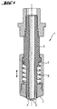
- a gripper 1 illustrated in fig. 1 consists of an outer gripping sleeve 2 and an inner section 3 of the gripper. It is preferably designed so that the inner section 3 is held rigidly and the outer gripping sleeve 2 is movable. However, the reverse may also be the case, in which the inner section 3 is of movable design and the sleeve 2 is held rigidly. Furthermore, it is also possible for the gripping sleeve 2 and the inner section 3 to be formed in one piece, whereby there is no movement of the sleeve 2 and inner section 3 relatively to each other.
- the inner section 3 has a convex end 4, which is equipped with bores 5 that are preferably ring-shaped in order to suck up the contact lens 6.
- the curved end face 7 of the sleeve 2 is connected to this end region 4 of the inner section 3 of the gripper, the curve of this end face 7 being preferably concave.
- a compression spring 8 may be provided to support the inner section 3 or the gripping sleeve 2.
- the inner section 3 of the gripper is connected to a vacuum system which is not illustrated in detail here, and can be pressurised with a vacuum.
- the gripper 1 is positioned above a female mould half 9 in the gripping position. If a movable sleeve 2 is provided, by moving the gripping sleeve 2 upwards, it is ensured that the sleeve 2 does not touch the contour edge 10 of the mould half 9, which could lead to damage.
- the gripper 1 remains in this position first of all for approximately one second. During this time, the contact lens 6 should "float" in the female mould half 9, i.e. become correctly centred. On the other hand, vibration on the gripper 1 should die down. This ensures that the contact lens 6 is received by the gripper 1 in a central position. After this rest phase, the vacuum is applied. The gripper 1 stays in the gripping position for another ca.
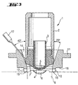
- a spacer 11 is provided between the mould half 9 and the end region 4, 7 of the inner section 3 of the gripper. With this, the distance d between the mould half 9 and the gripper 1 is increased. The distance d between the gripper 1 and the mould half 9 is measured between the contour edge 10 of the mould half 9 and the end face 7 of the gripper 1.
- the spacer 11 is shaped so that it seals the inner section 3 of the gripper in the gripping position towards the exterior. A stop is preferably provided for this, defining the end position for suction of the contact lens. The gripper 1 is moved against it.
- the spacer 11 is advantageously a ring shape.
- the inner area of the spacer 11 may be a conical shape, as illustrated in fig. 3.
- the height tolerance of the gripper 1 lies in the range 200 - 300 ⁇ m.
- this tolerance can be easily balanced by shifting the outer sleeve 2.
- the spacer 11 is provided according to the invention with cut-outs 12.
- the spacer 11 may be formed in one piece or in many parts.
- the cut-outs 12 may be formed as bores, but slits or other geometric shapes are also possible. If pressure is applied by vacuum to the gripper 1, the effect of the vacuum increases through the spacer ring 11, since a defined amount of pressure is exerted on the contact lens.
- the end region 4 of the inner section 3 of the gripper pulls the contact lens 6 and the contact lens 6 then lies centrally around the end region 4 of the gripper 1.
- a distance d of 0.5 mm to 1.5 mm, preferably 1 mm, is provided between the contour edge 10 of the mould half 9 and the end region 4 of the gripper 1. This ensures that the gripper 1 no longer touches the mould half 9 and the contact lens 6 and damage is thus avoided.
- the spacer 11 is formed as a plate 13 which is equipped with conical bores 14.
- the bores 14 may have studs 15 which serve as a buffer surface on the tool holder and at the same time give a certain distance.
- the spaces between the studs represent the cut-outs 12 of the spacer 11. Because of these studs 15, the end face 16 of the plate 13 hovers ca. 1 mm, corresponding to the height of the studs, above the mould halves 9, thereby minimising the danger of damage.
- the gripper moves into the conical rings 14.
- the gripper 1 is designed in particular with a rigid inner section 3 and a movable sleeve 2, high tolerances are cushioned by the sleeve 2 sliding back.
- the gripper is in the gripping position. Air is drawn through the gap 12 between the studs 15 when the vacuum is applied, and the contact lens 6 is sucked up. After removing the lenses 6, the gripper 1 is raised again and the plate 13 is subsequently moved again into its starting position.
- a nozzle 17 may be integrated into the spacer 11 in order to moisten the contact lens prior to removal, thus facilitating removal of the contact lens.
- a further embodiment of a spacer 11 is illustrated in fig. 6. Again, the inner area of the spacer 11 is conical, but in the outer area it has an annular lug 18 with a slot 19 for receiving an elastic O-ring 20.
- the spacers 11 are in turn stored in a support plate 13, which is equipped with slots 21 to receive the lugs 18.
- the O-ring rests directly on the base 22 of the slot 21, thereby providing elastic support of the spacer 11.
- the gripper 1 enters the spacer 11 it is possible to balance the manufacturing tolerances.
- the plate 13 does not rest on the tool holder by means of studs, but is placed directly on stop faces not illustrated here, which are attached to the tool holder and are spaced from the contour edge of the mould half.
- the cut-outs 12 are formed as ring slots 23.
- This embodiment in particular enables a simpler assembly of the spacers 11 to take place in the plate 13, since manufacturing tolerances are balanced by the elastic support means.
- the invention offers the possibility of increasing the gap between the mould half and the gripper without decreasing the gripping strength. In this way, damage to the mould half or the contact lens is avoided, and alignment of the gripper to the mould half is simplified. Moreover, the invention enables flaws in the periphery of the contact lens to be noticed more easily, since owing to the greater flux acting on the contact lens, the latter undergoes greater expansion in the end region of the gripper, thereby enabling possible flaws to be discerned more easily. This can be further enhanced by a conical shape at the end face of the gripper. In addition, the contact lens is centred more accurately on the gripper, whereby image processing is likewise improved.
Landscapes
- Engineering & Computer Science (AREA)
- Robotics (AREA)
- Health & Medical Sciences (AREA)
- Manufacturing & Machinery (AREA)
- Ophthalmology & Optometry (AREA)
- Mechanical Engineering (AREA)
- Eyeglasses (AREA)
Abstract
Description
- Fig. 1
- shows a sectional view of a gripper;
- Fig. 2
- shows a schematic illustration of an embodiment of a spacer according to the invention between a gripper and a mould half;
- Fig. 3
- shows a schematic illustration of a second embodiment of a spacer according to the invention between a gripper and a mould half;
- Fig. 4
- shows a plan view of a plate with conical bores;
- Fig. 5
- shows a schematic illustration of a further embodiment of an end region of the gripper;
- Fig. 6
- shows a schematic illustration of a third embodiment of a spacer according to the invention between a gripper and a mould half.
Claims (8)
- Apparatus for removing contact lenses especially from a storage container or a mould half, with a gripper to which a vacuum may be applied, and with an end region adapted to the shape of the contact lens, with bores for sucking up the contact lens, characterised in that between the gripper and the storage container or the mould half there is a spacer formed as one piece or in many parts, the spacer having an airtight seal to the gripper and being equipped with cut-outs for sucking in air.
- Apparatus for removing contact lenses according to claim 1, in which the spacer has a ring-shaped inner region.
- Apparatus for removing contact lenses according to claim 2, in which the inner area of the ring is a conical shape.
- Apparatus according to one or more of claims 1 to 3, in which a number of spacers are held on a plate.
- Apparatus for removing contact lenses according to claim 3 or 4, in which studs are provided on the side of the spacer facing the contact lens, and the cut-outs represent the gap between the studs.
- Apparatus according to claim 4, in which the spacers are elastically held in the plate by an O-ring.
- Apparatus according to claim 6, in which the cut-outs are formed as ring slots.
- Apparatus according to one or more of claims 1 to 7, in which the convex end region of the gripper changes into a conical edge.
Priority Applications (1)
| Application Number | Priority Date | Filing Date | Title |
|---|---|---|---|
| EP20010106262 EP1136241B1 (en) | 2000-03-16 | 2001-03-14 | Apparatus for the removal of contact lenses |
Applications Claiming Priority (3)
| Application Number | Priority Date | Filing Date | Title |
|---|---|---|---|
| EP00105545 | 2000-03-16 | ||
| EP00105545 | 2000-03-16 | ||
| EP20010106262 EP1136241B1 (en) | 2000-03-16 | 2001-03-14 | Apparatus for the removal of contact lenses |
Publications (3)
| Publication Number | Publication Date |
|---|---|
| EP1136241A2 true EP1136241A2 (en) | 2001-09-26 |
| EP1136241A3 EP1136241A3 (en) | 2004-01-21 |
| EP1136241B1 EP1136241B1 (en) | 2006-06-21 |
Family
ID=26070679
Family Applications (1)
| Application Number | Title | Priority Date | Filing Date |
|---|---|---|---|
| EP20010106262 Expired - Lifetime EP1136241B1 (en) | 2000-03-16 | 2001-03-14 | Apparatus for the removal of contact lenses |
Country Status (1)
| Country | Link |
|---|---|
| EP (1) | EP1136241B1 (en) |
Cited By (4)
| Publication number | Priority date | Publication date | Assignee | Title |
|---|---|---|---|---|
| WO2003080320A1 (en) * | 2002-03-21 | 2003-10-02 | Novartis Ag | Gripper |
| WO2010020623A1 (en) * | 2008-08-20 | 2010-02-25 | Novartis Ag | Apparatus for removing an ophthalmic lens from a mold half |
| CN103879779A (en) * | 2012-12-24 | 2014-06-25 | 富泰华工业(深圳)有限公司 | Suction mechanism |
| WO2023161867A1 (en) * | 2022-02-28 | 2023-08-31 | Alcon Inc. | Gripper for the transportation of an ophthalmic lens |
Families Citing this family (2)
| Publication number | Priority date | Publication date | Assignee | Title |
|---|---|---|---|---|
| US12186917B2 (en) | 2020-04-16 | 2025-01-07 | Alcon Inc. | Method and apparatus for calibrating ophthalmic lens grippers |
| KR20250134099A (en) * | 2023-03-08 | 2025-09-09 | 알콘 인코포레이티드 | Gripper system for ophthalmic lenses |
Family Cites Families (3)
| Publication number | Priority date | Publication date | Assignee | Title |
|---|---|---|---|---|
| US5658602A (en) * | 1994-06-10 | 1997-08-19 | Johnson & Johnson Vision Products, Inc. | Method and apparatus for contact lens mold filling and assembly |
| US5561970A (en) * | 1995-06-21 | 1996-10-08 | Johnson & Johnson Vision Products, Inc. | Automated robotic lens load system |
| CA2293639C (en) * | 1997-06-19 | 2003-09-16 | Bausch & Lomb Incorporated | Transfer and centering system for contact lenses |
-
2001
- 2001-03-14 EP EP20010106262 patent/EP1136241B1/en not_active Expired - Lifetime
Cited By (5)
| Publication number | Priority date | Publication date | Assignee | Title |
|---|---|---|---|---|
| WO2003080320A1 (en) * | 2002-03-21 | 2003-10-02 | Novartis Ag | Gripper |
| WO2010020623A1 (en) * | 2008-08-20 | 2010-02-25 | Novartis Ag | Apparatus for removing an ophthalmic lens from a mold half |
| CN103879779A (en) * | 2012-12-24 | 2014-06-25 | 富泰华工业(深圳)有限公司 | Suction mechanism |
| CN103879779B (en) * | 2012-12-24 | 2016-06-08 | 富泰华工业(深圳)有限公司 | Suction mechanism |
| WO2023161867A1 (en) * | 2022-02-28 | 2023-08-31 | Alcon Inc. | Gripper for the transportation of an ophthalmic lens |
Also Published As
| Publication number | Publication date |
|---|---|
| EP1136241B1 (en) | 2006-06-21 |
| EP1136241A3 (en) | 2004-01-21 |
Similar Documents
| Publication | Publication Date | Title |
|---|---|---|
| US6502876B1 (en) | Apparatus for the removal of contact lenses | |
| EP1029789B1 (en) | Contact lens transfer and material removal system | |
| EP1047542B1 (en) | Process an apparatus for producing mouldings, especially optical lenses | |
| US6752581B1 (en) | Apparatus for removing and transporting articles from molds | |
| EP1862295B3 (en) | Demoulding of ophthalmic lenses using gas | |
| AU710855B2 (en) | Apparatus for removing and transporting articles from molds | |
| US20050206019A1 (en) | Apparatus and method for separating contact lens molds | |
| US10137612B2 (en) | Methods and apparatus for manufacture of ophthalmic lenses | |
| US20230271337A1 (en) | Gripper for the transportation of an ophthalmic lens | |
| EP1136241B1 (en) | Apparatus for the removal of contact lenses | |
| WO2011120174A1 (en) | Wafer flattening apparatus and method | |
| EP3092118B1 (en) | Ophthalmic lens manufacturing method and apparatus that include flash removal from lens mold members | |
| GB2216065A (en) | Contact lens production | |
| EP3233445B1 (en) | Methods and apparatus for manufacture of ophthalmic lenses | |
| EP1924428B1 (en) | Devices and methods for evaluating alignment of an end of arm tool and a molding apparatus | |
| WO2026053116A1 (en) | A method of packaging a contact lens | |
| WO2026053113A1 (en) | A method of transferring a contact lens | |
| HK1028006B (en) | Contact lens transfer and material removal system | |
| HK1117459B (en) | Devices and methods for evaluating alignment of an end of arm tool and a molding apparatus |
Legal Events
| Date | Code | Title | Description |
|---|---|---|---|
| PUAI | Public reference made under article 153(3) epc to a published international application that has entered the european phase |
Free format text: ORIGINAL CODE: 0009012 |
|
| 17P | Request for examination filed |
Effective date: 20010314 |
|
| AK | Designated contracting states |
Kind code of ref document: A2 Designated state(s): AT BE CH CY DE DK ES FI FR GB GR IE IT LI LU MC NL PT SE TR |
|
| AX | Request for extension of the european patent |
Free format text: AL;LT;LV;MK;RO;SI |
|
| RAP1 | Party data changed (applicant data changed or rights of an application transferred) |
Owner name: NOVARTIS AG Owner name: NOVARTIS-ERFINDUNGEN VERWALTUNGSGESELLSCHAFT M.B. |
|
| RAP1 | Party data changed (applicant data changed or rights of an application transferred) |
Owner name: NOVARTIS PHARMA GMBH Owner name: NOVARTIS AG |
|
| RAP1 | Party data changed (applicant data changed or rights of an application transferred) |
Owner name: NOVARTIS PHARMA GMBH Owner name: NOVARTIS AG |
|
| PUAL | Search report despatched |
Free format text: ORIGINAL CODE: 0009013 |
|
| AK | Designated contracting states |
Kind code of ref document: A3 Designated state(s): AT BE CH CY DE DK ES FI FR GB GR IE IT LI LU MC NL PT SE TR |
|
| AX | Request for extension of the european patent |
Extension state: AL LT LV MK RO SI |
|
| AKX | Designation fees paid |
Designated state(s): AT BE CH CY DE DK ES FI FR GB GR IE IT LI LU MC NL PT SE TR |
|
| 17Q | First examination report despatched |
Effective date: 20050302 |
|
| GRAP | Despatch of communication of intention to grant a patent |
Free format text: ORIGINAL CODE: EPIDOSNIGR1 |
|
| GRAS | Grant fee paid |
Free format text: ORIGINAL CODE: EPIDOSNIGR3 |
|
| GRAA | (expected) grant |
Free format text: ORIGINAL CODE: 0009210 |
|
| AK | Designated contracting states |
Kind code of ref document: B1 Designated state(s): AT BE CH CY DE DK ES FI FR GB GR IE IT LI LU MC NL PT SE TR |
|
| PG25 | Lapsed in a contracting state [announced via postgrant information from national office to epo] |
Ref country code: IT Free format text: LAPSE BECAUSE OF FAILURE TO SUBMIT A TRANSLATION OF THE DESCRIPTION OR TO PAY THE FEE WITHIN THE PRESCRIBED TIME-LIMIT;WARNING: LAPSES OF ITALIAN PATENTS WITH EFFECTIVE DATE BEFORE 2007 MAY HAVE OCCURRED AT ANY TIME BEFORE 2007. THE CORRECT EFFECTIVE DATE MAY BE DIFFERENT FROM THE ONE RECORDED. Effective date: 20060621 Ref country code: AT Free format text: LAPSE BECAUSE OF FAILURE TO SUBMIT A TRANSLATION OF THE DESCRIPTION OR TO PAY THE FEE WITHIN THE PRESCRIBED TIME-LIMIT Effective date: 20060621 Ref country code: FI Free format text: LAPSE BECAUSE OF FAILURE TO SUBMIT A TRANSLATION OF THE DESCRIPTION OR TO PAY THE FEE WITHIN THE PRESCRIBED TIME-LIMIT Effective date: 20060621 Ref country code: LI Free format text: LAPSE BECAUSE OF FAILURE TO SUBMIT A TRANSLATION OF THE DESCRIPTION OR TO PAY THE FEE WITHIN THE PRESCRIBED TIME-LIMIT Effective date: 20060621 Ref country code: BE Free format text: LAPSE BECAUSE OF FAILURE TO SUBMIT A TRANSLATION OF THE DESCRIPTION OR TO PAY THE FEE WITHIN THE PRESCRIBED TIME-LIMIT Effective date: 20060621 Ref country code: CH Free format text: LAPSE BECAUSE OF FAILURE TO SUBMIT A TRANSLATION OF THE DESCRIPTION OR TO PAY THE FEE WITHIN THE PRESCRIBED TIME-LIMIT Effective date: 20060621 Ref country code: NL Free format text: LAPSE BECAUSE OF FAILURE TO SUBMIT A TRANSLATION OF THE DESCRIPTION OR TO PAY THE FEE WITHIN THE PRESCRIBED TIME-LIMIT Effective date: 20060621 |
|
| REG | Reference to a national code |
Ref country code: GB Ref legal event code: FG4D |
|
| REG | Reference to a national code |
Ref country code: CH Ref legal event code: EP |
|
| REG | Reference to a national code |
Ref country code: IE Ref legal event code: FG4D |
|
| REF | Corresponds to: |
Ref document number: 60120809 Country of ref document: DE Date of ref document: 20060803 Kind code of ref document: P |
|
| PG25 | Lapsed in a contracting state [announced via postgrant information from national office to epo] |
Ref country code: DK Free format text: LAPSE BECAUSE OF FAILURE TO SUBMIT A TRANSLATION OF THE DESCRIPTION OR TO PAY THE FEE WITHIN THE PRESCRIBED TIME-LIMIT Effective date: 20060921 Ref country code: SE Free format text: LAPSE BECAUSE OF FAILURE TO SUBMIT A TRANSLATION OF THE DESCRIPTION OR TO PAY THE FEE WITHIN THE PRESCRIBED TIME-LIMIT Effective date: 20060921 |
|
| PG25 | Lapsed in a contracting state [announced via postgrant information from national office to epo] |
Ref country code: ES Free format text: LAPSE BECAUSE OF FAILURE TO SUBMIT A TRANSLATION OF THE DESCRIPTION OR TO PAY THE FEE WITHIN THE PRESCRIBED TIME-LIMIT Effective date: 20061002 |
|
| PG25 | Lapsed in a contracting state [announced via postgrant information from national office to epo] |
Ref country code: PT Free format text: LAPSE BECAUSE OF FAILURE TO SUBMIT A TRANSLATION OF THE DESCRIPTION OR TO PAY THE FEE WITHIN THE PRESCRIBED TIME-LIMIT Effective date: 20061121 |
|
| NLV1 | Nl: lapsed or annulled due to failure to fulfill the requirements of art. 29p and 29m of the patents act | ||
| REG | Reference to a national code |
Ref country code: CH Ref legal event code: PL |
|
| ET | Fr: translation filed | ||
| PLBE | No opposition filed within time limit |
Free format text: ORIGINAL CODE: 0009261 |
|
| STAA | Information on the status of an ep patent application or granted ep patent |
Free format text: STATUS: NO OPPOSITION FILED WITHIN TIME LIMIT |
|
| 26N | No opposition filed |
Effective date: 20070322 |
|
| PG25 | Lapsed in a contracting state [announced via postgrant information from national office to epo] |
Ref country code: MC Free format text: LAPSE BECAUSE OF NON-PAYMENT OF DUE FEES Effective date: 20070331 |
|
| PG25 | Lapsed in a contracting state [announced via postgrant information from national office to epo] |
Ref country code: GR Free format text: LAPSE BECAUSE OF FAILURE TO SUBMIT A TRANSLATION OF THE DESCRIPTION OR TO PAY THE FEE WITHIN THE PRESCRIBED TIME-LIMIT Effective date: 20060922 |
|
| PGFP | Annual fee paid to national office [announced via postgrant information from national office to epo] |
Ref country code: FR Payment date: 20080311 Year of fee payment: 8 |
|
| PG25 | Lapsed in a contracting state [announced via postgrant information from national office to epo] |
Ref country code: CY Free format text: LAPSE BECAUSE OF FAILURE TO SUBMIT A TRANSLATION OF THE DESCRIPTION OR TO PAY THE FEE WITHIN THE PRESCRIBED TIME-LIMIT Effective date: 20060621 Ref country code: LU Free format text: LAPSE BECAUSE OF NON-PAYMENT OF DUE FEES Effective date: 20070314 |
|
| PG25 | Lapsed in a contracting state [announced via postgrant information from national office to epo] |
Ref country code: TR Free format text: LAPSE BECAUSE OF FAILURE TO SUBMIT A TRANSLATION OF THE DESCRIPTION OR TO PAY THE FEE WITHIN THE PRESCRIBED TIME-LIMIT Effective date: 20060621 |
|
| REG | Reference to a national code |
Ref country code: FR Ref legal event code: ST Effective date: 20091130 |
|
| PG25 | Lapsed in a contracting state [announced via postgrant information from national office to epo] |
Ref country code: FR Free format text: LAPSE BECAUSE OF NON-PAYMENT OF DUE FEES Effective date: 20091123 |
|
| PGFP | Annual fee paid to national office [announced via postgrant information from national office to epo] |
Ref country code: GB Payment date: 20170308 Year of fee payment: 17 Ref country code: IE Payment date: 20170309 Year of fee payment: 17 |
|
| GBPC | Gb: european patent ceased through non-payment of renewal fee |
Effective date: 20180314 |
|
| REG | Reference to a national code |
Ref country code: IE Ref legal event code: MM4A |
|
| PG25 | Lapsed in a contracting state [announced via postgrant information from national office to epo] |
Ref country code: IE Free format text: LAPSE BECAUSE OF NON-PAYMENT OF DUE FEES Effective date: 20180314 |
|
| PG25 | Lapsed in a contracting state [announced via postgrant information from national office to epo] |
Ref country code: GB Free format text: LAPSE BECAUSE OF NON-PAYMENT OF DUE FEES Effective date: 20180314 |
|
| REG | Reference to a national code |
Ref country code: DE Ref legal event code: R082 Ref document number: 60120809 Country of ref document: DE Representative=s name: PFENNING, MEINIG & PARTNER MBB PATENTANWAELTE, DE Ref country code: DE Ref legal event code: R081 Ref document number: 60120809 Country of ref document: DE Owner name: ALCON INC., CH Free format text: FORMER OWNER: NOVARTIS AG, 4056 BASEL, CH |
|
| PGFP | Annual fee paid to national office [announced via postgrant information from national office to epo] |
Ref country code: DE Payment date: 20200303 Year of fee payment: 20 |
|
| REG | Reference to a national code |
Ref country code: DE Ref legal event code: R071 Ref document number: 60120809 Country of ref document: DE |