EP1883208A2 - Dual slide portable terminal - Google Patents
Dual slide portable terminal Download PDFInfo
- Publication number
- EP1883208A2 EP1883208A2 EP07252845A EP07252845A EP1883208A2 EP 1883208 A2 EP1883208 A2 EP 1883208A2 EP 07252845 A EP07252845 A EP 07252845A EP 07252845 A EP07252845 A EP 07252845A EP 1883208 A2 EP1883208 A2 EP 1883208A2
- Authority
- EP
- European Patent Office
- Prior art keywords
- housing
- posture
- display
- exposed
- pda
- Prior art date
- Legal status (The legal status is an assumption and is not a legal conclusion. Google has not performed a legal analysis and makes no representation as to the accuracy of the status listed.)
- Withdrawn
Links
Images


Classifications
-
- H—ELECTRICITY
- H04—ELECTRIC COMMUNICATION TECHNIQUE
- H04B—TRANSMISSION
- H04B1/00—Details of transmission systems, not covered by a single one of groups H04B3/00 - H04B13/00; Details of transmission systems not characterised by the medium used for transmission
- H04B1/38—Transceivers, i.e. devices in which transmitter and receiver form a structural unit and in which at least one part is used for functions of transmitting and receiving
-
- H—ELECTRICITY
- H04—ELECTRIC COMMUNICATION TECHNIQUE
- H04M—TELEPHONIC COMMUNICATION
- H04M1/00—Substation equipment, e.g. for use by subscribers
- H04M1/02—Constructional features of telephone sets
- H04M1/0202—Portable telephone sets, e.g. cordless phones, mobile phones or bar type handsets
- H04M1/0206—Portable telephones comprising a plurality of mechanically joined movable body parts, e.g. hinged housings
- H04M1/0208—Portable telephones comprising a plurality of mechanically joined movable body parts, e.g. hinged housings characterized by the relative motions of the body parts
- H04M1/0235—Slidable or telescopic telephones, i.e. with a relative translation movement of the body parts; Telephones using a combination of translation and other relative motions of the body parts
- H04M1/0239—Sliding mechanism with two degree of freedom, e.g. translation in two different directions
-
- H—ELECTRICITY
- H04—ELECTRIC COMMUNICATION TECHNIQUE
- H04M—TELEPHONIC COMMUNICATION
- H04M2250/00—Details of telephonic subscriber devices
- H04M2250/18—Details of telephonic subscriber devices including more than one keyboard unit
Abstract
Description
- The present invention relates to a small portable terminal and, more specifically, to a portable terminal having many functions where amount of information input/output varies in accordance with the functions.
- Recently, a small portable terminal, represented by a portable telephone, that can be held by one hand comes to incorporate various functions. For example, it incorporates functions of a portable terminal such as a telephone and a personal computer, mainly including communication functions represented by telephone (conversation) function, as well as creation, transmission and display of electronic mails. Along with the increasing number of functions, many proposals on device structures have been made that allow operations in different forms suitable for the states of use of the portable terminal.
-
US2004/189597A1 discloses foldable and slidable type portable telephones. When the portable telephone is put in a bag or a pocket, an upper case is folded or slid to close and hide an operating panel on the lower case, in order to prevent unintentional button operation. At the same time, in order to allow simple operation such as checking an incoming mail while the portable telephone is closed, an opening (for a folding type) or a U-shaped cutout (for a sliding type) is formed on the upper case, so that the user can manipulate a pointing device provided on a surface of the lower case through the opening or the cutout. -
US2005/052837A1 discloses a portable terminal having two wedge-shaped bodies slidably coupled to each other to provide space margin mainly for positioning a camera mechanism. The wedge-shaped bodies are normally combined to form a rectangular box, allowing compact storage. At the time of use, the bodies are slid with respect to each other, so that the overall body comes to have a prescribed length convenient for use. As the body is wedge-shaped, the portion corresponding to the bottom of the wedge is thick enough to accommodate camera or other mechanism with ample room. -
Japanese Patent Laying-Open 2006-19925 - As the 1-segment broadcasting service has started, the function allowing viewing of TV broadcast would be an important requirement for future portable terminals. For satisfactory viewing of TV broadcast, a display screen is preferred to be as large as possible and landscape display capability is desired. Further, for the purpose of playing games on portable terminal displays, which are now popular, a display screen as large as possible and allowing both landscape and portrait arrangements is desired.
- At the same time, in order to realize other functions of the portable terminal, it is also necessary to provide relatively large number of buttons and the like, such as numeric buttons and cursor keys. Particularly, when an application requiring relatively frequent text input, such as electronic mailing, is to be implemented, a considerably large number of buttons must be provided. Most of such buttons, however, are unnecessary when one views TV broadcast or plays a game and, these buttons are rather troublesome as unintended touching may cause erroneous operation. Therefore, it is preferred that such buttons are hidden at the time of receiving TV broadcast or playing a game.
- In the portable telephone disclosed in
US2004/189597A1 , when one views TV broadcast on a main display, the operation panel is exposed, no matter whether the telephone is the foldable type or slidable type. In such a state, the user is forced to view the TV broadcast while paying attention not to erroneously touch any of the buttons. As a result, the user may feel it a bother. The foldable type may allow the user to view TV on a sub-display provided on a rear surface, with the portable telephone kept folded; however, the sub-display might be too small to enjoy a TV program. - The portable terminal described in
US2005/052837A1 has operating portions not directly related to TV viewing, such as a camera and camera operating buttons, arranged on a side surface, and the operating portions are always operable no matter whether the bodies are extended or not. In this case also, the user must pay attention not to erroneously press any button unrelated to TV viewing, and hence, carefree TV viewing is not expected. - The portable terminal described in
Japanese Patent Laying-Open No. 2006-019925 Japanese Patent Laying-Open No. 2006-019925 - Further, though the portable terminal described in
Japanese Patent Laying-Open No. 2006-019925 - Along with increasing functions of portable terminals such as portable telephones as described above, the amount of text to be input through the operating portion has been increasing. In any of the terminals according to
US2004/189597A1 ,US2005/052837A1 andJapanese Patent Laying-Open No. 2006-019925 - Therefore, an object of the present invention is to provide a portable terminal that can be switched to a posture suitable for an application without affecting display, not susceptible to erroneous operation and allowing smooth operation.
- Another object of the present invention is to provide a portable terminal that can be switched to a posture suitable for an application without affecting display, providing key configuration not susceptible to erroneous operation and allowing smooth operation.
- According to a first aspect of the present invention, a portable terminal includes: a first housing having a first surface with a display arranged, and a second surface as a rear surface of the first surface; a second housing having a first surface; and a coupling mechanism coupling the first housing and the second housing to each other. The coupling mechanism includes a first translation mechanism coupling the first housing to the second housing in a manner allowing translation movement of the first housing relative to the second housing along a prescribed first trajectory, between a first posture in which the first surface of the second housing is covered by the second surface of the first housing and a second posture in which the first surface of the second housing is exposed, and a second translation mechanism coupling the first housing to the second housing in a manner allowing translation movement of the first housing relative to the second housing along a second trajectory different from the first trajectory, between the first posture and a third posture in which the first surface of the second housing is exposed.
- By the coupling mechanism, the first surface of the second housing is covered by the first housing in the first posture, and when the posture is changed from the first posture to the second and third postures by translation, the first surface of the second housing is exposed. It is noted, however, that the trajectory of translation when the posture is changed from the first posture to the second posture is different from that when the posture is changed from the first posture to the third posture. As the changes in posture are both realized by the translation mechanism, the posture of display in the first posture is kept unchanged. Therefore, the posture of the portable terminal can be switched among the first, second and third postures without any influence on the manner of display on the display screen. As a result, even when the posture is switched to one suitable for the application, the portable terminal can be used comfortably without any influence on the display.
- Preferably, on the first surface of the second housing, input/output devices for operation of an application using the display are arranged. The configuration of the input/output devices exposed in the second posture is different from the configuration of the input/output devices exposed in the third posture.
- The configuration of input/output devices exposed in the second posture is different from that exposed in the third posture. When the configurations and arrangements of the input/output devices are determined in advance in accordance with the applications to be executed in the second and third postures, it becomes possible to have input/output devices used in the corresponding posture exposed and those not used in the posture unexposed as much as possible. As a result, a portable terminal that can be switched to a posture suitable for an application without affecting display, not susceptible to erroneous operation and allowing smooth operation can be provided.
- The display has an approximately rectangular shape with longer and shorter sides; the first trajectory forms a line in a direction parallel to the shorter side; and the second trajectory forms a line in a direction parallel to the longer side.
- By moving the first housing along the directions parallel to the longer side and shorter side of the display, the posture can be switched among the first, second and third postures. Movement in such directions is intuitive and easy to understand, and does not require difficult operation. As a result, a portable terminal that can be easily switched to a posture suitable for an application, not affecting display even when the posture is switched, and allowing smooth operation can be provided.
- When we represent height of the second housing parallel to the shorter side of display by Cy, width parallel to the longer side of display by Cx, distance of movement of the first housing relative to the second housing in the direction of shorter side of the display by Gy and the distance of movement in the direction of longer side of the display by Gx, these values may be determined to satisfy the following relation:

- As described above, according to the present invention, the portable terminal can be switched easily to a posture suitable for an application. Even in that case, the display is not influenced, while the configuration of exposed input/output devices is changed and hence possibility of erroneous operation can be reduced. Therefore, the user can use the portable terminal comfortably.
- According to a second aspect of the present invention, a portable terminal includes: a first housing having a first surface with a display arranged, and a second surface as a rear surface of the first surface; an input device having an operating surface for operation of an application using the display; a first translation mechanism coupling the first housing to the input device in a manner allowing translation movement of the housing along a prescribed first trajectory relative to the input device, between a first posture in which the operating surface is covered by the second surface and a second posture in which the operating surface is exposed; and a second translation mechanism coupling the first housing to the input device in a manner allowing translation movement of the first housing along a second trajectory different from the first trajectory relative to the input device, between the first posture and a third posture in which the operating surface is exposed.
- By the first and second translation coupling mechanism, the operating surface of the input device is covered by the first housing in the first posture and when the posture is changed from the first posture to the second and third postures by translation, the operating surface of the input device is exposed. It is noted, however, that the trajectory of translation when the posture is changed from the first posture to the second posture is different from that to the third posture. As the changes in posture are both realized by the translation mechanism, the posture of display in the first posture is kept unchanged. Therefore, the posture of the portable terminal can be switched among the first, second and third postures without any influence on the manner of display on the display screen. By the switching, the exposed portion of the operating surface of the input device is changed. Even when the operating surface is exposed, it is partially hidden by the first housing. Therefore, possibility of erroneously operating the device arranged on the operating surface, which is now hidden, is eliminated. As a result, a portable terminal that can be switched to a posture suitable for an application without affecting display, allowing comfortable operation and not susceptible to erroneous operation can be provided.
- The foregoing and other objects, features, aspects and advantages of the present invention will become more apparent from the following detailed description of the present invention when taken in conjunction with the accompanying drawings.
-
- Fig. 1 shows three postures of a PDA (Personal digital Assistant) 30 as a portable terminal in accordance with a first embodiment of the present invention.
- Fig. 2 shows an appearance of a
second housing 42 ofPDA 30. - Fig. 3 shows a rear surface of a
first housing 40 ofPDA 30. - Fig. 4 shows a schematic planar shape of a flexible printed circuit board (hereinafter referred to as "FPC") 90 used in
PDA 30. - Fig. 5 shows the shape of
FPC 90 inPDA 30 in the first posture. - Fig. 6 shows the shape of
FPC 90 inPDA 30 in the second posture. - Fig. 7 shows the shape of
FPC 90 inPDA 30 in the third posture. - Fig. 8 shows an appearance of a
PDA 110 as a portable terminal in accordance with a second embodiment of the present invention, in its second posture. - Fig. 9 shows an appearance of a
PDA 130 as a portable terminal in accordance with a third embodiment of the present invention, in its third posture. - Fig. 10 shows three postures of a
PDA 160 as a portable terminal in accordance with a fourth embodiment of the present invention. - In the following, embodiments of the present invention will be described with reference to the figures. Throughout the figures, the same portions are denoted by the same reference characters, and they have the same names and functions. Therefore, detailed description thereof will not be repeated.
- Fig. 1 shows an appearance of
PDA 30 as a portable terminal in accordance with the first embodiment of the present invention. Referring to Fig. 1(B),PDA 30 includes afirst housing 40 of an approximately flat, rectangular box shape having an approximately rectangularupper surface 44 with amain display 46 arranged thereon and a lower surface (not shown) as a rear surface ofupper surface 44; and asecond housing 42 of an approximately flat, rectangular box shape similar to the first housing, coupled to thefirst housing 40 such that an upper surface thereof is covered entirely with thefirst housing 40. As will be described later, thesecond housing 42 has an input device for operating or inputting information toPDA 30 usingdisplay 46 onupper surface 44. - In
PDA 30 in accordance with the present embodiment, the first andsecond housings main display 46 has shorter side length of Cy and longer side length of Cx. - The
first housing 40 is coupled to the second housing by a coupling mechanism, not shown in Fig. 1, such that it can slid by translation from the state shown in Fig. 1(B) to the upper direction in the figure by a distance Ly (Ly < Cy) along the shorter side ofsecond housing 42, and it can slid by translation from the state shown in Fig. 1(B) to the left direction in the figure by a distance Lx (Lx < Cx) along the longer side ofsecond housing 42. Fig. 1(A) shows the appearance ofPDA 30 with thefirst housing 40 slid in the shorter side direction ofsecond housing 42, and Fig. 1(C) shows the appearance ofPDA 30 with thefirst housing 40 slid in the longer side direction ofsecond housing 42, respectively. In the following, the posture shown in Fig. 1(B) will be referred to as the first posture, the posture shown in Fig. 1(A) will be referred to as the second posture, and the posture shown in Fig. 1(C) will be referred to as the third posture. Transition between the first and second postures will be referred to as longitudinal slide, and transition between the first and third postures will be referred to as lateral slide. - Both in longitudinal slide and lateral slide, the
first housing 40 is translated relative to thesecond housing 42 and, therefore, when viewed from the user holding thesecond housing 42, the posture ofmain display 46 on thefirst housing 40 is unchanged. Therefore, it is unnecessary to switch the manner of display ofmain display 46 after changing the posture, and hence, operation is simple. In the present embodiment, directions of translation are two directions, that is, the direction parallel to the shorter side and the direction parallel to the longer side ofmain display 46, namely, directions parallel to the shorter side and longer side of approximately rectangularupper surface 44, and both result in linear movements. Such directions of movement allow intuitive operations of the user, and this approach is advantageous in that the user would not be confused in operation for changing the posture. It is noted, however, that translation is not limited to such straight lines, and directions thereof are not limited to directions parallel to the shorter and longer sides ofmain display 46. By way of example, the trajectory of movement offirst housing 40 may draw a curve, or movement may be in a direction crossing the shorter and longer sides ofmain display 46 at a prescribed angle. - Fig. 2 shows the appearance of
second housing 42. Referring to Fig. 2, thesecond housing 42 is of an approximately flat, rectangular box shape, and has anupper surface 50 on which a number ofmain keys 52 used for character input and the like, acursor key 54 used for moving a cursor, anenter key 56 for establishing an input, and a sub-display 58 capable of displaying an image independent frommain display 46 are arranged.Main keys 52 are arranged slightly to the left from the center ofupper surface 50. At positions of equal distance from an upper end in Fig. 2 ofupper surface 50, twoprojections projections upper surface 50.Projections -
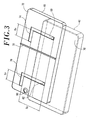
Upper surface 50 may be divided into a first area from the lower side to a distance Ly, and a second area from that position to the upper side.Main keys 52,cursor key 54 and enter key 56 are all provided in the first area. Sub-display 58 andprojections - Fig. 3 schematically shows a structure of a
rear surface 72 offirst housing 40. Referring to Fig. 3, onrear surface 72 offirst housing 40, a pair of L-shaped slide guides 74 and 76 forming a part of the coupling mechanism described above, and anFPC guide 78 for regulating lateral movement of a flexible printed board (not shown) for electrical connection between the first andsecond housings rear surface 72, a camera lens 80 is provided. Camera lens 80 is normally unexposed, and it is exposed whenPDA 30 is set to the second and third postures. When the camera is to be used in the second posture,main display 46 shown in Fig. 1 is used as a finder, and when it is used in the third posture,main display 46 may be turned off and sub-display 58 may be used as a finder. - As shown by chain-dotted lines in Fig. 3,
projection 60 engages withslide guide 74, andprojection 62 engages withslide guide 76, whereby a dual-slide mechanism coupling the second andfirst housings second housing 42. Whenprojections PDA 30 is in the second posture shown in Fig. 1(A); when they are at the tip ends of shorter sides,PDA 30 is in the third posture shown in Fig. 1(C); and whenprojections 62 and 64 are at the bent portions of slide guides 74 and 76,PDA 30 is in the first posture shown in Fig. 1(B). Therefore, the distance between the shorter side portions of slide guides 74 and 76 shown in Fig. 3 to the upper side ofrear surface 72 offirst housing 40 is approximately the same as the distance betweenprojections upper surface 50 of thesecond housing 42. Transition from the first posture to the second posture through translation is realized by the first translation mechanism, and transition between the first and third postures through translation is realized by the second translation mechanism. - When we represent the length of longer side portions of slide guides 74 and 76 by Gy and the length of shorter side portions by Gx, the following relation holds:


-
FPC guide 78 is formed slightly to the right from the center in Fig. 3 ofrear surface 72 offirst housing 40, to be parallel to the shorter side offirst housing 40 and slightly protruding fromrear surface 72.FPC guide 78, together with FPC, will be described later. - Referring to Fig. 1(A), in the second posture, the first housing 80 is moved upward as shown in the figure by the distance Ly, and therefore,
main keys 52,cursor key 54 and enter key 56 are exposed. In this state, text input is possible usingmain keys 52,cursor key 54 and enter key 56 while viewingmain display 46. In the first posture, a relatively large area ofupper surface 50 is exposed, and therefore, a large number ofmain keys 52 may be arranged, allowing high-speed text input. - Referring to Fig. 1(C), in the third posture, the
first housing 40 is slid by the prescribed distance Lx to the left in the figure. As a result, a right end portion ofupper surface 50 of second housing 42 (area having the width Lx) is exposed, allowing operation ofcursor key 54 and enterkey 56, andsub-display 58 is viewable. Of theupper surface 50, the area exposed in this state will be referred to as the third area, and the area not exposed will be referred to as the fourth area. - As shown in Fig. 1(B), when we represent the length of the longer side of
second housing 42 by Cx and the length of shorter side by Cy, the values Gx, Gy, Cx and Cy are selected to satisfy the following relation:
- From Equation (1), it can be understood that, in the present embodiment, the ratio occupied by the length of longitudinal slide with respect to the shorter side of
second housing 42 is larger than the ratio occupied by the length of lateral slide with respect to the longer side. The reason for this is as follows. In the second posture, main operation is expected to be character input, and therefore, it is necessary to expose allmain keys 52. The third posture is not used for character input, and expected use of this posture is TV viewing or playing games. Therefore, it is unnecessary to exposemain keys 52, and it is rather preferred to keepmain keys 52 unexposed. - When two L-shaped slide guides 74 and 76 are formed side by side in the lateral direction as shown in Fig. 3, there is naturally a restriction of Gx < Cx/2 imposed in addition to the restriction of Equation (1). Actually,
main keys 52 occupy most of theupper surface 50. Therefore, in order not to exposemain keys 52 in the third posture, the value Gx should preferably be smaller, to about Gx = Cx/5. - As shown in Fig. 1, even when slide movement between the first and second or first and third postures is to be attained, electronic circuits in the
second housing 42 and thefirst housing 40 must be kept electrically connected. In the present embodiment,FPC 90 having a planer shape such as shown in Fig. 4 is used, interposed between thesecond housing 42 and thefirst housing 40. - Referring to Fig. 4,
FPC 90 consists of a first-housing-side end portion 96 and a second-housing-side end portion 94 parallel to each other and having the same length, and a central portion connecting the end portions. These portions are all flexible and can be freely bent in a direction crossing the plane. - Fig. 5 shows the posture of
FPC 90 inPDA 30 in the state of Fig. 1(B) (first posture). In Figs. 5 to 7 discussed below, longitudinal dimensions are exaggerated to help understand the state ofFPC 90. Referring to Fig. 5, in the first posture, the second-housing-side end portion 94 is reversed to the lower side in the middle, and connected by means of a connector, not shown, to a circuit in thesecond housing 42. The first-housing-side end portion 96 is reversed to the upper side in the middle, and connected by means of a connector, not shown, to a circuit in thefirst housing 40. Thecentral portion 92 is in an extended state. FPC guide 78 described above is formed at a position to be in contact with the longer side ofcentral portion 92 in this state. With the longer side ofcentral portion 92 being in contact withFPC guide 78, movement ofFPC 90 overFPC guide 78 is restricted. - Fig. 6 shows the posture of
FPC 90 inPDA 30 in the state of Fig. 1(A) (second posture). Referring to Fig. 6, in the second posture, the second-housing-side end portion 94 and the first-housing-side end portion 96 maintain the postures similar to Fig. 5, relative to thesecond housing 42 and thefirst housing 40, respectively. On the other hand, the end portion ofcentral portion 92 on the side of first-housing-side end portion 96 is moved, guided byFPC guide 78, by the distance Ly upward to the left in Fig. 6 as the first housing slides and moves. The end portion on the side of second-housing-side end portion 94 is fixed to thesecond housing 42 and, therefore, the end portion is folded at two positions in the middle, as shown in Fig. 6. As a result, even whenPDA 30 is in the second posture, electrical connection between the first andsecond housings FPC 90. For the movement shown in Fig. 6, it is necessary to preventcentral portion 92 from twisting. As theFPC guide 78 is provided to limit lateral movement ofFPC 90 over the guide, the movement such as shown in Fig. 6 becomes possible. - Fig. 7 shows the posture of
FPC 90 inPDA 30 in the state of Fig. 1(C) (third posture). Referring to Fig. 7, in the third posture, as thefirst housing 40 slides to the left, the first-housing-side end portion 96 moves to the left as represented by anarrow 100 and, on the contrary, the second-housing-side end portion 94 moves to the right relative tocentral portion 92, as represented by anarrow 98, withcentral portion 92 kept in the extended state. Then, the movement stops when thefirst housing 40 has moved by the distance Lx relative to thesecond housing 42. - As shown in Figs. 5 to 7, by
FPC 90, electrical connection between thesecond housing 42 and thefirst housing 40 can be maintained in any of the first, second and third postures. -
PDA 30 in accordance with the first embodiment as described above is used in the following manner. By way of example, for receiving TV broadcast and displaying onmain display 46,PDA 30 is set to the first posture shown in Fig. 1(B). In this state, unnecessary buttons and the like are all hidden, and hence, there is no possibility of erroneous operation caused by unintended pressing of any button. - When characters are to be input at high-speed for writing an e-mail or drafting a document, PDA. 30 is used in the second posture shown in Fig. 1(A). Input/output devices for inputting sentences at high speed such as
main keys 52 andcursor key 54 are all available, and therefore, it is possible to form desired sentences at far higher speed than when the number of available keys is limited, as in the case of a conventional portable telephone. - To change a channel while viewing TV broadcast or to change sound volume, or to play a game using
main display 46, the PDA is set to the third posture shown in Fig. 1(C). In the third posture, minimum keys necessary for game operation or TV operation such ascursor key 54 are available while other keys are unexposed. Therefore, there is little possibility of erroneous operation caused by unintended pressing of an unrelated key while viewing TV broadcast or playing a game. Further, in the third posture, it is possible to display, for example, broadcast of a different channel onsub-display 58. Therefore, though it is a portable PDA, it allows the user to enjoy TV broadcast in various different manners. - The space where sub-display 58 is provided would have been an unused dead space if
PDA 30 could assume only the first and second postures. Effective use of the space allows implementation of various functions not available in conventional portable terminals. For instance, by providingsub-display 58 in this space, it becomes possible to confirm an image when the terminal is used as a camera, using not themain display 46 but sub-display 58 of smaller power consumption as the finder. It is unnecessary to provide a sub-display used only as the finder on the surface offirst housing 40, and thus, surfaces of the first andsecond housings - As described above, in
PDA 30 as the portable terminal in accordance with the present embodiment, the first andsecond housings second housing 42 are exposed in different configurations in different states. Specifically, the devices are not at all exposed, most of the devices are exposed or only a part of the devices are exposed. Therefore, any of the three postures described above may be selected in consideration of the types and numbers of the input/output devices to be used, and thus, a portable terminal supporting TV broadcast and relatively free of erroneous operation during use can be provided. - In the embodiment described above, the
first housing 40 entirely covers theupper surface 50 ofsecond housing 42 in the first posture. Therefore, in the first posture, input/output devices are not at all exposed, eliminating possibility of erroneous operation during watching TV broadcast. It is necessary, however, to change the state to the third posture, to switch a channel. - In such a situation, there may naturally be a desire among users to change the channel of TV broadcast while keeping the first posture, even if that leads to a slightly higher possibility of erroneous operation.
- To meet such a demand, a channel switch button, which can be operated in the first posture, may be provided. Fig. 8 shows an appearance of a
PDA 110 as an example having such a button, in the second posture. Referring to Fig. 8,PDA 110 includes, in place of thefirst housing 40 ofPDA 30 in accordance with the first embodiment, afirst housing 112 havingchannel switch buttons main display 46. Though not shown,PDA 110 can assume, similar toPDA 30 in accordance with the first embodiment, the first, second and third postures shown in Fig. 1, by sliding thefirst housing 112 either in the longitudinal direction or lateral direction relative to thesecond housing 42, through translation. -
Channel switch buttons PDA 110. Therefore, even in the first posture, TV broadcasting channel can be switched by operatingchannel switch buttons PDA 110 to the third posture in order to switch the channel. Possibility of erroneous operation naturally increases aschannel switch buttons - In the first embodiment,
sub-display 58 is adopted as an input/output device exposed only in the third posture. The present invention, however, is not limited to such an embodiment, and various other input/output devices may be provided at this position. - Fig. 9 shows an appearance of a
PDA 130 having a function of portable telephone in accordance with a third embodiment, in the third posture.PDA 130 includes first andsecond housings second housings PDA 30 in accordance with the first embodiment. - The
second housing 142 is the same as thesecond housing 42 ofPDA 30, except that in place ofsub-display 58 provided on thesecond housing 42, afingerprint sensor 148 is provided.First housing 140 is the same as thefirst housing 40 ofPDA 30, except that amicrophone 144 and aspeaker 146 are provided on left and right sides of main display 46 (up and down sides whenPDA 130 is used in portrait arrangement), so as to allow use ofPDA 130 as a portable telephone. -
PDA 130 hasfingerprint sensor 148 at the position that is exposed only in the third posture, and higher security is assured utilizing a space not used conventionally. - In any of the embodiments described above, in the first posture, the upper surface of the
second housing first housing second housing PDA 160 having the function of a portable telephone in accordance with the fourth embodiment shown in Fig. 10, a part of the first housing is exposed even in the first posture, and the input/output device existing at that portion can be used. - Fig. 10(B) shows an appearance of
PDA 160 in accordance with the fourth embodiment in the first posture, Fig. 10(A) shows an appearance in the second posture, and Fig. 10(C) shows an appearance in the third posture. - Referring to Fig. 10(B),
PDA 160 includes afirst housing 170 having anupper surface 182 with adisplay 184 provided at the center, and asecond housing 172 having anupper surface 180 havingchannel switch buttons first housing 170 such thatupper surface 180 is covered by thefirst housing 180 except for the left end area wherechannel switch buttons speaker 146 is provided. Different fromPDA 130 shown in Fig. 9, inPDA 160, no speaker is provided onupper surface 182 offirst housing 170. - In
PDA 160, the left end area ofupper surface 180 ofsecond housing 172 is exposed in the first posture. Therefore,channel switch buttons - Referring to Fig. 10(A), by sliding the
first housing 170 upward in the figure,PDA 160 is set to the second posture. In the second posture,main keys 194 provided slightly to the left from the center ofupper surface 180 ofsecond housing 172, cursor key 154 and enter key 56 are exposed. Therefore, in this posture, it is possible to input sentences at a highspeed using display 184,main keys 194,cursor key 54 and enterkey 56. Further, in the second posture also,channel switch buttons PDA 160, while viewing TV ondisplay 184. - Referring to Fig. 10(C), by sliding the
first housing 170 to the left from the first posture,PDA 160 is set to the third posture. In the third posture, in addition tocursor key 54 and enter key 56 provided on theupper surface 180 ofsecond housing 172, the area where sub-display 58 is provided in the first embodiment is exposed. In the present embodiment, amicrophone 196 is provided at this position. Therefore, when longitudinally held in this state,PDA 160 can provide the telephonefunction utilizing microphone 196 andspeaker 146. - In the third posture,
channel switch buttons first housing 170 and, therefore, there is no possibility of pressing these buttons erroneously. - As described above, according to the embodiments of the present invention, in the first posture as the base posture, input/output devices other than the main display are not at all or only partially exposed to the outside. Therefore, possibility of erroneous operation by an unintended touching of an input/output device that is not to be manipulated can be reduced. In the second posture, main keys including a large number of keys are exposed, and
cursor key 54 and enter key 56 are also exposed. High-speed input of sentences becomes possible using these keys and, therefore, this posture is optimal for applications for creating mails and writing sentences. Further, in the third posture, keys larger in number than in the first posture but smaller than in the second posture are exposed. Therefore, it can suitably be used for an application that requires operation of not many buy only a small number of keys, such as an application for telephone function, and possibility of erroneously touching an unintended key during use can be reduced. As a result, the PDA in accordance with the embodiments of the present invention can be used in a form optimal for the function desired by the user, and as a result, optimal input function is realized while possibility of erroneous operation can be reduced. Consequently, the user can comfortably use the PDA without paying much attention to its operation. - The embodiments above are all directed to PDAs. The present invention is applicable not only to PDAs but also to multi-functional portable telephones, remote controllers, portable music players, portable data storage devices and the like, as can be clearly understood from the foregoing description.
- Further, in the embodiments described above, the first and second housings both have flat, approximately rectangular box shapes. The shape of housings is not limited to a rectangular box. For example, the housing may have elliptical or oval planer shape. Further, the first and second housings may not have the same shape.
- The embodiments as have been described here are mere examples and should not be interpreted as restrictive. The scope of the present invention is determined by each of the claims with appropriate consideration of the written description of the embodiments and embraces modifications within the meaning of, and equivalent to, the languages in the claims.
Claims (4)
- A portable terminal, comprising:a first housing having a first surface with a display arranged, and a second surface as a rear surface of said first surface;a second housing having a first surface; anda coupling mechanism coupling said first housing and said second housing to each other; whereinsaid coupling mechanism includesa first translation mechanism coupling said first housing to said second housing in a manner allowing translation movement of said first housing relative to said second housing along a prescribed first trajectory, between a first posture in which said first surface of said second housing is covered by said second surface of said first housing and a second posture in which said first surface of said second housing is exposed, anda second translation mechanism coupling said first housing to said second housing in a manner allowing translation movement of said first housing relative to said second housing along a second trajectory different from said first trajectory, between said first posture and a third posture in which said first surface of said second housing is exposed.
- The portable terminal according to claim 1, wherein
input/output devices for operation of an application using said display are arranged on said first surface of said second housing; and
configuration of the input/output devices exposed in said second posture is different from configuration of the input/output devices exposed in said third posture. - The portable terminal according to claim 1, wherein
said display has an approximately rectangular shape with longer and shorter sides;
said first trajectory is a trajectory forming a line in a direction parallel to said shorter side; and
said second trajectory is a trajectory forming a line in a direction parallel to said longer side. - A portable terminal, comprising :a first housing having a first surface with a display arranged, and a second surface as a rear surface of said first surface;an input device having an operating surface for operation of an application using said display;a first translation mechanism coupling said first housing to said input device in a manner allowing translation movement of said housing along a prescribed first trajectory relative to said input device, between a first posture in which said operating surface is covered by said second surface and a second posture in which said operating surface is exposed; anda second translation mechanism coupling said first housing to said input device in a manner allowing translation movement of said first housing along a second trajectory different from said first trajectory relative to said input device, between said first posture and a third posture in which said operating surface is exposed.
Applications Claiming Priority (1)
| Application Number | Priority Date | Filing Date | Title |
|---|---|---|---|
| JP2006205725A JP5192668B2 (en) | 2006-07-28 | 2006-07-28 | Portable terminal |
Publications (2)
| Publication Number | Publication Date |
|---|---|
| EP1883208A2 true EP1883208A2 (en) | 2008-01-30 |
| EP1883208A3 EP1883208A3 (en) | 2009-12-16 |
Family
ID=38750561
Family Applications (1)
| Application Number | Title | Priority Date | Filing Date |
|---|---|---|---|
| EP07252845A Withdrawn EP1883208A3 (en) | 2006-07-28 | 2007-07-18 | Dual slide portable terminal |
Country Status (6)
| Country | Link |
|---|---|
| US (1) | US8160660B2 (en) |
| EP (1) | EP1883208A3 (en) |
| JP (1) | JP5192668B2 (en) |
| KR (1) | KR101055959B1 (en) |
| CN (1) | CN101115382B (en) |
| TW (1) | TWI334076B (en) |
Cited By (1)
| Publication number | Priority date | Publication date | Assignee | Title |
|---|---|---|---|---|
| EP2290920A3 (en) * | 2009-08-27 | 2013-02-06 | Funai Electric Co., Ltd. | Slidable mobile terminal |
Families Citing this family (39)
| Publication number | Priority date | Publication date | Assignee | Title |
|---|---|---|---|---|
| WO2006020992A2 (en) * | 2004-08-13 | 2006-02-23 | 5 Examples, Inc. | The one-row keyboard and approximate typing |
| US7853301B2 (en) * | 2006-09-19 | 2010-12-14 | Samsung Electronics Co., Ltd | Sliding module for double sliding-type portable communication terminal |
| CN101237478B (en) * | 2007-02-02 | 2012-03-07 | 深圳富泰宏精密工业有限公司 | Portable electronic device |
| JP4752797B2 (en) * | 2007-03-22 | 2011-08-17 | パナソニック株式会社 | Switchgear |
| EP2007116A3 (en) * | 2007-06-22 | 2011-09-14 | Samsung Electronics Co., Ltd. | Sliding of housings used as input for a mobile phone |
| US8099144B2 (en) * | 2007-08-20 | 2012-01-17 | Google Inc. | Electronic device with hinge mechanism |
| US8217964B2 (en) * | 2008-02-14 | 2012-07-10 | Nokia Corporation | Information presentation based on display screen orientation |
| CN101981902A (en) * | 2008-03-27 | 2011-02-23 | 日本电气株式会社 | Communication device, method for displaying function of communication device, and recording medium of program for communication device |
| US20090263052A1 (en) * | 2008-04-22 | 2009-10-22 | Han Sang Lee | Dual sliding apparatus |
| JP5077049B2 (en) * | 2008-04-24 | 2012-11-21 | オンキヨー株式会社 | Display device and computer device provided with the display device |
| CN101568240B (en) * | 2008-04-25 | 2012-07-25 | 深圳富泰宏精密工业有限公司 | Slide cover structure and portable electronic device having same |
| JP2009278411A (en) * | 2008-05-15 | 2009-11-26 | Sony Ericsson Mobilecommunications Japan Inc | Portable device |
| TWI418202B (en) * | 2008-05-30 | 2013-12-01 | Fih Hong Kong Ltd | Slidable mechanism and portable electronic device using the same |
| US8385992B2 (en) * | 2008-12-19 | 2013-02-26 | Nokia Corporation | User interfaces and associated apparatus and methods |
| US8442766B2 (en) * | 2008-10-02 | 2013-05-14 | Certusview Technologies, Llc | Marking apparatus having enhanced features for underground facility marking operations, and associated methods and systems |
| KR101545584B1 (en) * | 2008-11-14 | 2015-08-19 | 엘지전자 주식회사 | Mobile terminal |
| JP5196570B2 (en) * | 2008-12-25 | 2013-05-15 | 日本電気株式会社 | Slide type electronic equipment |
| JP5443830B2 (en) * | 2009-05-26 | 2014-03-19 | 京セラ株式会社 | Mobile terminal and slide control program |
| TWI407758B (en) * | 2009-05-27 | 2013-09-01 | Htc Corp | Electronic device |
| JP5363890B2 (en) | 2009-06-26 | 2013-12-11 | 京セラ株式会社 | Mobile phone |
| JP2011015181A (en) | 2009-07-02 | 2011-01-20 | Funai Electric Co Ltd | Portable terminal device |
| JP2011077660A (en) * | 2009-09-29 | 2011-04-14 | Strawberry Corporation | Slide device and electronic equipment using the same |
| KR20110049633A (en) * | 2009-11-04 | 2011-05-12 | 김시환 | A portable display device |
| US8284554B2 (en) * | 2010-02-15 | 2012-10-09 | Motorola Mobility Llc | Electronic device housing with pivoting and sliding portions |
| CN102188820B (en) * | 2010-03-01 | 2013-09-04 | 致伸科技股份有限公司 | Hand-held electronic device and key input device for same |
| KR101629262B1 (en) * | 2010-05-31 | 2016-06-10 | 엘지전자 주식회사 | Portable terminal |
| JP5636873B2 (en) * | 2010-10-26 | 2014-12-10 | 富士通株式会社 | Enclosure mechanism |
| US8911165B2 (en) | 2011-01-24 | 2014-12-16 | 5 Examples, Inc. | Overloaded typing apparatuses, and related devices, systems, and methods |
| USD701862S1 (en) * | 2011-02-18 | 2014-04-01 | Lg Electronics Inc. | Cart barcode scanner |
| US8427829B2 (en) * | 2011-05-06 | 2013-04-23 | Shin Zu Shing Co., Ltd. | Dual directional sliding hinge and portable device |
| CN202231759U (en) * | 2011-09-15 | 2012-05-23 | 中兴通讯股份有限公司 | Mobile phone |
| KR20130099530A (en) * | 2012-02-29 | 2013-09-06 | 주식회사 팬택 | Slide type mobile device |
| JP5355751B1 (en) * | 2012-06-12 | 2013-11-27 | 株式会社東芝 | Electronic device and control method of electronic device |
| USD740776S1 (en) * | 2013-08-20 | 2015-10-13 | Lg Electronics Inc. | Mobile phone |
| USD740796S1 (en) * | 2013-08-20 | 2015-10-13 | Lg Electronics Inc. | Mobile phone |
| USD750067S1 (en) * | 2014-02-22 | 2016-02-23 | Samsung Electronics Co., Ltd. | Electronic device |
| USD757718S1 (en) * | 2014-02-22 | 2016-05-31 | Samsung Electronics Co., Ltd. | Electronic device |
| USD777700S1 (en) * | 2015-06-30 | 2017-01-31 | Lg Display Co., Ltd. | Mobile phone |
| USD974351S1 (en) * | 2018-06-05 | 2023-01-03 | Compal Electronics, Inc. | Electronic device with slidable display |
Family Cites Families (38)
| Publication number | Priority date | Publication date | Assignee | Title |
|---|---|---|---|---|
| US6542721B2 (en) * | 1999-10-11 | 2003-04-01 | Peter V. Boesen | Cellular telephone, personal digital assistant and pager unit |
| KR20010068807A (en) | 2000-01-10 | 2001-07-23 | 윤종용 | Radiotelephone for visual communication |
| EP1296544B1 (en) | 2000-06-30 | 2011-08-03 | Sanyo Electric Co., Ltd. | Flexible printed circuit board and foldable cell phone terminal |
| JP3964607B2 (en) * | 2000-08-08 | 2007-08-22 | アルプス電気株式会社 | Portable information terminal |
| JP2002368440A (en) * | 2001-06-06 | 2002-12-20 | Toshiba Corp | Folding type electronic device and its flexible board |
| JP2003204383A (en) * | 2001-10-26 | 2003-07-18 | Nec Corp | Portable telephone |
| US6934518B2 (en) * | 2001-11-05 | 2005-08-23 | Quanta Computer Inc. | Mobile phone with a hidden input device |
| US7187363B2 (en) * | 2001-11-30 | 2007-03-06 | Palm, Inc. | Integrated handheld data processing device having a sliding form factor |
| JP3719221B2 (en) * | 2002-02-25 | 2005-11-24 | オムロン株式会社 | Rotating structure for signal relay |
| US20050083642A1 (en) * | 2002-03-08 | 2005-04-21 | Tsuyoshi Senpuku | Mobile communications device, and display-control method and program for mobile communications device |
| KR20040021366A (en) * | 2002-09-04 | 2004-03-10 | 삼성전자주식회사 | Portable information phone with expansion data inputting unit |
| JP4324724B2 (en) * | 2002-12-25 | 2009-09-02 | カシオ計算機株式会社 | Biaxial structure and portable terminal device |
| JP2004222173A (en) | 2003-01-17 | 2004-08-05 | Matsushita Electric Ind Co Ltd | Portable telephone set |
| JP2004297417A (en) * | 2003-03-27 | 2004-10-21 | Sanyo Electric Co Ltd | Portable radio terminal |
| JP2004312846A (en) | 2003-04-04 | 2004-11-04 | Fujikura Ltd | Electrical connector structure, electrical connector device, and seat and harness slack absorber using it |
| JP2005084955A (en) | 2003-09-09 | 2005-03-31 | Hitachi Ltd | Personal digital assistant |
| KR20050038982A (en) * | 2003-10-23 | 2005-04-29 | 삼성전자주식회사 | Sliding/swing type portable digital communication device |
| GB2407933B (en) * | 2003-11-06 | 2006-03-08 | Inventec Appliances Corp | Hand-held communication electronic apparatus having two slidable keypads |
| US7907121B2 (en) * | 2003-11-19 | 2011-03-15 | Qualcomm Incorporated | Portable device with versatile keyboard |
| KR100704031B1 (en) | 2004-04-29 | 2007-04-04 | 삼성전자주식회사 | Double sliding-type portable communication device |
| KR100703418B1 (en) * | 2004-05-06 | 2007-04-03 | 삼성전자주식회사 | Sliding/folding combination type portable telephone |
| JP4345005B2 (en) * | 2004-05-31 | 2009-10-14 | 京セラ株式会社 | Mobile device |
| JP2006019925A (en) | 2004-06-30 | 2006-01-19 | Sharp Corp | Portable information terminal, its switching operation method, and its displaying method |
| KR100616197B1 (en) * | 2004-08-24 | 2006-08-25 | 삼성전자주식회사 | Sliding apparatus for double sliding-type portable communication device |
| US7142420B2 (en) * | 2004-09-20 | 2006-11-28 | Qualcomm, Incorporated | Devices and methods for controlling relative movement between layers of an electronic device |
| KR100623414B1 (en) * | 2004-10-12 | 2006-09-19 | 조영길 | Sliding type portable phone |
| KR20060032382A (en) | 2004-10-12 | 2006-04-17 | 주식회사 팬택앤큐리텔 | A slide type of mobile communication terminal |
| JP2006125429A (en) * | 2004-10-26 | 2006-05-18 | Omron Corp | Excessive rotation preventing structure for rotation supporting mechanism and portable remote terminal |
| US7671836B2 (en) | 2005-01-03 | 2010-03-02 | Nokia Corporation | Cell phone with shiftable keypad |
| KR100630869B1 (en) | 2005-03-29 | 2006-10-02 | 주식회사 케이티프리텔 | Mobile phone |
| KR100652718B1 (en) * | 2005-04-04 | 2006-12-01 | 엘지전자 주식회사 | Gear driving type slide module of mobile communication terminal and driving method thereof |
| US9203938B2 (en) * | 2005-04-06 | 2015-12-01 | Nokia Technologies Oy | Extensible mobile electronic device |
| US20070142101A1 (en) * | 2005-08-23 | 2007-06-21 | Sudhir Seshagiri | Mobile electronic device having a rotatable keypad |
| KR101143697B1 (en) | 2005-08-26 | 2012-05-09 | 엘지전자 주식회사 | 2 direction manual slide module for mobile terminal |
| KR100685388B1 (en) * | 2005-10-07 | 2007-02-22 | 삼성전자주식회사 | Curved sliding-type mobile phone and sliding device thereof |
| US7809414B2 (en) | 2005-12-14 | 2010-10-05 | Sharp Kabushiki Kaisha | Portable information terminal, opening/closing operation method, and display method |
| US7636591B2 (en) * | 2006-04-28 | 2009-12-22 | Sony Ericsson Mobile Communications Ab | Two-way sliding mobile terminal |
| US7720446B2 (en) * | 2006-05-16 | 2010-05-18 | Nokia Corporation | Multi-position device |
-
2006
- 2006-07-28 JP JP2006205725A patent/JP5192668B2/en not_active Expired - Fee Related
-
2007
- 2007-07-02 TW TW096124033A patent/TWI334076B/en not_active IP Right Cessation
- 2007-07-18 EP EP07252845A patent/EP1883208A3/en not_active Withdrawn
- 2007-07-23 US US11/878,227 patent/US8160660B2/en not_active Expired - Fee Related
- 2007-07-27 KR KR1020070075431A patent/KR101055959B1/en not_active IP Right Cessation
- 2007-07-30 CN CN2007101371174A patent/CN101115382B/en not_active Expired - Fee Related
Non-Patent Citations (1)
| Title |
|---|
| None |
Cited By (1)
| Publication number | Priority date | Publication date | Assignee | Title |
|---|---|---|---|---|
| EP2290920A3 (en) * | 2009-08-27 | 2013-02-06 | Funai Electric Co., Ltd. | Slidable mobile terminal |
Also Published As
| Publication number | Publication date |
|---|---|
| CN101115382B (en) | 2011-05-18 |
| US20080051161A1 (en) | 2008-02-28 |
| JP5192668B2 (en) | 2013-05-08 |
| TWI334076B (en) | 2010-12-01 |
| KR20080011103A (en) | 2008-01-31 |
| EP1883208A3 (en) | 2009-12-16 |
| TW200819953A (en) | 2008-05-01 |
| US8160660B2 (en) | 2012-04-17 |
| KR101055959B1 (en) | 2011-08-09 |
| JP2008033595A (en) | 2008-02-14 |
| CN101115382A (en) | 2008-01-30 |
Similar Documents
| Publication | Publication Date | Title |
|---|---|---|
| US8160660B2 (en) | Dual slide portable terminal | |
| JP4227994B2 (en) | Foldable mobile device | |
| EP1665737B1 (en) | Communication device having multiple keypads | |
| EP1898605B1 (en) | Key input device for a portable communications apparatus and a sliding module therefor | |
| US7797026B2 (en) | Portable electric device | |
| US20140320416A1 (en) | Terminal device with display function | |
| US20050250561A1 (en) | Two-way folder-type terminal | |
| EP1746808B1 (en) | Sliding and swing portable terminal | |
| US7818038B2 (en) | Handheld electronic apparatus with multiple operational configurations | |
| KR100800827B1 (en) | Flip-up type mobile phone | |
| KR100664169B1 (en) | Slide type mobile communication terminal | |
| CN1985501A (en) | Folding rotary portable terminal | |
| US20080039214A1 (en) | Portable terminal having game function | |
| JP4795914B2 (en) | Electronics | |
| KR101117783B1 (en) | Mobile communication terminal with keys increased | |
| JP4228029B2 (en) | Foldable mobile device | |
| JP2007537657A (en) | Electronic device and wireless communication device | |
| WO2007129470A1 (en) | Portable information terminal device | |
| JP2008067409A (en) | Foldable cellular phone | |
| KR20070103564A (en) | Personal portable device of folder type having swing hinge therein |
Legal Events
| Date | Code | Title | Description |
|---|---|---|---|
| PUAI | Public reference made under article 153(3) epc to a published international application that has entered the european phase |
Free format text: ORIGINAL CODE: 0009012 |
|
| AK | Designated contracting states |
Kind code of ref document: A2 Designated state(s): AT BE BG CH CY CZ DE DK EE ES FI FR GB GR HU IE IS IT LI LT LU LV MC MT NL PL PT RO SE SI SK TR |
|
| AX | Request for extension of the european patent |
Extension state: AL BA HR MK YU |
|
| PUAL | Search report despatched |
Free format text: ORIGINAL CODE: 0009013 |
|
| AK | Designated contracting states |
Kind code of ref document: A3 Designated state(s): AT BE BG CH CY CZ DE DK EE ES FI FR GB GR HU IE IS IT LI LT LU LV MC MT NL PL PT RO SE SI SK TR |
|
| AX | Request for extension of the european patent |
Extension state: AL BA HR MK RS |
|
| AKX | Designation fees paid |
Designated state(s): GB |
|
| 17P | Request for examination filed |
Effective date: 20100616 |
|
| REG | Reference to a national code |
Ref country code: DE Ref legal event code: 8566 |
|
| 17Q | First examination report despatched |
Effective date: 20101129 |
|
| STAA | Information on the status of an ep patent application or granted ep patent |
Free format text: STATUS: THE APPLICATION IS DEEMED TO BE WITHDRAWN |
|
| 18D | Application deemed to be withdrawn |
Effective date: 20160928 |