EP1882958A1 - Superconducting magnet apparatus and magnetic resonance imaging apparatus - Google Patents
Superconducting magnet apparatus and magnetic resonance imaging apparatus Download PDFInfo
- Publication number
- EP1882958A1 EP1882958A1 EP07252905A EP07252905A EP1882958A1 EP 1882958 A1 EP1882958 A1 EP 1882958A1 EP 07252905 A EP07252905 A EP 07252905A EP 07252905 A EP07252905 A EP 07252905A EP 1882958 A1 EP1882958 A1 EP 1882958A1
- Authority
- EP
- European Patent Office
- Prior art keywords
- coil
- vessel
- magnetic material
- thermal shield
- magnetic
- Prior art date
- Legal status (The legal status is an assumption and is not a legal conclusion. Google has not performed a legal analysis and makes no representation as to the accuracy of the status listed.)
- Granted
Links
- 238000002595 magnetic resonance imaging Methods 0.000 title claims description 24
- 239000000696 magnetic material Substances 0.000 claims abstract description 82
- 230000005291 magnetic effect Effects 0.000 claims abstract description 48
- 238000009413 insulation Methods 0.000 claims abstract description 5
- 239000003507 refrigerant Substances 0.000 claims abstract 3
- UFHFLCQGNIYNRP-UHFFFAOYSA-N Hydrogen Chemical compound [H][H] UFHFLCQGNIYNRP-UHFFFAOYSA-N 0.000 description 8
- 238000005481 NMR spectroscopy Methods 0.000 description 8
- 239000001257 hydrogen Substances 0.000 description 8
- 229910052739 hydrogen Inorganic materials 0.000 description 8
- 230000003068 static effect Effects 0.000 description 7
- 229920002430 Fibre-reinforced plastic Polymers 0.000 description 5
- 239000011151 fibre-reinforced plastic Substances 0.000 description 5
- 229910052751 metal Inorganic materials 0.000 description 5
- 239000002184 metal Substances 0.000 description 5
- TXEYQDLBPFQVAA-UHFFFAOYSA-N tetrafluoromethane Chemical compound FC(F)(F)F TXEYQDLBPFQVAA-UHFFFAOYSA-N 0.000 description 5
- 238000012546 transfer Methods 0.000 description 5
- 238000006073 displacement reaction Methods 0.000 description 4
- 238000000034 method Methods 0.000 description 4
- 230000035945 sensitivity Effects 0.000 description 4
- 230000004913 activation Effects 0.000 description 3
- 238000001816 cooling Methods 0.000 description 3
- 230000007423 decrease Effects 0.000 description 3
- 239000001307 helium Substances 0.000 description 3
- 229910052734 helium Inorganic materials 0.000 description 3
- SWQJXJOGLNCZEY-UHFFFAOYSA-N helium atom Chemical compound [He] SWQJXJOGLNCZEY-UHFFFAOYSA-N 0.000 description 3
- 239000007788 liquid Substances 0.000 description 3
- 230000008569 process Effects 0.000 description 3
- 230000008901 benefit Effects 0.000 description 2
- 238000004891 communication Methods 0.000 description 2
- 239000010949 copper Substances 0.000 description 2
- 230000009849 deactivation Effects 0.000 description 2
- 238000010586 diagram Methods 0.000 description 2
- 239000000463 material Substances 0.000 description 2
- 230000002035 prolonged effect Effects 0.000 description 2
- 238000010791 quenching Methods 0.000 description 2
- 230000000171 quenching effect Effects 0.000 description 2
- RYGMFSIKBFXOCR-UHFFFAOYSA-N Copper Chemical compound [Cu] RYGMFSIKBFXOCR-UHFFFAOYSA-N 0.000 description 1
- 229910052782 aluminium Inorganic materials 0.000 description 1
- XAGFODPZIPBFFR-UHFFFAOYSA-N aluminium Chemical compound [Al] XAGFODPZIPBFFR-UHFFFAOYSA-N 0.000 description 1
- 238000004458 analytical method Methods 0.000 description 1
- 229910052802 copper Inorganic materials 0.000 description 1
- 230000000694 effects Effects 0.000 description 1
- 230000005672 electromagnetic field Effects 0.000 description 1
- 239000003302 ferromagnetic material Substances 0.000 description 1
- 238000007654 immersion Methods 0.000 description 1
- 238000010030 laminating Methods 0.000 description 1
- 238000005259 measurement Methods 0.000 description 1
- 150000002739 metals Chemical class 0.000 description 1
- 239000004033 plastic Substances 0.000 description 1
- 229920003023 plastic Polymers 0.000 description 1
- 238000012545 processing Methods 0.000 description 1
- 230000005855 radiation Effects 0.000 description 1
- 230000009467 reduction Effects 0.000 description 1
- 230000002123 temporal effect Effects 0.000 description 1
Images





Classifications
-
- G—PHYSICS
- G01—MEASURING; TESTING
- G01R—MEASURING ELECTRIC VARIABLES; MEASURING MAGNETIC VARIABLES
- G01R33/00—Arrangements or instruments for measuring magnetic variables
- G01R33/20—Arrangements or instruments for measuring magnetic variables involving magnetic resonance
- G01R33/28—Details of apparatus provided for in groups G01R33/44 - G01R33/64
- G01R33/38—Systems for generation, homogenisation or stabilisation of the main or gradient magnetic field
- G01R33/381—Systems for generation, homogenisation or stabilisation of the main or gradient magnetic field using electromagnets
- G01R33/3815—Systems for generation, homogenisation or stabilisation of the main or gradient magnetic field using electromagnets with superconducting coils, e.g. power supply therefor
-
- G—PHYSICS
- G01—MEASURING; TESTING
- G01R—MEASURING ELECTRIC VARIABLES; MEASURING MAGNETIC VARIABLES
- G01R33/00—Arrangements or instruments for measuring magnetic variables
- G01R33/20—Arrangements or instruments for measuring magnetic variables involving magnetic resonance
- G01R33/28—Details of apparatus provided for in groups G01R33/44 - G01R33/64
- G01R33/38—Systems for generation, homogenisation or stabilisation of the main or gradient magnetic field
- G01R33/3804—Additional hardware for cooling or heating of the magnet assembly, for housing a cooled or heated part of the magnet assembly or for temperature control of the magnet assembly
-
- G—PHYSICS
- G01—MEASURING; TESTING
- G01R—MEASURING ELECTRIC VARIABLES; MEASURING MAGNETIC VARIABLES
- G01R33/00—Arrangements or instruments for measuring magnetic variables
- G01R33/20—Arrangements or instruments for measuring magnetic variables involving magnetic resonance
- G01R33/28—Details of apparatus provided for in groups G01R33/44 - G01R33/64
- G01R33/38—Systems for generation, homogenisation or stabilisation of the main or gradient magnetic field
- G01R33/3806—Open magnet assemblies for improved access to the sample, e.g. C-type or U-type magnets
-
- G—PHYSICS
- G01—MEASURING; TESTING
- G01R—MEASURING ELECTRIC VARIABLES; MEASURING MAGNETIC VARIABLES
- G01R33/00—Arrangements or instruments for measuring magnetic variables
- G01R33/20—Arrangements or instruments for measuring magnetic variables involving magnetic resonance
- G01R33/28—Details of apparatus provided for in groups G01R33/44 - G01R33/64
- G01R33/38—Systems for generation, homogenisation or stabilisation of the main or gradient magnetic field
- G01R33/387—Compensation of inhomogeneities
- G01R33/3873—Compensation of inhomogeneities using ferromagnetic bodies ; Passive shimming
Definitions
- the present invention relates to a superconducting magnet apparatus and a magnetic resonance imaging (hereinafter referred to as MRI) apparatus using the superconducting magnet apparatus. More particularly, the present invention is concerned with an open-type superconducting magnet apparatus suitable for MRI analysis which does not give a cooped-up feeling to a subject to be inspected and an MRI apparatus using the open-type superconducting magnet apparatus.
- MRI magnetic resonance imaging
- An MRI apparatus measures an electromagnetic wave emitted by hydrogen atomic nucleus spin according to a phenomenon of nuclear magnetic resonance (hereinafter referred to as NMR) and processes the electromagnetic wave as a signal to make a tomogram of the subject's body based on the hydrogen atomic nucleus density.
- NMR nuclear magnetic resonance
- a superconducting magnet apparatus is used to generate a static magnetic field with high intensity. Furthermore, in order to eliminate distortion of the tomogram with high definition and high resolution, it is necessary to increase the magnetic field uniformity of the uniform magnetic field region. Then, a magnetic material is arranged in the superconducting magnet apparatus as a method for increasing the intensity of the static magnetic field in the uniform magnetic field region and improving the magnetic field uniformity.
- An MRI apparatus which comprises the magnetic material located in a coil vessel filled with ultracold temperature liquid helium for cooling a superconducting coil, although the magnetic material is generally arranged in the atmosphere at normal temperature, is proposed (for example, in JP-A-2001-224571 and JP-A-10-97917 ). Furthermore, an MRI apparatus, which comprises the magnetic material located in an intermediate-to-low temperature thermal shield system arranged for surrounding an ultracold temperature coil vessel and for shielding radiant heat from a vacuum vessel, is also proposed (for example, JP-A-2005-144132 ).
- the present invention is made in the light of the above-mentioned problems. It is an aim of the present invention to provide a superconducting magnet apparatus and an MRI apparatus which make it possible to obtain high magnetic field uniformity, without increasing the volume of the magnetic material even for room temperature variation, vibration, refrigerator deactivation due to power failure, and other disturbances.
- a superconducting electromagnet and an MRI apparatus of the present invention are characterized in that the load of the magnetic material is supported so as to insulate heat from the coil vessel and located in a vacuum inside the vacuum vessel.
- an open-type MRI apparatus can be mentioned as an MRI (magnetic resonance imaging) apparatus 1.
- the open-type MRI apparatus includes a superconducting magnet apparatus 2, a bed 6 for laying out a subject, and a control unit 7.
- the superconducting magnet apparatus 2 includes two (top and bottom) vacuum vessels 3. Two support member 4 are stuck up on the bottom vacuum vessel 3, and the top vacuum vessel 3 is supported by these support members 4. Since a subject to be inspected is laid down between the top and bottom vacuum vessels 3 spaced apart by the support members 4 to provide medical care, the open-type MRI apparatus provides an open sight and is well-received by subjects.
- Each of the top and bottom vacuum vessels 3 is a cylindrical tube having the Z axis as a common center axis.
- the shapes of the top and bottom vacuum vessels 3 are plane symmetry with each other with respect to the R plane having the Z axis as a normal line.
- the superconducting magnet apparatus 2 includes a circularly-arranged superconducting coil 11 which generates a magnetic field by drawing a permanent current for each of the top and bottom vacuum vessels 3 and has a center axis corresponding to the Z axis, a coil vessel 9 which contains the superconducting coil 11 together with refrigerant 14, and a thermal shield 8 arranged so as to surround the coil vessel 9, wherein each of the top and bottom vacuum vessels 3 surrounds the thermal shield 8 to keep the inside vacuum.
- the refrigerant 14 directly cools the superconducting coil 11. Liquid helium (He) is used as the refrigerant 14.
- the coil vessel 9 is arranged circularly having the Z axis as a center axis so as to curve along the circularly-arranged superconducting coil 11 to contain it, thus minimizing the capacity.
- the thermal shield 8 is arranged circularly having the Z axis as a center axis so as to curve along the circularly-arranged coil vessel 9 to cover it, thus minimizing the surface area to block heat of immersion.
- the thermal shield 8 is cooled by a refrigerator, absorbs radiant heat from the vacuum vessel 3, and discharges it to the refrigerator. Therefore, the coil vessel 9 is not heated by the radiant heat. It is preferable to set the thermal shield 8 to an intermediate-to-low temperature between the temperature of the refrigerant 14 (ultracold temperature) and the room temperature.
- the superconducting coil 11 and the coil vessel 9 can be stably set to the ultracold temperature of the refrigerant 14.
- Each vacuum vessel 3 includes magnetic materials (ferromagnetic materials for correcting magnetic field) 12 and 13 for correcting a generated magnetic field and forming a uniform magnetic field region (FOV: field of view) 34.
- the magnetic material 12 is arranged circularly having the Z axis as a center axis, and the outer diameter thereof is smaller than the inner diameter of the superconducting coil 11.
- the magnetic material 13 is arranged cylindrically having the Z axis as a center axis, and the diameter thereof is smaller than the inner diameter of the magnetic material 12.
- the superconducting magnet apparatus 2 is configured almost in symmetrical structure having the Z axis as a symmetrical axis and the R plane as a symmetrical plane.
- the top and bottom vacuum vessels 3 communicate with each other through the support members 4.
- the coil vessel 9 contained in each of the top and bottom vacuum vessels 3 is provided with communication holes 20 so as to communicate with each other through the support members 4.
- the thermal shield 8 contained in each of the top and bottom vacuum vessels 3 is connected with each other within the support members 4 so as to cover the periphery of the communication holes 20.
- the superconducting coil 11 is supported by the coil vessel 9, and the thermal shield 8 is also supported by the coil vessel 9.
- the coil vessel 9 having a large total load is supported by the vacuum vessels 3 used as a base.
- a radio frequency coil 5 and a gradient coil 31 are located in a recessed section on respective facing side of the top and bottom vacuum vessels 3.
- the MRI apparatus 1 measures a nuclear magnetic resonance signal emitted by hydrogen atomic nucleus spin according to the NMR phenomenon and processes the nuclear magnetic resonance signal to make a tomogram of the subject's body based on the hydrogen atomic nucleus density.
- a static magnetic field having high intensity (0.2T or more) and high static magnetic field uniformity, is formed in the field of view 34 in which the subject is laid down.
- a pair of the top and bottom gradient coils 31 in the field of view 34 applies a gradient magnetic field, having spatially changed magnetic field, to the field of view 34 in order to obtain positional information in the field of view 34.
- a pair of the top and bottom radio frequency coils 5 in the field of view 34 applies an electromagnetic wave, having a resonance frequency for causing the NMR phenomenon, to the field of view 34.
- an electromagnetic wave having a resonance frequency for causing the NMR phenomenon
- the magnetic materials 12 and 13 are connected and integrated by a non-magnetic metal connection member 17.
- the load of the integrated magnetic materials 12 and 13 is supported by the coil vessel 9 through a heat-insulation support medium 15.
- the support medium 15 is made of such a material that reduces heat transfer from the magnetic materials 12 and 13 to the coil vessel 9.
- a fiber-reinforced plastic (FRP) pipe with a low thermal conductivity can be used as the support medium 15.
- FRP fiber-reinforced plastic
- the support medium 15 is stuck up vertically in parallel with the Z axis.
- One end of the support medium 15 is fixed to the connection member 17 and the other end to the coil vessel 9 through a non-magnetic metal connection member 16.
- the connection member 16 connects the support medium 15 and the coil vessel 9.
- the magnetic materials 12 and 13 are supported by the support medium 15.
- the thermal shield 8 is provided with a thermal shield cover 18 to cover the connection member 16.
- the thermal shield cover 18 is provided with a hole 23 and the support medium 15 extends through the hole 23.
- the magnetic material 13 is supported by the coil vessel 9 through the heat-insulation support medium 25 in order to suppress movement in a direction perpendicular to a loading direction to the integrated magnetic materials 12 and 13.
- the support medium 25 is made of a material, such as FRP, which reduces heat transfer from the magnetic materials 12 and 13 to the coil vessel 9 in order to support the magnetic materials 12 and 13 at room temperature from the ultracold temperature coil vessel 9.
- the support medium 25 may be not only pipe-shaped but also plate- or rod-shaped.
- the support medium 25 is laid down in the horizontal direction which perpendicularly intersects with the Z axis.
- connection member 26 connects the support medium 25 and the coil vessel 9.
- the magnetic materials 12 and 13 are supported by the support medium 25 to avoid deflection to the Z axis.
- the thermal shield 8 is provided with a thermal shield cover 28 to cover the connection member 26.
- the thermal shield cover 28 is provided with a hole 24 and the support medium 25 extends through the hole 24.
- the magnetic materials 12 and 13 are arranged in a vacuum inside the vacuum vessel 3. However, the magnetic materials 12 and 13 are arranged on the outside of the thermal shield 8. Therefore, the temperature of the magnetic materials 12 and 13 becomes almost the same as the room temperature because of radiant heat from the vacuum vessel 3.
- the magnetic materials 12 and 13 are supported so as to insulate heat from the ultracold temperature coil vessel 9, it is possible to maintain the temperature of the magnetic materials 12 and 13 almost at room temperature. At this time, the temperature of the magnetic materials 12 and 13 is not affected by temperature variation of the vacuum vessel 3 due to temporal variation of room temperature because of a large heat capacity of the magnetic materials 12 and 13, leaving positions and dimensions of the magnetic materials 12 and 13 unchanged.
- thermal anchor at a halfway point in the longitudinal direction of the support media 15 and 25, from which heat transfer elastic media 19 and 29 are respectively connected to the thermal shield 8.
- the heat transfer elastic media 19 and 29 cannot mutually support the loads of the support media 15 and 25 and the thermal shield 8 respectively connected to both ends, they conduct heat well and the temperature of the halfway point of the support media 15 and 25 is set to the temperature of the thermal shield 8. This stops heat flow to the ultracold temperature coil vessel 9 caused by heat transfer ranging from room temperature to ultracold temperature from one end to the other of the support media 15 and 25.
- the second embodiment differs from the first embodiment shown in Fig. 2 and Fig. 4 in that the magnetic materials 12 and 13 are connected with the vacuum vessel 3 through thermal conducting leads 32 and 33, respectively.
- the thermal conducting leads 32 and 33 cannot mutually support the loads of the vacuum vessel 3 and the magnetic materials 12 and 13 respectively connected to both ends, they conduct heat well. This allows heat in the vacuum vessel 3 to transmit to the magnetic materials 12 and 13 not only through radiation but also through conduction of the thermal conducting leads 32 and 33. Therefore, the temperature of the magnetic materials 12 and 13 can be set more quickly almost to the temperature of the vacuum vessel 3, i.e., the room temperature.
- the room temperature also fluctuates with a period of one day, it is not desirable that the temperature of the magnetic materials 12 and 13 follows the fluctuation of room temperature.
- a thermal time constant time necessary for temperature difference between the vacuum vessel 3 and the magnetic materials 12 and 13 to decrease to 30%
- the thermal time constant of the thermal conducting leads 32 and 33 can be changed by adjusting the number, the cross-sectional area, and the length of the thermal conducting leads 32 and 33.
- the temperature of the magnetic materials 12 and 13 can easily be made constant at room temperature also by presetting the initial temperature of the magnetic materials 12 and 13 to room temperature before transportation.
- the thermal conducting leads 32 and 33 are elastic metals having a small elastic modulus. By giving the flexibility to the thermal conducting leads 32 and 33, it is possible to prevent vibration of the magnetic materials 12 and 13 being affected by vibration of the vacuum vessel 3, thus avoiding variation of the magnetic field uniformity.
- Examples of the thermal conducting leads 32 and 33 include a wire and a thin laminating plate made of copper (Cu) and aluminum (Al).
- the magnetic materials 12 and 13 are supported so as to insulate heat from the coil vessel 9 in the vacuum vessel 3, magnetic field variation can be reduced against disturbances like the first embodiment.
Landscapes
- Physics & Mathematics (AREA)
- Condensed Matter Physics & Semiconductors (AREA)
- General Physics & Mathematics (AREA)
- Electromagnetism (AREA)
- Magnetic Resonance Imaging Apparatus (AREA)
Abstract
Description
- The present invention relates to a superconducting magnet apparatus and a magnetic resonance imaging (hereinafter referred to as MRI) apparatus using the superconducting magnet apparatus. More particularly, the present invention is concerned with an open-type superconducting magnet apparatus suitable for MRI analysis which does not give a cooped-up feeling to a subject to be inspected and an MRI apparatus using the open-type superconducting magnet apparatus.
- An MRI apparatus measures an electromagnetic wave emitted by hydrogen atomic nucleus spin according to a phenomenon of nuclear magnetic resonance (hereinafter referred to as NMR) and processes the electromagnetic wave as a signal to make a tomogram of the subject's body based on the hydrogen atomic nucleus density. To measure the electromagnetic wave emitted by hydrogen atomic nucleus spin, it is necessary to generate a uniform magnetic field region having high intensity and high static magnetic field uniformity as a measurement area.
- Since the intensity of an electromagnetic field by the electromagnetic wave emitted by hydrogen atomic nucleus spin is proportional to the intensity of the static magnetic field in the uniform magnetic field region, it is necessary to increase the intensity of the static magnetic field in order to improve the resolution of the tomogram. Therefore, a superconducting magnet apparatus is used to generate a static magnetic field with high intensity. Furthermore, in order to eliminate distortion of the tomogram with high definition and high resolution, it is necessary to increase the magnetic field uniformity of the uniform magnetic field region. Then, a magnetic material is arranged in the superconducting magnet apparatus as a method for increasing the intensity of the static magnetic field in the uniform magnetic field region and improving the magnetic field uniformity.
- An MRI apparatus, which comprises the magnetic material located in a coil vessel filled with ultracold temperature liquid helium for cooling a superconducting coil, although the magnetic material is generally arranged in the atmosphere at normal temperature, is proposed (for example, in
JP-A-2001-224571 JP-A-10-97917 JP-A-2005-144132 - However, when arranging a magnetic material in the atmosphere at normal temperature, it is thought that the following two problems arise.
- (1) As the temperature changes with varying room temperature, the magnetic material arranged in the atmosphere at normal temperature expands and contracts resulting in dimensional displacement. It is thought that the magnetic field uniformity changes due to this displacement.
- (2) For vibration when a permanent current is applied to a superconducting coil and vibration from outside, a relative displacement between a coil vessel of a superconducting magnet apparatus and a vacuum vessel for storing the coil vessel is unavoidable. In this case, it is thought that, if a magnetic material exists in the atmosphere at normal temperature, a relative displacement arises between the position of the superconducting coil in the coil vessel and the magnetic material resulting in variation of the magnetic field uniformity.
The above-mentioned problems (1) and (2) may be solved by arranging a magnetic material in the coil vessel as proposed inJP-A-2001-224571 JP-A-10-97917 - (3) Since the coil vessel is located in a thermal shield plate in the vacuum vessel, the magnetic material will inevitably deviate from the center axis of the superconducting coil by the gap between the thermal shield plate and the coil vessel and the thickness of the thermal shield plate and the coil vessel. Therefore, the influential sensitivity to the magnetic field on the center axis of the superconducting coil by the magnetic material decreases, making it necessary to increase the volume of the magnetic material in order to increase the sensitivity, resulting in an increase in magnet weight. In some cases, it is thought that acquisition of a required sensitivity becomes difficult even if the volume is increased.
Furthermore, when arranging a magnetic material on a thermal shield plate shown inJP-A-2005-144132 - (4) Since the heat capacity of the thermal shield plate will virtually increase, there arises a problem that an initial cooling process takes time. Furthermore, if a refrigerator for cooling the thermal shield plate stops because of power failure, the temperature of the thermal shield plate and the magnetic material rises. However, it is thought that the temperature of the magnetic material which once went up does not easily decrease and the magnetic field uniformity changes over a prolonged period of time.
- The present invention is made in the light of the above-mentioned problems. It is an aim of the present invention to provide a superconducting magnet apparatus and an MRI apparatus which make it possible to obtain high magnetic field uniformity, without increasing the volume of the magnetic material even for room temperature variation, vibration, refrigerator deactivation due to power failure, and other disturbances.
- Thus, a superconducting
electromagnet and an MRI apparatus of the present invention are characterized in that the load of the magnetic material is supported so as to insulate heat from the coil vessel and located in a vacuum inside the vacuum vessel. - In accordance with a thus-configured superconducting electromagnet and MRI apparatus, it is possible to provide a superconducting magnet apparatus and an MRI apparatus which can give high magnetic field uniformity without increasing the volume of the magnetic material even for disturbances.
- Other objects and advantages of the invention will become apparent from the following description of embodiments with reference to the accompanying drawings in which:
- Fig. 1 is a perspective view showing a magnetic resonance imaging apparatus according to a first embodiment of the present invention.
- Fig. 2 is a perspective diagram from above a superconducting magnet apparatus according to the first embodiment.
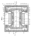
- Fig. 3 is a sectional view taken along the A-A line of Fig. 2.
- Fig. 4 shows an upper half of the sectional view taken along the B-B line of Fig. 2.
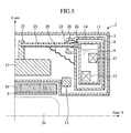
- Fig. 5 shows an upper half of the sectional view taken along the C-C line of Fig. 2.
- Fig. 6 is a perspective diagram from above a superconducting magnet apparatus of the second embodiment.
- Fig. 7 is a sectional view taken along the D-D line of Fig. 6.
- Embodiments of the present invention will be described below in detail with reference to the accompanying drawings as required.
- As shown in Fig. 1, an open-type MRI apparatus can be mentioned as an MRI (magnetic resonance imaging)
apparatus 1. The open-type MRI apparatus includes asuperconducting magnet apparatus 2, abed 6 for laying out a subject, and acontrol unit 7. Thesuperconducting magnet apparatus 2 includes two (top and bottom)vacuum vessels 3. Twosupport member 4 are stuck up on thebottom vacuum vessel 3, and thetop vacuum vessel 3 is supported by thesesupport members 4. Since a subject to be inspected is laid down between the top andbottom vacuum vessels 3 spaced apart by thesupport members 4 to provide medical care, the open-type MRI apparatus provides an open sight and is well-received by subjects. Each of the top andbottom vacuum vessels 3 is a cylindrical tube having the Z axis as a common center axis. Furthermore, the shapes of the top andbottom vacuum vessels 3 are plane symmetry with each other with respect to the R plane having the Z axis as a normal line. - As shown in Fig. 2 and Fig. 3, the
superconducting magnet apparatus 2 includes a circularly-arrangedsuperconducting coil 11 which generates a magnetic field by drawing a permanent current for each of the top andbottom vacuum vessels 3 and has a center axis corresponding to the Z axis, acoil vessel 9 which contains thesuperconducting coil 11 together withrefrigerant 14, and athermal shield 8 arranged so as to surround thecoil vessel 9, wherein each of the top andbottom vacuum vessels 3 surrounds thethermal shield 8 to keep the inside vacuum. Therefrigerant 14 directly cools thesuperconducting coil 11. Liquid helium (He) is used as therefrigerant 14. Thecoil vessel 9 is arranged circularly having the Z axis as a center axis so as to curve along the circularly-arrangedsuperconducting coil 11 to contain it, thus minimizing the capacity. Likewise, thethermal shield 8 is arranged circularly having the Z axis as a center axis so as to curve along the circularly-arrangedcoil vessel 9 to cover it, thus minimizing the surface area to block heat of immersion. - Even if the
superconducting magnet apparatus 2 is arranged in a room at room temperature, the heat in the room is not transferred to thecoil vessel 9 through conduction or convection current because the inside of thevacuum vessel 3 is vacuum. Furthermore, thethermal shield 8 is cooled by a refrigerator, absorbs radiant heat from thevacuum vessel 3, and discharges it to the refrigerator. Therefore, thecoil vessel 9 is not heated by the radiant heat. It is preferable to set thethermal shield 8 to an intermediate-to-low temperature between the temperature of the refrigerant 14 (ultracold temperature) and the room temperature. Thesuperconducting coil 11 and thecoil vessel 9 can be stably set to the ultracold temperature of therefrigerant 14. - Each
vacuum vessel 3 includes magnetic materials (ferromagnetic materials for correcting magnetic field) 12 and 13 for correcting a generated magnetic field and forming a uniform magnetic field region (FOV: field of view) 34. Themagnetic material 12 is arranged circularly having the Z axis as a center axis, and the outer diameter thereof is smaller than the inner diameter of thesuperconducting coil 11. Themagnetic material 13 is arranged cylindrically having the Z axis as a center axis, and the diameter thereof is smaller than the inner diameter of themagnetic material 12. In this manner, thesuperconducting magnet apparatus 2 is configured almost in symmetrical structure having the Z axis as a symmetrical axis and the R plane as a symmetrical plane. - The top and
bottom vacuum vessels 3 communicate with each other through thesupport members 4. Likewise, thecoil vessel 9 contained in each of the top andbottom vacuum vessels 3 is provided withcommunication holes 20 so as to communicate with each other through thesupport members 4.
Furthermore, thethermal shield 8 contained in each of the top andbottom vacuum vessels 3 is connected with each other within thesupport members 4 so as to cover the periphery of thecommunication holes 20. - The
superconducting coil 11 is supported by thecoil vessel 9, and thethermal shield 8 is also supported by thecoil vessel 9. Thecoil vessel 9 having a large total load is supported by thevacuum vessels 3 used as a base. - A
radio frequency coil 5 and agradient coil 31 are located in a recessed section on respective facing side of the top andbottom vacuum vessels 3. TheMRI apparatus 1 measures a nuclear magnetic resonance signal emitted by hydrogen atomic nucleus spin according to the NMR phenomenon and processes the nuclear magnetic resonance signal to make a tomogram of the subject's body based on the hydrogen atomic nucleus density. At this time, a static magnetic field, having high intensity (0.2T or more) and high static magnetic field uniformity, is formed in the field ofview 34 in which the subject is laid down. A pair of the top and bottom gradient coils 31 in the field ofview 34 applies a gradient magnetic field, having spatially changed magnetic field, to the field ofview 34 in order to obtain positional information in the field ofview 34. Furthermore, a pair of the top and bottom radio frequency coils 5 in the field ofview 34 applies an electromagnetic wave, having a resonance frequency for causing the NMR phenomenon, to the field ofview 34. In this manner, by measuring a nuclear magnetic resonance signal emitted by hydrogen atomic nucleus spin for each minute region in the field ofview 34 and processing the nuclear magnetic resonance signal, it is possible to make a tomogram of the subject's body based on the hydrogen atomic nucleus density. - As shown in Fig. 2 to Fig. 4, the
magnetic materials metal connection member 17. The load of the integratedmagnetic materials coil vessel 9 through a heat-insulation support medium 15. In order to support themagnetic materials coil vessel 9 at liquid helium temperature, thesupport medium 15 is made of such a material that reduces heat transfer from themagnetic materials coil vessel 9. For example, a fiber-reinforced plastic (FRP) pipe with a low thermal conductivity can be used as thesupport medium 15. The same function and effect can also be obtained by using a plate- or rod-shaped FRP instead of a pipe-shaped FRP. Thesupport medium 15 is stuck up vertically in parallel with the Z axis. One end of thesupport medium 15 is fixed to theconnection member 17 and the other end to thecoil vessel 9 through a non-magneticmetal connection member 16. Theconnection member 16 connects thesupport medium 15 and thecoil vessel 9. Themagnetic materials support medium 15. - By locating the
support medium 15 so as to extend through thethermal shield 8, themagnetic materials thermal shield 8 and therefore not covered by thethermal shield 8. Thethermal shield 8 is provided with athermal shield cover 18 to cover theconnection member 16. Thethermal shield cover 18 is provided with ahole 23 and thesupport medium 15 extends through thehole 23. - Furthermore, as shown in Fig. 5 illustrating an upper half of a sectional view taken along the C-C line of Fig. 2, the
magnetic material 13 is supported by thecoil vessel 9 through the heat-insulation support medium 25 in order to suppress movement in a direction perpendicular to a loading direction to the integratedmagnetic materials support medium 25 is made of a material, such as FRP, which reduces heat transfer from themagnetic materials coil vessel 9 in order to support themagnetic materials temperature coil vessel 9. Thesupport medium 25 may be not only pipe-shaped but also plate- or rod-shaped. Thesupport medium 25 is laid down in the horizontal direction which perpendicularly intersects with the Z axis. One end of thesupport medium 25 is fixed to a non-magneticmetal connection member 27 fixed to themagnetic material 13, and the other end to thecoil vessel 9 through a non-magneticmetal connection member 26. Theconnection member 26 connects thesupport medium 25 and thecoil vessel 9. Themagnetic materials support medium 25 to avoid deflection to the Z axis. - By locating the
support medium 25 so as to extend through thethermal shield 8, themagnetic materials thermal shield 8 and therefore not covered by thethermal shield 8. Thethermal shield 8 is provided with athermal shield cover 28 to cover theconnection member 26. Thethermal shield cover 28 is provided with ahole 24 and thesupport medium 25 extends through thehole 24. - The
magnetic materials vacuum vessel 3. However, themagnetic materials thermal shield 8. Therefore, the temperature of themagnetic materials vacuum vessel 3. - Furthermore, since the
magnetic materials temperature coil vessel 9, it is possible to maintain the temperature of themagnetic materials magnetic materials vacuum vessel 3 due to temporal variation of room temperature because of a large heat capacity of themagnetic materials magnetic materials - Since the
magnetic materials thermal shield 8, vibration is not transmitted to each other. Therefore, the temperature of themagnetic materials thermal shield 8, positions and dimensions of themagnetic materials - Therefore, even if the temperature of the
thermal shield 8 rises by refrigerator deactivation due to power failure, variation in the magnetic field uniformity can be suppressed. Furthermore, when quenching thesuperconducting coil 11, for example, excessive electromagnetic force is applied to thethermal shield 8 resulting in plastic deformation. Even if the position of thethermal shield 8 changes, positional relationship between thesuperconducting coil 11 and themagnetic materials - Furthermore, even if a current is drawn in the
gradient coil 31 and an electromagnetic force is applied to thethermal shield 8 by a generated eddy current resulting in vibration, this vibration is not easily transmitted to themagnetic materials thermal shield 8. Therefore, positional relationship between thesuperconducting coil 11 and themagnetic materials - There is a thermal anchor at a halfway point in the longitudinal direction of the
support media elastic media thermal shield 8. Although the heat transferelastic media support media thermal shield 8 respectively connected to both ends, they conduct heat well and the temperature of the halfway point of thesupport media thermal shield 8. This stops heat flow to the ultracoldtemperature coil vessel 9 caused by heat transfer ranging from room temperature to ultracold temperature from one end to the other of thesupport media - In accordance with the embodiment explained above, it becomes possible to reduce magnetic field variation against room temperature variation, vibration, and other disturbances by supporting the load of the
magnetic materials coil vessel 9 in thevacuum vessel 3, thereby providing a high-performance MRI apparatus. - A second embodiment of the present invention will be described below.
- As shown in Fig. 6 and Fig. 7, the second embodiment differs from the first embodiment shown in Fig. 2 and Fig. 4 in that the
magnetic materials vacuum vessel 3 through thermal conducting leads 32 and 33, respectively. Although the thermal conducting leads 32 and 33 cannot mutually support the loads of thevacuum vessel 3 and themagnetic materials vacuum vessel 3 to transmit to themagnetic materials magnetic materials vacuum vessel 3, i.e., the room temperature. - However, since the room temperature also fluctuates with a period of one day, it is not desirable that the temperature of the
magnetic materials magnetic materials vacuum vessel 3 through the thermal conducting leads 32 and 33, respectively, a thermal time constant (time necessary for temperature difference between thevacuum vessel 3 and themagnetic materials magnetic materials vacuum vessel 3 caused by the fluctuation of room temperature with a period of one day, thereby providing a high-performance MRI apparatus having high magnetic field stability. The thermal time constant of the thermal conducting leads 32 and 33 can be changed by adjusting the number, the cross-sectional area, and the length of the thermal conducting leads 32 and 33. - On the other hand, with a thermal time constant of the thermal conducting leads 32 and 33 of one week or longer, similarly to the case where the thermal conducting leads 32 and 33 are not arranged, if the temperature of the
magnetic materials superconducting magnet apparatus 2, it takes time until the temperature of themagnetic materials superconducting magnet apparatus 2, on the other hand, the temperature of themagnetic materials magnetic materials - The thermal conducting leads 32 and 33 are elastic metals having a small elastic modulus. By giving the flexibility to the thermal conducting leads 32 and 33, it is possible to prevent vibration of the
magnetic materials vacuum vessel 3, thus avoiding variation of the magnetic field uniformity. Examples of the thermal conducting leads 32 and 33 include a wire and a thin laminating plate made of copper (Cu) and aluminum (Al). - Also in the second embodiment, since the
magnetic materials coil vessel 9 in thevacuum vessel 3, magnetic field variation can be reduced against disturbances like the first embodiment. In addition, it is possible to provide a high-performance MRI apparatus wherein the sensitivity to magnetic field variation due to temperature variation can be set low against disturbances and high in the initial activation phase by adjusting the thermal time constant of the thermal conducting leads 32 and 33. - While the invention has been described in its preferred embodiments, it is to be understood that the words which have been used are words of description rather than limitation and that changes within the purview of the appended claims may be made without departing from the true scope and spirit of the invention in its broader aspects.
Claims (8)
- A superconducting magnet apparatus, comprising:a circular superconducting coil which generates a magnetic field;a coil vessel which contains the superconducting coil together with refrigerant;a thermal shield arranged so as to surround the coil vessel;a vacuum vessel with the inside thereof kept vacuum, the vacuum vessel surrounding the thermal shield; anda magnetic material for correcting the magnetic field, the magnetic material being arranged in the vacuum vessel;wherein the magnetic material is supported by a heat-insulation support medium fixed to the coil vessel.
- The superconducting magnet apparatus according to Claim 1, wherein the magnetic material is arranged on the outside of the thermal shield.
- The superconducting magnet apparatus according to Claim 1, wherein the support medium extends through the thermal shield.
- The superconducting magnet apparatus according to Claim 1, wherein the magnetic material is connected with the vacuum vessel through a thermal conducting lead.
- The superconducting magnet apparatus according to Claim 1, wherein the support medium is connected with the thermal shield through a thermal conducting lead.
- The superconducting magnet apparatus according to Claim 1, wherein a pair of the coil vessels, a pair of the thermal shields, and a pair of the vacuum vessels are arranged so that a pair of the superconducting coils faces each other to form a uniform magnetic field between the vacuum vessels.
- A magnetic resonance imaging apparatus, comprising the superconducting magnet apparatus according to Claim 1.
- A superconducting magnet apparatus, comprising:a circular superconducting coil which generates a magnetic field;a circular coil vessel which contains the superconducting coil together with refrigerant;a circular thermal shield arranged so as to surround the coil vessel;a cylindrical vacuum vessel having a vacuum, the vacuum vessel surrounding the thermal shield;a cylindrical magnetic material for correcting the magnetic field, the magnetic material being arranged in the vacuum vessel;wherein the magnetic material is arranged interior of the thermal shield;
the magnetic material is supported by a heat-insulation support medium extending through the thermal shield and fixed to the coil vessel,
the magnetic material is connected with the vacuum vessel through a thermal conducting lead which does not support a load of the magnetic material; and
the support medium is connected with the thermal shield through a thermal conducting lead which does not support the load of the magnetic material.
Applications Claiming Priority (1)
| Application Number | Priority Date | Filing Date | Title |
|---|---|---|---|
| JP2006204105A JP4908960B2 (en) | 2006-07-27 | 2006-07-27 | Superconducting magnet apparatus and magnetic resonance imaging apparatus |
Publications (2)
| Publication Number | Publication Date |
|---|---|
| EP1882958A1 true EP1882958A1 (en) | 2008-01-30 |
| EP1882958B1 EP1882958B1 (en) | 2012-05-16 |
Family
ID=38647865
Family Applications (1)
| Application Number | Title | Priority Date | Filing Date |
|---|---|---|---|
| EP07252905A Ceased EP1882958B1 (en) | 2006-07-27 | 2007-07-23 | Superconducting magnet apparatus and magnetic resonance imaging apparatus |
Country Status (4)
| Country | Link |
|---|---|
| US (1) | US7961067B2 (en) |
| EP (1) | EP1882958B1 (en) |
| JP (1) | JP4908960B2 (en) |
| CN (1) | CN101118798B (en) |
Cited By (2)
| Publication number | Priority date | Publication date | Assignee | Title |
|---|---|---|---|---|
| CN101884532B (en) * | 2009-05-15 | 2011-09-21 | 美时医疗技术(上海)有限公司 | Superconductive magnetic resonance imager as well as manufacturing method and application |
| CN113495236A (en) * | 2020-04-07 | 2021-10-12 | 中国航天科工飞航技术研究院(中国航天海鹰机电技术研究院) | Superconducting magnet vibration test system with background magnetic field |
Families Citing this family (19)
| Publication number | Priority date | Publication date | Assignee | Title |
|---|---|---|---|---|
| JP4934067B2 (en) * | 2008-01-24 | 2012-05-16 | 株式会社日立製作所 | Superconducting magnet apparatus and magnetic resonance imaging apparatus |
| CN101884533B (en) * | 2009-05-15 | 2012-01-25 | 美时医疗技术(上海)有限公司 | Superconducting magnetic resonance imaging machine used for breast disease diagnosis, and construction method and use thereof |
| JP5686733B2 (en) | 2009-06-11 | 2015-03-18 | 株式会社日立メディコ | Method for adjusting superconducting magnet used in magnetic resonance imaging apparatus and dock for exciting superconducting magnet |
| GB2490478B (en) * | 2011-04-20 | 2014-04-23 | Siemens Plc | Superconducting magnets with thermal radiation shields |
| CN102360691B (en) * | 2011-06-24 | 2013-03-13 | 中国科学院电工研究所 | Open-type nuclear magnetic resonance magnet system with iron hoop structure |
| US9322892B2 (en) | 2011-12-20 | 2016-04-26 | General Electric Company | System for magnetic field distortion compensation and method of making same |
| CN102680924A (en) * | 2012-05-22 | 2012-09-19 | 江苏美时医疗技术有限公司 | High-temperature superconducting surface radio-frequency receiving coil for magnetic resonance imaging and operation method thereof |
| GB2503460B (en) * | 2012-06-26 | 2014-08-13 | Siemens Plc | Method and apparatus for reduction of gradient coil vibration in MRI systems |
| KR101928359B1 (en) * | 2012-09-11 | 2018-12-12 | 삼성전자주식회사 | Resonance apparatus for processing electric loss using conductive material and the method for manufacturing reasonator |
| CN103901371B (en) * | 2012-12-24 | 2017-04-19 | 通用电气公司 | System for magnetic field distortion compensation and method of making same |
| DE102013213538B4 (en) * | 2013-07-10 | 2018-08-16 | Siemens Healthcare Gmbh | Patient bore with integrated RF return space shaping to minimize the coupling between an energy chain and local RF transmit coils |
| US20160291104A1 (en) * | 2013-11-29 | 2016-10-06 | Hitachi, Ltd. | Magnetic resonance imaging apparatus |
| US9374063B1 (en) * | 2015-02-05 | 2016-06-21 | University Of Macau | Gain-boosted N-path bandpass filter |
| DE102015225731B3 (en) * | 2015-12-17 | 2017-04-06 | Bruker Biospin Ag | Easily accessible deep-frozen NMR shim arrangement |
| EP3193184A1 (en) * | 2016-01-17 | 2017-07-19 | Eidgenössische Technische Hochschule (ETH) | B0 shimming device for mri |
| JP6663821B2 (en) * | 2016-08-08 | 2020-03-13 | 株式会社日立製作所 | Magnetic resonance imaging equipment |
| GB2580047B (en) * | 2018-12-20 | 2021-02-24 | Siemens Healthcare Ltd | Cryostat for superconductive magnet |
| DE102019209160B3 (en) * | 2019-06-25 | 2020-10-08 | Bruker Switzerland Ag | Cryostat arrangement with resilient, thermally conductive connecting element |
| CN119028692B (en) * | 2024-08-26 | 2025-06-10 | 连城凯克斯科技有限公司 | Superconductive magnetic field heat shield device |
Citations (3)
| Publication number | Priority date | Publication date | Assignee | Title |
|---|---|---|---|---|
| JPH1097917A (en) * | 1996-09-20 | 1998-04-14 | Hitachi Ltd | Superconducting magnet device |
| EP1531337A1 (en) * | 2003-11-17 | 2005-05-18 | Hitachi Ltd. | Superconducting magnet apparatus and magnetic resonance imaging apparatus using the same |
| EP1653243A1 (en) | 2004-10-04 | 2006-05-03 | Hitachi, Ltd. | Superconductive magnetic apparatus for magnetic resonance imaging unit |
Family Cites Families (25)
| Publication number | Priority date | Publication date | Assignee | Title |
|---|---|---|---|---|
| JPH0326234A (en) * | 1989-06-23 | 1991-02-04 | Fuji Electric Co Ltd | Superconducting magnet |
| US5446433A (en) * | 1994-09-21 | 1995-08-29 | General Electric Company | Superconducting magnet having a shock-resistant support structure |
| US5530413A (en) * | 1995-10-20 | 1996-06-25 | General Electric Company | Superconducting magnet with re-entrant tube suspension resistant to buckling |
| US5574417A (en) * | 1995-10-23 | 1996-11-12 | General Electric Company | Open MRI magnet with homogeneous imaging volume |
| EP0770883B1 (en) * | 1995-10-23 | 2004-04-07 | General Electric Company | Cryogenic-fluid-cooled open MRI magnet with uniform magnetic field |
| US5782095A (en) * | 1997-09-18 | 1998-07-21 | General Electric Company | Cryogen recondensing superconducting magnet |
| US5936499A (en) * | 1998-02-18 | 1999-08-10 | General Electric Company | Pressure control system for zero boiloff superconducting magnet |
| US5994991A (en) * | 1998-02-19 | 1999-11-30 | General Electric Company | Open magnet having shielding |
| US5918470A (en) * | 1998-07-22 | 1999-07-06 | General Electric Company | Thermal conductance gasket for zero boiloff superconducting magnet |
| JP3737636B2 (en) * | 1998-07-23 | 2006-01-18 | 株式会社神戸製鋼所 | Superconducting magnet device |
| US6289681B1 (en) * | 1999-11-17 | 2001-09-18 | General Electric Company | Superconducting magnet split cryostat interconnect assembly |
| JP4179578B2 (en) | 2000-02-15 | 2008-11-12 | 株式会社日立メディコ | Open superconducting magnet and magnetic resonance imaging system using the same |
| JP2002198214A (en) * | 2000-12-26 | 2002-07-12 | Internatl Superconductivity Technology Center | Power lead for superconducting magnet |
| US6570476B1 (en) * | 2002-07-17 | 2003-05-27 | General Electric Company | Thermal shield suspension for superconductive magnets |
| JP4186636B2 (en) * | 2003-01-30 | 2008-11-26 | 株式会社日立製作所 | Superconducting magnet |
| JP4079101B2 (en) | 2003-02-28 | 2008-04-23 | 株式会社日立製作所 | Superconducting magnet apparatus and magnetic resonance imaging apparatus using the same |
| JP4641727B2 (en) | 2004-01-23 | 2011-03-02 | 株式会社日立メディコ | Magnetic resonance imaging system |
| JP4627408B2 (en) | 2004-04-19 | 2011-02-09 | 株式会社日立メディコ | Magnetic resonance imaging system |
| JP4177740B2 (en) * | 2003-10-10 | 2008-11-05 | 株式会社日立製作所 | Superconducting magnet for MRI |
| JP4341375B2 (en) | 2003-11-06 | 2009-10-07 | 株式会社日立製作所 | Magnetic resonance imaging system |
| JP2005144132A (en) * | 2004-04-09 | 2005-06-09 | Hitachi Ltd | Superconducting magnet apparatus and magnetic resonance imaging apparatus using the same |
| JP3790971B2 (en) | 2004-06-23 | 2006-06-28 | 株式会社日立製作所 | Magnetic resonance imaging system |
| JP3733441B1 (en) | 2004-07-02 | 2006-01-11 | 株式会社日立製作所 | Magnetic resonance imaging apparatus and magnet apparatus thereof |
| US7170377B2 (en) * | 2004-07-28 | 2007-01-30 | General Electric Company | Superconductive magnet including a cryocooler coldhead |
| US7224167B2 (en) * | 2004-11-30 | 2007-05-29 | General Electric Company | Magnetic field generating apparatus and method for magnetic resonance imaging |
-
2006
- 2006-07-27 JP JP2006204105A patent/JP4908960B2/en not_active Expired - Fee Related
-
2007
- 2007-07-19 US US11/780,068 patent/US7961067B2/en not_active Expired - Fee Related
- 2007-07-23 EP EP07252905A patent/EP1882958B1/en not_active Ceased
- 2007-07-24 CN CN2007101390828A patent/CN101118798B/en not_active Expired - Fee Related
Patent Citations (3)
| Publication number | Priority date | Publication date | Assignee | Title |
|---|---|---|---|---|
| JPH1097917A (en) * | 1996-09-20 | 1998-04-14 | Hitachi Ltd | Superconducting magnet device |
| EP1531337A1 (en) * | 2003-11-17 | 2005-05-18 | Hitachi Ltd. | Superconducting magnet apparatus and magnetic resonance imaging apparatus using the same |
| EP1653243A1 (en) | 2004-10-04 | 2006-05-03 | Hitachi, Ltd. | Superconductive magnetic apparatus for magnetic resonance imaging unit |
Cited By (3)
| Publication number | Priority date | Publication date | Assignee | Title |
|---|---|---|---|---|
| CN101884532B (en) * | 2009-05-15 | 2011-09-21 | 美时医疗技术(上海)有限公司 | Superconductive magnetic resonance imager as well as manufacturing method and application |
| CN113495236A (en) * | 2020-04-07 | 2021-10-12 | 中国航天科工飞航技术研究院(中国航天海鹰机电技术研究院) | Superconducting magnet vibration test system with background magnetic field |
| CN113495236B (en) * | 2020-04-07 | 2024-06-11 | 中国航天科工飞航技术研究院(中国航天海鹰机电技术研究院) | Superconducting magnet vibration test system with background magnetic field |
Also Published As
| Publication number | Publication date |
|---|---|
| JP2008029441A (en) | 2008-02-14 |
| US20080024254A1 (en) | 2008-01-31 |
| EP1882958B1 (en) | 2012-05-16 |
| JP4908960B2 (en) | 2012-04-04 |
| US7961067B2 (en) | 2011-06-14 |
| CN101118798B (en) | 2010-12-15 |
| CN101118798A (en) | 2008-02-06 |
Similar Documents
| Publication | Publication Date | Title |
|---|---|---|
| US7961067B2 (en) | Superconducting magnet apparatus and magnetic resonance imaging apparatus | |
| JP4934067B2 (en) | Superconducting magnet apparatus and magnetic resonance imaging apparatus | |
| EP0817211B1 (en) | Superconducting magnet device and magnetic resonance imaging device using the same | |
| US7034537B2 (en) | MRI apparatus correcting vibratory static magnetic field fluctuations, by utilizing the static magnetic fluctuation itself | |
| JPH0763457B2 (en) | Magnetic resonance imaging device | |
| US11810711B2 (en) | Cryostat assembly having a resilient, heat-conducting connection element | |
| US6201462B1 (en) | Open superconductive magnet having a cryocooler coldhead | |
| US6965236B2 (en) | MRI system utilizing supplemental static field-shaping coils | |
| US7535225B2 (en) | Magnetic resonance apparatus having a superconducting basic field magnet with a structurally reinforced cryoshield | |
| US6825663B2 (en) | Magnetic resonance apparatus and operating method therefor for actively regulating heating in the apparatus | |
| US10317013B2 (en) | Dynamic boil-off reduction with improved cryogenic vessel | |
| EP1531337A1 (en) | Superconducting magnet apparatus and magnetic resonance imaging apparatus using the same | |
| US6198371B1 (en) | Open magnet with floor mount | |
| GB2382144A (en) | Temperature control of mri shims | |
| JP3737636B2 (en) | Superconducting magnet device | |
| JP4700999B2 (en) | Magnetic resonance imaging system | |
| JP4866213B2 (en) | Superconducting magnet apparatus and magnetic resonance imaging apparatus | |
| JP2005185319A (en) | Superconducting magnet apparatus and magnetic resonance imaging apparatus | |
| JP2005144132A (en) | Superconducting magnet apparatus and magnetic resonance imaging apparatus using the same | |
| JP7753302B2 (en) | Passive reduction of temperature-induced shim drift in an NMR magnet system | |
| JP2006141614A (en) | Magnet device, magnet device installation method, and magnetic resonance imaging apparatus | |
| JP2005185318A (en) | Magnet apparatus and magnetic resonance imaging apparatus |
Legal Events
| Date | Code | Title | Description |
|---|---|---|---|
| PUAI | Public reference made under article 153(3) epc to a published international application that has entered the european phase |
Free format text: ORIGINAL CODE: 0009012 |
|
| 17P | Request for examination filed |
Effective date: 20070813 |
|
| AK | Designated contracting states |
Kind code of ref document: A1 Designated state(s): AT BE BG CH CY CZ DE DK EE ES FI FR GB GR HU IE IS IT LI LT LU LV MC MT NL PL PT RO SE SI SK TR |
|
| AX | Request for extension of the european patent |
Extension state: AL BA HR MK YU |
|
| 17Q | First examination report despatched |
Effective date: 20080814 |
|
| AKX | Designation fees paid |
Designated state(s): DE FR GB IT |
|
| GRAJ | Information related to disapproval of communication of intention to grant by the applicant or resumption of examination proceedings by the epo deleted |
Free format text: ORIGINAL CODE: EPIDOSDIGR1 |
|
| GRAP | Despatch of communication of intention to grant a patent |
Free format text: ORIGINAL CODE: EPIDOSNIGR1 |
|
| GRAP | Despatch of communication of intention to grant a patent |
Free format text: ORIGINAL CODE: EPIDOSNIGR1 |
|
| RAP1 | Party data changed (applicant data changed or rights of an application transferred) |
Owner name: HITACHI ENGINEERING & SERVICES CO., LTD. Owner name: HITACHI, LTD. |
|
| GRAS | Grant fee paid |
Free format text: ORIGINAL CODE: EPIDOSNIGR3 |
|
| GRAA | (expected) grant |
Free format text: ORIGINAL CODE: 0009210 |
|
| AK | Designated contracting states |
Kind code of ref document: B1 Designated state(s): DE FR GB IT |
|
| REG | Reference to a national code |
Ref country code: GB Ref legal event code: FG4D |
|
| REG | Reference to a national code |
Ref country code: DE Ref legal event code: R096 Ref document number: 602007022628 Country of ref document: DE Effective date: 20120726 |
|
| PLBE | No opposition filed within time limit |
Free format text: ORIGINAL CODE: 0009261 |
|
| STAA | Information on the status of an ep patent application or granted ep patent |
Free format text: STATUS: NO OPPOSITION FILED WITHIN TIME LIMIT |
|
| 26N | No opposition filed |
Effective date: 20130219 |
|
| REG | Reference to a national code |
Ref country code: DE Ref legal event code: R097 Ref document number: 602007022628 Country of ref document: DE Effective date: 20130219 |
|
| REG | Reference to a national code |
Ref country code: FR Ref legal event code: PLFP Year of fee payment: 10 |
|
| REG | Reference to a national code |
Ref country code: FR Ref legal event code: PLFP Year of fee payment: 11 |
|
| PGFP | Annual fee paid to national office [announced via postgrant information from national office to epo] |
Ref country code: FR Payment date: 20170613 Year of fee payment: 11 |
|
| PGFP | Annual fee paid to national office [announced via postgrant information from national office to epo] |
Ref country code: GB Payment date: 20170719 Year of fee payment: 11 Ref country code: DE Payment date: 20170719 Year of fee payment: 11 Ref country code: IT Payment date: 20170720 Year of fee payment: 11 |
|
| REG | Reference to a national code |
Ref country code: DE Ref legal event code: R119 Ref document number: 602007022628 Country of ref document: DE |
|
| GBPC | Gb: european patent ceased through non-payment of renewal fee |
Effective date: 20180723 |
|
| PG25 | Lapsed in a contracting state [announced via postgrant information from national office to epo] |
Ref country code: DE Free format text: LAPSE BECAUSE OF NON-PAYMENT OF DUE FEES Effective date: 20190201 Ref country code: GB Free format text: LAPSE BECAUSE OF NON-PAYMENT OF DUE FEES Effective date: 20180723 Ref country code: FR Free format text: LAPSE BECAUSE OF NON-PAYMENT OF DUE FEES Effective date: 20180731 |
|
| PG25 | Lapsed in a contracting state [announced via postgrant information from national office to epo] |
Ref country code: IT Free format text: LAPSE BECAUSE OF NON-PAYMENT OF DUE FEES Effective date: 20180723 |