EP1882894A1 - Optical measuring machine - Google Patents
Optical measuring machine Download PDFInfo
- Publication number
- EP1882894A1 EP1882894A1 EP07014692A EP07014692A EP1882894A1 EP 1882894 A1 EP1882894 A1 EP 1882894A1 EP 07014692 A EP07014692 A EP 07014692A EP 07014692 A EP07014692 A EP 07014692A EP 1882894 A1 EP1882894 A1 EP 1882894A1
- Authority
- EP
- European Patent Office
- Prior art keywords
- measurement
- detecting sensor
- edge
- offset value
- edge detecting
- Prior art date
- Legal status (The legal status is an assumption and is not a legal conclusion. Google has not performed a legal analysis and makes no representation as to the accuracy of the status listed.)
- Granted
Links
Images


Classifications
-
- G—PHYSICS
- G01—MEASURING; TESTING
- G01B—MEASURING LENGTH, THICKNESS OR SIMILAR LINEAR DIMENSIONS; MEASURING ANGLES; MEASURING AREAS; MEASURING IRREGULARITIES OF SURFACES OR CONTOURS
- G01B11/00—Measuring arrangements characterised by the use of optical techniques
- G01B11/002—Measuring arrangements characterised by the use of optical techniques for measuring two or more coordinates
-
- G—PHYSICS
- G01—MEASURING; TESTING
- G01B—MEASURING LENGTH, THICKNESS OR SIMILAR LINEAR DIMENSIONS; MEASURING ANGLES; MEASURING AREAS; MEASURING IRREGULARITIES OF SURFACES OR CONTOURS
- G01B21/00—Measuring arrangements or details thereof, where the measuring technique is not covered by the other groups of this subclass, unspecified or not relevant
- G01B21/02—Measuring arrangements or details thereof, where the measuring technique is not covered by the other groups of this subclass, unspecified or not relevant for measuring length, width, or thickness
- G01B21/04—Measuring arrangements or details thereof, where the measuring technique is not covered by the other groups of this subclass, unspecified or not relevant for measuring length, width, or thickness by measuring coordinates of points
- G01B21/045—Correction of measurements
Definitions
- the present invention relates to an optical measuring machine having an optical system that forms on a screen an optical image of a to-be-measured object placed on a stage.
- optical measuring machine that irradiates illumination light to a to-be-measured object placed on a stage, magnifies and forms an optical image on a screen from light transmitted or reflected from the to-be-measured object, and measures a dimension and a profile of the to-be-measured object from the optical image magnified and formed on the screen.
- a measurement edge of the optical image of the to-be-measured object formed on the screen is matched to a reference point on the screen so as to read a two-dimensional coordinate of the stage at that time, and the dimension and the profile of the to-be-measured object is measured.
- the passage of the measurement edge can be automatically detected and the two-dimensional coordinate of the stage at that time can be read. Since the edge detecting sensor detects the measurement edge, the measurement data can be prevented from varying among operators depending on a sense of the operator.
- JP-A-3-35106 discloses that a plurality of edge detecting sensors are used in an optical measuring machine so as to shorten measurement time.
- the optical measuring machine in which the edge detecting sensor detects the passage of the measurement edge, may not be able to detect the measurement edge using the edge detecting sensor when the measurement edge is unclear or when a reflection measurement is performed.
- the edge detecting sensor is generally provided at a position different from the reference point on the screen because the edge detecting sensor blocks the reference point from being visually observed when the edge detecting sensor is provided at the same position as the reference point.
- an inconsistency may arise between visual-check measurement data and edge-detecting-sensor measurement data, the inconsistency corresponding to a distance between the reference point on the screen and the edge detecting sensor.
- the whole measurement needs to be performed either by visual check or the edge detecting sensor, and it has not been possible to perform both a visual-check measurement and an edge-detecting-sensor measurement in one measurement.
- An object of the present invention is to provide an optical measuring machine having an edge detecting sensor that can perform both a visual-check measurement and an edge-detecting-sensor measurement in one measurement.
- An optical measuring machine includes: a screen having a reference line; a movable stage; an optical system forming on the screen an optical image of a to-be-measured object placed on the stage; an edge detecting sensor detecting a passage of a measurement edge of the optical image at an arbitrary position on the screen; an offset value storage storing a distance between the reference line and the edge detecting sensor as an offset value; and a correction data calculator using the offset value and correcting measurement data measured with the reference line and the edge detecting sensor.
- the optical measuring machine includes: the offset value storage that stores the distance between the reference line and the edge detecting sensor as the offset value; and the correction data calculator that uses the offset value and corrects the measurement data measured with the reference line and the edge detecting sensor. Accordingly, consistency between the visual-check measurement data and the edge-detecting-sensor measurement data is obtained.
- the offset value storage stores the distance between the reference point and the edge detecting sensor as the offset value in advance while the correction data calculator reads the offset value from the offset value storage and subtracts the offset value from the visual-check measurement data or the edge-detecting-sensor measurement data.
- the optical measuring machine having the edge detecting sensor can perform both a visual-check measurement and an edge-detecting-sensor measurement in one measurement.
- the reference line is provided by cross hairs formed of two straight lines orthogonally crossing with each other, and the offset value is stored as two-dimensional information of two directions along the two straight lines of the cross hairs.
- the inconsistency between the visual-check measurement data and the edge-detecting-sensor measurement data can be corrected and the consistency between the measurement data can be obtained.
- the optical measuring machine further includes a measuring method designator that designates which is used, the reference line or the edge detecting sensor, for a measurement.
- the edge detecting sensor since whether to use the reference line or the edge detecting sensor for the measurement is designated so as to perform the measurement, an operator can determine whether to visually measure or to measure with the edge detecting sensor depending on a situation of each measurement edge.
- Fig. 1 is a perspective view showing an optical measuring machine 1 according to an embodiment.
- the optical measuring machine 1 includes: a body 10; a screen 11; a stage 12 on which a to-be-measured object is placed; a projector 13 having an optical system that irradiates light to the to-be-measured object and forms an optical image on the screen 11 based on the light; and a data processor 14.
- the body 10 is provided by: a base 101 having the stage 12; a trunk portion 102 mounted on an end of an upper surface of the base 101; the screen 11 provided on a front upper portion of the trunk portion 102; and a head 103 having the projector 13.
- the screen 11 is provided on a front surface of the head 103 of the body 10 and includes: cross hairs 111 as a reference line for a visual-check measurement; and an edge detecting sensor 112.
- the cross hairs 111 are formed of two straight lines orthogonally crossing with each other at the center of the circular screen 11.
- the columnar edge detecting sensor 112 housing an optical sensor detects a passage of a measurement edge of the optical image of the to-be-measured object formed on the screen 11, the edge detecting sensor detecting the passage at any arbitrary point on the screen 11.
- the edge detecting sensor 112 is fixed vertically to the screen 11 with one end abutting on the screen 11 while the other end being connected to the data processor 14 via a connection cable 115.
- the edge detecting sensor 112 is provided at a position different from an intersecting point of the cross hairs 111. When the edge detecting sensor 112 is provided at the intersecting point of the cross hairs 111, the edge detecting sensor 112 blocks the intersecting point of the cross hairs 111 from being visually observed.
- the stage 12 is provided on an upper surface of the base 101 of the body 10 so as to be movable in mutually orthogonal directions X, Y, Z, and houses three linear encoders 121, 122, 123 respectively detecting a movement of the stage 12 in the directions.
- the three linear encoders 121, 122, 123 are connected to the data processor 14 via a connection cable 124.
- an anteroposterior direction, a horizontal direction and a vertical direction in Fig. 1 respectively correspond to the direction Y, the direction X and the direction Z.
- a horizontal direction corresponds to the direction X while a vertical direction corresponds to the direction Y.
- the projector 13 is provided on a lower surface of the head 103 of the body 10 and includes an optical system 131.
- the optical system 131 irradiates light from a lower side of the stage 12 to the to-be-measured object placed on the stage 12 and forms the optical image of the to-be-measured object on the screen 11 based on the light transmitted therethrough.
- the data processor 14 includes a display 141 and operation buttons 142.
- the display 141 displays measurement-concerning data such as a measurement result and an offset value.
- the operation buttons 142 as a measurement method designator are operated so as to determine whether to use the cross hairs 111 or the edge detecting sensor 112 for a measurement.
- the operation buttons 142 are not limited to the above use but may be used for other measurement operations.
- the data processor 14 is connected to the edge detecting sensor 112 via the connection cable 115 while being connected to the three linear encoders 121, 122, 123 via the connection cable 124.
- the code 145 represents a stand on which the data processor 14 is placed.
- Fig. 2 is an illustration schematically showing an arrangement of the data processor 14.
- the data processor 14 includes an offset value storage 143 and a correction data calculator 144.
- the offset value storage 143 stores a distance between the intersecting point of the cross hairs 111 and the edge detecting sensor 112 as an offset value.
- the offset value is stored as two-dimensional information of the directions X and Y along the cross hairs 111.
- the correction data calculator 144 uses the offset value stored in the offset value storage 142 so as to correct measurement data measured with the cross hairs 111 and the edge detecting sensor 112.
- Measureasuring operations using the optical measuring machine 1 will be described below, in which the measurement edge is designated based on detection results both by a visual check and the edge detecting sensor 112 so as to measure the dimension and the profile of the to-be-measured object.
- a calibration i.e., storage of the offset value is performed.
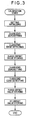
- Fig. 3 shows operational processes of the calibration.
- a rectangular reference to-be-measured object is placed on the stage 12. At this time, the reference to-be-measured object is placed such that sides of the reference to-be-measured object respectively are parallel to the directions X, Y, Z.
- the offset value in a previous measurement is deleted by operating the operation buttons 142 of the data processor 14 (setting initializing).
- the offset value in the direction X is measured and stored.
- the stage 12 is moved in the direction X such that a side of the optical image of the reference to-be-measured object formed on the screen 11 coincides with the Y-direction line of the cross hairs 111.
- the operation buttons 142 of the data processor 14 are operated, such that an X-direction position of the stage at this time is stored as zero (X-axis end zerosetting).
- the same side of the optical image of the reference to-be-measured object is detected by the edge detecting sensor 112 (X-axis end edge detecting), and an X-direction position (a) of the stage at this time is stored in the offset value storage 143 (X-axis offset value storing).
- the offset value in the direction Y is measured and stored.
- the stage 12 is moved in the direction Y such that a side of the optical image of the reference to-be-measured object formed on the screen 11 coincides with the X-direction line of the cross hairs 111.
- the operation buttons 142 of the data processor 14 are operated, such that a Y-direction position of the stage at this time is stored as zero (Y-axis end zerosetting).
- the same side of the optical image of the reference to-be-measured object is detected by the edge detecting sensor 112 (Y-axis end edge detecting), and a Y-direction position (b) of the stage at this time is stored in the offset value storage 143 (Y-axis offset value storing).
- the offset value (a, b) is stored (XY offset value storing).
- the offset value may be directly input to the data processor 14 by operating the operation buttons 142 and stored in the offset value storage 143.
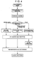
- Fig. 4 shows measurement processes.
- the operation buttons 142 of the data processor 14 are operated, such that measurement items such as a dimension and a profile are selected (measurement item selecting).
- the to-be-measured object is placed on the stage 12 and the stage 12 is moved such that the measurement edge of the optical image of the to-be-measured object formed on the screen 11 is moved to be close to the intersecting point of the cross hairs 111 or the edge detecting sensor 112 (to-be-measured object moving).
- the correction data calculator 144 receives measurement data of the stage 12 position at this time from the three linear encoders 121, 122, 123 via the connection cable 124 (XY counter value inputting), and stores and outputs the measurement data as a measurement value (measurement value determining).
- the edge detecting sensor 112 detects the measurement edge.
- the correction data calculator 144 receives the measurement data of the stage 12 position at the time when the measurement edge is detected from the three linear encoders 121, 122, 123 via the connection cable 124 (XY counter value inputting), subtracts the offset value stored in the offset value storage 143 from the measurement data (offset correcting) and stores and outputs the subtracted result as a measurement value (measurement value determining).
- a measurement with the edge detecting sensor 112 without offset correction may be designated at the time of the measurement item selection (edge detecting only).
- the XY counter value input is performed similarly as described above, no offset correction is performed and the measurement value is determined.
- the projector 13 may be moved while the stage 12 is fixed in the optical measuring machine 1.
- the body 10 may house the data processor 14 inside.
- the stand 145 may not be provided.
Landscapes
- Physics & Mathematics (AREA)
- General Physics & Mathematics (AREA)
- Length Measuring Devices By Optical Means (AREA)
- Image Processing (AREA)
Abstract
Description
- The present invention relates to an optical measuring machine having an optical system that forms on a screen an optical image of a to-be-measured object placed on a stage.
- There has been known an optical measuring machine that irradiates illumination light to a to-be-measured object placed on a stage, magnifies and forms an optical image on a screen from light transmitted or reflected from the to-be-measured object, and measures a dimension and a profile of the to-be-measured object from the optical image magnified and formed on the screen.
- In an optical measuring machine having a two-axis linear encoder on the stage, a measurement edge of the optical image of the to-be-measured object formed on the screen is matched to a reference point on the screen so as to read a two-dimensional coordinate of the stage at that time, and the dimension and the profile of the to-be-measured object is measured.
- By using an edge detecting sensor provided on the screen for detecting a passage of the measurement edge of the optical image and a data processor for storing the two-dimensional coordinate of the stage when the measurement edge passes by the edge detecting sensor, the passage of the measurement edge can be automatically detected and the two-dimensional coordinate of the stage at that time can be read. Since the edge detecting sensor detects the measurement edge, the measurement data can be prevented from varying among operators depending on a sense of the operator.
- There have been a variety of suggestions made from various viewpoints for the optical measuring machine having the edge detecting sensor. For instance,
JP-A-3-35106 - However, the optical measuring machine, in which the edge detecting sensor detects the passage of the measurement edge, may not be able to detect the measurement edge using the edge detecting sensor when the measurement edge is unclear or when a reflection measurement is performed.
- Although, even in such cases, a measurement can be performed by visually matching the measurement edge of the optical image to the reference point on the screen so as to designate the measurement edge as described above, the following problem may occur.
- The edge detecting sensor is generally provided at a position different from the reference point on the screen because the edge detecting sensor blocks the reference point from being visually observed when the edge detecting sensor is provided at the same position as the reference point. In this arrangement, an inconsistency may arise between visual-check measurement data and edge-detecting-sensor measurement data, the inconsistency corresponding to a distance between the reference point on the screen and the edge detecting sensor.
- Accordingly, when a plurality of measurement edges are measured so as to obtain the dimension and the profile of the to-be-measured object, the whole measurement needs to be performed either by visual check or the edge detecting sensor, and it has not been possible to perform both a visual-check measurement and an edge-detecting-sensor measurement in one measurement.
- An object of the present invention is to provide an optical measuring machine having an edge detecting sensor that can perform both a visual-check measurement and an edge-detecting-sensor measurement in one measurement.
- An optical measuring machine according to an aspect of the present invention includes: a screen having a reference line; a movable stage; an optical system forming on the screen an optical image of a to-be-measured object placed on the stage; an edge detecting sensor detecting a passage of a measurement edge of the optical image at an arbitrary position on the screen; an offset value storage storing a distance between the reference line and the edge detecting sensor as an offset value; and a correction data calculator using the offset value and correcting measurement data measured with the reference line and the edge detecting sensor.
- According to the aspect of the present invention, the optical measuring machine includes: the offset value storage that stores the distance between the reference line and the edge detecting sensor as the offset value; and the correction data calculator that uses the offset value and corrects the measurement data measured with the reference line and the edge detecting sensor. Accordingly, consistency between the visual-check measurement data and the edge-detecting-sensor measurement data is obtained.
- Specifically, although an inconsistency corresponding to the distance between the reference line on the screen and the edge detecting sensor arises between the visual-check measurement data and the edge-detecting-sensor measurement data, the offset value storage stores the distance between the reference point and the edge detecting sensor as the offset value in advance while the correction data calculator reads the offset value from the offset value storage and subtracts the offset value from the visual-check measurement data or the edge-detecting-sensor measurement data. With this arrangement, the inconsistency between the measurement data is resolved and the consistency between the measurement data can be obtained.
- Thus, the optical measuring machine having the edge detecting sensor can perform both a visual-check measurement and an edge-detecting-sensor measurement in one measurement.
- According to the aspect of the present invention, it is preferable that, in the optical measuring machine, the reference line is provided by cross hairs formed of two straight lines orthogonally crossing with each other, and the offset value is stored as two-dimensional information of two directions along the two straight lines of the cross hairs.
- According to the arrangement, in a two-dimensional measurement of a general XY coordinate, the inconsistency between the visual-check measurement data and the edge-detecting-sensor measurement data can be corrected and the consistency between the measurement data can be obtained. With this arrangement, it is possible to perform both a visual-check measurement and an edge-detecting-sensor measurement in one measurement.
- According to the aspect of the present invention, it is preferable that the optical measuring machine further includes a measuring method designator that designates which is used, the reference line or the edge detecting sensor, for a measurement.
- According to the arrangement, since whether to use the reference line or the edge detecting sensor for the measurement is designated so as to perform the measurement, an operator can determine whether to visually measure or to measure with the edge detecting sensor depending on a situation of each measurement edge.
-
- Fig. 1 is a perspective view showing an optical measuring machine according to an embodiment;
- Fig. 2 is an illustration schematically showing an arrangement of a data processor according to the embodiment;
- Fig. 3 is a diagram showing operational processes of a calibration according to the embodiment; and
- Fig. 4 is a diagram showing measurement processes using the optical measuring machine according to the embodiment.
- Embodiments of an optical measuring machine according to the present invention will be described below with reference to drawings.
- Fig. 1 is a perspective view showing an
optical measuring machine 1 according to an embodiment. - As shown in Fig. 1, the
optical measuring machine 1 includes: abody 10; ascreen 11; astage 12 on which a to-be-measured object is placed; aprojector 13 having an optical system that irradiates light to the to-be-measured object and forms an optical image on thescreen 11 based on the light; and adata processor 14. - The
body 10 is provided by: abase 101 having thestage 12; atrunk portion 102 mounted on an end of an upper surface of thebase 101; thescreen 11 provided on a front upper portion of thetrunk portion 102; and ahead 103 having theprojector 13. - The
screen 11 is provided on a front surface of thehead 103 of thebody 10 and includes:cross hairs 111 as a reference line for a visual-check measurement; and anedge detecting sensor 112. - The
cross hairs 111 are formed of two straight lines orthogonally crossing with each other at the center of thecircular screen 11. - The columnar
edge detecting sensor 112 housing an optical sensor detects a passage of a measurement edge of the optical image of the to-be-measured object formed on thescreen 11, the edge detecting sensor detecting the passage at any arbitrary point on thescreen 11.. Theedge detecting sensor 112 is fixed vertically to thescreen 11 with one end abutting on thescreen 11 while the other end being connected to thedata processor 14 via aconnection cable 115. - The
edge detecting sensor 112 is provided at a position different from an intersecting point of thecross hairs 111. When theedge detecting sensor 112 is provided at the intersecting point of thecross hairs 111, theedge detecting sensor 112 blocks the intersecting point of thecross hairs 111 from being visually observed. - The
stage 12 is provided on an upper surface of thebase 101 of thebody 10 so as to be movable in mutually orthogonal directions X, Y, Z, and houses threelinear encoders stage 12 in the directions. The threelinear encoders data processor 14 via aconnection cable 124. - Note that an anteroposterior direction, a horizontal direction and a vertical direction in Fig. 1 respectively correspond to the direction Y, the direction X and the direction Z. On the
screen 11, a horizontal direction corresponds to the direction X while a vertical direction corresponds to the direction Y. - The
projector 13 is provided on a lower surface of thehead 103 of thebody 10 and includes anoptical system 131. Theoptical system 131 irradiates light from a lower side of thestage 12 to the to-be-measured object placed on thestage 12 and forms the optical image of the to-be-measured object on thescreen 11 based on the light transmitted therethrough. - The
data processor 14 includes adisplay 141 andoperation buttons 142. Thedisplay 141 displays measurement-concerning data such as a measurement result and an offset value. Theoperation buttons 142 as a measurement method designator are operated so as to determine whether to use thecross hairs 111 or theedge detecting sensor 112 for a measurement. Incidentally, theoperation buttons 142 are not limited to the above use but may be used for other measurement operations. As described above, thedata processor 14 is connected to theedge detecting sensor 112 via theconnection cable 115 while being connected to the threelinear encoders connection cable 124. Thecode 145 represents a stand on which thedata processor 14 is placed. - Fig. 2 is an illustration schematically showing an arrangement of the
data processor 14. Thedata processor 14 includes anoffset value storage 143 and acorrection data calculator 144. Theoffset value storage 143 stores a distance between the intersecting point of thecross hairs 111 and theedge detecting sensor 112 as an offset value. The offset value is stored as two-dimensional information of the directions X and Y along thecross hairs 111. Thecorrection data calculator 144 uses the offset value stored in theoffset value storage 142 so as to correct measurement data measured with thecross hairs 111 and theedge detecting sensor 112. - Measuring operations using the
optical measuring machine 1 will be described below, in which the measurement edge is designated based on detection results both by a visual check and theedge detecting sensor 112 so as to measure the dimension and the profile of the to-be-measured object. - Before starting to measure, a calibration, i.e., storage of the offset value is performed. Fig. 3 shows operational processes of the calibration.
- A rectangular reference to-be-measured object is placed on the
stage 12. At this time, the reference to-be-measured object is placed such that sides of the reference to-be-measured object respectively are parallel to the directions X, Y, Z. The offset value in a previous measurement is deleted by operating theoperation buttons 142 of the data processor 14 (setting initializing). - Next, the offset value in the direction X is measured and stored.
- The
stage 12 is moved in the direction X such that a side of the optical image of the reference to-be-measured object formed on thescreen 11 coincides with the Y-direction line of thecross hairs 111. In this state, theoperation buttons 142 of thedata processor 14 are operated, such that an X-direction position of the stage at this time is stored as zero (X-axis end zerosetting). - Next, the same side of the optical image of the reference to-be-measured object is detected by the edge detecting sensor 112 (X-axis end edge detecting), and an X-direction position (a) of the stage at this time is stored in the offset value storage 143 (X-axis offset value storing).
- Next, the offset value in the direction Y is measured and stored.
- The
stage 12 is moved in the direction Y such that a side of the optical image of the reference to-be-measured object formed on thescreen 11 coincides with the X-direction line of thecross hairs 111. In this state, theoperation buttons 142 of thedata processor 14 are operated, such that a Y-direction position of the stage at this time is stored as zero (Y-axis end zerosetting). - Next, the same side of the optical image of the reference to-be-measured object is detected by the edge detecting sensor 112 (Y-axis end edge detecting), and a Y-direction position (b) of the stage at this time is stored in the offset value storage 143 (Y-axis offset value storing).
- Following the above processes, the offset value (a, b) is stored (XY offset value storing). Incidentally, instead of following the above described processes, the offset value may be directly input to the
data processor 14 by operating theoperation buttons 142 and stored in the offsetvalue storage 143. - Fig. 4 shows measurement processes.
- First of all, the
operation buttons 142 of thedata processor 14 are operated, such that measurement items such as a dimension and a profile are selected (measurement item selecting). - The to-be-measured object is placed on the
stage 12 and thestage 12 is moved such that the measurement edge of the optical image of the to-be-measured object formed on thescreen 11 is moved to be close to the intersecting point of thecross hairs 111 or the edge detecting sensor 112 (to-be-measured object moving). - Whether with the
cross hairs 111 or theedge detecting sensor 112 the measurement is performed is designated by operating the operation buttons 142 (measurement method selecting). - When the
cross hairs 111 is used (no edge detecting), thecorrection data calculator 144 receives measurement data of thestage 12 position at this time from the threelinear encoders - When the
edge detecting sensor 112 is used (edge detecting with correction), theedge detecting sensor 112 detects the measurement edge. Thecorrection data calculator 144 receives the measurement data of thestage 12 position at the time when the measurement edge is detected from the threelinear encoders value storage 143 from the measurement data (offset correcting) and stores and outputs the subtracted result as a measurement value (measurement value determining). - When the whole measurement is performed by the
edge detecting sensor 112, a measurement with theedge detecting sensor 112 without offset correction may be designated at the time of the measurement item selection (edge detecting only). In the above case, although the XY counter value input is performed similarly as described above, no offset correction is performed and the measurement value is determined. - According to the present embodiment, the following advantages are obtained.
- (1) The
data processor 14 includes: the offsetvalue storage 143 that stores the distance between thecross hairs 111 and theedge detecting sensor 112 as the offset value; and thecorrection data calculator 144 that uses the offset value and corrects the measurement data measured with thecross hairs 111 and theedge detecting sensor 112. Accordingly, consistency can be obtained between the visual-check measurement data and the edge-detecting-sensor-112 measurement data. In short, it is possible to perform both a visual-check measurement and an edge-detecting-sensor-112 measurement in one measurement. - (2) Since whether to use the
cross hairs 111 or theedge detecting sensor 112 for the measurement can be designated, a measurer can determine whether to visually measure or to measure with theedge detecting sensor 112 depending on a situation. - (3) Since the offset value can be directly input into the
data processor 14 and stored in the offsetvalue storage 143, the calibration can be omitted, thereby shorting the measurement time. For instance, when a measurement accuracy is not required, an approximate position of theedge detecting sensor 112, which is measured with a scale, may be used as the offset value, thereby simplifying the measurement. - (4) When the whole measurement is performed by the
edge detecting sensor 112, a measurement with theedge detecting sensor 112 without offset correction may be designated at the time of the measurement item selection. Accordingly, a measurement can be performed similarly as in a conventional optical measuring machine. - Note that the present invention is not limited to the above embodiment, but includes other arrangements and the like as long as objects of the present invention can be achieved, and the following modifications may be included in the present invention.
- (i) In the above-described embodiment, the process to designate the measuring method per measurement is shown, but the present invention is not limited thereto. For instance, when no measuring method is designated, a measurement may be automatically performed in accordance with the same measuring method as a previous measurement. Such an arrangement can omit the process to designate the measuring method each time when the measurement is performed in accordance with the same method several times, thereby shortening the measurement time.
- (ii) Although, in the calibration according to the above embodiment, the zerosetting process is visually performed and the detecting process of the reference to-be-measured object is subsequently performed by the
edge detecting sensor 112, the processes may be performed in the other way around. Specifically, after the zerosetting process is performed by theedge detecting sensor 112, the detecting process of the reference work may be visually performed. In the measurement performed in this manner, the offset value is subtracted from the measurement data obtained with thecross hairs 111 so as to be used as the measurement value and the measurement data obtained with theedge detecting sensor 112 is used as the measurement value as it is. - (iii) The
optical measuring machine 1 is not limited to the profile and arrangement disclosed in the above embodiment. - Although the above embodiment uses, for example, the optical measuring
machine 1 in which thestage 12 is moved, theprojector 13 may be moved while thestage 12 is fixed in the optical measuringmachine 1. - In addition, although the
data processor 14 is separated from thebody 10 of the optical measuringmachine 1 in the above embodiment, thebody 10 may house thedata processor 14 inside. In this case, there is an advantage, for example, that thestand 145 may not be provided.
Claims (3)
- An optical measuring machine, comprising:a screen having a reference line;a movable stage;an optical system forming on the screen an optical image of a to-be-measured object placed on the stage;an edge detecting sensor detecting a passage of a measurement edge of the optical image at an arbitrary position on the screen;an offset value storage storing a distance between the reference line and the edge detecting sensor as an offset value; anda correction data calculator using the offset value and correcting measurement data measured with the reference line and the edge detecting sensor.
- The optical measuring machine according to claim 1, wherein the reference line is provided by cross hairs formed of two straight lines orthogonally crossing with each other, and the offset value is stored as two-dimensional information of two directions along the two straight lines of the cross hairs.
- The optical measuring machine according to claim 1 or 2, wherein the optical measuring machine further comprises a measuring method designator that designates which is used, the reference line or the edge detecting sensor, for a measurement.
Applications Claiming Priority (1)
| Application Number | Priority Date | Filing Date | Title |
|---|---|---|---|
| JP2006205243A JP4778855B2 (en) | 2006-07-27 | 2006-07-27 | Optical measuring device |
Publications (2)
| Publication Number | Publication Date |
|---|---|
| EP1882894A1 true EP1882894A1 (en) | 2008-01-30 |
| EP1882894B1 EP1882894B1 (en) | 2009-02-04 |
Family
ID=38370432
Family Applications (1)
| Application Number | Title | Priority Date | Filing Date |
|---|---|---|---|
| EP07014692A Active EP1882894B1 (en) | 2006-07-27 | 2007-07-26 | Optical measuring machine |
Country Status (5)
| Country | Link |
|---|---|
| US (1) | US7646492B2 (en) |
| EP (1) | EP1882894B1 (en) |
| JP (1) | JP4778855B2 (en) |
| CN (1) | CN101113891B (en) |
| DE (1) | DE602007000517D1 (en) |
Families Citing this family (4)
| Publication number | Priority date | Publication date | Assignee | Title |
|---|---|---|---|---|
| US7777962B2 (en) * | 2008-05-30 | 2010-08-17 | The Invention Science Fund I, Llc | Negatively-refractive focusing and sensing apparatus, methods, and systems |
| KR101158323B1 (en) * | 2010-10-14 | 2012-06-26 | 주식회사 고영테크놀러지 | Method for inspecting substrate |
| EP3488179A4 (en) * | 2016-07-20 | 2020-08-12 | Arun Kumar | DIGITAL FAST MULTI-PURPOSE PROFILE PROJECTOR |
| CN107084697B (en) * | 2017-04-20 | 2019-06-28 | 武汉新芯集成电路制造有限公司 | Memory Cell Distortion Measurement Method |
Citations (2)
| Publication number | Priority date | Publication date | Assignee | Title |
|---|---|---|---|---|
| JPH0335106A (en) * | 1989-06-30 | 1991-02-15 | Y S Denshi Kogyo Kk | Optical measuring instrument |
| US5590060A (en) * | 1992-03-20 | 1996-12-31 | Metronics, Inc. | Apparatus and method for an object measurement system |
Family Cites Families (2)
| Publication number | Priority date | Publication date | Assignee | Title |
|---|---|---|---|---|
| JP2678127B2 (en) | 1992-07-15 | 1997-11-17 | 株式会社ミツトヨ | Optical measuring device |
| JP4652717B2 (en) * | 2004-04-26 | 2011-03-16 | 株式会社ミツトヨ | Image processing apparatus and method, and program |
-
2006
- 2006-07-27 JP JP2006205243A patent/JP4778855B2/en active Active
-
2007
- 2007-07-25 US US11/878,543 patent/US7646492B2/en active Active
- 2007-07-26 CN CN2007101381354A patent/CN101113891B/en active Active
- 2007-07-26 EP EP07014692A patent/EP1882894B1/en active Active
- 2007-07-26 DE DE602007000517T patent/DE602007000517D1/en active Active
Patent Citations (2)
| Publication number | Priority date | Publication date | Assignee | Title |
|---|---|---|---|---|
| JPH0335106A (en) * | 1989-06-30 | 1991-02-15 | Y S Denshi Kogyo Kk | Optical measuring instrument |
| US5590060A (en) * | 1992-03-20 | 1996-12-31 | Metronics, Inc. | Apparatus and method for an object measurement system |
Also Published As
| Publication number | Publication date |
|---|---|
| US20080024791A1 (en) | 2008-01-31 |
| CN101113891A (en) | 2008-01-30 |
| JP2008032496A (en) | 2008-02-14 |
| US7646492B2 (en) | 2010-01-12 |
| JP4778855B2 (en) | 2011-09-21 |
| CN101113891B (en) | 2011-06-29 |
| EP1882894B1 (en) | 2009-02-04 |
| DE602007000517D1 (en) | 2009-03-19 |
Similar Documents
| Publication | Publication Date | Title |
|---|---|---|
| CN112683215B (en) | Method for providing information about a sensor chain of a coordinate measuring machine, coordinate measuring machine | |
| US10234260B2 (en) | Method to control a drive mechanism of an automated machine having a camera | |
| US20100232681A1 (en) | Three-dimensional vision sensor | |
| EP1315056A2 (en) | Simulation apparatus for working machine | |
| CN112505663A (en) | Calibration method for multi-line laser radar and camera combined calibration | |
| CN109813283B (en) | Handheld device, method for image-based measurement using a handheld device | |
| EP1882894B1 (en) | Optical measuring machine | |
| US11257205B2 (en) | Image measuring method and apparatus | |
| CN107907055B (en) | Pattern projection module, three-dimensional information acquisition system, processing device and measuring method | |
| CN109425320A (en) | The control method of surface texture measuring device | |
| CN113778241B (en) | Mouse device and method for calibrating its sensitivity | |
| US7330307B2 (en) | Stage apparatus | |
| JP2005121370A (en) | Surface shape measuring apparatus and surface shape measuring method | |
| JP2017110909A (en) | Crack width measuring device | |
| KR100704831B1 (en) | Real-time inspection guidance system and method using 3D scanner | |
| KR101888363B1 (en) | Sensor Test Bed, Object Sensing Device, Object Sensing Method for Sensing the 3D Shape of The Object | |
| KR200223563Y1 (en) | Gap Measurer | |
| JP2020016570A (en) | Three-dimensional measuring device and method for aligning position of three-dimensional model | |
| US20190113336A1 (en) | Multi-Directional Triangulation Measuring System with Method | |
| JP7057732B2 (en) | 3D measuring device | |
| JP4533050B2 (en) | Surface shape measuring apparatus and surface shape measuring method | |
| CN100417914C (en) | Image processing device and image processing method | |
| JP3905783B2 (en) | Measurement data capture device | |
| CN108489390A (en) | A kind of 3D optical dimensions detector and optical dimensions detecting system | |
| JPH1082630A (en) | Length-measuring apparatus and method for confirming accuracy of length-measuring apparatus |
Legal Events
| Date | Code | Title | Description |
|---|---|---|---|
| PUAI | Public reference made under article 153(3) epc to a published international application that has entered the european phase |
Free format text: ORIGINAL CODE: 0009012 |
|
| AK | Designated contracting states |
Kind code of ref document: A1 Designated state(s): AT BE BG CH CY CZ DE DK EE ES FI FR GB GR HU IE IS IT LI LT LU LV MC MT NL PL PT RO SE SI SK TR |
|
| AX | Request for extension of the european patent |
Extension state: AL BA HR MK YU |
|
| 17P | Request for examination filed |
Effective date: 20080319 |
|
| 17Q | First examination report despatched |
Effective date: 20080428 |
|
| GRAP | Despatch of communication of intention to grant a patent |
Free format text: ORIGINAL CODE: EPIDOSNIGR1 |
|
| AKX | Designation fees paid |
Designated state(s): DE FR GB |
|
| GRAS | Grant fee paid |
Free format text: ORIGINAL CODE: EPIDOSNIGR3 |
|
| GRAA | (expected) grant |
Free format text: ORIGINAL CODE: 0009210 |
|
| AK | Designated contracting states |
Kind code of ref document: B1 Designated state(s): DE FR GB |
|
| REG | Reference to a national code |
Ref country code: GB Ref legal event code: FG4D |
|
| REF | Corresponds to: |
Ref document number: 602007000517 Country of ref document: DE Date of ref document: 20090319 Kind code of ref document: P |
|
| PLBE | No opposition filed within time limit |
Free format text: ORIGINAL CODE: 0009261 |
|
| STAA | Information on the status of an ep patent application or granted ep patent |
Free format text: STATUS: NO OPPOSITION FILED WITHIN TIME LIMIT |
|
| 26N | No opposition filed |
Effective date: 20091105 |
|
| REG | Reference to a national code |
Ref country code: FR Ref legal event code: PLFP Year of fee payment: 10 |
|
| REG | Reference to a national code |
Ref country code: FR Ref legal event code: PLFP Year of fee payment: 11 |
|
| REG | Reference to a national code |
Ref country code: FR Ref legal event code: PLFP Year of fee payment: 12 |
|
| PGFP | Annual fee paid to national office [announced via postgrant information from national office to epo] |
Ref country code: DE Payment date: 20250722 Year of fee payment: 19 |
|
| PGFP | Annual fee paid to national office [announced via postgrant information from national office to epo] |
Ref country code: GB Payment date: 20250722 Year of fee payment: 19 |
|
| PGFP | Annual fee paid to national office [announced via postgrant information from national office to epo] |
Ref country code: FR Payment date: 20250724 Year of fee payment: 19 |