EP1882854A2 - Apparatus for assembling rotary machines - Google Patents
Apparatus for assembling rotary machines Download PDFInfo
- Publication number
- EP1882854A2 EP1882854A2 EP07111892A EP07111892A EP1882854A2 EP 1882854 A2 EP1882854 A2 EP 1882854A2 EP 07111892 A EP07111892 A EP 07111892A EP 07111892 A EP07111892 A EP 07111892A EP 1882854 A2 EP1882854 A2 EP 1882854A2
- Authority
- EP
- European Patent Office
- Prior art keywords
- blade
- hub
- wind turbine
- coupled
- wall
- Prior art date
- Legal status (The legal status is an assumption and is not a legal conclusion. Google has not performed a legal analysis and makes no representation as to the accuracy of the status listed.)
- Granted
Links
- 238000000034 method Methods 0.000 description 27
- 238000005266 casting Methods 0.000 description 10
- 238000005242 forging Methods 0.000 description 10
- 239000011295 pitch Substances 0.000 description 10
- 230000014759 maintenance of location Effects 0.000 description 8
- 238000007789 sealing Methods 0.000 description 5
- 230000000903 blocking effect Effects 0.000 description 4
- 238000012546 transfer Methods 0.000 description 4
- 230000000712 assembly Effects 0.000 description 3
- 238000000429 assembly Methods 0.000 description 3
- 230000003247 decreasing effect Effects 0.000 description 3
- 239000000463 material Substances 0.000 description 3
- 238000009826 distribution Methods 0.000 description 2
- 238000012423 maintenance Methods 0.000 description 2
- 230000013011 mating Effects 0.000 description 2
- 238000012544 monitoring process Methods 0.000 description 2
- 229910000838 Al alloy Inorganic materials 0.000 description 1
- 230000033228 biological regulation Effects 0.000 description 1
- 230000005540 biological transmission Effects 0.000 description 1
- 239000000919 ceramic Substances 0.000 description 1
- 238000006243 chemical reaction Methods 0.000 description 1
- 239000002131 composite material Substances 0.000 description 1
- 238000010276 construction Methods 0.000 description 1
- 238000001816 cooling Methods 0.000 description 1
- 230000000694 effects Effects 0.000 description 1
- 239000003562 lightweight material Substances 0.000 description 1
- 230000001050 lubricating effect Effects 0.000 description 1
- 238000012986 modification Methods 0.000 description 1
- 230000004048 modification Effects 0.000 description 1
- 230000007935 neutral effect Effects 0.000 description 1
- 230000003014 reinforcing effect Effects 0.000 description 1
- 230000001360 synchronised effect Effects 0.000 description 1
- 239000013598 vector Substances 0.000 description 1
- 238000003466 welding Methods 0.000 description 1
Images


Classifications
-
- F—MECHANICAL ENGINEERING; LIGHTING; HEATING; WEAPONS; BLASTING
- F03—MACHINES OR ENGINES FOR LIQUIDS; WIND, SPRING, OR WEIGHT MOTORS; PRODUCING MECHANICAL POWER OR A REACTIVE PROPULSIVE THRUST, NOT OTHERWISE PROVIDED FOR
- F03D—WIND MOTORS
- F03D1/00—Wind motors with rotation axis substantially parallel to the air flow entering the rotor
- F03D1/06—Rotors
- F03D1/065—Rotors characterised by their construction elements
- F03D1/0691—Rotors characterised by their construction elements of the hub
-
- F—MECHANICAL ENGINEERING; LIGHTING; HEATING; WEAPONS; BLASTING
- F03—MACHINES OR ENGINES FOR LIQUIDS; WIND, SPRING, OR WEIGHT MOTORS; PRODUCING MECHANICAL POWER OR A REACTIVE PROPULSIVE THRUST, NOT OTHERWISE PROVIDED FOR
- F03D—WIND MOTORS
- F03D1/00—Wind motors with rotation axis substantially parallel to the air flow entering the rotor
- F03D1/06—Rotors
- F03D1/065—Rotors characterised by their construction elements
- F03D1/0658—Arrangements for fixing wind-engaging parts to a hub
-
- F—MECHANICAL ENGINEERING; LIGHTING; HEATING; WEAPONS; BLASTING
- F03—MACHINES OR ENGINES FOR LIQUIDS; WIND, SPRING, OR WEIGHT MOTORS; PRODUCING MECHANICAL POWER OR A REACTIVE PROPULSIVE THRUST, NOT OTHERWISE PROVIDED FOR
- F03D—WIND MOTORS
- F03D13/00—Assembly, mounting or commissioning of wind motors; Arrangements specially adapted for transporting wind motor components
- F03D13/20—Arrangements for mounting or supporting wind motors; Masts or towers for wind motors
-
- F—MECHANICAL ENGINEERING; LIGHTING; HEATING; WEAPONS; BLASTING
- F03—MACHINES OR ENGINES FOR LIQUIDS; WIND, SPRING, OR WEIGHT MOTORS; PRODUCING MECHANICAL POWER OR A REACTIVE PROPULSIVE THRUST, NOT OTHERWISE PROVIDED FOR
- F03D—WIND MOTORS
- F03D15/00—Transmission of mechanical power
- F03D15/05—Transmission of mechanical power using hollow exhausting blades
-
- F—MECHANICAL ENGINEERING; LIGHTING; HEATING; WEAPONS; BLASTING
- F03—MACHINES OR ENGINES FOR LIQUIDS; WIND, SPRING, OR WEIGHT MOTORS; PRODUCING MECHANICAL POWER OR A REACTIVE PROPULSIVE THRUST, NOT OTHERWISE PROVIDED FOR
- F03D—WIND MOTORS
- F03D80/00—Details, components or accessories not provided for in groups F03D1/00 - F03D17/00
-
- F—MECHANICAL ENGINEERING; LIGHTING; HEATING; WEAPONS; BLASTING
- F03—MACHINES OR ENGINES FOR LIQUIDS; WIND, SPRING, OR WEIGHT MOTORS; PRODUCING MECHANICAL POWER OR A REACTIVE PROPULSIVE THRUST, NOT OTHERWISE PROVIDED FOR
- F03D—WIND MOTORS
- F03D80/00—Details, components or accessories not provided for in groups F03D1/00 - F03D17/00
- F03D80/70—Bearing or lubricating arrangements
-
- F—MECHANICAL ENGINEERING; LIGHTING; HEATING; WEAPONS; BLASTING
- F05—INDEXING SCHEMES RELATING TO ENGINES OR PUMPS IN VARIOUS SUBCLASSES OF CLASSES F01-F04
- F05B—INDEXING SCHEME RELATING TO WIND, SPRING, WEIGHT, INERTIA OR LIKE MOTORS, TO MACHINES OR ENGINES FOR LIQUIDS COVERED BY SUBCLASSES F03B, F03D AND F03G
- F05B2240/00—Components
- F05B2240/90—Mounting on supporting structures or systems
-
- F—MECHANICAL ENGINEERING; LIGHTING; HEATING; WEAPONS; BLASTING
- F05—INDEXING SCHEMES RELATING TO ENGINES OR PUMPS IN VARIOUS SUBCLASSES OF CLASSES F01-F04
- F05B—INDEXING SCHEME RELATING TO WIND, SPRING, WEIGHT, INERTIA OR LIKE MOTORS, TO MACHINES OR ENGINES FOR LIQUIDS COVERED BY SUBCLASSES F03B, F03D AND F03G
- F05B2250/00—Geometry
- F05B2250/10—Geometry two-dimensional
- F05B2250/11—Geometry two-dimensional triangular
-
- Y—GENERAL TAGGING OF NEW TECHNOLOGICAL DEVELOPMENTS; GENERAL TAGGING OF CROSS-SECTIONAL TECHNOLOGIES SPANNING OVER SEVERAL SECTIONS OF THE IPC; TECHNICAL SUBJECTS COVERED BY FORMER USPC CROSS-REFERENCE ART COLLECTIONS [XRACs] AND DIGESTS
- Y02—TECHNOLOGIES OR APPLICATIONS FOR MITIGATION OR ADAPTATION AGAINST CLIMATE CHANGE
- Y02E—REDUCTION OF GREENHOUSE GAS [GHG] EMISSIONS, RELATED TO ENERGY GENERATION, TRANSMISSION OR DISTRIBUTION
- Y02E10/00—Energy generation through renewable energy sources
- Y02E10/70—Wind energy
- Y02E10/72—Wind turbines with rotation axis in wind direction
-
- Y—GENERAL TAGGING OF NEW TECHNOLOGICAL DEVELOPMENTS; GENERAL TAGGING OF CROSS-SECTIONAL TECHNOLOGIES SPANNING OVER SEVERAL SECTIONS OF THE IPC; TECHNICAL SUBJECTS COVERED BY FORMER USPC CROSS-REFERENCE ART COLLECTIONS [XRACs] AND DIGESTS
- Y02—TECHNOLOGIES OR APPLICATIONS FOR MITIGATION OR ADAPTATION AGAINST CLIMATE CHANGE
- Y02E—REDUCTION OF GREENHOUSE GAS [GHG] EMISSIONS, RELATED TO ENERGY GENERATION, TRANSMISSION OR DISTRIBUTION
- Y02E10/00—Energy generation through renewable energy sources
- Y02E10/70—Wind energy
- Y02E10/728—Onshore wind turbines
Definitions
- This invention relates generally to rotary machines and more particularly, to apparatus for assembling wind turbine hub assemblies.
- a wind turbine generator includes a turbine that has a rotatable hub assembly having multiple blades.
- the hub assembly is coupled to a rotor.
- the blades transform mechanical wind energy into a mechanical rotational torque that drives one or more generators via the rotor.
- the generators are generally, but not always, rotationally coupled to the rotor through a gearbox.
- the gearbox steps up the inherently low rotational speed of the rotor for the generator to efficiently convert the rotational mechanical energy to electrical energy, which is fed into a utility grid.
- Gearless direct drive wind turbine generators also exist.
- the rotor, generator, gearbox and other components are typically mounted within a housing, or nacelle, that is positioned on top of a base that may be a truss or tubular tower.
- Some known hub assembly configurations introduce substantial weight at the top of the wind turbine tower in order to facilitate effective energy transfer from the wind to the blades and, subsequently, to the rotor.
- the associated load support features of the nacelles that support the hub assemblies further facilitate increased weight at the top of the wind tower.
- the increased weight of the wind turbine generators may increase capital and operational costs.
- a wind turbine generator in one aspect according to the present invention, includes at least one blade and a hub assembly.
- the hub assembly includes at least one substantially cylindrical wall defining a substantially annular hub cavity.
- the assembly also includes at least one substantially triangular frame inserted into the hub cavity and is fixedly coupled to the cylindrical wall.
- the assembly further includes at least one blade attachment apparatus having at least one blade support sleeve fixedly coupled to at least a portion of the cylindrical wall. The sleeve is configured to receive at least a portion of the wind turbine blade.
- a hub assembly for a rotary machine includes at least one substantially cylindrical wall defining a substantially annular hub cavity.
- the assembly also includes at least one substantially triangular frame inserted into the hub cavity and is fixedly coupled to the cylindrical wall.
- a blade attachment apparatus for a wind turbine has a hub assembly.
- the apparatus includes at least one blade support sleeve fixedly coupled to at least a portion of the hub assembly.
- the sleeve is configured to receive at least a portion of a wind turbine blade.
- FIG 1 is an exploded schematic view of an exemplary wind turbine generator 100.
- wind turbine generator 100 is a horizontal axis wind turbine.
- wind turbine 100 may be a vertical axis wind turbine.
- wind turbine 100 may be a 1.5 Megawatt (MW)-series or a 2.5 MW-series wind turbine generator commercially available from General Electric Company, Schenectady, New York.
- wind turbine 100 may be any wind turbine generator in which the invention described herein may be embodied.
- Wind turbine 100 includes a mounting fixture 102 extending from either a tower or a supporting surface (neither shown in Figure 1). In the event that a tower is used, a height of the tower is selected based upon factors and conditions known in the art.
- Wind turbine 100 also includes a hub assembly 104, a shell 106, a cover assembly 108, and a main frame 110.
- Shell 106 is fixedly coupled to main frame 110 and cover assembly 108 is removably coupled to main frame 110.
- Hub assembly 104 is removably coupled to shell 106.
- Hub assembly 104, shell 106, cover assembly 108 and main frame 110 cooperate to facilitate load support and load distribution within wind turbine 100.
- Cover assembly 108 includes an integrated cooling system (not shown in Figure 1) that facilitates maintaining wind turbine 100 components within hub 104, shell 106 and cover 108 within predetermined operational temperature parameters.
- Hub 104 includes a plurality of blade support sleeves 112 disposed substantially equidistantly circumferentially about hub 104.
- wind turbine 100 has three blade support sleeves 112.
- rotor 108 may have more or less than three blade support tubes 112.
- sleeves 112 are substantially cylindrical tubes 112.
- sleeves 112 may be of any configuration that facilitates predetermined operational parameters of wind turbine 100.
- Hub 104 also includes a nose element 114 that facilitates an aerodynamic efficiency of wind turbine 100.
- Hub 104 is coupled to shell 106 via a hub face plate 116 and a frame mating surface 118.
- a substantially annular interior surface portion 117 of shell 106 and plate 116 at least partially define a cavity 120 when plate 116 and surface 118 are coupled.
- a main bearing 122 and a support member 123 are positioned within cavity 120.
- Bearing 122 facilitates radial support and alignment of hub 104 and includes a radially outermost surface 121.
- Member 123 facilitates support and alignment of bearing 122 within wind turbine 100 and includes a radially inner surface 119 and a radially outer surface 125.
- Surface 119 is coupled to surface 121 via a friction fit prior to bearing 122 and member 123 positioning within cavity 120.
- Surface 125 is coupled to surface 117 via a friction fit upon positioning bearing 122 and member 123 within cavity 120.
- Wind turbine generator 100 further includes a generator 124 that facilitates converting wind energy as captured by hub assembly 104 and generating electrical energy for subsequent transmission to an electrical distribution system (not shown in Figure 1).
- a rotor (not shown in Figure 1) is rotatably coupled to hub 104 and extends to generator 124. The rotor is coupled to a rotatable exciter (not shown in Figure 1) that is disposed within generator 124.
- generator 124 is a direct-drive generator, i.e., hub 104 drives generator 124 exciter directly via the rotor.
- a gearbox (not shown in Figure 1) is positioned between hub assembly 104 and generator 124 within shell 106 and is used to step up a rotational speed generated by hub 104 to a generator 124 exciter speed that is substantially synchronous.
- a hub-to-gearbox/hub-to-direct-drive generator connector 126 is also disposed within cavity 120.
- Connector 126 facilitates radial support and alignment of the rotor from hub 104 to generator 124 (in the exemplary embodiment) or to a gear box (in an alternative embodiment).
- Connector 126 includes a plurality of passages 128 that facilitate personnel and material transport between hub 104 and the portions of wind turbine 100 defined within shell 106 and cover 108.
- Blade support tubes 112 are each configured to receive a blade (not shown in Figure 1).
- hub 104 receives three rotor blades.
- hub 104 receives any number of blades that facilitates attaining predetermined operational parameters of wind turbine 100.
- the blades are positioned about hub 104 to facilitate rotating hub 104 to transfer kinetic energy from the wind into usable mechanical energy via the rotor, and subsequently, electrical energy within generator 124.
- the blades have a length between 50 meters (m) (164 feet (ft)) and 100 m (328 ft).
- blades 112 may have any length that attains predetermined operational parameters of wind turbine 100.
- Wind turbine 100 also includes a yaw adjustment mechanism 130 that may be used to rotate wind turbine 100 on an axis (not shown in Figure 1) to control the perspective of wind turbine 100 with respect to the direction of the wind.
- Mechanism 130 is coupled to main frame 110 and to a yaw bearing 132 and at least one yaw drive gear (not shown in Figure 1) wherein bearing 132 and the drive gear are coupled to mounting fixture 102.
- Bearing 132 facilitates support and alignment of wind turbine 100 during yaw adjustment operations.
- one or more microcontrollers in a control system are used for overall system monitoring and control including pitch and yaw adjustments, rotor speed regulation, yaw brake application, and fault monitoring.
- a control system not shown in Figure 1
- distributed or centralized control architectures are used in alternate embodiments of wind turbine 100.
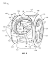
- FIG 2 is a cross-sectional schematic view of exemplary hub assembly 104 that may be used with the wind turbine generator shown in Figure 1.
- Figure 3 is a cross-sectional schematic side view of hub assembly 104 and
- Figure 4 is a skewed cross-sectional schematic side view of hub assembly 104.
- Hub 104 includes a substantially cylindrical outer wall 140 fixedly coupled to nose element 114. Nose 114 and wall 140 define a hub cavity 142.
- Hub 104 also includes a plurality of polygonal blade flange plates 144 fixedly coupled to wall 140. Plates 144 are configured within cavity 142 in a substantially triangular configuration wherein at least one of plates 144 is substantially parallel to main frame 110.
- plates 144 and wall 140 are formed individually by methods that include, but are not limited to, forging and casting. Moreover, in the exemplary embodiment, plates 144 are welded to wall 140 within cavity 142. Alternatively, plates 144 are coupled to wall 140 via methods that include, but are not limited to, retention hardware, such as bolts and nuts, and sealing methods and apparatus known in the art. Further, alternatively, hub 104 is formed with plates 144 integral to wall 140 via methods that include, but are not limited to, casting and forging.
- Hub 104 further includes a substantially circular front flange plate 146 that is positioned in a forward portion, i.e., a nose 114 end, of hub 104 opposite to substantially circular rear flange plate 116 that is positioned in an aft portion, i.e., a generator 124 end,, of hub 104.
- Plate 146 defines a substantially circular passage 148 that facilitates personnel and material transit into an interior of nose 114.
- plate 146 is formed via methods that include, but are not limited to, casting and forging and is welded to wall 140.
- plate 146 is coupled to wall 140 via methods that include, but are not limited to, retention hardware, such as bolts and nuts, and sealing methods and apparatus known in the art.
- plate 146 is formed integrally with hub 104 via methods that include, but are not limited to, casting and forging.
- Hub face plate 116 is substantially annular and includes a passage 150 configured to receive substantially annular support plate 123 and connector 126.
- plate 116 is formed via methods that include, but are not limited to, casting and forging and is welded to wall 140.
- plate 116 is coupled to wall 140 via methods that include, but are not limited to, retention hardware, such as bolts and nuts, and sealing methods and apparatus known in the art.
- plate 116 is formed integrally with hub 104 via methods that include, but are not limited to, casting and forging.
- Hub 104 further includes a plurality of support plates 152.
- six plates 152 are positioned within cavity 142, i.e., three of plates 152 are positioned on the nose 114 end of hub 104 and three plates 152 are positioned on the generator 124 end of hub 104.
- Each of plates 152 is polygonal with at least four circumferential sides. With respect to the three plates 152 that are positioned on the nose 114 end of hub 104, one end of each plate 152 is coupled to a radially inner portion of plate 146. An opposing side of each plate 152 is coupled to wall 140.
- plate 152 The remaining two sides of plate 152 are coupled to each of two adjacent flange plates 144 such that a cavity 154 is defined by each of plates 152, wall 140, plates 144 and plate 146.
- one end of plates 152 are coupled to a radially inner portion of rear flange plate 116.
- An opposing side of each plate 152 is coupled to wall 140.
- the remaining two sides of plate 152 are coupled to each of two adjacent flange plates 144 such that a cavity 154 is defined by each of plates 152, wall 140, plates 144 and plate 116.
- plates 152 are formed via methods that include, but are not limited to, casting and forging and are welded to wall 140, flange plates 144, and/or plates 146 and 116.
- plates 152 are coupled to wall 140, flange plates 144, and/or plates 146 and 116 via methods that include, but are not limited to, retention hardware, such as bolts and nuts, and sealing methods and apparatus known in the art.
- plates 152 are formed integrally with hub 104 via methods that include, but are not limited to, casting and forging.
- support tubes 112 are formed via methods that include, but are not limited to, casting and forging and are welded to wall 140 and flange plates 144.
- support tubes 112 are coupled to wall 140 via methods that include, but are not limited to, retention hardware, such as bolts and nuts, and sealing methods and apparatus known in the art.
- tubes 112 are formed integrally with hub 104 via methods that include, but are not limited to, casting and forging.
- Support tubes 112 facilitate support and alignment of the blades.
- Support tubes 112, wall 140 and plates 144 define a plurality of cavities 156.
- Such methods and apparatus for assembling hub assembly 104 as described above facilitates increased load bearing and load transfer characteristics of hub 104 due to the reinforcing characteristics of tubes 112, wall 140, and plates 144, 146, 116, and 152.
- lightweight materials that include, but are not limited to, aluminum alloys and ceramic composites, are used to fabricate many of the hub 104 components as described herein. Therefore, such methods and apparatus for assembling hub assembly 104 as described above, including defining cavities 154 and 156, facilitate decreasing the weight of hub 104.
- Each of blade flange plates 144 define a substantially annular passage 158 that is configured to receive a blade pitch bearing 160 and a blade (not shown).
- Support tubes 112 facilitate support and alignment of the blades within passage 158.
- At least one pitch drive mechanism 162 modulates the pitch of the blades along a pitch axis (not shown).
- each blade receives one mechanism 162.
- the blades may deflect and/or rotate from a neutral, or non-deflected, position to a deflected position and facilitate increasing or decreasing the blades rotational speed by adjusting the surface area of the blades exposed to the wind force vectors.
- the pitches of the blades are controlled individually. However, in some embodiments the pitch of two or more blades may be controlled as a group.
- Bearing 160 facilitates pitch movements of the blades as well as supports and aligns the blades within passage 158.
- Bearings 160 include a stationary, radially inner hub portion 164 and a rotating, radially outer blade portion 166.
- portion 164 is coupled to flange plate 144 via methods that include, but are not limited to, retention hardware such as bolts and nuts (not shown).
- portion 164 is coupled to flange plate 144 via methods that include, but are not limited to, welding.
- Portion 166 is slidingly coupled to portion 164 and support tube 112 and the blade is coupled to portion 166 via methods that include, but are not limited to , retention hardware such as bolts and nuts.
- Each of bearings 160 also include a bearing blocking device (not shown) that is positioned within a bearing blocking device passage 167. The blocking device facilitates maintaining the associated blade substantially stationary during activities that include, but are not limited to, maintenance outages.
- a plurality of hardware passages 168 is formed within flange plates 144, inner portion 164 and outer portion 166 and configured to permit such access. Moreover, positioning bearing 160 within passage 158 to permit access from within hub cavity 142 facilitates a reduction of potential for release of lubricating materials external to hub 104.
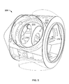
- FIG 5 is a skewed cross-sectional schematic side view of an alternative hub assembly 204 that may be used with wind turbine generator 100 (shown in Figure 1).
- Assembly 204 is substantially similar to assembly 104 (shown in Figures 1, 2, 3, and 4) with the exception that a plurality of alternative polygonal blade flange plates 244 are fixedly coupled to an alternative substantially cylindrical wall 240.
- plates 244 are extended to form two blade flange plate passages 258 for each blade (not shown).
- the blades are configured with two extended prongs (not shown) that are configured to be received within passages 258.
- Further alternative embodiments include any number of passages 258 that facilitate operation of wind turbine 100 as described herein.
- the methods and apparatus for a wind turbine generator hub assembly described herein facilitate operation of a wind turbine generator. More specifically, the wind turbine generator hub assembly as described above facilitates an efficient and effective energy conversion scheme. Also, the robust hub assembly facilitates increased load bearing and load transfer characteristics. Moreover, the hub assembly facilitates decreasing the weight of the wind turbine generator. Such hub assembly also facilitates wind turbine generator reliability, and reduced maintenance costs and wind turbine generator outages.
- PARTS LIST 100 wind turbine 102 mounting fixture 104 hub assembly 106 shell 108 cover assembly 110 main frame 112 blade support tube 114 nose 116 hub face plate 117 interior surface portion 118 frame mating surface 119 inner surface 120 cavity 121 outermost surface 122 main bearing 123 support member 124 generator 125 outer surface 126 connector 128 passages 130 yaw adjustment mechanism 132 yaw bearing 140 cylindrical outer wall 142 hub cavity 144 flange plates 146 front flange plate 148 circular passage 150 passage 152 support plates 154 cavity 156 cavities 158 annular passage 160 blade pitch bearing 162 pitch drive mechanism 164 inner hub portion 166 outer blade portion 167 bearing blocking device passage 168 hardware passages 204 hub assembly 240 cylindrical wall 244 polygonal blade flange plates 258 passages
Landscapes
- Engineering & Computer Science (AREA)
- Life Sciences & Earth Sciences (AREA)
- Sustainable Development (AREA)
- Sustainable Energy (AREA)
- Chemical & Material Sciences (AREA)
- Combustion & Propulsion (AREA)
- Mechanical Engineering (AREA)
- General Engineering & Computer Science (AREA)
- Wind Motors (AREA)
Abstract
Description
- This invention relates generally to rotary machines and more particularly, to apparatus for assembling wind turbine hub assemblies.
- Generally, a wind turbine generator includes a turbine that has a rotatable hub assembly having multiple blades. The hub assembly is coupled to a rotor. The blades transform mechanical wind energy into a mechanical rotational torque that drives one or more generators via the rotor. The generators are generally, but not always, rotationally coupled to the rotor through a gearbox. The gearbox steps up the inherently low rotational speed of the rotor for the generator to efficiently convert the rotational mechanical energy to electrical energy, which is fed into a utility grid. Gearless direct drive wind turbine generators also exist. The rotor, generator, gearbox and other components are typically mounted within a housing, or nacelle, that is positioned on top of a base that may be a truss or tubular tower.
- Some known hub assembly configurations introduce substantial weight at the top of the wind turbine tower in order to facilitate effective energy transfer from the wind to the blades and, subsequently, to the rotor. The associated load support features of the nacelles that support the hub assemblies further facilitate increased weight at the top of the wind tower. However, the increased weight of the wind turbine generators may increase capital and operational costs.
- In one aspect according to the present invention, a wind turbine generator is provided. The wind turbine generator includes at least one blade and a hub assembly. The hub assembly includes at least one substantially cylindrical wall defining a substantially annular hub cavity. The assembly also includes at least one substantially triangular frame inserted into the hub cavity and is fixedly coupled to the cylindrical wall. The assembly further includes at least one blade attachment apparatus having at least one blade support sleeve fixedly coupled to at least a portion of the cylindrical wall. The sleeve is configured to receive at least a portion of the wind turbine blade.
- In another aspect, a hub assembly for a rotary machine is provided. The assembly includes at least one substantially cylindrical wall defining a substantially annular hub cavity. The assembly also includes at least one substantially triangular frame inserted into the hub cavity and is fixedly coupled to the cylindrical wall.
- In a further aspect, a blade attachment apparatus for a wind turbine is provided. The wind turbine has a hub assembly. The apparatus includes at least one blade support sleeve fixedly coupled to at least a portion of the hub assembly. The sleeve is configured to receive at least a portion of a wind turbine blade.
- Various aspects and embodiments of the present invention will now be described in connection with the accompanying drawings, in which:
- Figure 1 is an exploded schematic view of an exemplary wind turbine generator;
- Figure 2 is a cross-sectional schematic axial view of an exemplary hub assembly that may be used with the wind turbine generator shown in Figure 1;
- Figure 3 is a cross-sectional schematic side view of the hub assembly shown in Figure 2;
- Figure 4 is a skewed cross-sectional schematic side view of the hub assembly shown in Figure 3; and
- Figure 5 is a skewed cross-sectional schematic side view of an alternative hub assembly that may be used with the wind turbine generator shown in Figure 1.
- Figure 1 is an exploded schematic view of an exemplary
wind turbine generator 100. In the exemplary embodiment,wind turbine generator 100 is a horizontal axis wind turbine. Alternatively,wind turbine 100 may be a vertical axis wind turbine. Also, alternatively,wind turbine 100 may be a 1.5 Megawatt (MW)-series or a 2.5 MW-series wind turbine generator commercially available from General Electric Company, Schenectady, New York. Further, alternatively,wind turbine 100 may be any wind turbine generator in which the invention described herein may be embodied.Wind turbine 100 includes amounting fixture 102 extending from either a tower or a supporting surface (neither shown in Figure 1). In the event that a tower is used, a height of the tower is selected based upon factors and conditions known in the art.Wind turbine 100 also includes ahub assembly 104, ashell 106, acover assembly 108, and amain frame 110.Shell 106 is fixedly coupled tomain frame 110 andcover assembly 108 is removably coupled tomain frame 110.Hub assembly 104 is removably coupled toshell 106.Hub assembly 104,shell 106,cover assembly 108 andmain frame 110 cooperate to facilitate load support and load distribution withinwind turbine 100.Cover assembly 108 includes an integrated cooling system (not shown in Figure 1) that facilitates maintainingwind turbine 100 components withinhub 104,shell 106 andcover 108 within predetermined operational temperature parameters. -
Hub 104 includes a plurality ofblade support sleeves 112 disposed substantially equidistantly circumferentially abouthub 104. In the exemplary embodiment,wind turbine 100 has threeblade support sleeves 112. Alternatively,rotor 108 may have more or less than threeblade support tubes 112. Also, in the exemplary embodiment,sleeves 112 are substantiallycylindrical tubes 112. Alternatively,sleeves 112 may be of any configuration that facilitates predetermined operational parameters ofwind turbine 100. Hub 104 also includes anose element 114 that facilitates an aerodynamic efficiency ofwind turbine 100. Hub 104 is coupled toshell 106 via ahub face plate 116 and aframe mating surface 118. A substantially annularinterior surface portion 117 ofshell 106 andplate 116 at least partially define acavity 120 whenplate 116 andsurface 118 are coupled. A main bearing 122 and asupport member 123 are positioned withincavity 120.Bearing 122 facilitates radial support and alignment ofhub 104 and includes a radiallyoutermost surface 121.Member 123 facilitates support and alignment of bearing 122 withinwind turbine 100 and includes a radiallyinner surface 119 and a radiallyouter surface 125.Surface 119 is coupled tosurface 121 via a friction fit prior to bearing 122 andmember 123 positioning withincavity 120.Surface 125 is coupled tosurface 117 via a friction fit upon positioning bearing 122 andmember 123 withincavity 120. -
Wind turbine generator 100 further includes agenerator 124 that facilitates converting wind energy as captured byhub assembly 104 and generating electrical energy for subsequent transmission to an electrical distribution system (not shown in Figure 1). A rotor (not shown in Figure 1) is rotatably coupled tohub 104 and extends togenerator 124. The rotor is coupled to a rotatable exciter (not shown in Figure 1) that is disposed withingenerator 124. In the exemplary embodiment,generator 124 is a direct-drive generator, i.e.,hub 104drives generator 124 exciter directly via the rotor. Alternatively, a gearbox (not shown in Figure 1) is positioned betweenhub assembly 104 andgenerator 124 withinshell 106 and is used to step up a rotational speed generated byhub 104 to agenerator 124 exciter speed that is substantially synchronous. - In the exemplary embodiment, a hub-to-gearbox/hub-to-direct-
drive generator connector 126 is also disposed withincavity 120.Connector 126 facilitates radial support and alignment of the rotor fromhub 104 to generator 124 (in the exemplary embodiment) or to a gear box (in an alternative embodiment).Connector 126 includes a plurality ofpassages 128 that facilitate personnel and material transport betweenhub 104 and the portions ofwind turbine 100 defined withinshell 106 andcover 108. Some alternative embodiments ofwind turbine 100 excludeconnector 126. -
Blade support tubes 112 are each configured to receive a blade (not shown in Figure 1). In the exemplary embodiment,hub 104 receives three rotor blades. In an alternative embodiment,hub 104 receives any number of blades that facilitates attaining predetermined operational parameters ofwind turbine 100. The blades are positioned abouthub 104 to facilitaterotating hub 104 to transfer kinetic energy from the wind into usable mechanical energy via the rotor, and subsequently, electrical energy withingenerator 124. In the exemplary embodiment, the blades have a length between 50 meters (m) (164 feet (ft)) and 100 m (328 ft). Alternatively,blades 112 may have any length that attains predetermined operational parameters ofwind turbine 100. -
Wind turbine 100 also includes ayaw adjustment mechanism 130 that may be used to rotatewind turbine 100 on an axis (not shown in Figure 1) to control the perspective ofwind turbine 100 with respect to the direction of the wind.Mechanism 130 is coupled tomain frame 110 and to ayaw bearing 132 and at least one yaw drive gear (not shown in Figure 1) whereinbearing 132 and the drive gear are coupled to mountingfixture 102. Bearing 132 facilitates support and alignment ofwind turbine 100 during yaw adjustment operations. - In some configurations, one or more microcontrollers in a control system (not shown in Figure 1) are used for overall system monitoring and control including pitch and yaw adjustments, rotor speed regulation, yaw brake application, and fault monitoring. Alternatively, distributed or centralized control architectures are used in alternate embodiments of
wind turbine 100. - Figure 2 is a cross-sectional schematic view of
exemplary hub assembly 104 that may be used with the wind turbine generator shown in Figure 1. Figure 3 is a cross-sectional schematic side view ofhub assembly 104 and Figure 4 is a skewed cross-sectional schematic side view ofhub assembly 104.Hub 104 includes a substantially cylindricalouter wall 140 fixedly coupled tonose element 114.Nose 114 andwall 140 define ahub cavity 142.Hub 104 also includes a plurality of polygonalblade flange plates 144 fixedly coupled towall 140.Plates 144 are configured withincavity 142 in a substantially triangular configuration wherein at least one ofplates 144 is substantially parallel tomain frame 110. In the exemplary embodiment,plates 144 andwall 140 are formed individually by methods that include, but are not limited to, forging and casting. Moreover, in the exemplary embodiment,plates 144 are welded to wall 140 withincavity 142. Alternatively,plates 144 are coupled towall 140 via methods that include, but are not limited to, retention hardware, such as bolts and nuts, and sealing methods and apparatus known in the art. Further, alternatively,hub 104 is formed withplates 144 integral to wall 140 via methods that include, but are not limited to, casting and forging.Hub 104 further includes a substantially circularfront flange plate 146 that is positioned in a forward portion, i.e., anose 114 end, ofhub 104 opposite to substantially circularrear flange plate 116 that is positioned in an aft portion, i.e., agenerator 124 end,, ofhub 104.Plate 146 defines a substantiallycircular passage 148 that facilitates personnel and material transit into an interior ofnose 114. In the exemplary embodiment,plate 146 is formed via methods that include, but are not limited to, casting and forging and is welded towall 140. Alternatively,plate 146 is coupled towall 140 via methods that include, but are not limited to, retention hardware, such as bolts and nuts, and sealing methods and apparatus known in the art. Further, alternatively,plate 146 is formed integrally withhub 104 via methods that include, but are not limited to, casting and forging.Hub face plate 116 is substantially annular and includes apassage 150 configured to receive substantiallyannular support plate 123 andconnector 126. Some alternative embodiments ofwind turbine 100 excludeconnector 126. In the exemplary embodiment,plate 116 is formed via methods that include, but are not limited to, casting and forging and is welded towall 140. Alternatively,plate 116 is coupled towall 140 via methods that include, but are not limited to, retention hardware, such as bolts and nuts, and sealing methods and apparatus known in the art. Further, alternatively,plate 116 is formed integrally withhub 104 via methods that include, but are not limited to, casting and forging. -
Hub 104 further includes a plurality ofsupport plates 152. In the exemplary embodiment, sixplates 152 are positioned withincavity 142, i.e., three ofplates 152 are positioned on thenose 114 end ofhub 104 and threeplates 152 are positioned on thegenerator 124 end ofhub 104. Each ofplates 152 is polygonal with at least four circumferential sides. With respect to the threeplates 152 that are positioned on thenose 114 end ofhub 104, one end of eachplate 152 is coupled to a radially inner portion ofplate 146. An opposing side of eachplate 152 is coupled towall 140. The remaining two sides ofplate 152 are coupled to each of twoadjacent flange plates 144 such that acavity 154 is defined by each ofplates 152,wall 140,plates 144 andplate 146. Similarly, for the threeplates 152 positioned on thegenerator 124 end ofhub 104, one end ofplates 152 are coupled to a radially inner portion ofrear flange plate 116. An opposing side of eachplate 152 is coupled towall 140. The remaining two sides ofplate 152 are coupled to each of twoadjacent flange plates 144 such that acavity 154 is defined by each ofplates 152,wall 140,plates 144 andplate 116. In the exemplary embodiment,plates 152 are formed via methods that include, but are not limited to, casting and forging and are welded towall 140,flange plates 144, and/orplates plates 152 are coupled towall 140,flange plates 144, and/orplates plates 152 are formed integrally withhub 104 via methods that include, but are not limited to, casting and forging. - In the exemplary embodiment,
support tubes 112 are formed via methods that include, but are not limited to, casting and forging and are welded to wall 140 andflange plates 144. Alternatively,support tubes 112 are coupled towall 140 via methods that include, but are not limited to, retention hardware, such as bolts and nuts, and sealing methods and apparatus known in the art. Further, alternatively,tubes 112 are formed integrally withhub 104 via methods that include, but are not limited to, casting and forging.Support tubes 112 facilitate support and alignment of the blades.Support tubes 112,wall 140 andplates 144 define a plurality ofcavities 156. - Such methods and apparatus for assembling
hub assembly 104 as described above, sometimes referred to as double-wall construction, facilitates increased load bearing and load transfer characteristics ofhub 104 due to the reinforcing characteristics oftubes 112,wall 140, andplates hub 104 components as described herein. Therefore, such methods and apparatus for assemblinghub assembly 104 as described above, including definingcavities hub 104. - Each of
blade flange plates 144 define a substantiallyannular passage 158 that is configured to receive ablade pitch bearing 160 and a blade (not shown).Support tubes 112 facilitate support and alignment of the blades withinpassage 158. At least onepitch drive mechanism 162 modulates the pitch of the blades along a pitch axis (not shown). Generally, each blade receives onemechanism 162. As such, the blades may deflect and/or rotate from a neutral, or non-deflected, position to a deflected position and facilitate increasing or decreasing the blades rotational speed by adjusting the surface area of the blades exposed to the wind force vectors. In the exemplary embodiment, the pitches of the blades are controlled individually. However, in some embodiments the pitch of two or more blades may be controlled as a group. Bearing 160 facilitates pitch movements of the blades as well as supports and aligns the blades withinpassage 158. -
Bearings 160 include a stationary, radiallyinner hub portion 164 and a rotating, radiallyouter blade portion 166. In the exemplary embodiment,portion 164 is coupled toflange plate 144 via methods that include, but are not limited to, retention hardware such as bolts and nuts (not shown). Alternatively,portion 164 is coupled toflange plate 144 via methods that include, but are not limited to, welding.Portion 166 is slidingly coupled toportion 164 andsupport tube 112 and the blade is coupled toportion 166 via methods that include, but are not limited to , retention hardware such as bolts and nuts. Each ofbearings 160 also include a bearing blocking device (not shown) that is positioned within a bearingblocking device passage 167. The blocking device facilitates maintaining the associated blade substantially stationary during activities that include, but are not limited to, maintenance outages. - In order to facilitate access to the retention hardware from within
hub cavity 142, a plurality ofhardware passages 168 is formed withinflange plates 144,inner portion 164 andouter portion 166 and configured to permit such access. Moreover, positioning bearing 160 withinpassage 158 to permit access from withinhub cavity 142 facilitates a reduction of potential for release of lubricating materials external tohub 104. - Figure 5 is a skewed cross-sectional schematic side view of an
alternative hub assembly 204 that may be used with wind turbine generator 100 (shown in Figure 1).Assembly 204 is substantially similar to assembly 104 (shown in Figures 1, 2, 3, and 4) with the exception that a plurality of alternative polygonalblade flange plates 244 are fixedly coupled to an alternative substantiallycylindrical wall 240. In the alternative embodiment,plates 244 are extended to form two bladeflange plate passages 258 for each blade (not shown). Also, in the alternative embodiment, the blades are configured with two extended prongs (not shown) that are configured to be received withinpassages 258. Further alternative embodiments include any number ofpassages 258 that facilitate operation ofwind turbine 100 as described herein. - The methods and apparatus for a wind turbine generator hub assembly described herein facilitate operation of a wind turbine generator. More specifically, the wind turbine generator hub assembly as described above facilitates an efficient and effective energy conversion scheme. Also, the robust hub assembly facilitates increased load bearing and load transfer characteristics. Moreover, the hub assembly facilitates decreasing the weight of the wind turbine generator. Such hub assembly also facilitates wind turbine generator reliability, and reduced maintenance costs and wind turbine generator outages.
- Exemplary embodiments of wind turbine hub assemblies as associated with wind turbine generators are described above in detail. The methods, apparatus and systems are not limited to the specific embodiments described herein nor to the specific illustrated wind turbine generators.
- While the invention has been described in terms of various specific embodiments, those skilled in the art will recognize that the invention can be practiced with modification within the spirit and scope of the claims.
PARTS LIST 100 wind turbine 102 mounting fixture 104 hub assembly 106 shell 108 cover assembly 110 main frame 112 blade support tube 114 nose 116 hub face plate 117 interior surface portion 118 frame mating surface 119 inner surface 120 cavity 121 outermost surface 122 main bearing 123 support member 124 generator 125 outer surface 126 connector 128 passages 130 yaw adjustment mechanism 132 yaw bearing 140 cylindrical outer wall 142 hub cavity 144 flange plates 146 front flange plate 148 circular passage 150 passage 152 support plates 154 cavity 156 cavities 158 annular passage 160 blade pitch bearing 162 pitch drive mechanism 164 inner hub portion 166 outer blade portion 167 bearing blocking device passage 168 hardware passages 204 hub assembly 240 cylindrical wall 244 polygonal blade flange plates 258 passages
Claims (10)
- A wind turbine generator (124) comprising:at least one blade; anda hub assembly (104) comprising:at least one substantially cylindrical wall (140) defining a substantially annular hub cavity (142);at least one substantially triangular frame inserted into said hub cavity and fixedly coupled to said cylindrical wall; andat least one blade attachment apparatus comprising at least one blade support sleeve (112) fixedly coupled to at least a portion of said wall, said sleeve configured to receive at least a portion of said wind turbine blade.
- A wind turbine generator (124) in accordance with Claim 1 wherein said
substantially triangular frame comprises a plurality of structural members defining at least one passage (148, 150) and at least one cavity (154, 156), said passage is configured to receive at least one blade pitch bearing (160), said structural members comprise:at least one blade flange plate (144) coupled to at least a portion of said wall;at least one front flange plate (146) coupled to at least a portion of said wall;at least one rear flange plate coupled to at least a portion of said wall; andat least one support plate (152) coupled to at least a portion of at least one of said wall, said flange plate, said front flange plate, said rear flange plate. - A wind turbine generator (124) in accordance with Claim 2 wherein said blade pitch bearing (160) comprises a blade portion (166) and a hub portion (164), said hub portion slidingly engaged with said blade portion.
- A wind turbine generator (124) in accordance with Claim 3 wherein said blade portion (166) is positioned radially outboard of said hub portion (164) and said hub portion is substantially stationary and fixedly coupled to at least a portion of at least one hub assembly structural member (123).
- A wind turbine generator (124) in accordance with Claim 3 or Claim 4 wherein said wherein said blade portion (166) is slidingly engaged with at least a portion of said support sleeve (112), is rotatably coupled to a blade pitch drive mechanism (162), and is configured to receive said blade.
- A wind turbine generator (124) in accordance with any preceding Claim wherein said support sleeve (112) comprises at least one substantially cylindrical member coupled to and extending radially outward from at least a portion of said cylindrical wall (140).
- A hub assembly (104) for a rotary machine comprising:at least one substantially cylindrical wall (140) defining a substantially annular hub cavity (120); andat least one substantially triangular frame inserted into said hub cavity (142) and fixedly coupled to said cylindrical wall.
- A hub assembly (104) in accordance with Claim 7 wherein said substantially triangular frame comprises a plurality of structural members defining at least one passage (148) and at least one cavity (154).
- A hub assembly (104) in accordance with Claim 8 wherein said structural members comprise:at least one blade flange plate (144) coupled to at least a portion of said wall;at least one front flange plate (146) coupled to at least a portion of said wall;at least one rear flange plate coupled to at least a portion of said wall; andat least one support plate (152) coupled to at least a portion of at least one of said wall, said flange plate, said front flange plate, said rear flange plate.
- A blade attachment apparatus for a wind turbine (100), the wind turbine having a hub assembly (104), said apparatus comprising at least one blade support sleeve (112) fixedly coupled to at least a portion of the hub assembly, said sleeve configured to receive at least a portion of a wind turbine blade.
Applications Claiming Priority (1)
| Application Number | Priority Date | Filing Date | Title |
|---|---|---|---|
| US11/456,616 US7614850B2 (en) | 2006-07-11 | 2006-07-11 | Apparatus for assembling rotary machines |
Publications (3)
| Publication Number | Publication Date |
|---|---|
| EP1882854A2 true EP1882854A2 (en) | 2008-01-30 |
| EP1882854A3 EP1882854A3 (en) | 2015-02-25 |
| EP1882854B1 EP1882854B1 (en) | 2017-09-27 |
Family
ID=38787556
Family Applications (1)
| Application Number | Title | Priority Date | Filing Date |
|---|---|---|---|
| EP07111892.1A Ceased EP1882854B1 (en) | 2006-07-11 | 2007-07-06 | Apparatus for assembling rotary machines |
Country Status (3)
| Country | Link |
|---|---|
| US (1) | US7614850B2 (en) |
| EP (1) | EP1882854B1 (en) |
| CN (1) | CN101105173B (en) |
Cited By (8)
| Publication number | Priority date | Publication date | Assignee | Title |
|---|---|---|---|---|
| WO2011076796A3 (en) * | 2009-12-21 | 2011-12-29 | Vestas Wind Systems A/S | A reinforced hub for a wind turbine |
| WO2011076795A3 (en) * | 2009-12-21 | 2011-12-29 | Vestas Wind Systems A/S | A hub for a wind turbine and a method for fabricating the hub |
| EP2412970A1 (en) | 2010-07-26 | 2012-02-01 | Alstom Wind, S.L.U. | Nacelle for a wind turbine |
| WO2012034564A1 (en) * | 2010-09-15 | 2012-03-22 | Vestas Wind Systems A/S | An apparatus for and method of mounting wind turbine blades on a wind turbine tower |
| EP1944508A3 (en) * | 2007-01-10 | 2012-12-05 | General Electric Company | Wind turbine compising a nacelle |
| US8480369B2 (en) | 2008-12-19 | 2013-07-09 | Mitsubishi Heavy Industries, Ltd. | Rotor head of wind power generator and wind power generator |
| EP2314865A4 (en) * | 2008-05-29 | 2014-03-19 | Acciona Windpower Sa | Wind generator comprising an improved housing |
| DE102015213660A1 (en) * | 2015-07-21 | 2017-01-26 | Voith Patent Gmbh | Hub of an axial turbine and method of manufacture |
Families Citing this family (33)
| Publication number | Priority date | Publication date | Assignee | Title |
|---|---|---|---|---|
| DE102006055091A1 (en) * | 2006-11-21 | 2008-05-29 | Repower Systems Ag | Bulkhead of a wind turbine |
| JP4972383B2 (en) * | 2006-11-22 | 2012-07-11 | 富士重工業株式会社 | Horizontal axis windmill hub |
| WO2008098574A1 (en) * | 2007-02-12 | 2008-08-21 | Vestas Wind Systems A/S | A wind turbine, a method for establishing at least one aperture in the spinner on the hub of a wind turbine rotor and use of a wind turbine |
| US8287238B2 (en) * | 2008-02-29 | 2012-10-16 | General Electric Company | Hub pitch gear repair method |
| GB2461285B (en) * | 2008-06-26 | 2012-07-25 | Converteam Technology Ltd | Vertical axis wind turbines |
| JP5566609B2 (en) * | 2009-01-05 | 2014-08-06 | 三菱重工業株式会社 | Wind power generator and control method for wind power generator |
| WO2010088181A2 (en) * | 2009-01-28 | 2010-08-05 | Cincinnati Machine, Llc | Machining center for a wind turbine hub |
| DE102009008437A1 (en) * | 2009-02-11 | 2010-08-12 | Vensys Energy Ag | Machine carrier for receiving a rotor / generator assembly of a gearless wind turbine |
| US8091199B2 (en) * | 2009-03-19 | 2012-01-10 | General Electric Company | Method to repair pitch control components |
| MX341495B (en) | 2010-01-14 | 2016-08-23 | Neptco Inc * | WIND TURBINE ROTOR BLADE COMPONENTS AND METHODS FOR THE MANUFACTURE OF THE SAME. |
| US10137542B2 (en) | 2010-01-14 | 2018-11-27 | Senvion Gmbh | Wind turbine rotor blade components and machine for making same |
| EP2550453B1 (en) * | 2010-03-22 | 2014-04-23 | Vestas Wind Systems A/S | A nacelle for a wind turbine, the nacelle comprising side units |
| US8016569B2 (en) * | 2010-06-09 | 2011-09-13 | General Electric Company | Configuration of a wind turbine nacelle for transportation |
| US8696314B2 (en) * | 2010-06-15 | 2014-04-15 | General Electric Company | Gear set, wind turbine incorporating such a gear set and method of servicing a wind turbine |
| DE102010043436A1 (en) | 2010-11-04 | 2012-05-10 | Aloys Wobben | door lock |
| WO2012130240A1 (en) * | 2011-03-30 | 2012-10-04 | Vestas Wind Systems A/S | A hub for a wind turbine |
| US9261072B2 (en) | 2011-05-11 | 2016-02-16 | Daniel E. Davis | Wind turbine elevator for hoisting a naecelle along a tower and pivoting the naecelle at a top of the tower |
| US20120025538A1 (en) * | 2011-06-20 | 2012-02-02 | Michael James Luneau | Unitary support frame for use in wind turbines and methods for fabricating same |
| US8246312B2 (en) | 2011-06-24 | 2012-08-21 | General Electric Company | Hub assembly for use with a wind turbine and method of making the same |
| DK2574781T3 (en) * | 2011-09-30 | 2014-08-11 | Alstom Renovables Espana Sl | wind turbine rotor |
| DK2623770T3 (en) * | 2012-02-02 | 2015-09-28 | Siemens Ag | Rotor hub for a wind turbine |
| US9115698B2 (en) * | 2012-03-06 | 2015-08-25 | General Electric Company | Wind turbine with access features for gaining access to the interior of a rotor hub |
| DK2685098T3 (en) * | 2012-07-10 | 2015-05-04 | Siemens Ag | Base frame structure for a wind turbine |
| US20140064971A1 (en) * | 2012-08-29 | 2014-03-06 | General Electric Company | Stiffener plate for a wind turbine |
| DE102013003634B4 (en) | 2013-03-05 | 2022-10-20 | Nordex Energy Se & Co. Kg | Wind turbine rotor blade with a blade connection area |
| US9140232B2 (en) | 2013-07-09 | 2015-09-22 | General Electric Company | Method for repairing a pitch system in a wind turbine |
| US10598159B2 (en) | 2016-05-06 | 2020-03-24 | General Electric Company | Wind turbine bearings |
| CN108953077B (en) * | 2018-07-26 | 2021-01-22 | 北京金风科创风电设备有限公司 | Lubricating system, lubricating method and wind generating set |
| EP3690232B1 (en) * | 2019-01-31 | 2023-01-04 | Siemens Gamesa Renewable Energy A/S | Hub for a wind turbine, wind turbine and method for up-grading a hub of a wind turbine |
| CN115053064B (en) | 2020-02-17 | 2025-08-08 | 维斯塔斯风力系统有限公司 | Nacelle for a wind turbine and method of manufacturing a wind turbine |
| US20220154687A1 (en) | 2020-11-13 | 2022-05-19 | Wobben Properties Gmbh | Rotor hub for a wind power installation, and corresponding rotor arrangement and wind power installation |
| CN113357090B (en) * | 2021-06-28 | 2023-04-07 | 新疆金风科技股份有限公司 | Cabin assembly and wind generating set |
| CN116221006B (en) * | 2023-03-23 | 2025-11-21 | 远景能源有限公司 | Split type wind driven generator hub |
Family Cites Families (22)
| Publication number | Priority date | Publication date | Assignee | Title |
|---|---|---|---|---|
| US2473899A (en) * | 1943-12-11 | 1949-06-21 | Curtiss Wright Corp | Articulated and universal joint for propellers and other mechanisms |
| US2645294A (en) * | 1948-10-07 | 1953-07-14 | Elwood M Douthett | Variable pitch propeller |
| US2765859A (en) * | 1954-09-15 | 1956-10-09 | Hartzell Propeller Fan Co | Fan |
| US4565929A (en) * | 1983-09-29 | 1986-01-21 | The Boeing Company | Wind powered system for generating electricity |
| US4557666A (en) * | 1983-09-29 | 1985-12-10 | The Boeing Company | Wind turbine rotor |
| US4915590A (en) * | 1987-08-24 | 1990-04-10 | Fayette Manufacturing Corporation | Wind turbine blade attachment methods |
| US5213470A (en) * | 1991-08-16 | 1993-05-25 | Robert E. Lundquist | Wind turbine |
| KR960007401B1 (en) * | 1994-06-27 | 1996-05-31 | 신찬 | Multi-unit rotor blade system integrated wind turbine |
| US6327957B1 (en) * | 1998-01-09 | 2001-12-11 | Wind Eagle Joint Venture | Wind-driven electric generator apparatus of the downwind type with flexible changeable-pitch blades |
| DE19916453A1 (en) * | 1999-04-12 | 2000-10-19 | Flender A F & Co | Wind turbine |
| NL1013807C2 (en) * | 1999-12-09 | 2001-07-05 | Aerpac Holding B V | Wind turbine rotor, as well as hub and extender therefor. |
| US6951443B1 (en) * | 2000-09-08 | 2005-10-04 | General Electric Company | Wind turbine ring/shroud drive system |
| SE521357C2 (en) * | 2001-03-30 | 2003-10-28 | Nordic Windpower Ab | Hub for a wind turbine in a wind turbine and a wind turbine with such a hub |
| DK174085B1 (en) * | 2001-04-02 | 2002-06-03 | Vestas Wind Sys As | Wind turbine with planetary gear |
| FR2827019B1 (en) * | 2001-07-06 | 2003-09-26 | Defontaine Sa | DEVICE FOR AUTOMATIC LUBRICATION OF BALL BEARINGS EQUIPPED IN PARTICULAR WITH WIND TURBINES |
| DE10224439C5 (en) * | 2002-06-01 | 2009-12-31 | Aloys Wobben | Method for assembly / disassembly of components of a wind turbine |
| DK175912B1 (en) * | 2002-12-20 | 2005-06-20 | Lm Glasfiber As | Process for operating a wind turbine |
| US7244102B2 (en) * | 2003-04-12 | 2007-07-17 | General Electric Company | Reinforced hub for the rotor of a wind energy turbine |
| DE102004023773B3 (en) * | 2004-05-11 | 2005-11-17 | Repower Systems Ag | Wind turbine |
| US7059822B2 (en) * | 2004-06-30 | 2006-06-13 | General Electrick Company | Methods and apparatus for measuring wind turbine blade deflection |
| US7381029B2 (en) * | 2004-09-30 | 2008-06-03 | General Electric Company | Multi-piece wind turbine rotor blades and wind turbines incorporating same |
| US7740450B2 (en) * | 2005-11-23 | 2010-06-22 | General Electric Company | Lightweight hub for rotors |
-
2006
- 2006-07-11 US US11/456,616 patent/US7614850B2/en not_active Expired - Fee Related
-
2007
- 2007-07-06 EP EP07111892.1A patent/EP1882854B1/en not_active Ceased
- 2007-07-11 CN CN2007101290923A patent/CN101105173B/en not_active Expired - Fee Related
Cited By (11)
| Publication number | Priority date | Publication date | Assignee | Title |
|---|---|---|---|---|
| EP1944508A3 (en) * | 2007-01-10 | 2012-12-05 | General Electric Company | Wind turbine compising a nacelle |
| EP2314865A4 (en) * | 2008-05-29 | 2014-03-19 | Acciona Windpower Sa | Wind generator comprising an improved housing |
| US8480369B2 (en) | 2008-12-19 | 2013-07-09 | Mitsubishi Heavy Industries, Ltd. | Rotor head of wind power generator and wind power generator |
| WO2011076796A3 (en) * | 2009-12-21 | 2011-12-29 | Vestas Wind Systems A/S | A reinforced hub for a wind turbine |
| WO2011076795A3 (en) * | 2009-12-21 | 2011-12-29 | Vestas Wind Systems A/S | A hub for a wind turbine and a method for fabricating the hub |
| EP3453871A1 (en) * | 2009-12-21 | 2019-03-13 | Vestas Wind Systems A/S | A hub for a wind turbine and a method for fabricating the hub |
| EP2412970A1 (en) | 2010-07-26 | 2012-02-01 | Alstom Wind, S.L.U. | Nacelle for a wind turbine |
| WO2012013636A1 (en) | 2010-07-26 | 2012-02-02 | Alstom Wind, S.L.U. | Nacelle for a wind turbine |
| WO2012034564A1 (en) * | 2010-09-15 | 2012-03-22 | Vestas Wind Systems A/S | An apparatus for and method of mounting wind turbine blades on a wind turbine tower |
| US9599093B2 (en) | 2010-09-15 | 2017-03-21 | Vestas Wind Systems A/S | Apparatus for and method of mounting wind turbine blades on a wind turbine tower |
| DE102015213660A1 (en) * | 2015-07-21 | 2017-01-26 | Voith Patent Gmbh | Hub of an axial turbine and method of manufacture |
Also Published As
| Publication number | Publication date |
|---|---|
| EP1882854A3 (en) | 2015-02-25 |
| US7614850B2 (en) | 2009-11-10 |
| EP1882854B1 (en) | 2017-09-27 |
| CN101105173B (en) | 2013-05-29 |
| US20080014088A1 (en) | 2008-01-17 |
| CN101105173A (en) | 2008-01-16 |
Similar Documents
| Publication | Publication Date | Title |
|---|---|---|
| EP1882854B1 (en) | Apparatus for assembling rotary machines | |
| US8556591B2 (en) | Systems and methods for assembling a rotor lock assembly for use in a wind turbine | |
| EP2143936B1 (en) | Wind turbine comprising a main bearing and method for replacement of the main bearing | |
| US7857599B2 (en) | Method and apparatus for forming wind turbine machines | |
| KR101723718B1 (en) | Wind turbine nacelle | |
| AU2009337789B2 (en) | Generator, nacelle, and mounting method of a nacelle of a wind energy converter | |
| EP1860322A2 (en) | WInd turbine generator and a semi-monocoque structure therefor | |
| CN207819572U (en) | Stator assembly of a generator for a wind turbine, generator and wind turbine for generating electricity | |
| CN102032113B (en) | Systems and methods for assembling a pitch control assembly for use in a wind turbine | |
| US20090250939A1 (en) | Wind-driven generation of power | |
| US8975770B2 (en) | Wind power turbine electric generator and wind power turbine equipped with an electric generator | |
| US20120181792A1 (en) | Wind turbine | |
| EP1944507A2 (en) | A wind turbine generator and a monocoque for rotary machines | |
| US8469664B2 (en) | Yaw bearing assembly and tower for wind turbine | |
| US12006910B2 (en) | Assemblies for wind turbines and methods | |
| KR20140108733A (en) | Wind turbine rotor | |
| KR20240054178A (en) | Drive train assemblies for wind turbines | |
| EP2975262B1 (en) | Wind power generation facility | |
| US10502195B2 (en) | Clamping apparatus for securing a main bearing of a wind turbine during an installation and/or repair procedure | |
| JP2021523322A (en) | Rotor bearing housing and wind turbine with rotor bearing housing | |
| US20190195197A1 (en) | Rotor arresting device for a wind turbine and method |
Legal Events
| Date | Code | Title | Description |
|---|---|---|---|
| PUAI | Public reference made under article 153(3) epc to a published international application that has entered the european phase |
Free format text: ORIGINAL CODE: 0009012 |
|
| AK | Designated contracting states |
Kind code of ref document: A2 Designated state(s): AT BE BG CH CY CZ DE DK EE ES FI FR GB GR HU IE IS IT LI LT LU LV MC MT NL PL PT RO SE SI SK TR |
|
| AX | Request for extension of the european patent |
Extension state: AL BA HR MK YU |
|
| PUAL | Search report despatched |
Free format text: ORIGINAL CODE: 0009013 |
|
| AK | Designated contracting states |
Kind code of ref document: A3 Designated state(s): AT BE BG CH CY CZ DE DK EE ES FI FR GB GR HU IE IS IT LI LT LU LV MC MT NL PL PT RO SE SI SK TR |
|
| AX | Request for extension of the european patent |
Extension state: AL BA HR MK RS |
|
| RIC1 | Information provided on ipc code assigned before grant |
Ipc: F03D 11/04 20060101ALI20150122BHEP Ipc: F03D 11/02 20060101ALI20150122BHEP Ipc: F03D 11/00 20060101AFI20150122BHEP Ipc: F03D 1/06 20060101ALI20150122BHEP |
|
| 17P | Request for examination filed |
Effective date: 20150825 |
|
| RBV | Designated contracting states (corrected) |
Designated state(s): AT BE BG CH CY CZ DE DK EE ES FI FR GB GR HU IE IS IT LI LT LU LV MC MT NL PL PT RO SE SI SK TR |
|
| AKX | Designation fees paid |
Designated state(s): DE DK ES |
|
| AXX | Extension fees paid |
Extension state: RS Extension state: AL Extension state: BA Extension state: HR Extension state: MK |
|
| 17Q | First examination report despatched |
Effective date: 20160510 |
|
| REG | Reference to a national code |
Ref country code: DE Ref legal event code: R079 Ref document number: 602007052466 Country of ref document: DE Free format text: PREVIOUS MAIN CLASS: F03D0011000000 Ipc: F03D0080000000 |
|
| RIC1 | Information provided on ipc code assigned before grant |
Ipc: F03D 13/20 20160101ALI20170323BHEP Ipc: F03D 1/06 20060101ALI20170323BHEP Ipc: F03D 80/00 20160101AFI20170323BHEP Ipc: F03D 17/00 20160101ALI20170323BHEP Ipc: F03D 15/00 20160101ALI20170323BHEP |
|
| GRAP | Despatch of communication of intention to grant a patent |
Free format text: ORIGINAL CODE: EPIDOSNIGR1 |
|
| INTG | Intention to grant announced |
Effective date: 20170511 |
|
| GRAS | Grant fee paid |
Free format text: ORIGINAL CODE: EPIDOSNIGR3 |
|
| GRAA | (expected) grant |
Free format text: ORIGINAL CODE: 0009210 |
|
| AK | Designated contracting states |
Kind code of ref document: B1 Designated state(s): DE DK ES |
|
| REG | Reference to a national code |
Ref country code: DE Ref legal event code: R096 Ref document number: 602007052466 Country of ref document: DE |
|
| PG25 | Lapsed in a contracting state [announced via postgrant information from national office to epo] |
Ref country code: ES Free format text: LAPSE BECAUSE OF FAILURE TO SUBMIT A TRANSLATION OF THE DESCRIPTION OR TO PAY THE FEE WITHIN THE PRESCRIBED TIME-LIMIT Effective date: 20170927 |
|
| REG | Reference to a national code |
Ref country code: DE Ref legal event code: R097 Ref document number: 602007052466 Country of ref document: DE |
|
| PG25 | Lapsed in a contracting state [announced via postgrant information from national office to epo] |
Ref country code: DK Free format text: LAPSE BECAUSE OF FAILURE TO SUBMIT A TRANSLATION OF THE DESCRIPTION OR TO PAY THE FEE WITHIN THE PRESCRIBED TIME-LIMIT Effective date: 20170927 |
|
| PLBE | No opposition filed within time limit |
Free format text: ORIGINAL CODE: 0009261 |
|
| STAA | Information on the status of an ep patent application or granted ep patent |
Free format text: STATUS: NO OPPOSITION FILED WITHIN TIME LIMIT |
|
| 26N | No opposition filed |
Effective date: 20180628 |
|
| REG | Reference to a national code |
Ref country code: DE Ref legal event code: R119 Ref document number: 602007052466 Country of ref document: DE |
|
| PG25 | Lapsed in a contracting state [announced via postgrant information from national office to epo] |
Ref country code: DE Free format text: LAPSE BECAUSE OF NON-PAYMENT OF DUE FEES Effective date: 20190201 |