EP1882819B1 - Microcircuits pour pales de turbine intégrés dans la plate-forme, la pointe, et l'aube - Google Patents
Microcircuits pour pales de turbine intégrés dans la plate-forme, la pointe, et l'aube Download PDFInfo
- Publication number
- EP1882819B1 EP1882819B1 EP20070252838 EP07252838A EP1882819B1 EP 1882819 B1 EP1882819 B1 EP 1882819B1 EP 20070252838 EP20070252838 EP 20070252838 EP 07252838 A EP07252838 A EP 07252838A EP 1882819 B1 EP1882819 B1 EP 1882819B1
- Authority
- EP
- European Patent Office
- Prior art keywords
- cooling
- turbine engine
- engine component
- airfoil portion
- microcircuit
- Prior art date
- Legal status (The legal status is an assumption and is not a legal conclusion. Google has not performed a legal analysis and makes no representation as to the accuracy of the status listed.)
- Active
Links
Images


Classifications
-
- F—MECHANICAL ENGINEERING; LIGHTING; HEATING; WEAPONS; BLASTING
- F01—MACHINES OR ENGINES IN GENERAL; ENGINE PLANTS IN GENERAL; STEAM ENGINES
- F01D—NON-POSITIVE DISPLACEMENT MACHINES OR ENGINES, e.g. STEAM TURBINES
- F01D5/00—Blades; Blade-carrying members; Heating, heat-insulating, cooling or antivibration means on the blades or the members
- F01D5/12—Blades
- F01D5/14—Form or construction
- F01D5/18—Hollow blades, i.e. blades with cooling or heating channels or cavities; Heating, heat-insulating or cooling means on blades
- F01D5/187—Convection cooling
-
- F—MECHANICAL ENGINEERING; LIGHTING; HEATING; WEAPONS; BLASTING
- F01—MACHINES OR ENGINES IN GENERAL; ENGINE PLANTS IN GENERAL; STEAM ENGINES
- F01D—NON-POSITIVE DISPLACEMENT MACHINES OR ENGINES, e.g. STEAM TURBINES
- F01D5/00—Blades; Blade-carrying members; Heating, heat-insulating, cooling or antivibration means on the blades or the members
- F01D5/12—Blades
- F01D5/22—Blade-to-blade connections, e.g. for damping vibrations
- F01D5/225—Blade-to-blade connections, e.g. for damping vibrations by shrouding
-
- F—MECHANICAL ENGINEERING; LIGHTING; HEATING; WEAPONS; BLASTING
- F05—INDEXING SCHEMES RELATING TO ENGINES OR PUMPS IN VARIOUS SUBCLASSES OF CLASSES F01-F04
- F05D—INDEXING SCHEME FOR ASPECTS RELATING TO NON-POSITIVE-DISPLACEMENT MACHINES OR ENGINES, GAS-TURBINES OR JET-PROPULSION PLANTS
- F05D2240/00—Components
- F05D2240/80—Platforms for stationary or moving blades
- F05D2240/81—Cooled platforms
-
- F—MECHANICAL ENGINEERING; LIGHTING; HEATING; WEAPONS; BLASTING
- F05—INDEXING SCHEMES RELATING TO ENGINES OR PUMPS IN VARIOUS SUBCLASSES OF CLASSES F01-F04
- F05D—INDEXING SCHEME FOR ASPECTS RELATING TO NON-POSITIVE-DISPLACEMENT MACHINES OR ENGINES, GAS-TURBINES OR JET-PROPULSION PLANTS
- F05D2260/00—Function
- F05D2260/20—Heat transfer, e.g. cooling
- F05D2260/202—Heat transfer, e.g. cooling by film cooling
Definitions
- the present invention relates to a turbine engine component having an integrated system for cooling the platform, the tip, and the main body of an airfoil portion of the component.
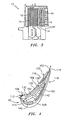
- FIG. 1 depicts an engine arrangement 10 illustrating the relative location of a high pressure turbine blade 12.
- FIGS. 2 and 3 depict the main design characteristics of a typical conventionally cooled high-pressure blade 12.
- cooling flow passes through these blades by means of internal cooling channels 14 that are turbulated with trip strips 16 for enhancing heat transfer inside the blade.
- the cooling effectiveness of these blades is around 0.50 with a convective efficiency of around 0.40.
- cooling effectiveness is a dimensionless ratio of metal temperature ranging from zero to unity as the minimum and maximum values.
- the convective efficiency is also a dimensionless ratio and denotes the ability for heat pick-up by the coolant, with zero and unity denoting no heat pick-up and maximum heat pick-up respectively.
- the blade cooling flow should not increase and if possible, even decrease for turbine efficiency improvements. That objective is extremely difficult to achieve with current cooling technology which is shown schematically in FIGS. 2 and 3 .
- the cooling flow would have to increase more than 5% of the engine core flow.
- the metal temperature in the embodiment of FIG. 3 is about 2180 degrees Fahrenheit (1193°C). This level of temperature is considered above the target limit.
- first requirement coating the airfoil with a thermal barrier coating is a first requirement.
- the other requirements are: (1) improved film cooling in terms of slots for increased film coverage; (2) improved heat pick--up; and (3) improved heat transfer coefficients in the blade cooling passages.
- the overall cooling effectiveness will approach 0.8 with a connective efficiency approaching 0.5, allowing for a lower cooling flow of no more than 3.5% of the engine core flow.
- a turbine engine component according to claim 1 is provided.
- the airfoil As noted above, to improve the cooling effectiveness and the convective efficiency, several approaches are required.
- coating the airfoil with a thermal barrier coating is a first requirement.
- the other requirements are: (1) improved film cooling in terms of slots for increased film coverage; (2) improved heat pick-up; and (3) improved heat transfer coefficients in the blade cooling passages.
- the overall cooling effectiveness will approach 0.8 with a convective efficiency approaching 0.5, allowing for lower cooling flow of no more than 3.5%.
- FIG. 4 One such design is shown in FIG. 4 .
- a turbine engine component 90 such as a high pressure turbine blade, is cooled using the cooling design scheme of the present invention.
- the cooling design scheme encompasses two serpentine microcircuits 100 and 102 located peripherally in the airfoil walls 104 and 106 respectively for cooling the main body 108 of the airfoil portion 110 of the turbine engine component.
- Separate cooling microcircuits 96 and 98 may be used to cool the leading and trailing edges 112 and 114 respectively of the airfoil main body 108.
- the coolant inside the turbine engine component may be used to feed the leading and trailing edge regions 112 and 114.
- the coolant may be ejected out of the turbine engine component by means of film cooling.
- the microcircuit 102 has a fluid inlet 126 for supplying cooling fluid to a first leg 128.
- the inlet 126 receives the cooling fluid from one of the feed cavities 142 in the turbine engine component. Fluid flowing through the first leg 128 travels to an intermediate leg 130 and from there to an outlet leg 132. Fluid supplied by one of the feed cavities 142 may also be introduced into the cooling microcircuit 96 and used to cool the leading edge 112 of the airfoil portion 110.
- Tne cooling microcircuit 96 may include fluid passageway 131 having fluid outlets 133.
- fluid from the outlet leg 132 may be used to cool the leading edge 112 via an outlet passage 135.
- the thermal load to the turbine engine component may not require film cooling from each of the legs that form the serpentine peripheral cooling microcircuit 102.
- the flow of cooling fluid may be allowed to exit from the outlet leg 132 at the tip 134 by means of film blowing from the pressure side 116 to the suction side 118 of the turbine engine component.
- the outlet leg 132 may communicate with a passageway 136 in the tip 134 having fluid outlets 138.
- the serpentine cooling microcircuit 100 for the pressure side 116 of the airfoil portion 110.
- the microcircuit 100 has an inlet 141 which communicates with one of the feed cavities 142 and a first leg 144 which receives cooling fluid from the inlet 141.
- the cooling fluid in the first leg 144 flows through the intermediate leg 146 and through the outlet leg 148.
- fluid from the feed cavity 142 may also be supplied to the trailing edge cooling microcircuit 98.
- the cooling microcircuit 98 may have a plurality of fluid passageways 150 which have outlets 152 for distributing cooling fluid over the trailing edge 114 of the airfoil portion 110.
- the outlet leg 148 may have one or more fluid outlets 153 for supplying a film of cooling fluid over the pressure side 116 of the airfoil portion 110 in the region of the trailing edge 114.
- cooling microcircuit scheme of FIGS. 4 - 6 is completely different from existing designs where a dedicated cooling passage, denoted as a tip flag is employed for cooling the tip 134.
- the pressure side 116 of the airfoil main body 108 is cooled with a serpentine microcircuit 100 located peripherally in the airfoil wall 104.
- a flow exits in a series of film cooling slots 153 close to the aft side of the airfoil 110 to protect the airfoil trailing edge 114.
- each leg 128, 130, 132, 144, 146, and 148 of the serpentine cooling microcircuits 100 and 102 may be provided with one or more internal features (not shown), such as pedestals and/or trip strips, to enhance the heat pick-up and increase the heat transfer coefficients characteristics inside the cooling blade passage(s).
- cooling microcircuits may be located around and imbedded in a platform portion 170 of the turbine blade.
- the cooling microcircuits may include a leading edge or forward cooling microcircuit 172 having an inlet portion A and an outlet portion B.
- the inlet portion A may receive fluid from one of the feed cavities 142. Fluid from the outlet portion B flows back into the cooling microcircuit 96.
- the platform cooling microcircuits may include a trailing edge or aft cooling microcircuit 180 having an inlet portion C and an outlet portion D.
- the inlet portion C may receive fluid from one of the feed cavities 142. Fluid from the outlet portion D flows into the cooling microcircuit 98.
- the platform cooling is independent of the serpentine cooling microcircuits 100 and 102 used for the airfoil portion 100.
- the inlet coolant flow to either of the leading and trailing edge cooling microcircuits 172 and 180 comes from a lower radii. This coolant flow is allowed to pass through the platform walls before discharging into the cooling microcircuit 96 or 98 at a higher radii.
- the rotational pumping which is created, along with the ejector-type action of the main flow, will ensure circulation in the peripheral platform cooling microcircuits 172 and 180.
- an integrated cooling system has been devised to cool the platform 170, the main body 108 of the airfoil portion 110, and the tip 134 of the airfoil portion 110 by taking advantage of the microcircuit cooling characteristics.
- the platform cooling microcircuits 172 and 180 may be provided with one or more internal features (not shown), such as pedestals, to enhance heat pick-up and increase the heat transfer coefficient characteristics inside the cooling passage(s) of the cooling microcircuits.
Claims (12)
- Composant de moteur à turbine (90) comportant une portion de surface portante (110) avec un côté pression (116) et un côté aspiration (118) comprenant :un premier microcircuit de refroidissement (102) noyé dans une première paroi (106) formant ledit côté aspiration (118), ledit premier microcircuit de refroidissement (102) présentant une disposition en serpentin avec une première jambe de train de refoulement (132) et comportant un moyen pour permettre à un fluide de refroidissement dans ledit premier microcircuit de refroidissement (102) de sortir au niveau d'un embout (134) de ladite portion de surface portante ;un deuxième microcircuit de refroidissement (100) noyé dans une seconde paroi (104) formant ledit côté pression (116), ledit deuxième microcircuit de refroidissement (100) présentant une disposition en serpentin avec une seconde jambe de train de refoulement (148) ;un moyen pour créer un flux de fluide de refroidissement sur un bord de fuite (114) de ladite portion de surface portante (110) ;un moyen pour créer un flux de fluide de refroidissement sur un bord d'attaque (112) de ladite portion de surface portante (110) ; etcaractérisé en ce que ledit premier microcircuit de refroidissement (102) comporte un passage de refoulement (135) pour refroidir le bord d'attaque (112) de la portion de surface portante ; et en ce que ledit deuxième microcircuit de refroidissement (100) comporte une admission (141) et ladite seconde jambe de train de refoulement (148) comporte une pluralité de refoulements de refroidissement de film pour fournir un fluide de refroidissement sur le côté pression de la portion de surface portante dans la région du bord de fuite de la portion de surface portante.
- Composant de moteur à turbine selon la revendication 1, dans lequel ledit fluide de refroidissement sort au niveau dudit embout (134) au moyen d'un soufflage de film du côté pression (116) au côté aspiration (118) de la portion de surface portante (110).
- Composant de moteur à turbine selon la revendication 1 ou 2, dans lequel ledit moyen pour créer un flux de fluide de refroidissement sur un bord de fuite (114) de ladite portion de surface portante (110) est isolé d'une charge thermique externe soit du côté pression (116), soit du côté aspiration (118) de la portion de surface portante (110).
- Composant de moteur à turbine selon la revendication 1, 2 ou 3, dans lequel ledit moyen pour créer un flux de fluide de refroidissement sur ledit bord d'attaque (112) de ladite portion de surface portante (110) est isolé d'une charge thermique externe soit du côté pression (116), soit du côté aspiration (118) de la portion de surface portante (110).
- Composant de moteur à turbine selon l'une quelconque des revendications précédentes, comprenant en outre une plate-forme (170) et un moyen pour refroidir ladite plate-forme (170).
- Composant de moteur à turbine selon la revendication 5, dans lequel ledit moyen de refroidissement de plate-forme est indépendant desdits premier et deuxième microcircuits de refroidissement (100, 102).
- Composant de moteur à turbine selon la revendication 5 ou 6, dans lequel ledit moyen de refroidissement de plate-forme comprend un troisième microcircuit de refroidissement (172) noyé dans une portion avant de ladite plate-forme (170).
- Composant de moteur à turbine selon la revendication 7, dans lequel ledit moyen de refroidissement de plate-forme comprend en outre un quatrième microcircuit de refroidissement (180) noyé dans une portion arrière de ladite plate-forme (170).
- Composant de moteur à turbine selon la revendication 8, dans lequel chacun des troisième et quatrième microcircuits de refroidissement (172, 180) comporte une admission à un premier niveau et un refoulement à un second niveau différent dudit premier niveau.
- Composant de moteur à turbine selon la revendication 9, dans lequel ledit premier niveau est inférieur audit second niveau.
- Composant de moteur à turbine selon l'une quelconque des revendications précédentes, dans lequel ledit composant (90) comprend une pale.
- Composant de moteur à turbine selon la revendication 11, dans lequel ledit composant (90) comprend une pale haute pression.
Applications Claiming Priority (2)
| Application Number | Priority Date | Filing Date | Title |
|---|---|---|---|
| US11/489,155 US7513744B2 (en) | 2006-07-18 | 2006-07-18 | Microcircuit cooling and tip blowing |
| US11/491,405 US7553131B2 (en) | 2006-07-21 | 2006-07-21 | Integrated platform, tip, and main body microcircuits for turbine blades |
Publications (2)
| Publication Number | Publication Date |
|---|---|
| EP1882819A1 EP1882819A1 (fr) | 2008-01-30 |
| EP1882819B1 true EP1882819B1 (fr) | 2010-09-08 |
Family
ID=38658627
Family Applications (1)
| Application Number | Title | Priority Date | Filing Date |
|---|---|---|---|
| EP20070252838 Active EP1882819B1 (fr) | 2006-07-18 | 2007-07-18 | Microcircuits pour pales de turbine intégrés dans la plate-forme, la pointe, et l'aube |
Country Status (2)
| Country | Link |
|---|---|
| EP (1) | EP1882819B1 (fr) |
| DE (1) | DE602007008996D1 (fr) |
Cited By (1)
| Publication number | Priority date | Publication date | Assignee | Title |
|---|---|---|---|---|
| EP3670841B1 (fr) * | 2018-11-09 | 2023-07-26 | Raytheon Technologies Corporation | Profil aérodynamique ayant un réapprovisionnement hybride du passage central de l'enveloppe |
Families Citing this family (7)
| Publication number | Priority date | Publication date | Assignee | Title |
|---|---|---|---|---|
| US9121290B2 (en) * | 2010-05-06 | 2015-09-01 | United Technologies Corporation | Turbine airfoil with body microcircuits terminating in platform |
| US20140044557A1 (en) * | 2012-08-09 | 2014-02-13 | General Electric Company | Turbine blade and method for cooling the turbine blade |
| US20140096538A1 (en) * | 2012-10-05 | 2014-04-10 | General Electric Company | Platform cooling of a turbine blade assembly |
| FR3021699B1 (fr) | 2014-05-28 | 2019-08-16 | Safran Aircraft Engines | Aube de turbine a refroidissement optimise au niveau de son bord de fuite |
| FR3021697B1 (fr) * | 2014-05-28 | 2021-09-17 | Snecma | Aube de turbine a refroidissement optimise |
| US10662780B2 (en) * | 2018-01-09 | 2020-05-26 | United Technologies Corporation | Double wall turbine gas turbine engine vane platform cooling configuration with baffle impingement |
| US10648343B2 (en) * | 2018-01-09 | 2020-05-12 | United Technologies Corporation | Double wall turbine gas turbine engine vane platform cooling configuration with main core resupply |
Family Cites Families (5)
| Publication number | Priority date | Publication date | Assignee | Title |
|---|---|---|---|---|
| US5813835A (en) * | 1991-08-19 | 1998-09-29 | The United States Of America As Represented By The Secretary Of The Air Force | Air-cooled turbine blade |
| US6991430B2 (en) * | 2003-04-07 | 2006-01-31 | General Electric Company | Turbine blade with recessed squealer tip and shelf |
| US7097424B2 (en) * | 2004-02-03 | 2006-08-29 | United Technologies Corporation | Micro-circuit platform |
| US7217092B2 (en) * | 2004-04-14 | 2007-05-15 | General Electric Company | Method and apparatus for reducing turbine blade temperatures |
| US7147439B2 (en) * | 2004-09-15 | 2006-12-12 | General Electric Company | Apparatus and methods for cooling turbine bucket platforms |
-
2007
- 2007-07-18 EP EP20070252838 patent/EP1882819B1/fr active Active
- 2007-07-18 DE DE200760008996 patent/DE602007008996D1/de active Active
Cited By (1)
| Publication number | Priority date | Publication date | Assignee | Title |
|---|---|---|---|---|
| EP3670841B1 (fr) * | 2018-11-09 | 2023-07-26 | Raytheon Technologies Corporation | Profil aérodynamique ayant un réapprovisionnement hybride du passage central de l'enveloppe |
Also Published As
| Publication number | Publication date |
|---|---|
| DE602007008996D1 (de) | 2010-10-21 |
| EP1882819A1 (fr) | 2008-01-30 |
Similar Documents
| Publication | Publication Date | Title |
|---|---|---|
| US7553131B2 (en) | Integrated platform, tip, and main body microcircuits for turbine blades | |
| EP1882820B1 (fr) | Refroidissement de microcircuit et soufflage d'extrémité d'aube | |
| EP1882819B1 (fr) | Microcircuits pour pales de turbine intégrés dans la plate-forme, la pointe, et l'aube | |
| US7699583B2 (en) | Serpentine microcircuit vortex turbulatons for blade cooling | |
| EP2236752B1 (fr) | Aube refroidie de turbine à gaz | |
| US7789626B1 (en) | Turbine blade with showerhead film cooling holes | |
| US9797261B2 (en) | Internal cooling of engine components | |
| EP1882818B1 (fr) | Générateurs de tourbillons dans microcircuits en serpentins pour refroidissement d'aube | |
| EP1783327B1 (fr) | Noyau métallique réfractaire et procédé de fabrication pour aubes de turbine | |
| EP0852284B1 (fr) | Générateur de turbulences pour les passages de refroidissement des aubes de turbine à gaz | |
| US7690894B1 (en) | Ceramic core assembly for serpentine flow circuit in a turbine blade | |
| US8398370B1 (en) | Turbine blade with multi-impingement cooling | |
| EP2204538B1 (fr) | Circuits de refroidissement de pale de turbine | |
| EP1070829B1 (fr) | Aube de turbomachine refroidie intérieurement | |
| EP1444418B1 (fr) | Aube ou pale de turbine a gaz refroidi interne | |
| US6955522B2 (en) | Method and apparatus for cooling an airfoil | |
| US7520725B1 (en) | Turbine airfoil with near-wall leading edge multi-holes cooling | |
| EP1878874B1 (fr) | Microcanaux intégrés pour aubes | |
| US8613597B1 (en) | Turbine blade with trailing edge cooling | |
| KR20070054560A (ko) | 블레이드용 마이크로회로 냉각 | |
| US8016564B1 (en) | Turbine blade with leading edge impingement cooling | |
| EP2103781B1 (fr) | Microcircuit de refroidissement de bord de fuite avec des sorties alternées convergentes | |
| EP2031186B1 (fr) | Agencement de refroidissement d'une aube d'une turbine à gaz | |
| EP1900905B1 (fr) | Gestion thermique d'une aube avec refroidissement par microcircuit | |
| EP2752554A1 (fr) | Pale pour turbomachine |
Legal Events
| Date | Code | Title | Description |
|---|---|---|---|
| PUAI | Public reference made under article 153(3) epc to a published international application that has entered the european phase |
Free format text: ORIGINAL CODE: 0009012 |
|
| AK | Designated contracting states |
Kind code of ref document: A1 Designated state(s): AT BE BG CH CY CZ DE DK EE ES FI FR GB GR HU IE IS IT LI LT LU LV MC MT NL PL PT RO SE SI SK TR |
|
| AX | Request for extension of the european patent |
Extension state: AL BA HR MK YU |
|
| 17P | Request for examination filed |
Effective date: 20080116 |
|
| 17Q | First examination report despatched |
Effective date: 20080306 |
|
| AKX | Designation fees paid |
Designated state(s): DE GB |
|
| GRAP | Despatch of communication of intention to grant a patent |
Free format text: ORIGINAL CODE: EPIDOSNIGR1 |
|
| GRAS | Grant fee paid |
Free format text: ORIGINAL CODE: EPIDOSNIGR3 |
|
| GRAA | (expected) grant |
Free format text: ORIGINAL CODE: 0009210 |
|
| AK | Designated contracting states |
Kind code of ref document: B1 Designated state(s): DE GB |
|
| REG | Reference to a national code |
Ref country code: GB Ref legal event code: FG4D |
|
| REF | Corresponds to: |
Ref document number: 602007008996 Country of ref document: DE Date of ref document: 20101021 Kind code of ref document: P |
|
| PLBE | No opposition filed within time limit |
Free format text: ORIGINAL CODE: 0009261 |
|
| STAA | Information on the status of an ep patent application or granted ep patent |
Free format text: STATUS: NO OPPOSITION FILED WITHIN TIME LIMIT |
|
| 26N | No opposition filed |
Effective date: 20110609 |
|
| REG | Reference to a national code |
Ref country code: DE Ref legal event code: R097 Ref document number: 602007008996 Country of ref document: DE Effective date: 20110609 |
|
| REG | Reference to a national code |
Ref country code: DE Ref legal event code: R082 Ref document number: 602007008996 Country of ref document: DE Representative=s name: SCHMITT-NILSON SCHRAUD WAIBEL WOHLFROM PATENTA, DE |
|
| REG | Reference to a national code |
Ref country code: DE Ref legal event code: R082 Ref document number: 602007008996 Country of ref document: DE Representative=s name: SCHMITT-NILSON SCHRAUD WAIBEL WOHLFROM PATENTA, DE Ref country code: DE Ref legal event code: R081 Ref document number: 602007008996 Country of ref document: DE Owner name: UNITED TECHNOLOGIES CORP. (N.D.GES.D. STAATES , US Free format text: FORMER OWNER: UNITED TECHNOLOGIES CORP. (N.D.GES.D. STAATES DELAWARE), HARTFORD, CONN., US |
|
| PGFP | Annual fee paid to national office [announced via postgrant information from national office to epo] |
Ref country code: DE Payment date: 20200622 Year of fee payment: 14 |
|
| REG | Reference to a national code |
Ref country code: DE Ref legal event code: R119 Ref document number: 602007008996 Country of ref document: DE |
|
| PG25 | Lapsed in a contracting state [announced via postgrant information from national office to epo] |
Ref country code: DE Free format text: LAPSE BECAUSE OF NON-PAYMENT OF DUE FEES Effective date: 20220201 |
|
| REG | Reference to a national code |
Ref country code: DE Ref legal event code: R081 Ref document number: 602007008996 Country of ref document: DE Owner name: RAYTHEON TECHNOLOGIES CORPORATION (N.D.GES.D.S, US Free format text: FORMER OWNER: UNITED TECHNOLOGIES CORP. (N.D.GES.D. STAATES DELAWARE), FARMINGTON, CONN., US |
|
| PGFP | Annual fee paid to national office [announced via postgrant information from national office to epo] |
Ref country code: GB Payment date: 20230620 Year of fee payment: 17 |