EP1882809A1 - Methods and apparatus for micro-imaging - Google Patents
Methods and apparatus for micro-imaging Download PDFInfo
- Publication number
- EP1882809A1 EP1882809A1 EP06291222A EP06291222A EP1882809A1 EP 1882809 A1 EP1882809 A1 EP 1882809A1 EP 06291222 A EP06291222 A EP 06291222A EP 06291222 A EP06291222 A EP 06291222A EP 1882809 A1 EP1882809 A1 EP 1882809A1
- Authority
- EP
- European Patent Office
- Prior art keywords
- drill bit
- optical probe
- probe
- hole
- formation
- Prior art date
- Legal status (The legal status is an assumption and is not a legal conclusion. Google has not performed a legal analysis and makes no representation as to the accuracy of the status listed.)
- Granted
Links
Images



Classifications
-
- E—FIXED CONSTRUCTIONS
- E21—EARTH OR ROCK DRILLING; MINING
- E21B—EARTH OR ROCK DRILLING; OBTAINING OIL, GAS, WATER, SOLUBLE OR MELTABLE MATERIALS OR A SLURRY OF MINERALS FROM WELLS
- E21B49/00—Testing the nature of borehole walls; Formation testing; Methods or apparatus for obtaining samples of soil or well fluids, specially adapted to earth drilling or wells
- E21B49/08—Obtaining fluid samples or testing fluids, in boreholes or wells
- E21B49/10—Obtaining fluid samples or testing fluids, in boreholes or wells using side-wall fluid samplers or testers
-
- E—FIXED CONSTRUCTIONS
- E21—EARTH OR ROCK DRILLING; MINING
- E21B—EARTH OR ROCK DRILLING; OBTAINING OIL, GAS, WATER, SOLUBLE OR MELTABLE MATERIALS OR A SLURRY OF MINERALS FROM WELLS
- E21B47/00—Survey of boreholes or wells
- E21B47/002—Survey of boreholes or wells by visual inspection
Definitions
- This invention relates to methods and apparatus for imaging underground formations and fluids such as are commonly encountered in the drilling of wells such as oil and gas wells.
- the invention provides apparatus for use as a tool for making measurements in such wells.
- a number of optical techniques have also been proposed for viewing the formation surrounding a borehole.
- the borehole is filled with an optically clear fluid (water or oil), and a tool carrying a camera and light source is passed along the borehole.
- Conical or hemispherical mirrors or fish-eye lenses have been proposed to obtain full azimuthal coverage for a camera placed at or near the centre line of the borehole.
- an optical window is provided in the side of a tool or pad which is pressed against the borehole wall and measurements made.
- Another problem is that borehole fluids, formation fluids or mudcake can coat the viewing window or get between the window and the formation and prevent an image being obtained.
- This invention is aimed at solving the problem of investigating the formation in a regions that are less effected by the drilling process and in a manner that avoids problems with contaminant coming between the imaging tool and the formation preventing an image being obtained.
- a first aspect of the invention provides an apparatus for investigating underground formations surrounding a borehole, comprising:
- the optical surface of the probe can be held close enough to the formation in the drilled hole that the level of degradation due to material between the probe and the formation is sufficiently low as to allow effective investigation of the formation. Drilling into the formation means that the formation 'viewed' by the tool is less affected by the drilling process.
- the drill bit and optical probe form a single, elongate probe unit.
- the drill bit is mounted on the end of the optical probe.
- the optical system can comprise a conical mirror located at the joint between the drill bit and optical probe.
- the drive mechanism can be arranged to act on the optical probe to cause the drill bit to drill the hole.
- the drill bit is provided with a liquid pathway to direct any formation fluid entering the drilled hole back along the probe unit.
- the liquid path typically leads to a capillary trap in the probe unit at which the fluid can be analysed.
- the drill bit and optical probe are two discrete units.
- the optical system can comprise a conical mirror located in the optical probe.
- the drive mechanism preferably includes means for aligning the drill bit or the optical probe with the position of the drilled hole.
- Apparatus according to the invention preferably further comprises a tool body in which are located the drive mechanism, a light source and a detector and at least part of the optical system.
- the body can also include arms which can be operated to bear against the borehole wall so as to urge the tool body against the part of the borehole wall into which the hole is to be drilled.
- a second aspect of the invention provides a method of investigating underground formations surrounding a borehole, comprising:
- the optical probe can be used to turn the drill bit such that as the drill bit drills into the formation, the optical probe is inserted into the drilled hole.
- the method preferably further comprises drawing the fluids along the drill bit to the optical probe and analysing the fluids using the optical probe.
- the drill bit is withdrawn from the hole and the optical probe subsequently inserted.
- the method according to the second aspect of the invention is preferably performed using an apparatus according to the first aspect of the invention.
- Figures 1 and 2 show a tool according to a first embodiment of the invention
- Figures 1 and 2 show a first embodiment of a tool according to the invention.
- the tool comprises a tool body 10 that can be suspended in a borehole 12 by means of a wireline cable (not shown) which provides power and data communication from the surface.
- a pair of backup arms 14 are mounted on the tool body and can be extended to contact one side of the borehole wall 16 so as to force the tool body 10 against the opposite side of the borehole wall 18 where it is supported on pads 20.
- a drive mechanism 22 comprising a motor and gear arrangement is mounted in the body 10.
- the drive mechanism includes a drive head 24 in which is mounted a drill and probe unit 26.
- the unit 26 comprises at its outer end a drill bit 28 and at its inner end an optical probe 30 formed from a sapphire fibre having an outside diameter that is substantially the same as, but no larger than that of the drill bit.
- the drive mechanism 24, which is provide with power and control signals from the wireline cable, operates to rotate the drill unit 26 and provide an axial drive to either drill into the borehole wall 18 or withdraw the unit from a drilled hole.
- the body 10 also contains an optical system comprising a CCD camera and light source 32 with associated control electronics 34.
- the optical system also includes a mirror 36 which provides a light path 38 to direct light from the light source into the fibre forming the optical probe 30, and to direct light exiting the optical probe to the CCD camera.
- Figure 1 shows the configuration of the tool when it is positioned in the borehole 12 adjacent a formation of interest.
- Figure 2 shows the configuration of the tool once a hole has been drilled and the drill and probe unit 26 advanced into the drilled hole such that at least the lower part of the optical probe 30 is located in the hole.
- FIG. 3 shows further detail of the drill and probe unit 26.
- the drill bit 28 is metallic and has an end portion 40 for drilling ahead and a tail portion 42 which is shaped with grooves 44 to remove the drilled material, and to polish or hone the wall of the drilled hole to obtain a good surface for imaging.
- the sapphire fibre 46 forming the optical probe 30 is fixed to the end of the drill bit 28.
- the outer diameter of the fibre 46 is close to, but no greater than the largest outer diameter of any part of the drill bit 28 (for example 5-12mm) so as to be able to fit in the drilled hole but to leave as little possible space between the wall of the drilled hole and the side of the fibre 46.
- a conical mirror 48 is formed at the interface between the drill bit 28 and optical probe 30.
- Light entering the probe from the source 32 via the mirror 36 is reflected substantially equally around the azimuth of the fibre 46 onto an investigation zone 50 of the hole wall near the conical mirror 48.
- Light passing into the fibre from the investigation zone 50 is reflected by the conical mirror 48 back up the fibre 46 and via the mirror 36 to the CCD camera 32.
- light from the source 32 can be directed at the polished or honed surface of the drilled hole in the investigation zone 50 and an optical image of the wall (and hence the formation) returned to the camera 32.
- Such a probe can be used to obtain optical images on the order of 1 micron resolution.
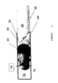
- the drill and probe unit 26 to analyse formation fluids as is shown in Figure 4. Because of the close fit between the outside of the probe unit 26 and the wall of the drilled hole, when the probe unit 26 is withdrawn from the hole, a pressure drop is created at the end of the hole 52 by the swabbing effect such that fluids can flow in from the formation 18. The fluids can flow back along the groves 44 and 44' to the region of the fibre 46 near the mirror 48 where they can be trapped in a capillary chamber 54 and optically analysed in a similar fashion to that described above for the formation wall.
- the steps of drilling, imaging and fluid analysis can be repeated several times, repositioning the tool in the borehole prior to each measurement.
- Figures 5 and 6 show a second embodiment of a tool according to the invention. Parts corresponding to those in Figures 1 and 2 are given the same numbers in the 100 series.
- This second embodiment differs from the first in that the drill probe unit is replaced by a separate drill bit 128 and optical probe 130.
- the drive head 124 has the bit 128 and probe 130 carried separately and the drive mechanism 122 includes a translation mechanism to align one or the other with the position of the drilled hole.
- the tool In the first stage or operation, as shown in Figure 5, the tool is positioned as before and the drive mechanism 122 operated to drill the hole with the drill bit 128. The mechanism 122 then withdraws the bit 128 from the hole and moves the drive head 124 until the optical probe 130 is aligned with the hole ( Figure 6), at which point it is inserted into the hole and the optical measurement made. The probe 130 can then be withdrawn from the hole and the tool moved to another location for further measurements to be made.
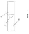
- the optical probe can have a somewhat different construction as is shown in Figure 7, comprising a multi-part sapphire-sapphire assembly 60, 62 having a conical mirror 64 formed at the interface.
- a probe diameter corresponding to that of the OD of the drill bit 128 is used, 5-12mm for example.
- the light returning to the CCD camera 32 can be processed in the tool electronics 34 to form images which can be either stored in the tool or transmitted to the surface via the wireline cable. Also, the raw optical signals can be stored or transmitted to the surface for later processing.
- the tool can be self contained without the need to rely on the wireline cable for instructions and/or power.
- the tool can also be conveyed on coiled tubing. While the examples given above contemplate imaging in open (uncased) boreholes, the invention could also be used in cased boreholes but with the necessity of drilling through casing and any cement between the casing and formation before obtaining images. Plugging of holes drilled in casing may also be required.
- the optical probe is provided with a small internal hole that can be connected in the tool body to a pumping arrangement.
- This hole can be used for the withdrawal of liquid from the drilled hole in order to measure the formation pressure.
- the hole can also be used to inject a very small quantity of liquid (water for instance) in order to flush the probe in cases where the optical attenuation is high, for example in heavy mud. Since the amount of liquid surrounding the probe in the drilled hole (for the dimensions described above) is very small (about one cc) it can easily be replaced or diluted with a clean fluid ejected from the hole in the probe.
Landscapes
- Life Sciences & Earth Sciences (AREA)
- Engineering & Computer Science (AREA)
- Geology (AREA)
- Mining & Mineral Resources (AREA)
- Physics & Mathematics (AREA)
- Environmental & Geological Engineering (AREA)
- Fluid Mechanics (AREA)
- General Life Sciences & Earth Sciences (AREA)
- Geochemistry & Mineralogy (AREA)
- Geophysics (AREA)
- Geophysics And Detection Of Objects (AREA)
- Auxiliary Devices For And Details Of Packaging Control (AREA)
Abstract
Description
- This invention relates to methods and apparatus for imaging underground formations and fluids such as are commonly encountered in the drilling of wells such as oil and gas wells. In particular, the invention provides apparatus for use as a tool for making measurements in such wells.
- There are a number of techniques that have been proposed for obtaining images of underground formations around boreholes. In some of these techniques, small-scale electrical, acoustic or nuclear properties are measured and an image reconstructed from these measurements. In all of these cases, the image is inferred: it does not correspond exactly to what a person would see if viewing it directly.
- A number of optical techniques have also been proposed for viewing the formation surrounding a borehole. In one such technique, the borehole is filled with an optically clear fluid (water or oil), and a tool carrying a camera and light source is passed along the borehole. Conical or hemispherical mirrors or fish-eye lenses have been proposed to obtain full azimuthal coverage for a camera placed at or near the centre line of the borehole.
- In another class of optical techniques an optical window is provided in the side of a tool or pad which is pressed against the borehole wall and measurements made.
- All of these optical techniques suffer from problems. In all cases, the formation viewed is that left after the drilling operation has been performed. It is well known that drilling can cause significant changes in the formation around a borehole. For example, the drilling action can cause mechanical damage, and drilling fluids can enter the formations (invasion) or cause the formations to undergo changes such swelling. Consequently, viewing such a formation may not be a good way to understand the nature of the formation in its normal state. The typical imaging resolution is of the order of 1 cm.
- Another problem is that borehole fluids, formation fluids or mudcake can coat the viewing window or get between the window and the formation and prevent an image being obtained.
- This invention is aimed at solving the problem of investigating the formation in a regions that are less effected by the drilling process and in a manner that avoids problems with contaminant coming between the imaging tool and the formation preventing an image being obtained.
- A first aspect of the invention provides an apparatus for investigating underground formations surrounding a borehole, comprising:
- a drill bit;
- an optical probe having substantially the same outer diameter as the drill bit;
- a drive mechanism, operable to cause the drill bit to drill a hole in the formation when the apparatus is in the borehole, and to advance the optical probe into the drilled hole; and
- an optical system, arranged such that when the optical probe is in the drilled hole, light from a light source is directed into the optical probe, light entering the probe from the source is directed at the formation around the drilled hole, and light entering the probe from the formation around the drilled hole is directed to a detector.
- By providing an optical probe with substantially the same diameter as the drill bit, the optical surface of the probe can be held close enough to the formation in the drilled hole that the level of degradation due to material between the probe and the formation is sufficiently low as to allow effective investigation of the formation. Drilling into the formation means that the formation 'viewed' by the tool is less affected by the drilling process.
- In one preferred embodiment, the drill bit and optical probe form a single, elongate probe unit. In this case, it is preferred that the drill bit is mounted on the end of the optical probe. The optical system can comprise a conical mirror located at the joint between the drill bit and optical probe.
- Where the drill bit and optical probe are provided in one unit, the drive mechanism can be arranged to act on the optical probe to cause the drill bit to drill the hole.
- In one preferred form of this embodiment, the drill bit is provided with a liquid pathway to direct any formation fluid entering the drilled hole back along the probe unit. The liquid path typically leads to a capillary trap in the probe unit at which the fluid can be analysed.
- In another embodiment of the invention, the drill bit and optical probe are two discrete units. In this case, the optical system can comprise a conical mirror located in the optical probe.
- In this embodiment, the drive mechanism preferably includes means for aligning the drill bit or the optical probe with the position of the drilled hole.
- Apparatus according to the invention preferably further comprises a tool body in which are located the drive mechanism, a light source and a detector and at least part of the optical system. The body can also include arms which can be operated to bear against the borehole wall so as to urge the tool body against the part of the borehole wall into which the hole is to be drilled.
- A second aspect of the invention provides a method of investigating underground formations surrounding a borehole, comprising:
- drilling a hole in the formation to be investigated using a drill bit;
- inserting an optical probe having substantially the same outer diameter as the drill bit into the hole;
- directing light from a light source to the probe;
- directing light entering the optical probe to the formation around the drilled hole;
- directing light entering the optical probe from the formation to a detector; and
- analysing the light received at the detector.
- The optical probe can be used to turn the drill bit such that as the drill bit drills into the formation, the optical probe is inserted into the drilled hole.
- By partially withdrawing the drill bit in the drilled hole, fluids can be drawn from the formation into the drilled hole. In this case, the method preferably further comprises drawing the fluids along the drill bit to the optical probe and analysing the fluids using the optical probe.
- In another embodiment of the method according to the invention, after drilling the hole using the drill bit, the drill bit is withdrawn from the hole and the optical probe subsequently inserted.
- The method according to the second aspect of the invention is preferably performed using an apparatus according to the first aspect of the invention.
- Figures 1 and 2 show a tool according to a first embodiment of the invention;
- Figure 3 shows a detailed view of the drill probe unit of the embodiment of Figures 1 and 2;
- Figure 4 shows the drill probe of Figure 3 when used for fluid analysis;
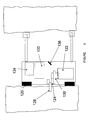
- Figures 5 and 6 show a tool according to a second embodiment of the invention; and
- Figure 7 shows a detailed view of the optical probe of the embodiment of Figures 5 and 6.
- Figures 1 and 2 show a first embodiment of a tool according to the invention. The tool comprises a
tool body 10 that can be suspended in aborehole 12 by means of a wireline cable (not shown) which provides power and data communication from the surface. A pair ofbackup arms 14 are mounted on the tool body and can be extended to contact one side of theborehole wall 16 so as to force thetool body 10 against the opposite side of theborehole wall 18 where it is supported onpads 20. - A
drive mechanism 22 comprising a motor and gear arrangement is mounted in thebody 10. The drive mechanism includes adrive head 24 in which is mounted a drill andprobe unit 26. Theunit 26 comprises at its outer end adrill bit 28 and at its inner end anoptical probe 30 formed from a sapphire fibre having an outside diameter that is substantially the same as, but no larger than that of the drill bit. Thedrive mechanism 24, which is provide with power and control signals from the wireline cable, operates to rotate thedrill unit 26 and provide an axial drive to either drill into theborehole wall 18 or withdraw the unit from a drilled hole. - The
body 10 also contains an optical system comprising a CCD camera andlight source 32 with associatedcontrol electronics 34. The optical system also includes amirror 36 which provides alight path 38 to direct light from the light source into the fibre forming theoptical probe 30, and to direct light exiting the optical probe to the CCD camera. - Figure 1 shows the configuration of the tool when it is positioned in the borehole 12 adjacent a formation of interest. Figure 2 shows the configuration of the tool once a hole has been drilled and the drill and
probe unit 26 advanced into the drilled hole such that at least the lower part of theoptical probe 30 is located in the hole. - Figure 3 shows further detail of the drill and
probe unit 26. Thedrill bit 28 is metallic and has anend portion 40 for drilling ahead and atail portion 42 which is shaped withgrooves 44 to remove the drilled material, and to polish or hone the wall of the drilled hole to obtain a good surface for imaging. Thesapphire fibre 46 forming theoptical probe 30 is fixed to the end of thedrill bit 28. The outer diameter of thefibre 46 is close to, but no greater than the largest outer diameter of any part of the drill bit 28 (for example 5-12mm) so as to be able to fit in the drilled hole but to leave as little possible space between the wall of the drilled hole and the side of thefibre 46. This has the effect of minimising the amount of material that can remain between the side of thefibre 46 and the wall of the drilled hole which could otherwise interfere with optical measurements. Grooves 44', corresponding to those in thedrill bit 28 are formed in the outer surface of thefibre 46 to direct drilled material out of the hole and away from the wall to be imaged. - A
conical mirror 48 is formed at the interface between thedrill bit 28 andoptical probe 30. Light entering the probe from thesource 32 via themirror 36 is reflected substantially equally around the azimuth of thefibre 46 onto aninvestigation zone 50 of the hole wall near theconical mirror 48. Light passing into the fibre from theinvestigation zone 50 is reflected by theconical mirror 48 back up thefibre 46 and via themirror 36 to theCCD camera 32. Thus, light from thesource 32 can be directed at the polished or honed surface of the drilled hole in theinvestigation zone 50 and an optical image of the wall (and hence the formation) returned to thecamera 32. Such a probe can be used to obtain optical images on the order of 1 micron resolution. - As well as the optical image, the drill and
probe unit 26 to analyse formation fluids as is shown in Figure 4. Because of the close fit between the outside of theprobe unit 26 and the wall of the drilled hole, when theprobe unit 26 is withdrawn from the hole, a pressure drop is created at the end of thehole 52 by the swabbing effect such that fluids can flow in from theformation 18. The fluids can flow back along thegroves 44 and 44' to the region of thefibre 46 near themirror 48 where they can be trapped in acapillary chamber 54 and optically analysed in a similar fashion to that described above for the formation wall. - The steps of drilling, imaging and fluid analysis can be repeated several times, repositioning the tool in the borehole prior to each measurement.
- Figures 5 and 6 show a second embodiment of a tool according to the invention. Parts corresponding to those in Figures 1 and 2 are given the same numbers in the 100 series.
- This second embodiment differs from the first in that the drill probe unit is replaced by a
separate drill bit 128 andoptical probe 130. In this case, thedrive head 124 has thebit 128 and probe 130 carried separately and thedrive mechanism 122 includes a translation mechanism to align one or the other with the position of the drilled hole. - In the first stage or operation, as shown in Figure 5, the tool is positioned as before and the
drive mechanism 122 operated to drill the hole with thedrill bit 128. Themechanism 122 then withdraws thebit 128 from the hole and moves thedrive head 124 until theoptical probe 130 is aligned with the hole (Figure 6), at which point it is inserted into the hole and the optical measurement made. Theprobe 130 can then be withdrawn from the hole and the tool moved to another location for further measurements to be made. - In this embodiment, the optical probe can have a somewhat different construction as is shown in Figure 7, comprising a multi-part sapphire-
sapphire assembly conical mirror 64 formed at the interface. Again, a probe diameter corresponding to that of the OD of thedrill bit 128 is used, 5-12mm for example. - In both embodiments, the light returning to the
CCD camera 32 can be processed in thetool electronics 34 to form images which can be either stored in the tool or transmitted to the surface via the wireline cable. Also, the raw optical signals can be stored or transmitted to the surface for later processing. - Other changes can be made while staying within the scope of the invention. For example, the tool can be self contained without the need to rely on the wireline cable for instructions and/or power. The tool can also be conveyed on coiled tubing. While the examples given above contemplate imaging in open (uncased) boreholes, the invention could also be used in cased boreholes but with the necessity of drilling through casing and any cement between the casing and formation before obtaining images. Plugging of holes drilled in casing may also be required.
- In another embodiment, the optical probe is provided with a small internal hole that can be connected in the tool body to a pumping arrangement. This hole can be used for the withdrawal of liquid from the drilled hole in order to measure the formation pressure. The hole can also be used to inject a very small quantity of liquid (water for instance) in order to flush the probe in cases where the optical attenuation is high, for example in heavy mud. Since the amount of liquid surrounding the probe in the drilled hole (for the dimensions described above) is very small (about one cc) it can easily be replaced or diluted with a clean fluid ejected from the hole in the probe.
Claims (19)
- Apparatus for investigating underground formations surrounding a borehole, comprising:- a drill bit;- an optical probe having substantially the same outer diameter as the drill bit;- a drive mechanism, operable to cause the drill bit to drill a hole in the formation when the apparatus is in the borehole, and to advance the optical probe into the drilled hole; and- an optical system, arranged such that when the optical probe is in the drilled hole, light from a light source is directed into the optical probe, light entering the probe from the source is directed at the formation around the drilled hole, and light entering the probe from the formation around the drilled hole is directed to a detector.
- Apparatus as claimed in claim 1, wherein the drill bit and optical probe form a single, elongate probe unit.
- Apparatus as claimed in claim 2, wherein the drill bit is mounted on the end of the optical probe.
- Apparatus as claimed in claim 3, wherein the optical system comprises a conical mirror located at the joint between the drill bit and optical probe.
- Apparatus as claimed in any of claims 2-4, wherein the drive mechanism acts on the optical probe to cause the drill bit to drill the hole.
- Apparatus as claimed in any of claims 2-5, wherein the drill bit is provided with a liquid pathway to direct any formation fluid entering the drilled hole back along the probe unit.
- Apparatus as claimed in claim 6, wherein the liquid path leads to a capillary trap in the probe unit at which the fluid can be analysed.
- Apparatus as claimed in claim 1, wherein the drill bit and optical probe are two discrete units.
- Apparatus as claimed in claim 8, wherein the optical system comprises a conical mirror located in the optical probe.
- Apparatus as claimed in claim 8 or 9, wherein the drive mechanism includes means for aligning the drill bit or the optical probe with the position of the drilled hole.
- Apparatus as claimed in any preceding claim, further comprising a tool body in which are located the drive mechanism, a light source and a detector and at least part of the optical system.
- Apparatus as claimed in claim 11, wherein the body also includes arms which can be operated to bear against the borehole wall so as to urge the tool body against the part of the borehole wall into which the hole is to be drilled.
- Apparatus as claimed in any preceding claim, wherein the optical probe further comprises a bore through which fluids can be withdrawn from or pumped into the drilled hole.
- A method of investigating underground formations surrounding a borehole, comprising:- drilling a hole in the formation to be investigated using a drill bit;- inserting an optical probe having substantially the same outer diameter as the drill bit into the hole;- directing light from a light source to the probe;- directing light entering the optical probe to the formation around the drilled hole;- directing light entering the optical probe from the formation to a detector; and- analysing the light received at the detector.
- A method as claimed in claim 14, comprising using the optical probe to turn the drill bit such that as the drill bit drills into the formation, the optical probe is inserted into the drilled hole.
- A method as claimed in claim 15, further comprising at least partially withdrawing the drill bit in the drilled hole so as to draw fluids from the formation into the drilled hole.
- A method as claimed in claim 16, further comprising drawing the fluids along the drill bit to the optical probe and analysing the fluids using the optical probe.
- A method as claimed in claim 14, comprising, after drilling the hole using the drill bit, withdrawing the drill bit from the hole and subsequently inserting the optical probe.
- A method as claimed in claim 14, when performed using an apparatus as claimed in any of claims 1-13.
Priority Applications (5)
| Application Number | Priority Date | Filing Date | Title |
|---|---|---|---|
| EP06291222A EP1882809B1 (en) | 2006-07-24 | 2006-07-24 | Methods and apparatus for micro-imaging |
| DE602006021294T DE602006021294D1 (en) | 2006-07-24 | 2006-07-24 | Method and apparatus for microimaging |
| AT06291222T ATE505623T1 (en) | 2006-07-24 | 2006-07-24 | METHOD AND APPARATUS FOR MICROIMAGING |
| PCT/EP2007/006478 WO2008012035A1 (en) | 2006-07-24 | 2007-07-19 | Methods and apparatus for micro-imaging |
| US12/374,706 US20100026998A1 (en) | 2006-07-24 | 2007-07-19 | Methods and apparatus for micro-imaging |
Applications Claiming Priority (1)
| Application Number | Priority Date | Filing Date | Title |
|---|---|---|---|
| EP06291222A EP1882809B1 (en) | 2006-07-24 | 2006-07-24 | Methods and apparatus for micro-imaging |
Publications (2)
| Publication Number | Publication Date |
|---|---|
| EP1882809A1 true EP1882809A1 (en) | 2008-01-30 |
| EP1882809B1 EP1882809B1 (en) | 2011-04-13 |
Family
ID=37309276
Family Applications (1)
| Application Number | Title | Priority Date | Filing Date |
|---|---|---|---|
| EP06291222A Not-in-force EP1882809B1 (en) | 2006-07-24 | 2006-07-24 | Methods and apparatus for micro-imaging |
Country Status (5)
| Country | Link |
|---|---|
| US (1) | US20100026998A1 (en) |
| EP (1) | EP1882809B1 (en) |
| AT (1) | ATE505623T1 (en) |
| DE (1) | DE602006021294D1 (en) |
| WO (1) | WO2008012035A1 (en) |
Cited By (1)
| Publication number | Priority date | Publication date | Assignee | Title |
|---|---|---|---|---|
| WO2013109277A1 (en) | 2012-01-19 | 2013-07-25 | Halliburton Energy Services, Inc. | Fossil recognition apparatus, systems, and methods |
Citations (7)
| Publication number | Priority date | Publication date | Assignee | Title |
|---|---|---|---|---|
| DD100517A1 (en) * | 1972-10-11 | 1973-09-20 | ||
| US3992095A (en) * | 1975-06-09 | 1976-11-16 | Trw Systems & Energy | Optics module for borehole stress measuring instrument |
| EP0747569A2 (en) * | 1995-06-07 | 1996-12-11 | Schlumberger Limited (a Netherland Antilles corp.) | Down-hole tool and method for providing images of earth formations on a microscopic scale |
| GB2345753A (en) * | 1999-01-12 | 2000-07-19 | Baker Hughes Inc | Optical probe for analysis of formation fluids |
| WO2004003506A2 (en) * | 2002-06-26 | 2004-01-08 | Well-Dog, Inc. | In-situ detection and analysis of coal bed methane formations |
| EP1388615A1 (en) * | 2002-08-06 | 2004-02-11 | ABB Immobilien AG | Method and apparatus for soil examination |
| WO2005116401A1 (en) * | 2004-05-28 | 2005-12-08 | Deutsche Montan Technologie Gmbh | Device for examining rotor drilled holes |
Family Cites Families (11)
| Publication number | Priority date | Publication date | Assignee | Title |
|---|---|---|---|---|
| US3761186A (en) * | 1972-01-17 | 1973-09-25 | Itt | Apparatus for optically inspecting the condition of a surface having known variations in the condition |
| US5004339A (en) * | 1979-02-27 | 1991-04-02 | Diffracto Ltd. | Method and apparatus for determining physical characteristics of objects and object surfaces |
| US4281929A (en) * | 1979-05-17 | 1981-08-04 | The United States Of America As Represented By The United States Department Of Energy | Small diameter, deep bore optical inspection system |
| DE3232904A1 (en) * | 1982-09-04 | 1984-03-08 | Robert Bosch Gmbh, 7000 Stuttgart | PROBE FOR AUTOMATICALLY INSPECTING SURFACES |
| DE3422271C2 (en) * | 1984-06-15 | 1987-01-15 | Bergwerksverband Gmbh, 4300 Essen | Borehole investigation procedures |
| US4849626A (en) * | 1987-11-13 | 1989-07-18 | The Babcock & Wilcox Company | Fiber optic bore inspection probe |
| US5435176A (en) * | 1993-11-01 | 1995-07-25 | Terranalysis Corporation | Hazardous waste characterizer and remediation method and system |
| US5767510A (en) * | 1996-04-15 | 1998-06-16 | Schlumberger Technology Corporation | Borehole invariant porosity measurement system |
| US5717455A (en) * | 1996-07-02 | 1998-02-10 | Raax Co., Ltd. | System and method for three dimensional image acquisition and processing of a borehole wall |
| CN1997871B (en) * | 2004-06-08 | 2011-06-08 | 微-埃普西龙测量技术有限两合公司 | Device and method for inspecting the internal surfaces of holes |
| US20060272392A1 (en) * | 2004-12-02 | 2006-12-07 | Construction Technology Laboratories, Inc. | Relative humidity probe for concrete |
-
2006
- 2006-07-24 EP EP06291222A patent/EP1882809B1/en not_active Not-in-force
- 2006-07-24 AT AT06291222T patent/ATE505623T1/en not_active IP Right Cessation
- 2006-07-24 DE DE602006021294T patent/DE602006021294D1/en active Active
-
2007
- 2007-07-19 WO PCT/EP2007/006478 patent/WO2008012035A1/en not_active Ceased
- 2007-07-19 US US12/374,706 patent/US20100026998A1/en not_active Abandoned
Patent Citations (7)
| Publication number | Priority date | Publication date | Assignee | Title |
|---|---|---|---|---|
| DD100517A1 (en) * | 1972-10-11 | 1973-09-20 | ||
| US3992095A (en) * | 1975-06-09 | 1976-11-16 | Trw Systems & Energy | Optics module for borehole stress measuring instrument |
| EP0747569A2 (en) * | 1995-06-07 | 1996-12-11 | Schlumberger Limited (a Netherland Antilles corp.) | Down-hole tool and method for providing images of earth formations on a microscopic scale |
| GB2345753A (en) * | 1999-01-12 | 2000-07-19 | Baker Hughes Inc | Optical probe for analysis of formation fluids |
| WO2004003506A2 (en) * | 2002-06-26 | 2004-01-08 | Well-Dog, Inc. | In-situ detection and analysis of coal bed methane formations |
| EP1388615A1 (en) * | 2002-08-06 | 2004-02-11 | ABB Immobilien AG | Method and apparatus for soil examination |
| WO2005116401A1 (en) * | 2004-05-28 | 2005-12-08 | Deutsche Montan Technologie Gmbh | Device for examining rotor drilled holes |
Cited By (4)
| Publication number | Priority date | Publication date | Assignee | Title |
|---|---|---|---|---|
| WO2013109277A1 (en) | 2012-01-19 | 2013-07-25 | Halliburton Energy Services, Inc. | Fossil recognition apparatus, systems, and methods |
| EP2798153A4 (en) * | 2012-01-19 | 2015-04-08 | Halliburton Energy Serv Inc | Fossil recognition apparatus, systems, and methods |
| AU2012366288B2 (en) * | 2012-01-19 | 2016-06-16 | Halliburton Energy Services, Inc. | Fossil recognition apparatus, systems, and methods |
| US9690989B2 (en) | 2012-01-19 | 2017-06-27 | Halliburton Energy Services, Inc. | Fossil recognition apparatus, systems, and methods |
Also Published As
| Publication number | Publication date |
|---|---|
| ATE505623T1 (en) | 2011-04-15 |
| EP1882809B1 (en) | 2011-04-13 |
| US20100026998A1 (en) | 2010-02-04 |
| DE602006021294D1 (en) | 2011-05-26 |
| WO2008012035A1 (en) | 2008-01-31 |
Similar Documents
| Publication | Publication Date | Title |
|---|---|---|
| US9163500B2 (en) | Extendable and elongating mechanism for centralizing a downhole tool within a subterranean wellbore | |
| US7469746B2 (en) | Downhole sampling tool and method for using same | |
| RU2331753C2 (en) | Downhole tool | |
| US7958936B2 (en) | Downhole formation sampling | |
| CA2521151C (en) | Apparatus and methods for conveying and operating analytical instrumentation within a well borehole | |
| US8245781B2 (en) | Formation fluid sampling | |
| US8462013B2 (en) | Apparatus, system, and method for communicating while logging with wired drill pipe | |
| US9347277B2 (en) | System and method for communicating between a drill string and a logging instrument | |
| CN101285374B (en) | Method and apparatus for pipeline transport logging | |
| US8397809B2 (en) | Technique and apparatus to perform a leak off test in a well | |
| US11168562B2 (en) | Apparatus and method for performing formation stress testing in an openhole section of a borehole | |
| US9752431B2 (en) | Apparatus and method for obtaining formation fluid samples utilizing a sample clean-up device | |
| WO2009020889A1 (en) | Through-mill wellbore optical inspection and remediation apparatus and methodology | |
| FR2872540A1 (en) | APPARATUS AND METHOD FOR CHARACTERIZING UNDERGROUND FORMATION | |
| US8708041B2 (en) | Method and system for using wireline configurable wellbore instruments with a wired pipe string | |
| EP2042683A1 (en) | A logging while producing apparatus and method | |
| US8916816B2 (en) | Imaging systems and image fiber bundles for downhole measurement | |
| US7213657B2 (en) | Apparatus and methods for installing instrumentation line in a wellbore | |
| US20180298745A1 (en) | Self retracting wall contact well logging sensor | |
| US8555966B2 (en) | Formation testing apparatus and methods | |
| EP1882809B1 (en) | Methods and apparatus for micro-imaging | |
| NO20250469A1 (en) | Sealing detection during formation pressure testing | |
| NO344450B1 (en) | Method and device for formation evaluation after drilling. |
Legal Events
| Date | Code | Title | Description |
|---|---|---|---|
| PUAI | Public reference made under article 153(3) epc to a published international application that has entered the european phase |
Free format text: ORIGINAL CODE: 0009012 |
|
| AK | Designated contracting states |
Kind code of ref document: A1 Designated state(s): AT BE BG CH CY CZ DE DK EE ES FI FR GB GR HU IE IS IT LI LT LU LV MC NL PL PT RO SE SI SK TR |
|
| AX | Request for extension of the european patent |
Extension state: AL BA HR MK YU |
|
| 17P | Request for examination filed |
Effective date: 20080703 |
|
| AKX | Designation fees paid |
Designated state(s): AT BE BG CH CY CZ DE DK EE ES FI FR GB GR HU IE IS IT LI LT LU LV MC NL PL PT RO SE SI SK TR |
|
| GRAP | Despatch of communication of intention to grant a patent |
Free format text: ORIGINAL CODE: EPIDOSNIGR1 |
|
| GRAS | Grant fee paid |
Free format text: ORIGINAL CODE: EPIDOSNIGR3 |
|
| GRAA | (expected) grant |
Free format text: ORIGINAL CODE: 0009210 |
|
| AK | Designated contracting states |
Kind code of ref document: B1 Designated state(s): AT BE BG CH CY CZ DE DK EE ES FI FR GB GR HU IE IS IT LI LT LU LV MC NL PL PT RO SE SI SK TR |
|
| REG | Reference to a national code |
Ref country code: GB Ref legal event code: FG4D |
|
| REG | Reference to a national code |
Ref country code: CH Ref legal event code: EP |
|
| REG | Reference to a national code |
Ref country code: IE Ref legal event code: FG4D |
|
| REF | Corresponds to: |
Ref document number: 602006021294 Country of ref document: DE Date of ref document: 20110526 Kind code of ref document: P |
|
| REG | Reference to a national code |
Ref country code: DE Ref legal event code: R096 Ref document number: 602006021294 Country of ref document: DE Effective date: 20110526 |
|
| REG | Reference to a national code |
Ref country code: NL Ref legal event code: VDEP Effective date: 20110413 |
|
| LTIE | Lt: invalidation of european patent or patent extension |
Effective date: 20110413 |
|
| PG25 | Lapsed in a contracting state [announced via postgrant information from national office to epo] |
Ref country code: SE Free format text: LAPSE BECAUSE OF FAILURE TO SUBMIT A TRANSLATION OF THE DESCRIPTION OR TO PAY THE FEE WITHIN THE PRESCRIBED TIME-LIMIT Effective date: 20110413 Ref country code: PT Free format text: LAPSE BECAUSE OF FAILURE TO SUBMIT A TRANSLATION OF THE DESCRIPTION OR TO PAY THE FEE WITHIN THE PRESCRIBED TIME-LIMIT Effective date: 20110816 Ref country code: LT Free format text: LAPSE BECAUSE OF FAILURE TO SUBMIT A TRANSLATION OF THE DESCRIPTION OR TO PAY THE FEE WITHIN THE PRESCRIBED TIME-LIMIT Effective date: 20110413 |
|
| PG25 | Lapsed in a contracting state [announced via postgrant information from national office to epo] |
Ref country code: FI Free format text: LAPSE BECAUSE OF FAILURE TO SUBMIT A TRANSLATION OF THE DESCRIPTION OR TO PAY THE FEE WITHIN THE PRESCRIBED TIME-LIMIT Effective date: 20110413 Ref country code: GR Free format text: LAPSE BECAUSE OF FAILURE TO SUBMIT A TRANSLATION OF THE DESCRIPTION OR TO PAY THE FEE WITHIN THE PRESCRIBED TIME-LIMIT Effective date: 20110714 Ref country code: CY Free format text: LAPSE BECAUSE OF FAILURE TO SUBMIT A TRANSLATION OF THE DESCRIPTION OR TO PAY THE FEE WITHIN THE PRESCRIBED TIME-LIMIT Effective date: 20110413 Ref country code: AT Free format text: LAPSE BECAUSE OF FAILURE TO SUBMIT A TRANSLATION OF THE DESCRIPTION OR TO PAY THE FEE WITHIN THE PRESCRIBED TIME-LIMIT Effective date: 20110413 Ref country code: LV Free format text: LAPSE BECAUSE OF FAILURE TO SUBMIT A TRANSLATION OF THE DESCRIPTION OR TO PAY THE FEE WITHIN THE PRESCRIBED TIME-LIMIT Effective date: 20110413 Ref country code: BE Free format text: LAPSE BECAUSE OF FAILURE TO SUBMIT A TRANSLATION OF THE DESCRIPTION OR TO PAY THE FEE WITHIN THE PRESCRIBED TIME-LIMIT Effective date: 20110413 Ref country code: SI Free format text: LAPSE BECAUSE OF FAILURE TO SUBMIT A TRANSLATION OF THE DESCRIPTION OR TO PAY THE FEE WITHIN THE PRESCRIBED TIME-LIMIT Effective date: 20110413 Ref country code: IS Free format text: LAPSE BECAUSE OF FAILURE TO SUBMIT A TRANSLATION OF THE DESCRIPTION OR TO PAY THE FEE WITHIN THE PRESCRIBED TIME-LIMIT Effective date: 20110813 Ref country code: ES Free format text: LAPSE BECAUSE OF FAILURE TO SUBMIT A TRANSLATION OF THE DESCRIPTION OR TO PAY THE FEE WITHIN THE PRESCRIBED TIME-LIMIT Effective date: 20110724 |
|
| PG25 | Lapsed in a contracting state [announced via postgrant information from national office to epo] |
Ref country code: NL Free format text: LAPSE BECAUSE OF FAILURE TO SUBMIT A TRANSLATION OF THE DESCRIPTION OR TO PAY THE FEE WITHIN THE PRESCRIBED TIME-LIMIT Effective date: 20110413 |
|
| PG25 | Lapsed in a contracting state [announced via postgrant information from national office to epo] |
Ref country code: EE Free format text: LAPSE BECAUSE OF FAILURE TO SUBMIT A TRANSLATION OF THE DESCRIPTION OR TO PAY THE FEE WITHIN THE PRESCRIBED TIME-LIMIT Effective date: 20110413 Ref country code: CZ Free format text: LAPSE BECAUSE OF FAILURE TO SUBMIT A TRANSLATION OF THE DESCRIPTION OR TO PAY THE FEE WITHIN THE PRESCRIBED TIME-LIMIT Effective date: 20110413 |
|
| PLBE | No opposition filed within time limit |
Free format text: ORIGINAL CODE: 0009261 |
|
| STAA | Information on the status of an ep patent application or granted ep patent |
Free format text: STATUS: NO OPPOSITION FILED WITHIN TIME LIMIT |
|
| PG25 | Lapsed in a contracting state [announced via postgrant information from national office to epo] |
Ref country code: DK Free format text: LAPSE BECAUSE OF FAILURE TO SUBMIT A TRANSLATION OF THE DESCRIPTION OR TO PAY THE FEE WITHIN THE PRESCRIBED TIME-LIMIT Effective date: 20110413 Ref country code: MC Free format text: LAPSE BECAUSE OF NON-PAYMENT OF DUE FEES Effective date: 20110731 Ref country code: RO Free format text: LAPSE BECAUSE OF FAILURE TO SUBMIT A TRANSLATION OF THE DESCRIPTION OR TO PAY THE FEE WITHIN THE PRESCRIBED TIME-LIMIT Effective date: 20110413 Ref country code: PL Free format text: LAPSE BECAUSE OF FAILURE TO SUBMIT A TRANSLATION OF THE DESCRIPTION OR TO PAY THE FEE WITHIN THE PRESCRIBED TIME-LIMIT Effective date: 20110413 Ref country code: SK Free format text: LAPSE BECAUSE OF FAILURE TO SUBMIT A TRANSLATION OF THE DESCRIPTION OR TO PAY THE FEE WITHIN THE PRESCRIBED TIME-LIMIT Effective date: 20110413 |
|
| REG | Reference to a national code |
Ref country code: CH Ref legal event code: PL |
|
| 26N | No opposition filed |
Effective date: 20120116 |
|
| REG | Reference to a national code |
Ref country code: IE Ref legal event code: MM4A |
|
| PG25 | Lapsed in a contracting state [announced via postgrant information from national office to epo] |
Ref country code: LI Free format text: LAPSE BECAUSE OF NON-PAYMENT OF DUE FEES Effective date: 20110731 Ref country code: CH Free format text: LAPSE BECAUSE OF NON-PAYMENT OF DUE FEES Effective date: 20110731 Ref country code: DE Free format text: LAPSE BECAUSE OF NON-PAYMENT OF DUE FEES Effective date: 20120201 |
|
| REG | Reference to a national code |
Ref country code: DE Ref legal event code: R097 Ref document number: 602006021294 Country of ref document: DE Effective date: 20120116 |
|
| REG | Reference to a national code |
Ref country code: DE Ref legal event code: R119 Ref document number: 602006021294 Country of ref document: DE Effective date: 20120201 |
|
| PG25 | Lapsed in a contracting state [announced via postgrant information from national office to epo] |
Ref country code: IT Free format text: LAPSE BECAUSE OF FAILURE TO SUBMIT A TRANSLATION OF THE DESCRIPTION OR TO PAY THE FEE WITHIN THE PRESCRIBED TIME-LIMIT Effective date: 20110413 |
|
| PG25 | Lapsed in a contracting state [announced via postgrant information from national office to epo] |
Ref country code: IE Free format text: LAPSE BECAUSE OF NON-PAYMENT OF DUE FEES Effective date: 20110724 |
|
| PG25 | Lapsed in a contracting state [announced via postgrant information from national office to epo] |
Ref country code: LU Free format text: LAPSE BECAUSE OF NON-PAYMENT OF DUE FEES Effective date: 20110724 |
|
| PG25 | Lapsed in a contracting state [announced via postgrant information from national office to epo] |
Ref country code: BG Free format text: LAPSE BECAUSE OF FAILURE TO SUBMIT A TRANSLATION OF THE DESCRIPTION OR TO PAY THE FEE WITHIN THE PRESCRIBED TIME-LIMIT Effective date: 20110713 |
|
| PG25 | Lapsed in a contracting state [announced via postgrant information from national office to epo] |
Ref country code: TR Free format text: LAPSE BECAUSE OF FAILURE TO SUBMIT A TRANSLATION OF THE DESCRIPTION OR TO PAY THE FEE WITHIN THE PRESCRIBED TIME-LIMIT Effective date: 20110413 |
|
| PG25 | Lapsed in a contracting state [announced via postgrant information from national office to epo] |
Ref country code: HU Free format text: LAPSE BECAUSE OF FAILURE TO SUBMIT A TRANSLATION OF THE DESCRIPTION OR TO PAY THE FEE WITHIN THE PRESCRIBED TIME-LIMIT Effective date: 20110413 |
|
| REG | Reference to a national code |
Ref country code: FR Ref legal event code: PLFP Year of fee payment: 10 |
|
| PGFP | Annual fee paid to national office [announced via postgrant information from national office to epo] |
Ref country code: FR Payment date: 20150629 Year of fee payment: 10 |
|
| PGFP | Annual fee paid to national office [announced via postgrant information from national office to epo] |
Ref country code: GB Payment date: 20160720 Year of fee payment: 11 |
|
| PG25 | Lapsed in a contracting state [announced via postgrant information from national office to epo] |
Ref country code: FR Free format text: LAPSE BECAUSE OF NON-PAYMENT OF DUE FEES Effective date: 20160801 |
|
| REG | Reference to a national code |
Ref country code: FR Ref legal event code: ST Effective date: 20170331 |
|
| GBPC | Gb: european patent ceased through non-payment of renewal fee |
Effective date: 20170724 |
|
| PG25 | Lapsed in a contracting state [announced via postgrant information from national office to epo] |
Ref country code: GB Free format text: LAPSE BECAUSE OF NON-PAYMENT OF DUE FEES Effective date: 20170724 |