EP1882534A1 - Die cushion device for press machine - Google Patents
Die cushion device for press machine Download PDFInfo
- Publication number
- EP1882534A1 EP1882534A1 EP06711787A EP06711787A EP1882534A1 EP 1882534 A1 EP1882534 A1 EP 1882534A1 EP 06711787 A EP06711787 A EP 06711787A EP 06711787 A EP06711787 A EP 06711787A EP 1882534 A1 EP1882534 A1 EP 1882534A1
- Authority
- EP
- European Patent Office
- Prior art keywords
- pressure
- die cushion
- press machine
- die
- fluid hydraulic
- Prior art date
- Legal status (The legal status is an assumption and is not a legal conclusion. Google has not performed a legal analysis and makes no representation as to the accuracy of the status listed.)
- Granted
Links
Images


Classifications
-
- B—PERFORMING OPERATIONS; TRANSPORTING
- B21—MECHANICAL METAL-WORKING WITHOUT ESSENTIALLY REMOVING MATERIAL; PUNCHING METAL
- B21D—WORKING OR PROCESSING OF SHEET METAL OR METAL TUBES, RODS OR PROFILES WITHOUT ESSENTIALLY REMOVING MATERIAL; PUNCHING METAL
- B21D24/00—Special deep-drawing arrangements in, or in connection with, presses
- B21D24/02—Die-cushions
-
- B—PERFORMING OPERATIONS; TRANSPORTING
- B21—MECHANICAL METAL-WORKING WITHOUT ESSENTIALLY REMOVING MATERIAL; PUNCHING METAL
- B21D—WORKING OR PROCESSING OF SHEET METAL OR METAL TUBES, RODS OR PROFILES WITHOUT ESSENTIALLY REMOVING MATERIAL; PUNCHING METAL
- B21D24/00—Special deep-drawing arrangements in, or in connection with, presses
- B21D24/04—Blank holders; Mounting means therefor
- B21D24/08—Pneumatically or hydraulically loaded blank holders
-
- B—PERFORMING OPERATIONS; TRANSPORTING
- B21—MECHANICAL METAL-WORKING WITHOUT ESSENTIALLY REMOVING MATERIAL; PUNCHING METAL
- B21D—WORKING OR PROCESSING OF SHEET METAL OR METAL TUBES, RODS OR PROFILES WITHOUT ESSENTIALLY REMOVING MATERIAL; PUNCHING METAL
- B21D24/00—Special deep-drawing arrangements in, or in connection with, presses
- B21D24/10—Devices controlling or operating blank holders independently, or in conjunction with dies
- B21D24/14—Devices controlling or operating blank holders independently, or in conjunction with dies pneumatically or hydraulically
-
- B—PERFORMING OPERATIONS; TRANSPORTING
- B30—PRESSES
- B30B—PRESSES IN GENERAL
- B30B15/00—Details of, or accessories for, presses; Auxiliary measures in connection with pressing
-
- F—MECHANICAL ENGINEERING; LIGHTING; HEATING; WEAPONS; BLASTING
- F15—FLUID-PRESSURE ACTUATORS; HYDRAULICS OR PNEUMATICS IN GENERAL
- F15B—SYSTEMS ACTING BY MEANS OF FLUIDS IN GENERAL; FLUID-PRESSURE ACTUATORS, e.g. SERVOMOTORS; DETAILS OF FLUID-PRESSURE SYSTEMS, NOT OTHERWISE PROVIDED FOR
- F15B2211/00—Circuits for servomotor systems
- F15B2211/20—Fluid pressure source, e.g. accumulator or variable axial piston pump
- F15B2211/205—Systems with pumps
- F15B2211/20507—Type of prime mover
- F15B2211/20515—Electric motor
-
- F—MECHANICAL ENGINEERING; LIGHTING; HEATING; WEAPONS; BLASTING
- F15—FLUID-PRESSURE ACTUATORS; HYDRAULICS OR PNEUMATICS IN GENERAL
- F15B—SYSTEMS ACTING BY MEANS OF FLUIDS IN GENERAL; FLUID-PRESSURE ACTUATORS, e.g. SERVOMOTORS; DETAILS OF FLUID-PRESSURE SYSTEMS, NOT OTHERWISE PROVIDED FOR
- F15B2211/00—Circuits for servomotor systems
- F15B2211/20—Fluid pressure source, e.g. accumulator or variable axial piston pump
- F15B2211/205—Systems with pumps
- F15B2211/2053—Type of pump
- F15B2211/20561—Type of pump reversible
-
- F—MECHANICAL ENGINEERING; LIGHTING; HEATING; WEAPONS; BLASTING
- F15—FLUID-PRESSURE ACTUATORS; HYDRAULICS OR PNEUMATICS IN GENERAL
- F15B—SYSTEMS ACTING BY MEANS OF FLUIDS IN GENERAL; FLUID-PRESSURE ACTUATORS, e.g. SERVOMOTORS; DETAILS OF FLUID-PRESSURE SYSTEMS, NOT OTHERWISE PROVIDED FOR
- F15B2211/00—Circuits for servomotor systems
- F15B2211/20—Fluid pressure source, e.g. accumulator or variable axial piston pump
- F15B2211/205—Systems with pumps
- F15B2211/20576—Systems with pumps with multiple pumps
-
- F—MECHANICAL ENGINEERING; LIGHTING; HEATING; WEAPONS; BLASTING
- F15—FLUID-PRESSURE ACTUATORS; HYDRAULICS OR PNEUMATICS IN GENERAL
- F15B—SYSTEMS ACTING BY MEANS OF FLUIDS IN GENERAL; FLUID-PRESSURE ACTUATORS, e.g. SERVOMOTORS; DETAILS OF FLUID-PRESSURE SYSTEMS, NOT OTHERWISE PROVIDED FOR
- F15B2211/00—Circuits for servomotor systems
- F15B2211/20—Fluid pressure source, e.g. accumulator or variable axial piston pump
- F15B2211/21—Systems with pressure sources other than pumps, e.g. with a pyrotechnical charge
- F15B2211/212—Systems with pressure sources other than pumps, e.g. with a pyrotechnical charge the pressure sources being accumulators
-
- F—MECHANICAL ENGINEERING; LIGHTING; HEATING; WEAPONS; BLASTING
- F15—FLUID-PRESSURE ACTUATORS; HYDRAULICS OR PNEUMATICS IN GENERAL
- F15B—SYSTEMS ACTING BY MEANS OF FLUIDS IN GENERAL; FLUID-PRESSURE ACTUATORS, e.g. SERVOMOTORS; DETAILS OF FLUID-PRESSURE SYSTEMS, NOT OTHERWISE PROVIDED FOR
- F15B2211/00—Circuits for servomotor systems
- F15B2211/20—Fluid pressure source, e.g. accumulator or variable axial piston pump
- F15B2211/27—Directional control by means of the pressure source
-
- F—MECHANICAL ENGINEERING; LIGHTING; HEATING; WEAPONS; BLASTING
- F15—FLUID-PRESSURE ACTUATORS; HYDRAULICS OR PNEUMATICS IN GENERAL
- F15B—SYSTEMS ACTING BY MEANS OF FLUIDS IN GENERAL; FLUID-PRESSURE ACTUATORS, e.g. SERVOMOTORS; DETAILS OF FLUID-PRESSURE SYSTEMS, NOT OTHERWISE PROVIDED FOR
- F15B2211/00—Circuits for servomotor systems
- F15B2211/60—Circuit components or control therefor
- F15B2211/63—Electronic controllers
- F15B2211/6303—Electronic controllers using input signals
- F15B2211/6306—Electronic controllers using input signals representing a pressure
- F15B2211/6309—Electronic controllers using input signals representing a pressure the pressure being a pressure source supply pressure
-
- F—MECHANICAL ENGINEERING; LIGHTING; HEATING; WEAPONS; BLASTING
- F15—FLUID-PRESSURE ACTUATORS; HYDRAULICS OR PNEUMATICS IN GENERAL
- F15B—SYSTEMS ACTING BY MEANS OF FLUIDS IN GENERAL; FLUID-PRESSURE ACTUATORS, e.g. SERVOMOTORS; DETAILS OF FLUID-PRESSURE SYSTEMS, NOT OTHERWISE PROVIDED FOR
- F15B2211/00—Circuits for servomotor systems
- F15B2211/60—Circuit components or control therefor
- F15B2211/63—Electronic controllers
- F15B2211/6303—Electronic controllers using input signals
- F15B2211/633—Electronic controllers using input signals representing a state of the prime mover, e.g. torque or rotational speed
-
- F—MECHANICAL ENGINEERING; LIGHTING; HEATING; WEAPONS; BLASTING
- F15—FLUID-PRESSURE ACTUATORS; HYDRAULICS OR PNEUMATICS IN GENERAL
- F15B—SYSTEMS ACTING BY MEANS OF FLUIDS IN GENERAL; FLUID-PRESSURE ACTUATORS, e.g. SERVOMOTORS; DETAILS OF FLUID-PRESSURE SYSTEMS, NOT OTHERWISE PROVIDED FOR
- F15B2211/00—Circuits for servomotor systems
- F15B2211/60—Circuit components or control therefor
- F15B2211/63—Electronic controllers
- F15B2211/6303—Electronic controllers using input signals
- F15B2211/6336—Electronic controllers using input signals representing a state of the output member, e.g. position, speed or acceleration
-
- F—MECHANICAL ENGINEERING; LIGHTING; HEATING; WEAPONS; BLASTING
- F15—FLUID-PRESSURE ACTUATORS; HYDRAULICS OR PNEUMATICS IN GENERAL
- F15B—SYSTEMS ACTING BY MEANS OF FLUIDS IN GENERAL; FLUID-PRESSURE ACTUATORS, e.g. SERVOMOTORS; DETAILS OF FLUID-PRESSURE SYSTEMS, NOT OTHERWISE PROVIDED FOR
- F15B2211/00—Circuits for servomotor systems
- F15B2211/60—Circuit components or control therefor
- F15B2211/665—Methods of control using electronic components
- F15B2211/6651—Control of the prime mover, e.g. control of the output torque or rotational speed
-
- F—MECHANICAL ENGINEERING; LIGHTING; HEATING; WEAPONS; BLASTING
- F15—FLUID-PRESSURE ACTUATORS; HYDRAULICS OR PNEUMATICS IN GENERAL
- F15B—SYSTEMS ACTING BY MEANS OF FLUIDS IN GENERAL; FLUID-PRESSURE ACTUATORS, e.g. SERVOMOTORS; DETAILS OF FLUID-PRESSURE SYSTEMS, NOT OTHERWISE PROVIDED FOR
- F15B2211/00—Circuits for servomotor systems
- F15B2211/60—Circuit components or control therefor
- F15B2211/665—Methods of control using electronic components
- F15B2211/6653—Pressure control
-
- F—MECHANICAL ENGINEERING; LIGHTING; HEATING; WEAPONS; BLASTING
- F15—FLUID-PRESSURE ACTUATORS; HYDRAULICS OR PNEUMATICS IN GENERAL
- F15B—SYSTEMS ACTING BY MEANS OF FLUIDS IN GENERAL; FLUID-PRESSURE ACTUATORS, e.g. SERVOMOTORS; DETAILS OF FLUID-PRESSURE SYSTEMS, NOT OTHERWISE PROVIDED FOR
- F15B2211/00—Circuits for servomotor systems
- F15B2211/70—Output members, e.g. hydraulic motors or cylinders or control therefor
- F15B2211/71—Multiple output members, e.g. multiple hydraulic motors or cylinders
- F15B2211/7107—Multiple output members, e.g. multiple hydraulic motors or cylinders the output members being mechanically linked
-
- F—MECHANICAL ENGINEERING; LIGHTING; HEATING; WEAPONS; BLASTING
- F15—FLUID-PRESSURE ACTUATORS; HYDRAULICS OR PNEUMATICS IN GENERAL
- F15B—SYSTEMS ACTING BY MEANS OF FLUIDS IN GENERAL; FLUID-PRESSURE ACTUATORS, e.g. SERVOMOTORS; DETAILS OF FLUID-PRESSURE SYSTEMS, NOT OTHERWISE PROVIDED FOR
- F15B2211/00—Circuits for servomotor systems
- F15B2211/70—Output members, e.g. hydraulic motors or cylinders or control therefor
- F15B2211/76—Control of force or torque of the output member
-
- F—MECHANICAL ENGINEERING; LIGHTING; HEATING; WEAPONS; BLASTING
- F15—FLUID-PRESSURE ACTUATORS; HYDRAULICS OR PNEUMATICS IN GENERAL
- F15B—SYSTEMS ACTING BY MEANS OF FLUIDS IN GENERAL; FLUID-PRESSURE ACTUATORS, e.g. SERVOMOTORS; DETAILS OF FLUID-PRESSURE SYSTEMS, NOT OTHERWISE PROVIDED FOR
- F15B2211/00—Circuits for servomotor systems
- F15B2211/80—Other types of control related to particular problems or conditions
- F15B2211/88—Control measures for saving energy
-
- Y—GENERAL TAGGING OF NEW TECHNOLOGICAL DEVELOPMENTS; GENERAL TAGGING OF CROSS-SECTIONAL TECHNOLOGIES SPANNING OVER SEVERAL SECTIONS OF THE IPC; TECHNICAL SUBJECTS COVERED BY FORMER USPC CROSS-REFERENCE ART COLLECTIONS [XRACs] AND DIGESTS
- Y02—TECHNOLOGIES OR APPLICATIONS FOR MITIGATION OR ADAPTATION AGAINST CLIMATE CHANGE
- Y02P—CLIMATE CHANGE MITIGATION TECHNOLOGIES IN THE PRODUCTION OR PROCESSING OF GOODS
- Y02P70/00—Climate change mitigation technologies in the production process for final industrial or consumer products
- Y02P70/10—Greenhouse gas [GHG] capture, material saving, heat recovery or other energy efficient measures, e.g. motor control, characterised by manufacturing processes, e.g. for rolling metal or metal working
Abstract
Description
- The present invention relates to a die cushion apparatus of a press machine, and more particularly to technology that enables control of a surge pressure and servo control of a die cushion pressure at the start of press forming by a press machine.
- A pneumatic die cushion apparatus is constructed by connecting a pneumatic cylinder that supports a cushion pad and a steel cylinder in which a low pneumatic pressure is accumulated. A pneumatic die cushion apparatus has advantages including convenience and that fact that a surge pressure does not occur since it uses a compressible fluid.
- On the other hand, there are disadvantages such as a problem that the size of the apparatus increases due to the need to provide a pit accompanying upsizing of pneumatic cylinders, performance problems such as vibrations upon collision accompanying pressure fluctuations in the compressible fluid or dumping deficiencies, and a problem that additional mechanisms are required in order to overcome a lack of knock-out operation controllability (e.g. an additional mechanism is required when locking a cylinder at the bottom dead center of a press). Accompanying the recent technological advances in the press industry, this may be called an old-style die cushion apparatus.
- A die cushion apparatus of a press has been proposed that comprises an NC servo valve that obtains a cushioning action by controlling the pressure of cushion cylinders of a cushion pad, and a positional control servo valve that executes pre-acceleration, auxiliary lifting, locking, and lifting of a cushion pad by controlling the pressure oil that is supplied to an upper chamber and a lower chamber of an oil hydraulic cylinder that supports the die cushion pad (Patent Document 1).
- This die cushion apparatus can control a surge pressure by pre-accelerating the cushion pad.
- Patent Documents 2 and 3 disclose die cushion apparatuses of presses that control a pressing force for a cushion pad with an electric (servo) motor and screw and nut mechanism, link mechanism, or rack and pinion mechanism.
- An advantage mentioned is that control of the pressing force is facilitated since the cushion pad is driven via an electric (servo) motor with good responsivity and (in comparison to hydraulic oil or the like) a mechanism with high rigidity (no loss of responsivity).
- Patent Document 4 discloses a plastic working device according to a hydraulic drive system that, although not a die cushion apparatus, is close thereto with respect to the outward configuration.
- This plastic working device according to a hydraulic drive system has a closed combination circuit that is formed by connecting a two-way operation type oil hydraulic cylinder and a two-way discharge type hydraulic pump in a one-to-one condition without mounting a valve therebetween. The plastic working device is configured to drive the oil hydraulic cylinder via the hydraulic pump by driving the hydraulic pump using a direct current-servo motor, and to subject a plate material to plastic working using a punch that is driven by the oil hydraulic cylinder.
- Patent Document 1:
Japanese Patent Application Laid-Open No. 7-24600 - Patent Document 2:
Japanese Patent Application Laid-Open No. 5-7945 - Patent Document 3:
Japanese Patent Application Laid-Open No. 6-543 - Patent Document 4:
Japanese Patent Application Laid-Open No. 10-166199 - However, the die cushion apparatus described in Patent Document 1 has the following drawbacks.
- The first drawback is that since pressure is generated by squeezing an oil flow, all the energy that is consumed in the die cushioning action is converted to heat. From an environmental perspective, this can be considered a waste of energy. Further, a cooling function (cooling apparatus) that is proportional to the capability of the device is necessary to cool the heat. The same applies for all types of hydraulic devices.
- The second drawback is that when attempting to control the surge pressure at a collision time after pre-accelerating the cushion pad, there is a problem that the (effective) stroke amount at the time of a die cushion pressure action decreases.
- The third drawback is that the die cushion pressure is generated by controlling an oil amount discharged from a pressure chamber on the cushion pressure production side of an oil hydraulic cylinder that is pressed by a press slide (pressure generated using the energy of the press), and is not a pressure that is generated by the die cushion apparatus itself. Accordingly, it is difficult to maintain pressure in a halt state at the bottom dead center (functional constraint).
- The following points may be mentioned as drawbacks of the die cushion apparatuses of the presses according to Patent Document 2 and 3.
- First drawback: Since the construction is highly rigid, an impact (impact force) at a collision is also increased by the hydraulic system and acts easily, and can lead to structural damage or damage to the die. Pre-acceleration (to thereby cause a reduction in relative speed at time of collision) is indispensable to avoid this, and in this case, it is necessary to reduce the die cushion effective stroke amount or the like, which also affects the die structure.
- Second drawback: When supporting a cushion pad with a screw or rack mechanism or the like with respect to an oil hydraulic cylinder in the case of a hydraulic system, for reasons relating to ensuring strength, the dimensions in the longitudinal direction of the mechanism increase (it is thus difficult to make the device compact) and in some cases a pit is required for storage.
- Further, the plastic working device according to a hydraulic drive system disclosed in Patent Document 4 is a device that, in theory, discharges a flow amount by causing a hydraulic pump to effect a hydraulic pump action with the motive power of an electric motor, and displaces an oil hydraulic cylinder with the flow amount to cause it to operate, and is thus neither a die cushion apparatus nor an apparatus that controls a die cushion pressure. Accordingly, it cannot obtain a regenerative action that recovers as electrical energy the energy that is required for die cushioning action that a cushion pad receives when die cushioning of a press machine is effected.
- Further, a controller for movement control described in Patent Document 4 drives a servo motor based on a position command signal and a positional signal of a punch that is detected by a linear scale, and the main object of control is position (or speed). As a result, a pressure that opposes a molding force during plastic working is one that is two-dimensionally generated and, at the least, the pressure is not made a control object.
- The present invention has been achieved in view of the above-described circumstances, and has as its object the provision of a die cushion apparatus of a press machine that can overcome the drawbacks of the above-described (b) hydraulic die cushion apparatus and (c) electric servo type die cushion apparatus and integrate only the advantages of these, can favorably control a surge pressure without pre-acceleration in an energy efficient manner, and which is excellent with respect to responsiveness to die cushion pressure commands, pressure controllability at bottom dead center, and operational controllability with respect to knock-out positions.
- In order to attain the above-described object, a die cushion apparatus of a press machine according to a first aspect of the present invention comprises: a hydraulic cylinder that supports a cushion pad; a pressure detector that detects a pressure of a pressure chamber on a cushion pressure production side of the fluid hydraulic cylinder; a hydraulic pump/motor in which a discharge opening is connected via a first pipe to the pressure chamber on the cushion pressure production side of the fluid hydraulic cylinder; an electric motor that is connected to a rotating shaft of the fluid hydraulic pump/motor; a die cushion pressure command device that outputs a die cushion pressure command that is previously set; a control device that controls a torque of the electric motor so that a die cushion pressure is a pressure that corresponds to the die cushion pressure command based on the die cushion pressure command and a pressure that is detected by the pressure detector; and a regeneration device that regenerates energy required for a die cushioning action that the cushion pad receives when die cushioning of a press machine is effected as electrical energy through the fluid hydraulic cylinder, the fluid hydraulic pump/motor and the electric motor.
- More specifically, a discharge opening of a fluid hydraulic pump/motor is directly connected to a pressure chamber on a cushion pressure production side of a fluid hydraulic cylinder that supports a cushion pad, and by effecting torque control of an electric motor that is connected directly or through a reduction gear to a rotating shaft of the fluid hydraulic pump/motor, the pressure (die cushion pressure) of the pressure chamber on the cushion pressure production side of the fluid hydraulic cylinder can be arbitrarily controlled. Further, by performing torque control of the electric motor with good responsivity it is possible to control a surge pressure and enable control with excellent responsiveness with respect to a die cushion pressure command. Furthermore, the die cushion apparatus has excellent energy efficiency since energy that is required for a die cushioning action that a cushion pad receives when die cushioning of the press machine is effected is regenerated as electrical energy through the fluid hydraulic cylinder, the fluid hydraulic pump/motor and the electric motor. In this connection, since a heat generation amount produced by a regenerating action is limited to a mechanical resistance amount, a cooling apparatus is not required. Further, since the main components are a fluid hydraulic cylinder, a fluid hydraulic pump/motor, and an electric motor and there are few subcomponent-like hydraulic parts, in comparison to, for example, a conventional hydraulic pressure (control) type die cushion apparatus, significant miniaturization and cost reductions can be achieved.
- A die cushion apparatus of a press machine according to a second aspect of the present invention is in accordance with the first aspect of the present invention, wherein a plurality of fluid hydraulic cylinders that support the cushion pad are provided, and pressure chambers on a cushion pressure production side of each fluid hydraulic cylinder are commonly connected to the first pipe.
- A die cushion apparatus of a press machine according to a third aspect of the present invention is in accordance with the first or second aspect of the present invention, wherein a plurality of sets of the fluid hydraulic pump/motor and the electric motor are provided, and discharge openings of the plurality of fluid hydraulic pump/motors are commonly connected, respectively, to the first pipe.
- A die cushion apparatus of a press machine according to a fourth aspect of the present invention comprises a plurality of fluid hydraulic cylinders that support a cushion pad; a plurality of pressure detectors that detect a pressure of a pressure chamber on a cushion pressure production side of each fluid hydraulic cylinder, respectively; a plurality of fluid hydraulic pump/motors in which a discharge opening is connected through a first pipe to a pressure chamber on the cushion pressure production side of each fluid hydraulic cylinder; a plurality of electric motors that are connected to a rotating shaft of each fluid hydraulic pump/motor, respectively; a die cushion pressure command device that outputs a die cushion pressure command that is previously set; a control device that controls a torque of each electric motor so that a die cushion pressure is a pressure that corresponds to the die cushion pressure command based on the die cushion pressure command and pressures that are detected by the plurality of pressure detectors; and a regeneration device that regenerates energy required for a die cushioning action that the cushion pad receives when die cushioning of a press machine is effected as electrical energy through the plurality of fluid hydraulic cylinders, fluid hydraulic pump/motors and electric motors.
- According to this die cushion apparatus, a plurality of fluid hydraulic cylinders can be individually controlled, and therefore even when an eccentric load is applied to the cushion pad, a die cushion pressure can be generated that is in accordance with that eccentric load.
- A die cushion apparatus of a press machine according to a fifth aspect of the present invention is in accordance with any one of the first to fourth aspects, wherein an other discharge opening of the fluid hydraulic pump/motor is connected to a pressure chamber on a descent side of the fluid hydraulic cylinder through a second pipe, and the second pipe is connected with an accumulator that is filled with a liquid of a substantially constant low pressure. It is therefore possible to pre-pressurize a pressure chamber on the cushion pressure production side of the fluid hydraulic cylinder and a pressure chamber on a descent side thereof with a liquid of a substantially constant low pressure, to facilitate pressurization of a pressure chamber on the cushion pressure production side of the fluid hydraulic cylinder.
- A die cushion apparatus of a press machine according to a sixth aspect of the present invention is in accordance with any one of the first to fourth aspects, wherein an other discharge opening of the fluid hydraulic pump/motor is connected to a tank through a second pipe.
- A die cushion apparatus of a press machine according to a seventh aspect of the present invention is in accordance with any one of the first to fourth aspects, wherein an other discharge opening of the fluid hydraulic pump/motor is connected to a pressure chamber on a descent side of the fluid hydraulic cylinder through a second pipe without directly communicating with a substantially constant low pressure source comprising a tank or an accumulator. As a result, downward control of the fluid hydraulic cylinder (cushion pad) is enabled, and a raising operation (knockout operation) can also be stabilized.
- A die cushion apparatus of a press machine according to an eighth aspect of the present invention is in accordance with any one of the first to sixth aspects, wherein a relief valve is connected to the first pipe such that an abnormal pressure that is generated in a pressure chamber on the cushion pressure production side of the fluid hydraulic cylinder is released through the relief valve.
- A die cushion apparatus of a press machine according to a ninth aspect of the present invention is in accordance with the seventh aspect, wherein two check valves are provided in mutually opposite directions in a third pipe that connects a first pipe that is connected to a pressure chamber on the cushion pressure production side of the fluid hydraulic cylinder and a second pipe that is connected to a pressure chamber on a descent side of the fluid hydraulic cylinder, and a relief valve is connected to the third pipe between the relevant two check valves such that an abnormal pressure that is generated in a pressure chamber on the cushion pressure production side or a pressure chamber on a descent side of the fluid hydraulic cylinder is released through the relief valve. It is thereby possible to release an abnormal pressure that is generated in either a pressure chamber on the cushion pressure production side or a pressure chamber on a descent side of the fluid hydraulic cylinder using a single relief valve.
- A die cushion apparatus of a press machine according to a tenth aspect of the present invention is in accordance with the eighth or ninth aspect, further comprising an accumulator that is filled with a liquid of a substantially constant low pressure, wherein the accumulator is connected to a low pressure line of the relief valve and also connected to a pressure chamber on the cushion pressure production side or two pressure chambers of the fluid hydraulic cylinder through a check valve or a pilot-opening type check valve.
- A die cushion apparatus of a press machine according to an eleventh aspect of the present invention is in accordance with the eighth or ninth aspect, further comprising a tank that is connected to a low pressure line of the relief valve, wherein a low pressure liquid is discharged with a hydraulic pump from the tank through the check valve or the pilot-opening type check valve to two pressure chambers or a pressure chamber on the cushion pressure production side of the fluid hydraulic cylinder.
- A die cushion apparatus of a press machine according to a twelfth aspect of the present invention is in accordance with any one of the first to eleventh aspects, further comprising an angular velocity detector for detecting a rotational angular velocity of the electric motor, wherein the control device uses an angular velocity signal that is detected by the angular velocity detector as an angular velocity feedback signal for ensuring the dynamic stability of a die cushion pressure.
- A die cushion apparatus of a press machine according to a thirteenth aspect of the present invention is in accordance with any one of the first to twelfth aspects, further comprising a die cushion position detector that detects a position of the cushion pad, wherein the control device uses a die cushion position signal that is detected by the die cushion position detector as a position feedback signal in a case in which a fluid hydraulic cylinder is raised or lowered alone or when performing a product knockout operation.
- A die cushion apparatus of a press machine according to a fourteenth aspect of the present invention is in accordance with any one of the first to thirteenth aspects, further comprising a slide position detector that detects a slide position of a press machine or an angle detector that detects the angle of a drive shaft of a press machine, wherein the die cushion pressure command device outputs a die cushion pressure command based on a slide position signal that is detected by the slide position detector or an angle signal that is detected by the angle detector.
- A die cushion apparatus of a press machine according to a fifteenth aspect of the present invention is in accordance with any one of the first to fourteenth aspects, further comprising a slide speed detector that detects a sliding speed of the press machine or an angular velocity detector that detects an angular velocity of a drive shaft of the press machine, wherein the control device uses a slide speed signal that is detected by the slide speed detector or an angular velocity signal that is detected by the angular velocity detector in compensation for ensuring dynamic stability in die cushion pressure control.
- According to the present invention, a discharge opening of a fluid hydraulic pump/motor is directly connected to a pressure chamber on a cushion pressure production side of a fluid hydraulic cylinder, and the torque of a rotating shaft of the fluid hydraulic pump/motor is controlled by an electric motor to control the pressure (die cushion pressure) of the pressure chamber on the cushion pressure production side. It is therefore possible to control the die cushion pressure with excellent responsiveness with respect to die cushion pressure commands and to prevent the occurrence of a surge pressure. Further, the die cushion apparatus has excellent energy efficiency because energy that is required for a die cushioning action that a cushion pad receives when die cushioning of the press machine is effected is regenerated as electrical energy through the fluid hydraulic cylinder, fluid hydraulic pump/motor, and electric motor.
-
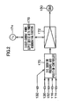
- Figure 1 is a configuration diagram that illustrates a first embodiment of a die cushion apparatus of a press machine according to the present invention;
- Figure 2 is a view that illustrates a first embodiment of a control apparatus in a die cushion apparatus of a press machine according to the present invention;
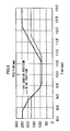
- Figure 3 is a motion diagram that illustrates changes over time in a slide position and a die cushion position;
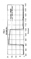
- Figure 4 is a motion diagram that illustrates changes over time in a die cushion pressure command and a die cushion pressure;
- Figure 5 is a view that illustrates a second embodiment of a control apparatus in a die cushion apparatus of a press machine according to the present invention;
- Figure 6 is a view that illustrates a third embodiment of a control apparatus in a die cushion apparatus of a press machine according to the present invention;
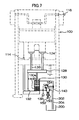
- Figure 7 is a configuration diagram that illustrates a second embodiment of the die cushion apparatus of a press machine according to the present invention;
- Figure 8 is a configuration diagram that illustrates a third embodiment of the die cushion apparatus of a press machine according to the present invention;
- Figure 9 is a configuration diagram that illustrates a fourth embodiment of the die cushion apparatus of a press machine according to the present invention;
- Figure 10 is a configuration diagram that illustrates a fifth embodiment of the die cushion apparatus of a press machine according to the present invention;
- Figure 11 is a view that illustrates a fourth embodiment of a control apparatus in a die cushion apparatus of a press machine according to the present invention;
- Figure 12 is a view that illustrates a fifth embodiment of a control apparatus in a die cushion apparatus of a press machine according to the present invention;
- Figure 13 is a configuration diagram that illustrates a sixth embodiment of the die cushion apparatus of a press machine according to the present invention;
- Figure 14 is a view that illustrates a sixth embodiment of a control apparatus in a die cushion apparatus of a press machine according to the present invention;
- Figure 15 is a view that illustrates a seventh embodiment of a control apparatus in a die cushion apparatus of a press machine according to the present invention;
- Figure 16 is a configuration diagram that illustrates a seventh embodiment of the die cushion apparatus of a press machine according to the present invention;
- Figure 17 is a configuration diagram that illustrates an eighth embodiment of the die cushion apparatus of a press machine according to the present invention;
- Figure 18 is a configuration diagram that illustrates a ninth embodiment of the die cushion apparatus of a press machine according to the present invention;
- Figure 19 is a configuration diagram that illustrates a tenth embodiment of the die cushion apparatus of a press machine according to the present invention;
- Figure 20 is a configuration diagram that illustrates an eleventh embodiment of the die cushion apparatus of a press machine according to the present invention; and
- Figure 21 is a configuration diagram that illustrates a twelfth embodiment of the die cushion apparatus of a press machine according to the present invention.
-
- 100 ... press machine
- 110 ... slide
- 114 ... slide position detector
- 114' ... crank angle detector
- 116 ... crank angular velocity detector
- 120 ... upper die
- 122 ... lower die
- 124 ... crease pressing plate
- 126 ... cushion pin
- 128 ... cushion pad
- 130, 230, 232, 234, 330, 332, 334 ... oil hydraulic cylinder
- 132 ... die cushion position detector
- 134, 160, 202, 204, 220, 222 ... piping
- 136, 136a, 136b ... pressure detector
- 140, 140a, 140b, 140c, 140d ... oil hydraulic pump/motor
- 150, 150a, 150b, 150c, 150d ... electric (servo) motor
- 152, 152a, 152b, 152c, 152d ... motor angular velocity detector
- 162, 262 ... accumulator
- 164, 216, 216a, 216b ... relief valve
- 166, 214, 214a, 214b, 266a, 266b, 274a, 274b ... check valve
- 170, 170a, 170b, 170c ... die cushion pressure and position controller
- 172, 172a, 172b, 172c, 172d ... amplifier and PWM controller
- 174 ... alternating-current power supply
- 176 ... direct-current power supply device with power regeneration function
- 180, 182, 182a, 182b, 182c ... die cushion pressure controller
- 200 ... tank
- 210 ... electric (induction) motor
- 212, 212a, 212b ... oil hydraulic pump
- 280, 280a, 280b ... pressure source
- Hereunder, preferable embodiments of a die cushion apparatus of a press machine according to the present invention will be described in detail in accordance with the attached drawings.
- Figure 1 is a configuration diagram that illustrates a first embodiment of a die cushion apparatus of a press machine according to the present invention.
- In a
press machine 100 shown in Figure 1, a frame is composed by abed 102,columns 104 and crowns 106. Aslide 110 is guided in a freely movable condition in the vertical direction byguide portions 108 that are provided in thecolumns 104. Theslide 110 is moved in the upward and downward directions in Figure 1 by a crank mechanism including acrankshaft 112 to which a rotational driving force is transferred by unshown driving device. - On the
bed 102 side of thepress machine 100 is provided aslide position detector 114 that detects the position of theslide 110. A crankangular velocity detector 116 that detects the angular velocity of thecrankshaft 112 is provided in thecrankshaft 112. - An
upper die 120 is mounted in theslide 110, and alower die 122 is mounted (on a bolster) on thebed 102. - A
crease pressing plate 124 is provided between theupper die 120 and thelower die 122. The underside thereof is supported by acushion pad 128 through a plurality of cushion pins 126, and a material is placed (contacts) on the top side. - The die cushion apparatus principally comprises an oil
hydraulic cylinder 130 that supports theaforementioned cushion pad 128, an oil hydraulic pump/motor 140, an electric (servo)motor 150, and a control apparatus, described later, and the like. - The
cushion pad 128 is supported by the oilhydraulic cylinder 130. A diecushion position detector 132 that detects a position of thecushion pad 128 is disposed in the cushion pad 128 (or a section that links to the oil hydraulic cylinder and a piston). - A piping 134 that connects to a
pressure chamber 130b on the cushion pressure production side (hereunder referred to as "lower chamber") of the oilhydraulic cylinder 130 is connected to apressure detector 136 that detects the pressure of thelower chamber 130b, and is also connected to one discharge opening of an oil hydraulic pump/motor 140. - A piping 160 that connects to a
pressure chamber 130a on a descent side (hereunder referred to as "upper chamber") of the oilhydraulic cylinder 130 is connected to another discharge opening of the oil hydraulic pump/motor 140, and is also connected to anaccumulator 162. - Further, a
relief valve 164 is connected to the piping 134 that is connected to thelower chamber 130b of the oilhydraulic cylinder 130, and a low pressure line (return line) of therelief valve 164 connects to theaccumulator 162. Acheck valve 166 is provided on piping that connects theupper chamber 130a and thelower chamber 130b of the oilhydraulic cylinder 130. - A drive shaft of an
electric motor 150 is connected directly or through a reduction gear to a rotating shaft of the oil hydraulic pump/motor 140. A motorangular velocity detector 152 for detecting the rotational angular velocity of theelectric motor 150 is provided at theelectric motor 150. - Since the die cushion pressure can be expressed by the product of the cylinder area and pressure of the
lower chamber 130b of the oilhydraulic cylinder 130, controlling the die cushion pressure device controlling the pressure of thelower chamber 130b of the oilhydraulic cylinder 130. - In this case, static behavior can be expressed by formulas (1) and (2) below, where:
- Oil hydraulic cylinder and die cushion pressure generation side sectional area: A
- Oil hydraulic cylinder and die cushion pressure generation side volume: V
- Die cushion pressure: P
- Electric (servo) motor torque: T
- Moment of inertia of electric motor: I
- Viscous drag coefficient of electric motor: DM
- Frictional torque of electric motor: fM
- Displacement volume of oil hydraulic pump/motor: Q
- Force applied to oil hydraulic cylinder piston rod from slide: F
- Pad velocity generated upon pressing by press: v
- Inertial mass of pad + oil hydraulic cylinder piston rod: M
- Viscous drag coefficient of oil hydraulic cylinder: DS
- Frictional force of oil hydraulic cylinder: fS
- Angular velocity of servo motor that rotates upon pushing by pressure oil: ω
- Bulk modulus of hydraulic oil: K
- Proportionality factor: k1, k2


- Further, dynamic behavior can be expressed by formulas (3) and (4) in addition to formulas (1) and (2).


- The force represented by the above formulas (1) to (4), that is, the force transferred to the oil
hydraulic cylinder 130 through thecushion pad 128 from theslide 110, compresses thelower chamber 130b of the oilhydraulic cylinder 130 to generate the die cushion pressure. At the same time, the oil hydraulic pump/motor 140 is caused to effect an oil hydraulic motor action by the die cushion pressure and, in a state in which a rotating shaft torque that is generated at the oil hydraulic pump/motor 140 overcomes the drive torque of theelectric motor 150, rotates (regenerative action) theelectric motor 150 to thereby control a rise in pressure. Ultimately, the die cushion pressure is determined in accordance with the drive torque of theelectric motor 150. - Figure 2 is a view that illustrates a first embodiment of a control apparatus in a die cushion apparatus of a press machine according to the present invention. Figure 2 illustrates a control apparatus that is applied to the die cushion apparatus of the first embodiment.
- This control apparatus chiefly comprises a die cushion pressure and
position controller 170, an amplifier andPWM controller 172, an alternating-current power supply 174, and a direct-current power supply device with power regeneration function 176. - The die cushion pressure and
position controller 170 respectively receives a pressure detection signal indicating a pressure P from thepressure detector 136, an angular velocity signal indicating a motor angular velocity ω from the motorangular velocity detector 152, an angular velocity signal indicating a crank angular velocity from the crankangular velocity detector 116, a position detection signal indicating a slide position from theslide position detector 114 and a position detection signal indicating a die cushion position from the diecushion position detector 132, that are shown in Figure 1. - The die cushion pressure and
position controller 170 includes a die cushion pressure command device that outputs a preset die cushion pressure command, and receives the pressure detection signal indicating the pressure P from thepressure detector 136 in order to control the die cushion pressure P in accordance with the die cushion pressure command. - The die cushion pressure and
position controller 170 mainly receives the angular velocity signal indicating the motor angular velocity ω from the motorangular velocity detector 152 as an angular velocity feedback signal for ensuring the dynamic stability of the die cushion pressure, and receives the angular velocity signal indicating the crank angular velocity detected from the crankangular velocity detector 116 for use in compensation for ensuring dynamic stability in die cushion pressure control. In this connection, a configuration may also be adopted in which a slide speed signal indicating a slide speed v that is obtained by subjecting a detected positional signal from theslide position detector 114 to temporal differentiation is used in place of the crank angular velocity signal. - Further, the die cushion pressure and
position controller 170 receives a slide position signal that is input from theslide position detector 114 in order to obtain the start timing of the die cushion function, and the die cushion pressure command device inside the die cushion pressure andposition controller 170 outputs a corresponding die cushion pressure command on the basis of this input slide position signal. The die cushion pressure andposition controller 170 also receives a position detection signal that indicates a die cushion position that is input from the diecushion position detector 132 as a position feedback signal in a case in which the oilhydraulic cylinder 130 is raised or lowered alone or when performing a product knockout operation. - Figure 3 is a motion diagram that illustrates changes over time in a slide position and a die cushion position. Figure 4 is a motion diagram that illustrates changes over time in a die cushion pressure command and a die cushion pressure.
- In Figure 3, when the
slide 110 is in the vicinity of the top dead center (in Figure 3: 250 mm), the cushion pad 128 (crease pressing plate 124) is already standing by at the initial position (in Figure 3: 180 mm). More specifically, the die cushion pressure andposition controller 170 controls (holds) a position by outputting a torque command value that is calculated using a position detection signal of the diecushion position detector 132 and a standby position command value to theelectric motor 150. In this state, the die cushion pressure is substantially 0 (only the amount of a pre-applied pressure acts) as shown in Figure 4. - When the
slide 110 descends and a position detection signal of theslide position detector 114 reaches the (vicinity of the) die cushion initial position, the die cushion pressure andposition controller 170 switches the control from a position (holding) control state to a die cushion pressure control state. More specifically, the die cushion pressure andposition controller 170 carries out die cushion pressure control by outputting a torque command value that is calculated using a die cushion pressure command value, a pressure detection signal, and a motor angular velocity signal (press velocity signal) to theelectric motor 150 through the amplifier andPWM controller 172. - Further, when performing die cushion pressure control, the torque output direction of the
electric motor 150 and the generated velocity are opposite at the descending time (formation time) from the time that theslide 110 collides with the material (and crease pressing plate 124) until it reaches the bottom dead center. More specifically, the motive power that is received by thecushion pad 128 from theslide 110 causes pressure oil from thelower chamber 130b of the oilhydraulic cylinder 130 to flow into the oil hydraulic pump/motor 140, whereby the oil hydraulic pump/motor 140 acts as an oil hydraulic motor. Theelectric motor 150 is driven by the oil hydraulic pump/motor 140 and acts as a power generator. Power that is generated by theelectric motor 150 is regenerated in the alternating-current power supply 174 via the amplifier andPWM controller 172 and the direct-current power supply device with power regeneration function 176. - As shown in Figure 1, with respect to the die (
upper die 120 and lower die 122) according to the present example, a die is mounted that is used for processing items having the shape of a hollow cup that is closed at the top (draw shape). - The
slide 110 descends in a state in which a material (in this example, a circular plate) is placed on thecrease pressing plate 124 that is standing by in a condition in which it is supported by thecushion pin 126 at a predetermined initial position. At the point in time when theupper die 120 contacts against the material, press working (drawing) of the material begins. The material undergoes plastic working between theupper die 120 and thelower die 122, and at the same time is supported from below through thecushion pin 126 and thecrease pressing plate 124 with a set (pressure) force that is necessary for controlling cracks or wrinkles that are generated in the radial direction of the circular material that are liable to occur at the time of drawing. The force at this time is the die cushion pressure, and this die cushion pressure always acts during the working. - Generally, in the case of circular draw forming, since the area of a flat material portion decreases as the drawing progresses (cylinder lengthens), it is sufficient that the die cushion pressure is small. Using a small pressure (securing the necessary minimum pressure) improves the formability since it is difficult to break the material and the material is deeply drawn.
- The reason that variability of a die cushion pressure (variable pressure) is required during a press-formation process is to improve the formability as described above.
- In this connection, since a slide collides (strikes in an impacting manner) against the material (and crease pressing plate) when the working process starts, an impact force (a surge pressure in the case of an oil hydraulic cylinder) is easily generated at the die cushion and that impact force exceeds a predetermined die cushion pressure and therefore may break a molded article or damage the die and adversely affect the endurance life of the machine itself.
- As described above, in a die cushion apparatus of a press machine according to the present invention, pressure is produced in the oil
hydraulic cylinder 130 by the motive power of theslide 110 through the die, thecrease pressing plate 124, thecushion pin 126, and thecushion pad 128. This pressure (die cushion pressure) is controlled so as to be a die cushion pressure command value by controlling the torque of theelectric motor 150 based on a die cushion pressure command and a pressure detection signal detected by thepressure detector 136. Further, when theslide 110 descends (formation time), regeneration (to the power source) of motive power is performed by theelectric motor 150 that is driven by causing the oil hydraulic pump/motor 140 to act as an oil hydraulic motor using pressure oil that is discharged from thelower chamber 130b of the oilhydraulic cylinder 130. - At the time of the above described torque control of the
electric motor 150, an angular velocity signal that is detected by the motorangular velocity detector 152 is used for the purpose of ensuring dynamic stability with respect to control of the die cushion pressure. A position detection signal detected by the diecushion position detector 132 is used for the purpose of (a position feedback signal in) positional control in a case in which an oil hydraulic cylinder is raised or lowered alone or when performing a product knockout operation. - In Figure 1, the
accumulator 162 is filled with a substantially constant low pressure oil of a pressure of approximately 0.5 to 1 Mpa. As well as serving the function of a tank, theaccumulator 162 also fulfills the function of supplying the substantially constant low pressure oil to thelower chamber 130b of the oilhydraulic cylinder 130 through thecheck valve 166 to perform pre-pressurization to facilitate pressurization when performing die cushion pressure control. - The
relief valve 164 is provided to prevent damage to the hydraulic equipment when an abnormal pressure occurs (when die cushion pressure control is not possible, and a sudden abnormal pressure occurs). - A position detection signal that is detected by the
slide position detector 114 is used for controlling the start (start of pressure control) timing of the die cushion function. An angular velocity signal that is detected by the crankangular velocity detector 116 is used for ensuring dynamic stability in control of the die cushion pressure. - Further, a die cushion pressure command value in the case of the present example drops in a tapered shape as shown in Figure 4. As described in the foregoing, this is because the required crease pressing force decreases in proportion to the draw-forming depth during drawing.
- Control of the die cushion pressure continues during a halt after the
slide 110 reaches the bottom dead center. At a time (near) when theslide 110 starts to ascend (at approximately 10.5 seconds in Figure 3), control of the die cushion pressure ends and the control is switched to die cushion position control. According to the present embodiment, after a fixed time from when theslide 110 starts to ascend thecushion pad 128 is raised and returned to the initial position to prepare for the next cycle. - Figure 5 is a view that illustrates a second embodiment of a control apparatus for the die cushion apparatus of a press machine according to the present invention. The parts common with parts of the control apparatus according to the first embodiment as illustrated in Figure 2 are assigned the same reference numerals and detailed explanations thereof are omitted.
- In comparison to the control apparatus according to the first embodiment as illustrated in Figure 2, the control apparatus according to the second embodiment illustrated in Figure 5 is different in the respect that a die
cushion pressure controller 180 is provided in place of the die cushion pressure andposition controller 170. - The die
cushion pressure controller 180 differs from the die cushion pressure andposition controller 170 in the respect that a position detection signal from the diecushion position detector 132 is not input to the diecushion pressure controller 180 and the diecushion pressure controller 180 does not perform positional control of thecushion pad 128. - In this connection, the
cushion pad 128 can be moved so that thecushion pad 128 stands by in a desired standby position by raising thecushion pad 128 by controlling the velocity of theelectric motor 150 using the angular velocity signal to mechanically cause thecushion pad 128 to contact against an unshown stopper, and obtaining verification with a limit switch or the like. - Figure 6 is a view that illustrates a third embodiment of a control apparatus for the die cushion apparatus of a press machine according to the present invention. The parts common with parts of the control apparatus according to the second embodiment as illustrated in Figure 5 are assigned the same reference numerals and detailed explanations thereof are omitted.
- In comparison to the control apparatus according to the second embodiment as illustrated in Figure 5, the control apparatus according to the third embodiment illustrated in Figure 6 is different in the respect that a die
cushion pressure controller 182 is provided in place of the diecushion pressure controller 180. - Only a pressure detection signal that is detected by the
pressure detector 136 is input to the diecushion pressure controller 182. - The die
cushion pressure controller 182 conducts die cushion pressure control by outputting a torque command value that is calculated using a predetermined die cushion pressure command value (fixed value) and a pressure detection signal that is input by thepressure detector 136 to theelectric motor 150 through the amplifier andPWM controller 172. In this case, thecushion pad 128 after completion of forming is raised by performing low torque control for theelectric motor 150 to allow thecushion pad 128 to standby in a state in which it contacts against a stopper. - Figure 7 is a configuration diagram that illustrates the second embodiment of a die cushion apparatus of a press machine according to the present invention. The parts common with parts of the die cushion apparatus of the first embodiment as illustrated in Figure 1 are assigned the same reference numerals and detailed explanations thereof are omitted.
- In comparison to the die cushion apparatus of a press machine of the first embodiment as illustrated in Figure 1, the die cushion apparatus of the second embodiment illustrated in Figure 7 is different in the respect that a
tank 200 is provided and theaccumulator 162 orcheck valve 166 is not provided. - Another discharge opening of the oil hydraulic pump/
motor 140 is connected to thetank 200 through thepiping 202. Further, theupper chamber 130a of the oilhydraulic cylinder 130 and the low pressure line of therelief valve 164 connect to thetank 200 through thepiping 204. - The die cushion apparatus of a press machine according to this second embodiment cannot pre-pressurize the
upper chamber 130a andlower chamber 130b of the oilhydraulic cylinder 130 using a substantially constant low pressure oil. - Figure 8 is a configuration diagram that illustrates the third embodiment of a die cushion apparatus of a press machine according to the present invention. The parts common with parts of the die cushion apparatus of the second embodiment as illustrated in Figure 7 are assigned the same reference numerals and detailed explanations thereof are omitted.
- In comparison to the die cushion apparatus of a press machine according to the second embodiment as illustrated in Figure 7, the die cushion apparatus according to the third embodiment illustrated in Figure 8 is different in the respect that an oil
hydraulic pump 212 that is driven by an electric (induction)motor 210, acheck valve 214, and arelief valve 216 are added. - A discharge opening of the oil
hydraulic pump 212 is connected to thelower chamber 130b of the oilhydraulic cylinder 130 through thecheck valve 214. Accordingly, by driving the oilhydraulic pump 212 using theelectric motor 210, pressure oil can be supplied to thelower chamber 130b of the oilhydraulic cylinder 130 by a separate system to the oil hydraulic pump/motor 140. - According to the present example, the pressure of the
lower chamber 130b of the oilhydraulic cylinder 130 is kept in a low pressure state that is slightly higher than the atmospheric pressure, and thus problems such as the intake of air do not occur. - The control apparatus according to the first embodiment as shown in Figure 2 can be applied as the control apparatus of the die cushion apparatus of the second and third embodiments that are described above.
- Figure 9 is a configuration diagram that illustrates the fourth embodiment of a die cushion apparatus of a press machine according to the present invention. The parts common with parts of the die cushion apparatus of the first embodiment as illustrated in Figure 1 are assigned the same reference numerals and detailed explanations thereof are omitted.
- In comparison to the die cushion apparatus of a press machine according to the first embodiment as illustrated in Figure 1, the die cushion apparatus according to the fourth embodiment illustrated in Figure 9 is different in the respect that the
cushion pad 128 is supported by a plurality of oilhydraulic cylinders - The respective
lower chambers hydraulic cylinders motor 140. The respectiveupper chambers hydraulic cylinders accumulator 164 side) of the oil hydraulic pump/motor 140. - By using the plurality of oil
hydraulic cylinders cushion pad 128. - Figure 10 is a configuration diagram that illustrates the fifth embodiment of a die cushion apparatus of a press machine according to the present invention. The parts common with parts of the die cushion apparatus of the fourth embodiment as illustrated in Figure 9 are assigned the same reference numerals and detailed explanations thereof are omitted.
- In comparison to the die cushion apparatus of a press machine according to the fourth embodiment as illustrated in Figure 9, the die cushion apparatus according to the fifth embodiment illustrated in Figure 10 is different in the respect that a plurality of sets (four sets in this example) of oil hydraulic pump/
motors 140a to 140d,electric motors 150a to 150d, and motorangular velocity detectors 152a to 152d are provided. - One of the discharge openings of each of the oil hydraulic pump/
motors 140a to 140d is commonly connected to the piping 134 that connects to the respectivelower chambers hydraulic cylinders accumulator 164 side) of each of the oil hydraulic pump/motors 140a to 140d is commonly connected to the piping 160 that connects to the respectiveupper chambers hydraulic cylinders - The reason for providing a plurality of sets of oil hydraulic pump/
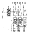
motors 140a to 140d andelectric motors 150a to 150d in this manner is that there is a limit to the displacement volume of pressure oil of oil hydraulic pump/motors or the output torque of electric motors that are commercially available. - Figure 11 is a view that illustrates a fourth embodiment of a control apparatus for the die cushion apparatus of a press machine according to the present invention, and shows a control apparatus that can be applied to the die cushion apparatus according to the fifth embodiment as shown in Figure 10. The parts common with parts of the control apparatus according to the first embodiment as illustrated in Figure 2 are assigned the same reference numerals and detailed explanations thereof are omitted.
- In comparison to the control apparatus according to the first embodiment as illustrated in Figure 2, the control apparatus according to the fourth embodiment illustrated in Figure 11 is different in the respect that amplifier and
PWM controllers 172a to 172d are provided for each of theelectric motors 150a to 150d. - The die cushion pressure and
position controller 170 conducts die cushion pressure control by outputting a torque command value that is calculated using a die cushion pressure command value, a pressure detection signal, and a motor angular velocity signal (press velocity signal) to theelectric motors 150a to 150d through the amplifier andPWM controllers 172a to 172d. - In this connection, although the oil hydraulic pump/
motors 140a to 140d that are respectively driven by theelectric motors 150a to 150d basically generate the same torque, in order to ensure dynamic stability when performing die cushion pressure control and positional control, the die cushion pressure andposition controller 170 receives respective angular velocity detection signals that are input from the motorangular velocity detectors 152a to 152 of theelectric motors 150a to 150d. - Figure 12 is a view that illustrates a fifth embodiment of a control apparatus for the die cushion apparatus of a press machine according to the present invention, and shows a control apparatus that can be applied to the die cushion apparatus according to the fifth embodiment as shown in Figure 10. The parts common with parts of the control apparatus according to the third embodiment as illustrated in Figure 6 are assigned the same reference numerals and detailed explanations thereof are omitted.
- In comparison to the control apparatus according to the third embodiment as illustrated in Figure 6, the control apparatus according to the fourth embodiment illustrated in Figure 12 is different in the respect that amplifier and
PWM controllers 172a to 172d are provided for each of theelectric motors 150a to 150d. - Figure 13 is a configuration diagram that illustrates the sixth embodiment of the die cushion apparatus of a press machine according to the present invention. The parts common with parts of the die cushion apparatus of the fifth embodiment as illustrated in Figure 10 are assigned the same reference numerals and detailed explanations thereof are omitted.
- In comparison to the die cushion apparatus of a press machine of the fifth embodiment as illustrated in Figure 10, the die cushion apparatus of the sixth embodiment illustrated in Figure 13 is different in the respect that hydraulic circuits (hydraulic circuits including oil hydraulic pump/
motors 140a to 140c,accumulators 162a to 162c,relief valves 164a to 164c, andcheck valves 166a to 166c) are independently provided for each of the oilhydraulic cylinders - Accordingly, the pressures of the
lower chambers hydraulic cylinders pressure detectors - In the case of the die cushion apparatus according to this configuration, each oil
hydraulic cylinder cushion pad 128, a die cushion pressure can be produced in accordance with the eccentric load. - Figure 14 is a view that illustrates a sixth embodiment of a control apparatus for a die cushion apparatus of a press machine according to the present invention, and shows a control apparatus that can be applied to the die cushion apparatus of the sixth embodiment as shown in Figure 13. The parts common with parts of the control apparatus according to the first embodiment as illustrated in Figure 2 are assigned the same reference numerals and detailed explanations thereof are omitted.
- In comparison to the control apparatus according to the first embodiment as illustrated in Figure 2, the control apparatus according to the sixth embodiment illustrated in Figure 14 is different in the respect that die cushion pressure and
position controllers 170a to 170c and amplifier andPWM controllers 172a to 172c are provided for each of theelectric motors 150a to 150c. - Each of the die cushion pressure and
position controllers 170a to 170c receives respective pressure detection signals that are respectively input from thepressure detectors 136a to 136c and also receives respective angular velocity signals that are respectively input from the motorangular velocity detectors 152a to 152c. Each of the die cushion pressure andposition controllers 170a to 170c also receives the same crank angular velocity signal, slide position detection signal, and die cushion position detection signal from the crankangular velocity detector 116, theslide position detector 114, and the diecushion position detector 132, respectively. - Each of the die cushion pressure and
position controllers 170a to 170c calculates respective torque command values based on the above described input signals, and perform die cushion pressure control by outputting these torque command values to theelectric motors 150a to 150c through the amplifier andPWM controllers 172a to 172c. - Figure 15 is a view that illustrates a seventh embodiment of a control apparatus for a die cushion apparatus of a press machine according to the present invention, and shows a control apparatus that can be applied to the die cushion apparatus of the sixth embodiment as shown in Figure 13. The parts common with parts of the control apparatus according to the third embodiment as illustrated in Figure 6 are assigned the same reference numerals and detailed explanations thereof are omitted.
- In comparison to the control apparatus according to the third embodiment as illustrated in Figure 6, the control apparatus according to the seventh embodiment illustrated in Figure 15 is different in the respect that die
cushion pressure controllers 182a to 182c and amplifier andPWM controllers 172a to 172c are provided for each of theelectric motors 150a to 150c. - Each of the die
cushion pressure controllers 182a to 182c receives respective pressure detection signals that are respectively input from thepressure detectors 136a to 136c, and performs die cushion pressure control by outputting torque command values that are respectively calculated using a predetermined die cushion pressure command value and pressure detection signals that are input from thepressure detectors 136a to 136c to theelectric motors 150a to 150c through the amplifier andPWM controllers 172a to 172c. - Figure 16 is a configuration diagram that illustrates the seventh embodiment of the die cushion apparatus of a press machine according to the present invention. The parts common with parts of the die cushion apparatus of the fourth embodiment as illustrated in Figure 9 are assigned the same reference numerals and detailed explanations thereof are omitted.
- In comparison to the die cushion apparatus of a press machine according to the fourth embodiment as illustrated in Figure 9, the die cushion apparatus according to the seventh embodiment illustrated in Figure 16 differs mainly in the respect that the other discharge opening of the oil hydraulic pump/
motor 140 connects to theupper chambers hydraulic cylinders common piping 160 without directly communicating with an accumulator (or tank). - It is thereby possible to control a downward movement of the oil
hydraulic cylinders - Further, two
check valves piping 160, and arelief valve 164 is connected to the piping 220 between thesecheck valves check valves single relief valve 164. - Two pilot-opening
type check valves piping 160, and anaccumulator 262 is connected to the piping 222 between these pilot-openingtype check valves - Electromagnetic
direction switching valves type check valves accumulator 262 are applied thereto. - In the present example, when executing a die cushion function or an independent raising operation, the pilot-opening
type check valve 270a is closed (allowing a low pressure from theaccumulator 262 to act) by exciting (turning on) the electromagneticdirection switching valve 272a and the pilot-openingtype check valve 270b is opened (causing a die cushion pressure or a drive pressure to effect a pilot action) by non-excitation of (turning off) the electromagneticdirection switching valve 272b. In contrast, when performing an independent descent operation, the pilot-openingtype check valve 270b is closed by turning on the electromagneticdirection switching valve 272b and the pilot-openingtype check valve 270a is opened by turning off the electromagneticdirection switching valve 272a. - The reason for opening and closing the pilot-opening
type check valves upper chambers lower chambers hydraulic cylinders accumulator 262 to balance the different oil amounts. In this connection, it is possible to supply the substantially constant low pressure oil that is filled in theaccumulator 162 to theupper chambers lower chambers hydraulic cylinders type check valves - Figure 17 is a configuration diagram that illustrates the eighth embodiment of the die cushion apparatus of a press machine according to the present invention. The parts common with parts of the die cushion apparatus of the seventh embodiment as illustrated in Figure 16 are assigned the same reference numerals and detailed explanations thereof are omitted.
- In comparison to the die cushion apparatus of a press machine according to the seventh embodiment as illustrated in Figure 16, the die cushion apparatus according to the eighth embodiment illustrated in Figure 17 differs mainly in the respect that double-rod type oil
hydraulic cylinders hydraulic cylinders check valves type check valves slide position detector 114. - The
check valves upper chambers lower chambers hydraulic cylinders accumulator 162 to fulfill a role of performing pre-pressurizing to facilitate pressurization when performing die cushion pressure control. - Further, in the oil
hydraulic cylinders upper chambers lower chambers hydraulic cylinders type check valves - Figure 18 is a configuration diagram that illustrates the ninth embodiment of the die cushion apparatus of a press machine according to the present invention. The parts common with parts of the die cushion apparatus of the seventh embodiment as illustrated in Figure 16 are assigned the same reference numerals and detailed explanations thereof are omitted.
- In comparison to the die cushion apparatus of a press machine according to the seventh embodiment as illustrated in Figure 16, the die cushion apparatus according to the ninth embodiment illustrated in Figure 18 differs in the respect that while the die cushion apparatus according to the seventh embodiment has a plurality of oil
hydraulic cylinders 230 to 234 and one set of an oil hydraulic pump/motor 140 and anelectric motor 150, the die cushion apparatus according to the ninth embodiment comprises a single oilhydraulic cylinder 130 and a plurality of sets (two sets) of oil hydraulic pump/motors electric motors hydraulic cylinder 130. - Figure 19 is a configuration diagram that illustrates the tenth embodiment of the die cushion apparatus of a press machine according to the present invention. The parts common with parts of the die cushion apparatus of the ninth embodiment as illustrated in Figure 18 are assigned the same reference numerals and detailed explanations thereof are omitted.
- In comparison to the die cushion apparatus of a press machine according to the ninth embodiment as illustrated in Figure 18, the die cushion apparatus according to the tenth embodiment illustrated in Figure 19 differs in the respect that it comprises a
separate pressure source 280 that produces a pilot pressure. - The
pressure source 280 comprises an electric (induction)motor 210, an oilhydraulic pump 212, acheck valve 214, and arelief valve 216. Thecheck valve 214 is provided to stabilize the discharge of the oilhydraulic pump 212 that is driven with theelectric motor 210, and therelief valve 216 is used for regulating the pilot pressure. - By enabling a pilot pressure to be supplied from the
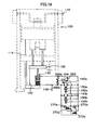
pressure source 280 of the above described configuration to the pilot-openingtype check valves type check valves accumulator 262. In the case of the present example, by turning off the electromagneticdirection switching valves pressure source 280 can be applied to the pilot-openingtype check valves - Figure 20 is a configuration diagram that illustrates the eleventh embodiment of the die cushion apparatus of a press machine according to the present invention. The parts common with parts of the die cushion apparatus of the eighth embodiment as illustrated in Figure 17 are assigned the same reference numerals and detailed explanations thereof are omitted.
- In comparison to the die cushion apparatus of a press machine according to the eighth embodiment as illustrated in Figure 17, the die cushion apparatus according to the eleventh embodiment illustrated in Figure 20 differs in the respect that while the die cushion apparatus according to the eighth embodiment employs the
accumulator 262 as a pressure source that pre-pressurizes theupper chambers lower chambers hydraulic cylinders separate pressure source 280 that pre-pressurizes theupper chambers lower chambers hydraulic cylinders tank 200 is provided in place of theaccumulator 262. - The
pressure source 280 comprises the electric (induction)motor 210, the oilhydraulic pump 212, thecheck valve 214, and therelief valve 216, and supplies pressure oil for pre-pressurization to the piping 222 between the twocheck valves - Further, two
pressure detectors lower chambers hydraulic cylinders pressure detectors - Figure 21 is a configuration diagram that illustrates the twelfth embodiment of the die cushion apparatus of a press machine according to the present invention. The parts common with parts of the die cushion apparatus of the seventh embodiment as illustrated in Figure 16 are assigned the same reference numerals and detailed explanations thereof are omitted.
- In comparison to the die cushion apparatus of a press machine according to the seventh embodiment as illustrated in Figure 16, the die cushion apparatus according to the twelfth embodiment illustrated in Figure 21 differs in the respect that while the die cushion apparatus according to the seventh embodiment employs the
accumulator 262 as a pressure source that pre-pressurizes theupper chambers lower chambers hydraulic cylinders separate pressure source 280a that pre-pressurizes theupper chambers lower chambers hydraulic cylinders separate pressure source 280b that produces a pilot pressure that is applied to the pilot-openingtype check valves - According to the twelfth embodiment the
tank 200 is provided in place of theaccumulator 262, and twopressure detectors lower chambers hydraulic cylinders - The
pressure source 280a comprises the electric (induction)motor 210, an oilhydraulic pump 212a, acheck valve 214a, and arelief valve 216a, and supplies pressure oil for pre-pressurization to the piping 222 between the twocheck valves - Further, the
pressure source 280b comprises theelectric motor 210, an oilhydraulic pump 212b, acheck valve 214b, and arelief valve 216b, and supplies a required pilot pressure to the pilot-openingtype check valves - In the case of the present example, by turning off the electromagnetic
direction switching valves pressure source 280b can be applied to the pilot-openingtype check valves type check valves - It is to be understood that although the die cushion apparatuses according to the first to twelfth embodiments were described using oil as a hydraulic fluid, the present invention is not limited thereto, and water or another fluid may also be used. Further, the die cushion apparatus according to the present invention is not limited to a clamp press, and can also be applied to a press machine such as another mechanical press, an electric (servo) press, and a hydraulic press.
Claims (15)
- A die cushion apparatus of a press machine, comprising:a fluid hydraulic cylinder that supports a cushion pad;a pressure detector that detects a pressure of a pressure chamber on a cushion pressure production side of the fluid hydraulic cylinder;a fluid hydraulic pump/motor having a discharge opening that is connected through a first pipe to the pressure chamber on a cushion pressure production side of the fluid hydraulic cylinder;an electric motor that is connected to a rotating shaft of the fluid hydraulic pump/motor;a die cushion pressure command device that outputs a die cushion pressure command that is previously set;a control device that controls a torque of the electric motor so that a die cushion pressure is a pressure that corresponds to the die cushion pressure command based on the die cushion pressure command and a pressure that is detected by the pressure detector; anda regeneration device that regenerates energy required for a die cushioning action that the cushion pad receives when die cushioning of the press machine is effected as electrical energy through the fluid hydraulic cylinder, the fluid hydraulic pump/motor, and the electric motor.
- The die cushion apparatus of a press machine according to claim 1, wherein
a plurality of the fluid hydraulic cylinders that support the cushion pad are provided, and respective pressure chambers on a cushion pressure production side of each fluid hydraulic cylinder are commonly connected to the first pipe. - The die cushion apparatus of a press machine according to claim 1 or 2, wherein
a plurality of sets of the fluid hydraulic pump/motor and the electric motor are provided, and respective discharge openings of the plurality of fluid hydraulic pump/motors are commonly connected to the first pipe. - A die cushion apparatus of a press machine, comprising:a plurality of fluid hydraulic cylinders that support a cushion pad;a plurality of pressure detectors that detect a pressure of a pressure chamber on a cushion pressure production side of each fluid hydraulic cylinder, respectively;a plurality of fluid hydraulic pump/motors having a discharge opening that is connected through a first pipe to a pressure chamber on the cushion pressure production side of each fluid hydraulic cylinder;a plurality of electric motors that are respectively connected to a rotating shaft of each fluid hydraulic pump/motor;a die cushion pressure command device that outputs a die cushion pressure command that is previously set;a control device that controls a torque of each electric motor so that a die cushion pressure is a pressure that corresponds to the die cushion pressure command based on the die cushion pressure command and pressures that are detected by the plurality of pressure detectors; anda regeneration device that regenerates energy required for a die cushioning action that the cushion pad receives when die cushioning of a press machine is effected as electrical energy through the plurality of fluid hydraulic cylinders, fluid hydraulic pump/motors and electric motors.
- The die cushion apparatus of a press machine according to any one of claims 1 to 4, wherein
an other discharge opening of the fluid hydraulic pump/motor is connected to a pressure chamber on a descent side of the fluid hydraulic cylinder through a second pipe, and the second pipe is connected with an accumulator that is filled with a liquid of a substantially constant low pressure. - The die cushion apparatus of a press machine according to any one of claims 1 to 4, wherein
an other discharge opening of the fluid hydraulic pump/motor is connected to a tank through a second pipe. - The die cushion apparatus of a press machine according to any one of claims 1 to 4, wherein
an other discharge opening of the fluid hydraulic pump/motor is connected to a pressure chamber on a descent side of the fluid hydraulic cylinder through a second pipe without directly communicating with a substantially constant low pressure source comprising a tank or an accumulator. - The die cushion apparatus of a press machine according to any one of claims 1 to 6, wherein
a relief valve is connected to the first pipe such that an abnormal pressure that is produced in a pressure chamber on the cushion pressure production side of the fluid hydraulic cylinder is released through the relief valve. - The die cushion apparatus of a press machine according to claim 7, wherein
two check valves are provided in mutually opposite directions in a third pipe that connects a first pipe that is connected to a pressure chamber on the cushion pressure production side of the fluid hydraulic cylinder and a second pipe that is connected to a pressure chamber on a descent side of the fluid hydraulic cylinder, and
a relief valve is connected to the third pipe between the two check valves such that an abnormal pressure that is produced in a pressure chamber on the cushion pressure production side or a pressure chamber on a descent side of the fluid hydraulic cylinder is released through the relief valve. - The die cushion apparatus of a press machine according to claim 8 or 9, further comprising an accumulator that is filled with a liquid of a substantially constant low pressure, wherein
the accumulator is connected to a low pressure line of the relief valve and also connected to two pressure chambers or a pressure chamber on the cushion pressure production side of the fluid hydraulic cylinder through a check valve or a pilot-opening type check valve. - The die cushion apparatus of a press machine according to claim 8 or 9, further comprising a tank that is connected to a low pressure line of the relief valve, wherein
a low pressure liquid is discharged with a liquid pressure pump from the tank through a check valve or a pilot-opening type check valve to two pressure chambers or a pressure chamber on the cushion pressure production side of the fluid hydraulic cylinder. - The die cushion apparatus of a press machine according to any one of claims 1 to 11, further comprising an angular velocity detector for detecting a rotational angular velocity of the electric motor, wherein
the control device uses an angular velocity signal that is detected by the angular velocity detector as an angular velocity feedback signal for ensuring dynamic stability of a die cushion pressure. - The die cushion apparatus of a press machine according to any one of claims 1 to 12, further comprising a die cushion position detector that detects a position of the cushion pad, wherein
the control device uses a die cushion position signal that is detected by the die cushion position detector as a position feedback signal in a case in which a fluid hydraulic cylinder is raised or lowered alone or when performing a product knockout operation. - The die cushion apparatus of a press machine according to any one of claims 1 to 13, further comprising a slide position detector that detects a slide position of the press machine or an angle detector that detects an angle of a drive shaft of the press machine, wherein
the die cushion pressure command device outputs a die cushion pressure command based on a slide position signal that is detected by the slide position detector or an angle signal that is detected by the angle detector. - The die cushion apparatus of a press machine according to any one of claims 1 to 14, further comprising a slide speed detector that detects a sliding speed of the press machine or an angular velocity detector that detects an angular velocity of a drive shaft of the press machine, wherein
the control device uses a slide speed signal that is detected by the slide speed detector or an angular velocity signal that is detected by the angular velocity detector in compensation for ensuring dynamic stability in die cushion pressure control.
Priority Applications (1)
| Application Number | Priority Date | Filing Date | Title |
|---|---|---|---|
| EP14152419.9A EP2724796A1 (en) | 2005-05-16 | 2006-01-17 | Die cushion apparatus for press machine |
Applications Claiming Priority (2)
| Application Number | Priority Date | Filing Date | Title |
|---|---|---|---|
| JP2005143012A JP4576639B2 (en) | 2005-05-16 | 2005-05-16 | Die cushion device for press machine |
| PCT/JP2006/300507 WO2006123452A1 (en) | 2005-05-16 | 2006-01-17 | Die cushion device for press machine |
Related Child Applications (2)
| Application Number | Title | Priority Date | Filing Date |
|---|---|---|---|
| EP14152419.9A Division EP2724796A1 (en) | 2005-05-16 | 2006-01-17 | Die cushion apparatus for press machine |
| EP14152419.9A Division-Into EP2724796A1 (en) | 2005-05-16 | 2006-01-17 | Die cushion apparatus for press machine |
Publications (3)
| Publication Number | Publication Date |
|---|---|
| EP1882534A1 true EP1882534A1 (en) | 2008-01-30 |
| EP1882534A4 EP1882534A4 (en) | 2013-08-14 |
| EP1882534B1 EP1882534B1 (en) | 2014-09-24 |
Family
ID=37431035
Family Applications (2)
| Application Number | Title | Priority Date | Filing Date |
|---|---|---|---|
| EP06711787.9A Revoked EP1882534B1 (en) | 2005-05-16 | 2006-01-17 | Die cushion device for press machine |
| EP14152419.9A Withdrawn EP2724796A1 (en) | 2005-05-16 | 2006-01-17 | Die cushion apparatus for press machine |
Family Applications After (1)
| Application Number | Title | Priority Date | Filing Date |
|---|---|---|---|
| EP14152419.9A Withdrawn EP2724796A1 (en) | 2005-05-16 | 2006-01-17 | Die cushion apparatus for press machine |
Country Status (11)
| Country | Link |
|---|---|
| US (1) | US8037735B2 (en) |
| EP (2) | EP1882534B1 (en) |
| JP (1) | JP4576639B2 (en) |
| KR (1) | KR101247618B1 (en) |
| CN (1) | CN101175585B (en) |
| CA (1) | CA2609056C (en) |
| DE (1) | DE202006021150U1 (en) |
| ES (1) | ES2519691T3 (en) |
| HK (1) | HK1111937A1 (en) |
| TW (1) | TW200640661A (en) |
| WO (1) | WO2006123452A1 (en) |
Cited By (14)
| Publication number | Priority date | Publication date | Assignee | Title |
|---|---|---|---|---|
| CN103273672A (en) * | 2013-06-19 | 2013-09-04 | 张绍宁 | Automatic production system for semi-finished brake pad |
| EP2712688A1 (en) * | 2012-09-28 | 2014-04-02 | Siemens Aktiengesellschaft | Die cushion drive and method for operating a die cushion drive |
| US8757056B2 (en) | 2008-11-18 | 2014-06-24 | Aida Engineering, Ltd. | Die cushion device for press machine |
| CN105057432A (en) * | 2015-08-31 | 2015-11-18 | 西安交通大学 | Hydraulic extension cushion with planetary roller screw driven by alternating-current servo synchronous motor |
| DE102014226634B3 (en) * | 2014-12-19 | 2016-05-12 | Robert Bosch Gmbh | Method for operating a hydraulic drive, computing unit, computer program and machine-readable storage medium |
| FR3036486A1 (en) * | 2015-05-18 | 2016-11-25 | Sagem Defense Securite | METHOD FOR ESTIMATING AN EXTERNAL FORCE EXERCISING AN ELECTROHYDROSTATIC ACTUATOR |
| EP3101281A1 (en) * | 2015-06-05 | 2016-12-07 | Robert Bosch Gmbh | Hydraulic circuit for supplying pressure to a hydraulic consumer in a closed hydraulic circuit |
| EP3115119A1 (en) * | 2015-07-10 | 2017-01-11 | Aida Engineering, Ltd. | Die cushion-cum-slide cushion device and method of controlling the same |
| EP3467307A1 (en) | 2017-10-04 | 2019-04-10 | Automation, Press and Tooling, A.P. & T AB | Pressure control of hydraulic system with electric motor |
| WO2019185362A1 (en) * | 2018-03-27 | 2019-10-03 | Moog Gmbh | Press drive with energy recovery |
| WO2021009285A1 (en) | 2019-07-17 | 2021-01-21 | Moog Gmbh | Device and method for open-loop or closed-loop control of a movement of a die cushion of a die cushion press |
| WO2021028427A1 (en) | 2019-08-15 | 2021-02-18 | Voith Patent Gmbh | Overheating protection for hydraulic systems |
| DE102020201507A1 (en) | 2020-02-07 | 2021-08-12 | Robert Bosch Gesellschaft mit beschränkter Haftung | Method for operating a hydraulic drive |
| EP4015100A1 (en) * | 2020-12-18 | 2022-06-22 | Aida Engineering Ltd. | Die cushion device |
Families Citing this family (61)
| Publication number | Priority date | Publication date | Assignee | Title |
|---|---|---|---|---|
| DE102006058630B4 (en) * | 2006-12-13 | 2012-12-06 | Schuler Pressen Gmbh & Co. Kg | Electro-hydraulic press main or auxiliary drive device, in particular electro-hydraulic die cushion drive |
| KR100841229B1 (en) * | 2007-03-26 | 2008-06-26 | 주식회사 극동이엔지 | Inching unit of press |
| US7823434B2 (en) * | 2007-04-27 | 2010-11-02 | Wilson Tool International Inc. | Live tooling systems for machine tools |
| JP5407129B2 (en) * | 2007-09-11 | 2014-02-05 | 株式会社Ihi | Die cushion device control method and die cushion device |
| JP5466834B2 (en) * | 2008-05-22 | 2014-04-09 | 株式会社小松製作所 | Die cushion device |
| JP5060423B2 (en) * | 2008-08-06 | 2012-10-31 | アイダエンジニアリング株式会社 | Die cushion device for press machine |
| JP4942714B2 (en) * | 2008-08-21 | 2012-05-30 | アイダエンジニアリング株式会社 | Die cushion device for press machine |
| US8348249B2 (en) * | 2008-10-07 | 2013-01-08 | Dadco, Inc. | Reaction device for forming equipment |
| JP5257773B2 (en) * | 2008-11-20 | 2013-08-07 | 株式会社Ihi | Die cushion device for press machine |
| JP5446743B2 (en) * | 2009-11-05 | 2014-03-19 | 株式会社Ihi | Control device and method for die cushion device |
| JP5418154B2 (en) * | 2009-11-05 | 2014-02-19 | 株式会社Ihi | Control device and method for die cushion device |
| KR101347461B1 (en) * | 2010-05-18 | 2014-01-02 | 미쓰비시덴키 가부시키가이샤 | Motor control device |
| CN102893514B (en) * | 2010-05-18 | 2015-10-14 | 三菱电机株式会社 | Controller for motor |
| WO2012008222A1 (en) * | 2010-07-14 | 2012-01-19 | 三菱電機株式会社 | Motor control device |
| JP5528984B2 (en) * | 2010-10-19 | 2014-06-25 | アイダエンジニアリング株式会社 | Press load control device for mechanical press |
| JP5804085B2 (en) * | 2011-12-26 | 2015-11-04 | トヨタ自動車株式会社 | Press device and pressure source of press device |
| TWI564140B (en) * | 2012-02-06 | 2017-01-01 | 聖約翰科技大學 | Punch power devices |
| US20140137624A1 (en) * | 2012-08-15 | 2014-05-22 | Kenneth L. Smedberg | Die cushion system and method |
| CA2882244C (en) * | 2012-09-12 | 2017-06-06 | Nippon Steel & Sumitomo Metal Corporation | Method for producing curved part, and skeleton structure member of body shell of automobile |
| CN103042707B (en) * | 2012-12-18 | 2015-08-12 | 河海大学常州校区 | Mechanical-hydraulic Hybrid-Driven Mechanical Press |
| JP5844768B2 (en) * | 2013-04-11 | 2016-01-20 | アイダエンジニアリング株式会社 | Die cushion device |
| CN103722709A (en) * | 2013-05-27 | 2014-04-16 | 昆山德安模具设计有限公司 | Intelligent injection molding machine |
| CN103722711A (en) * | 2013-05-27 | 2014-04-16 | 昆山德安模具设计有限公司 | Intelligent injection molding machine |
| JP5824481B2 (en) * | 2013-06-14 | 2015-11-25 | アイダエンジニアリング株式会社 | Die cushion force setting device |
| KR101509708B1 (en) | 2013-09-05 | 2015-04-07 | 현대자동차 주식회사 | Cushion pin device for press |
| DE102013219819A1 (en) * | 2013-09-30 | 2015-04-02 | Allgaier Werke Gmbh | Device for forming a workpiece from sheet metal |
| KR101515554B1 (en) * | 2013-12-02 | 2015-04-27 | (주)세원물산 | Using a reciprocating energy generation press mold device |
| JP5951591B2 (en) * | 2013-12-26 | 2016-07-13 | アイダエンジニアリング株式会社 | Die cushion force control method and die cushion device |
| DE102014101616B4 (en) | 2014-02-10 | 2015-09-03 | Schuler Pressen Gmbh | Hydraulic drawing pad of a drawing press and method of operating the hydraulic drawing pad |
| JP5968385B2 (en) | 2014-09-16 | 2016-08-10 | アイダエンジニアリング株式会社 | Die cushion device and control method of die cushion device |
| KR101530608B1 (en) * | 2015-03-20 | 2015-06-22 | 최병관 | Die cushion system for press machine |
| CN104924657A (en) * | 2015-05-31 | 2015-09-23 | 南京蒙福液压机械有限公司 | Hydraulic press |
| EP3115191B1 (en) | 2015-07-06 | 2020-11-18 | Feintool International Holding AG | Method and device for the reduction of cutting impact in a precision blanking press |
| EP3173163A1 (en) | 2015-11-30 | 2017-05-31 | Siemens Aktiengesellschaft | Method for controlling or regulating a motion of a tool, hydraulic system, draw cushion press and control device |
| JP6185973B2 (en) | 2015-12-01 | 2017-08-23 | アイダエンジニアリング株式会社 | Slide cushion device for press machine |
| JP6153270B2 (en) | 2015-12-24 | 2017-06-28 | アイダエンジニアリング株式会社 | Die cushion device and control method of die cushion device |
| CN106345879B (en) * | 2016-08-30 | 2018-02-13 | 重庆市铜梁区康腾电子科技有限公司 | Laptop rotating shaft pressing equipment |
| DE102016120068A1 (en) | 2016-10-21 | 2018-04-26 | Voith Patent Gmbh | Hydraulic drive for a die cushion device of a press |
| JP6356198B2 (en) | 2016-10-31 | 2018-07-11 | アイダエンジニアリング株式会社 | Die cushion device for press machine |
| JP6397063B2 (en) * | 2017-01-27 | 2018-09-26 | アイダエンジニアリング株式会社 | Hydraulic knockout device |
| JP6386115B1 (en) * | 2017-02-27 | 2018-09-05 | アイダエンジニアリング株式会社 | Die cushion device |
| CN107364164B (en) * | 2017-06-05 | 2019-03-05 | 北京玖鼎力源科技有限公司 | A kind of hydraulic energy-accumulating press machine |
| DE112018004925T5 (en) * | 2017-09-07 | 2020-07-02 | Smc Corporation | Fluid circuit for pneumatic cylinders |
| JP6646637B2 (en) * | 2017-09-12 | 2020-02-14 | アイダエンジニアリング株式会社 | Wrinkle occurrence detection device, die cushion device and die protection device, wrinkle occurrence detection method, die cushion force automatic setting method and die protection method |
| JP6301545B1 (en) * | 2017-10-05 | 2018-03-28 | 田中プレス工業株式会社 | Die cushion device for press machine |
| JP6670864B2 (en) | 2018-01-31 | 2020-03-25 | アイダエンジニアリング株式会社 | Press system |
| JP6646697B2 (en) | 2018-03-05 | 2020-02-14 | アイダエンジニアリング株式会社 | Cushion pin equalization device, die cushion device with cushion pin equalization function, and cushion pin equalization method |
| JP2019206014A (en) | 2018-05-28 | 2019-12-05 | アイダエンジニアリング株式会社 | Double blank detector for press machine and metal mold protector for press machine |
| CN108555106A (en) * | 2018-06-08 | 2018-09-21 | 中山市新泰五金制品有限公司 | A kind of oleo cushion air cushion |
| DE102018128318A1 (en) * | 2018-11-13 | 2020-05-14 | Moog Luxembourg S.à.r.l. | Electrohydrostatic actuator system |
| CN110014063B (en) * | 2019-04-15 | 2021-03-02 | 青岛大东智能装备科技有限公司 | Self-adaptive stamping system of stamping machine tool |
| CN110014064B (en) * | 2019-04-15 | 2021-09-03 | 桂林宏博机床有限责任公司 | Hydraulic driving system of high-precision stamping numerical control machine tool |
| CN110014062B (en) * | 2019-04-15 | 2021-03-19 | 浙江永康华洋机械有限公司 | Self-adaptive high-precision stamping numerical control machine tool |
| JP7140728B2 (en) * | 2019-09-02 | 2022-09-21 | アイダエンジニアリング株式会社 | press machine |
| JP7419224B2 (en) * | 2020-12-25 | 2024-01-22 | アイダエンジニアリング株式会社 | die cushion device |
| DE102021006555A1 (en) | 2021-05-19 | 2022-11-24 | Robert Bosch Gesellschaft mit beschränkter Haftung | Die cushion and method of controlling the same |
| DE102021205065A1 (en) | 2021-05-19 | 2022-11-24 | Robert Bosch Gesellschaft mit beschränkter Haftung | Die cushion and method of controlling the same |
| CN114619519B (en) * | 2022-04-01 | 2023-11-10 | 佛山市祥森机械有限公司 | High-precision electric cutting machine |
| CN114505438B (en) * | 2022-04-02 | 2022-07-12 | 太原理工大学 | High-power electro-hydraulic control press machine system |
| CN115635729B (en) * | 2022-11-18 | 2023-08-18 | 江苏省徐州锻压机床厂集团有限公司 | Press for stamping process |
| CN116727542B (en) * | 2023-07-10 | 2024-02-09 | 济南二机床集团有限公司 | Die buffering device with energy recycling function |
Citations (1)
| Publication number | Priority date | Publication date | Assignee | Title |
|---|---|---|---|---|
| DE4309641A1 (en) * | 1992-03-27 | 1993-09-30 | Rexroth Mannesmann Gmbh | Hydraulic drive for sheet metal forming press - has first hydrostatic machine to regulate pressure and second hydrostatic machine to expel pressure medium from hydraulic cylinder |
Family Cites Families (21)
| Publication number | Priority date | Publication date | Assignee | Title |
|---|---|---|---|---|
| US3677048A (en) * | 1969-10-01 | 1972-07-18 | Western Electric Co | Method of positive flow extrusion |
| JPS63248522A (en) * | 1987-04-01 | 1988-10-14 | Aida Eng Ltd | Die cushion equipped with pressure control device |
| JPH0790400B2 (en) * | 1989-10-18 | 1995-10-04 | アイダエンジニアリング株式会社 | Press die cushion equipment |
| DE69121109T2 (en) * | 1990-11-02 | 1997-01-02 | Komatsu Mfg Co Ltd | LOWER UPHOLSTERY DEVICE FOR PRESS |
| DE4114496A1 (en) * | 1991-05-03 | 1992-11-05 | Dieffenbacher Gmbh Maschf | Control system for sheet-metal deep drawing press - with the drawing velocity varied as a function of the sheet holder velocity |
| JP2512645B2 (en) * | 1991-06-18 | 1996-07-03 | 浅井興産株式会社 | Drawing machine with multi-die cushion |
| JP3241803B2 (en) | 1992-06-15 | 2001-12-25 | 株式会社小松製作所 | Press NC servo die cushion device |
| US5435166A (en) * | 1991-07-01 | 1995-07-25 | Kabushiki Kaisha Komatsu Seisakusho | Die cushion device for press |
| JPH057945A (en) | 1991-07-01 | 1993-01-19 | Komatsu Ltd | Die cushion device for press |
| EP0531140B1 (en) * | 1991-09-04 | 1995-07-26 | Toyota Jidosha Kabushiki Kaisha | Hydraulic cushioning system for press, having hydraulic power supply including means for adjusting initial pressure to pressure-pin cylinders |
| US5237916A (en) * | 1992-06-18 | 1993-08-24 | John T. Hepburn, Limited | Regenerative hydraulic cylinders with internal flow paths |
| JPH0724600A (en) | 1993-07-12 | 1995-01-27 | Komatsu Ltd | Hydraulic die cushion device in press |
| DE4405909A1 (en) * | 1994-02-24 | 1995-08-31 | Erfurt Umformtechnik Gmbh | Method and circuit arrangement for interrupting and continuing the drawing process on double-acting presses, in particular hydraulic presses |
| JP3707061B2 (en) * | 1995-02-15 | 2005-10-19 | 石川島播磨重工業株式会社 | Press cushion device |
| JPH10166199A (en) | 1996-12-05 | 1998-06-23 | Daiichi Denki Kk | Plastic working device of hydraulic drive system |
| JP3308463B2 (en) * | 1996-12-27 | 2002-07-29 | アイダエンジニアリング株式会社 | Control method of die cushion |
| JP3433415B2 (en) * | 1997-04-21 | 2003-08-04 | アイダエンジニアリング株式会社 | Slide drive of press machine |
| JP3591807B2 (en) | 1998-02-19 | 2004-11-24 | アイダエンジニアリング株式会社 | Control method of hydraulic die cushion device |
| US6205828B1 (en) * | 1998-08-24 | 2001-03-27 | Honda Giken Kogyo Kabushiki Kaisha | Forging die, and method and apparatus for controlling the same |
| JP2004100810A (en) * | 2002-09-09 | 2004-04-02 | Komatsu Ltd | Pressure converter |
| JP3837393B2 (en) * | 2003-03-28 | 2006-10-25 | 株式会社小松製作所 | Die cushion device and surge pressure reducing method for die cushion device |
-
2005
- 2005-05-16 JP JP2005143012A patent/JP4576639B2/en active Active
-
2006
- 2006-01-17 EP EP06711787.9A patent/EP1882534B1/en not_active Revoked
- 2006-01-17 KR KR1020077026528A patent/KR101247618B1/en active IP Right Grant
- 2006-01-17 US US11/914,468 patent/US8037735B2/en active Active
- 2006-01-17 DE DE202006021150U patent/DE202006021150U1/en not_active Expired - Lifetime
- 2006-01-17 ES ES06711787.9T patent/ES2519691T3/en active Active
- 2006-01-17 WO PCT/JP2006/300507 patent/WO2006123452A1/en not_active Application Discontinuation
- 2006-01-17 CA CA2609056A patent/CA2609056C/en active Active
- 2006-01-17 EP EP14152419.9A patent/EP2724796A1/en not_active Withdrawn
- 2006-01-17 CN CN2006800168646A patent/CN101175585B/en active Active
- 2006-01-23 TW TW095102501A patent/TW200640661A/en unknown
-
2008
- 2008-06-24 HK HK08106999.0A patent/HK1111937A1/en not_active IP Right Cessation
Patent Citations (1)
| Publication number | Priority date | Publication date | Assignee | Title |
|---|---|---|---|---|
| DE4309641A1 (en) * | 1992-03-27 | 1993-09-30 | Rexroth Mannesmann Gmbh | Hydraulic drive for sheet metal forming press - has first hydrostatic machine to regulate pressure and second hydrostatic machine to expel pressure medium from hydraulic cylinder |
Non-Patent Citations (1)
| Title |
|---|
| See also references of WO2006123452A1 * |
Cited By (20)
| Publication number | Priority date | Publication date | Assignee | Title |
|---|---|---|---|---|
| US8757056B2 (en) | 2008-11-18 | 2014-06-24 | Aida Engineering, Ltd. | Die cushion device for press machine |
| EP2712688A1 (en) * | 2012-09-28 | 2014-04-02 | Siemens Aktiengesellschaft | Die cushion drive and method for operating a die cushion drive |
| US9346095B2 (en) | 2012-09-28 | 2016-05-24 | Siemens Aktiengesellschaft | Die cushion drive and method for operating a die cushion drive |
| CN103273672A (en) * | 2013-06-19 | 2013-09-04 | 张绍宁 | Automatic production system for semi-finished brake pad |
| CN103273672B (en) * | 2013-06-19 | 2015-04-29 | 张绍宁 | Automatic production system for semi-finished brake pad |
| DE102014226634B3 (en) * | 2014-12-19 | 2016-05-12 | Robert Bosch Gmbh | Method for operating a hydraulic drive, computing unit, computer program and machine-readable storage medium |
| US10976210B2 (en) | 2015-05-18 | 2021-04-13 | Safran Electronics & Defense | Method for estimating an external force acting on an electrohydrostatic actuator |
| FR3036486A1 (en) * | 2015-05-18 | 2016-11-25 | Sagem Defense Securite | METHOD FOR ESTIMATING AN EXTERNAL FORCE EXERCISING AN ELECTROHYDROSTATIC ACTUATOR |
| EP3101281A1 (en) * | 2015-06-05 | 2016-12-07 | Robert Bosch Gmbh | Hydraulic circuit for supplying pressure to a hydraulic consumer in a closed hydraulic circuit |
| EP3115119A1 (en) * | 2015-07-10 | 2017-01-11 | Aida Engineering, Ltd. | Die cushion-cum-slide cushion device and method of controlling the same |
| CN105057432B (en) * | 2015-08-31 | 2017-01-25 | 西安交通大学 | Hydraulic extension cushion with planetary roller screw driven by alternating-current servo synchronous motor |
| CN105057432A (en) * | 2015-08-31 | 2015-11-18 | 西安交通大学 | Hydraulic extension cushion with planetary roller screw driven by alternating-current servo synchronous motor |
| EP3467307A1 (en) | 2017-10-04 | 2019-04-10 | Automation, Press and Tooling, A.P. & T AB | Pressure control of hydraulic system with electric motor |
| WO2019068762A1 (en) | 2017-10-04 | 2019-04-11 | Automation, Press And Tooling, Ap & T Ab | Pressure control of hydraulic system with electric motor |
| WO2019185362A1 (en) * | 2018-03-27 | 2019-10-03 | Moog Gmbh | Press drive with energy recovery |
| WO2021009285A1 (en) | 2019-07-17 | 2021-01-21 | Moog Gmbh | Device and method for open-loop or closed-loop control of a movement of a die cushion of a die cushion press |
| DE102019119392A1 (en) * | 2019-07-17 | 2021-01-21 | Moog Gmbh | Device and method for controlling or regulating a movement of a drawing cushion of a drawing cushion press |
| WO2021028427A1 (en) | 2019-08-15 | 2021-02-18 | Voith Patent Gmbh | Overheating protection for hydraulic systems |
| DE102020201507A1 (en) | 2020-02-07 | 2021-08-12 | Robert Bosch Gesellschaft mit beschränkter Haftung | Method for operating a hydraulic drive |
| EP4015100A1 (en) * | 2020-12-18 | 2022-06-22 | Aida Engineering Ltd. | Die cushion device |
Also Published As
| Publication number | Publication date |
|---|---|
| JP2006315074A (en) | 2006-11-24 |
| US8037735B2 (en) | 2011-10-18 |
| TW200640661A (en) | 2006-12-01 |
| EP2724796A1 (en) | 2014-04-30 |
| WO2006123452A1 (en) | 2006-11-23 |
| TWI367162B (en) | 2012-07-01 |
| DE202006021150U1 (en) | 2013-02-25 |
| CN101175585A (en) | 2008-05-07 |
| US20090071218A1 (en) | 2009-03-19 |
| HK1111937A1 (en) | 2008-08-22 |
| KR20080007368A (en) | 2008-01-18 |
| EP1882534A4 (en) | 2013-08-14 |
| CA2609056A1 (en) | 2006-11-23 |
| CA2609056C (en) | 2011-07-12 |
| CN101175585B (en) | 2012-12-26 |
| KR101247618B1 (en) | 2013-03-29 |
| JP4576639B2 (en) | 2010-11-10 |
| ES2519691T3 (en) | 2014-11-07 |
| EP1882534B1 (en) | 2014-09-24 |
Similar Documents
| Publication | Publication Date | Title |
|---|---|---|
| EP1882534B1 (en) | Die cushion device for press machine | |
| US10286438B2 (en) | Die cushion-cum-slide cushion device and method of controlling the same | |
| US10603709B2 (en) | Die cushion device | |
| CN106925653B (en) | Die cushion device and method of controlling the same | |
| US11529664B2 (en) | Press system | |
| JP5031282B2 (en) | Closed kneader | |
| JP4942714B2 (en) | Die cushion device for press machine | |
| JP5951591B2 (en) | Die cushion force control method and die cushion device | |
| CA2486736C (en) | Hydraulic control in a hydraulic system, especially for the operation of scrap cutters | |
| JP5060423B2 (en) | Die cushion device for press machine | |
| US11110505B2 (en) | Cushion pin pressure equalizing device, die cushion device with cushion pin pressure equalizing function and cushion pin pressure equalizing method | |
| CN209955351U (en) | Hydraulic machine driven by servo motor pump set | |
| EP4019159A1 (en) | Die cushion device | |
| US20220193748A1 (en) | Die cushion device |
Legal Events
| Date | Code | Title | Description |
|---|---|---|---|
| PUAI | Public reference made under article 153(3) epc to a published international application that has entered the european phase |
Free format text: ORIGINAL CODE: 0009012 |
|
| 17P | Request for examination filed |
Effective date: 20071115 |
|
| AK | Designated contracting states |
Kind code of ref document: A1 Designated state(s): AT BE BG CH CY CZ DE DK EE ES FI FR GB GR HU IE IS IT LI LT LU LV MC NL PL PT RO SE SI SK TR |
|
| DAX | Request for extension of the european patent (deleted) | ||
| RAP1 | Party data changed (applicant data changed or rights of an application transferred) |
Owner name: AIDA ENGINEERING, LTD. |
|
| A4 | Supplementary search report drawn up and despatched |
Effective date: 20130711 |
|
| RIC1 | Information provided on ipc code assigned before grant |
Ipc: B21D 24/02 20060101AFI20130705BHEP Ipc: B21D 24/14 20060101ALI20130705BHEP Ipc: B21D 24/10 20060101ALI20130705BHEP Ipc: B21D 24/04 20060101ALI20130705BHEP Ipc: B21D 24/08 20060101ALI20130705BHEP |
|
| GRAP | Despatch of communication of intention to grant a patent |
Free format text: ORIGINAL CODE: EPIDOSNIGR1 |
|
| INTG | Intention to grant announced |
Effective date: 20140410 |
|
| GRAS | Grant fee paid |
Free format text: ORIGINAL CODE: EPIDOSNIGR3 |
|
| GRAA | (expected) grant |
Free format text: ORIGINAL CODE: 0009210 |
|
| STAA | Information on the status of an ep patent application or granted ep patent |
Free format text: STATUS: THE PATENT HAS BEEN GRANTED |
|
| AK | Designated contracting states |
Kind code of ref document: B1 Designated state(s): AT BE BG CH CY CZ DE DK EE ES FI FR GB GR HU IE IS IT LI LT LU LV MC NL PL PT RO SE SI SK TR |
|
| REG | Reference to a national code |
Ref country code: GB Ref legal event code: FG4D |
|
| REG | Reference to a national code |
Ref country code: CH Ref legal event code: NV Representative=s name: KIRKER AND CIE S.A., CH Ref country code: CH Ref legal event code: EP |
|
| REG | Reference to a national code |
Ref country code: AT Ref legal event code: REF Ref document number: 688364 Country of ref document: AT Kind code of ref document: T Effective date: 20141015 |
|
| REG | Reference to a national code |
Ref country code: DE Ref legal event code: R026 Ref document number: 602006043129 Country of ref document: DE |
|
| REG | Reference to a national code |
Ref country code: IE Ref legal event code: FG4D |
|
| PLBI | Opposition filed |
Free format text: ORIGINAL CODE: 0009260 |
|
| REG | Reference to a national code |
Ref country code: DE Ref legal event code: R096 Ref document number: 602006043129 Country of ref document: DE Effective date: 20141106 |
|
| REG | Reference to a national code |
Ref country code: ES Ref legal event code: FG2A Ref document number: 2519691 Country of ref document: ES Kind code of ref document: T3 Effective date: 20141107 |
|
| 26 | Opposition filed |
Opponent name: VOITH PATENT GMBH Effective date: 20141016 |
|
| REG | Reference to a national code |
Ref country code: SE Ref legal event code: TRGR |
|
| REG | Reference to a national code |
Ref country code: DE Ref legal event code: R026 Ref document number: 602006043129 Country of ref document: DE Effective date: 20141016 |
|
| PG25 | Lapsed in a contracting state [announced via postgrant information from national office to epo] |
Ref country code: FI Free format text: LAPSE BECAUSE OF FAILURE TO SUBMIT A TRANSLATION OF THE DESCRIPTION OR TO PAY THE FEE WITHIN THE PRESCRIBED TIME-LIMIT Effective date: 20140924 Ref country code: LT Free format text: LAPSE BECAUSE OF FAILURE TO SUBMIT A TRANSLATION OF THE DESCRIPTION OR TO PAY THE FEE WITHIN THE PRESCRIBED TIME-LIMIT Effective date: 20140924 Ref country code: GR Free format text: LAPSE BECAUSE OF FAILURE TO SUBMIT A TRANSLATION OF THE DESCRIPTION OR TO PAY THE FEE WITHIN THE PRESCRIBED TIME-LIMIT Effective date: 20141225 |
|
| REG | Reference to a national code |
Ref country code: LT Ref legal event code: MG4D Ref country code: NL Ref legal event code: VDEP Effective date: 20140924 |
|
| PG25 | Lapsed in a contracting state [announced via postgrant information from national office to epo] |
Ref country code: CY Free format text: LAPSE BECAUSE OF FAILURE TO SUBMIT A TRANSLATION OF THE DESCRIPTION OR TO PAY THE FEE WITHIN THE PRESCRIBED TIME-LIMIT Effective date: 20140924 Ref country code: LV Free format text: LAPSE BECAUSE OF FAILURE TO SUBMIT A TRANSLATION OF THE DESCRIPTION OR TO PAY THE FEE WITHIN THE PRESCRIBED TIME-LIMIT Effective date: 20140924 |
|
| PG25 | Lapsed in a contracting state [announced via postgrant information from national office to epo] |
Ref country code: NL Free format text: LAPSE BECAUSE OF FAILURE TO SUBMIT A TRANSLATION OF THE DESCRIPTION OR TO PAY THE FEE WITHIN THE PRESCRIBED TIME-LIMIT Effective date: 20140924 |
|
| PG25 | Lapsed in a contracting state [announced via postgrant information from national office to epo] |
Ref country code: IS Free format text: LAPSE BECAUSE OF FAILURE TO SUBMIT A TRANSLATION OF THE DESCRIPTION OR TO PAY THE FEE WITHIN THE PRESCRIBED TIME-LIMIT Effective date: 20150124 Ref country code: PT Free format text: LAPSE BECAUSE OF FAILURE TO SUBMIT A TRANSLATION OF THE DESCRIPTION OR TO PAY THE FEE WITHIN THE PRESCRIBED TIME-LIMIT Effective date: 20150126 Ref country code: RO Free format text: LAPSE BECAUSE OF FAILURE TO SUBMIT A TRANSLATION OF THE DESCRIPTION OR TO PAY THE FEE WITHIN THE PRESCRIBED TIME-LIMIT Effective date: 20140924 Ref country code: SK Free format text: LAPSE BECAUSE OF FAILURE TO SUBMIT A TRANSLATION OF THE DESCRIPTION OR TO PAY THE FEE WITHIN THE PRESCRIBED TIME-LIMIT Effective date: 20140924 Ref country code: EE Free format text: LAPSE BECAUSE OF FAILURE TO SUBMIT A TRANSLATION OF THE DESCRIPTION OR TO PAY THE FEE WITHIN THE PRESCRIBED TIME-LIMIT Effective date: 20140924 |
|
| PG25 | Lapsed in a contracting state [announced via postgrant information from national office to epo] |
Ref country code: PL Free format text: LAPSE BECAUSE OF FAILURE TO SUBMIT A TRANSLATION OF THE DESCRIPTION OR TO PAY THE FEE WITHIN THE PRESCRIBED TIME-LIMIT Effective date: 20140924 |
|
| PLBI | Opposition filed |
Free format text: ORIGINAL CODE: 0009260 |
|
| PLBI | Opposition filed |
Free format text: ORIGINAL CODE: 0009260 |
|
| PG25 | Lapsed in a contracting state [announced via postgrant information from national office to epo] |
Ref country code: BE Free format text: LAPSE BECAUSE OF NON-PAYMENT OF DUE FEES Effective date: 20150131 |
|
| 26 | Opposition filed |
Opponent name: SCHULER PRESSEN GMBH Effective date: 20150616 |
|
| PLAX | Notice of opposition and request to file observation + time limit sent |
Free format text: ORIGINAL CODE: EPIDOSNOBS2 |
|
| 26 | Opposition filed |
Opponent name: BOSCH REXROTH AG Effective date: 20150624 Opponent name: MOOG GMBH Effective date: 20150623 |
|
| PG25 | Lapsed in a contracting state [announced via postgrant information from national office to epo] |
Ref country code: DK Free format text: LAPSE BECAUSE OF FAILURE TO SUBMIT A TRANSLATION OF THE DESCRIPTION OR TO PAY THE FEE WITHIN THE PRESCRIBED TIME-LIMIT Effective date: 20140924 |
|
| PG25 | Lapsed in a contracting state [announced via postgrant information from national office to epo] |
Ref country code: LU Free format text: LAPSE BECAUSE OF FAILURE TO SUBMIT A TRANSLATION OF THE DESCRIPTION OR TO PAY THE FEE WITHIN THE PRESCRIBED TIME-LIMIT Effective date: 20150117 |
|
| PG25 | Lapsed in a contracting state [announced via postgrant information from national office to epo] |
Ref country code: MC Free format text: LAPSE BECAUSE OF FAILURE TO SUBMIT A TRANSLATION OF THE DESCRIPTION OR TO PAY THE FEE WITHIN THE PRESCRIBED TIME-LIMIT Effective date: 20140924 |
|
| REG | Reference to a national code |
Ref country code: IE Ref legal event code: MM4A |
|
| REG | Reference to a national code |
Ref country code: FR Ref legal event code: PLFP Year of fee payment: 11 |
|
| PLBB | Reply of patent proprietor to notice(s) of opposition received |
Free format text: ORIGINAL CODE: EPIDOSNOBS3 |
|
| PG25 | Lapsed in a contracting state [announced via postgrant information from national office to epo] |
Ref country code: IE Free format text: LAPSE BECAUSE OF NON-PAYMENT OF DUE FEES Effective date: 20150117 |
|
| PG25 | Lapsed in a contracting state [announced via postgrant information from national office to epo] |
Ref country code: SI Free format text: LAPSE BECAUSE OF FAILURE TO SUBMIT A TRANSLATION OF THE DESCRIPTION OR TO PAY THE FEE WITHIN THE PRESCRIBED TIME-LIMIT Effective date: 20140924 |
|
| PLAB | Opposition data, opponent's data or that of the opponent's representative modified |
Free format text: ORIGINAL CODE: 0009299OPPO |
|
| R26 | Opposition filed (corrected) |
Opponent name: BOSCH REXROTH AG Effective date: 20150624 |
|
| REG | Reference to a national code |
Ref country code: FR Ref legal event code: PLFP Year of fee payment: 12 |
|
| PG25 | Lapsed in a contracting state [announced via postgrant information from national office to epo] |
Ref country code: HU Free format text: LAPSE BECAUSE OF FAILURE TO SUBMIT A TRANSLATION OF THE DESCRIPTION OR TO PAY THE FEE WITHIN THE PRESCRIBED TIME-LIMIT; INVALID AB INITIO Effective date: 20060117 Ref country code: BG Free format text: LAPSE BECAUSE OF FAILURE TO SUBMIT A TRANSLATION OF THE DESCRIPTION OR TO PAY THE FEE WITHIN THE PRESCRIBED TIME-LIMIT Effective date: 20140924 |
|
| PLCK | Communication despatched that opposition was rejected |
Free format text: ORIGINAL CODE: EPIDOSNREJ1 |
|
| STAA | Information on the status of an ep patent application or granted ep patent |
Free format text: STATUS: THE PATENT HAS BEEN GRANTED |
|
| APBM | Appeal reference recorded |
Free format text: ORIGINAL CODE: EPIDOSNREFNO |
|
| APBP | Date of receipt of notice of appeal recorded |
Free format text: ORIGINAL CODE: EPIDOSNNOA2O |
|
| APAH | Appeal reference modified |
Free format text: ORIGINAL CODE: EPIDOSCREFNO |
|
| APBM | Appeal reference recorded |
Free format text: ORIGINAL CODE: EPIDOSNREFNO |
|
| APBP | Date of receipt of notice of appeal recorded |
Free format text: ORIGINAL CODE: EPIDOSNNOA2O |
|
| APBM | Appeal reference recorded |
Free format text: ORIGINAL CODE: EPIDOSNREFNO |
|
| APBP | Date of receipt of notice of appeal recorded |
Free format text: ORIGINAL CODE: EPIDOSNNOA2O |
|
| APBM | Appeal reference recorded |
Free format text: ORIGINAL CODE: EPIDOSNREFNO |
|
| APBP | Date of receipt of notice of appeal recorded |
Free format text: ORIGINAL CODE: EPIDOSNNOA2O |
|
| PG25 | Lapsed in a contracting state [announced via postgrant information from national office to epo] |
Ref country code: TR Free format text: LAPSE BECAUSE OF FAILURE TO SUBMIT A TRANSLATION OF THE DESCRIPTION OR TO PAY THE FEE WITHIN THE PRESCRIBED TIME-LIMIT Effective date: 20140924 |
|
| APBQ | Date of receipt of statement of grounds of appeal recorded |
Free format text: ORIGINAL CODE: EPIDOSNNOA3O |
|
| PLAB | Opposition data, opponent's data or that of the opponent's representative modified |
Free format text: ORIGINAL CODE: 0009299OPPO |
|
| PLAB | Opposition data, opponent's data or that of the opponent's representative modified |
Free format text: ORIGINAL CODE: 0009299OPPO |
|
| APBQ | Date of receipt of statement of grounds of appeal recorded |
Free format text: ORIGINAL CODE: EPIDOSNNOA3O |
|
| APBQ | Date of receipt of statement of grounds of appeal recorded |
Free format text: ORIGINAL CODE: EPIDOSNNOA3O |
|
| APBQ | Date of receipt of statement of grounds of appeal recorded |
Free format text: ORIGINAL CODE: EPIDOSNNOA3O |
|
| R26 | Opposition filed (corrected) |
Opponent name: VOITH PATENT GMBH Effective date: 20141016 |
|
| R26 | Opposition filed (corrected) |
Opponent name: VOITH PATENT GMBH Effective date: 20141016 |
|
| REG | Reference to a national code |
Ref country code: FR Ref legal event code: PLFP Year of fee payment: 13 |
|
| PLAB | Opposition data, opponent's data or that of the opponent's representative modified |
Free format text: ORIGINAL CODE: 0009299OPPO |
|
| R26 | Opposition filed (corrected) |
Opponent name: SCHULER PRESSEN GMBH Effective date: 20150616 |
|
| PLAB | Opposition data, opponent's data or that of the opponent's representative modified |
Free format text: ORIGINAL CODE: 0009299OPPO |
|
| R26 | Opposition filed (corrected) |
Opponent name: MOOG GMBH Effective date: 20150623 |
|
| PGFP | Annual fee paid to national office [announced via postgrant information from national office to epo] |
Ref country code: CH Payment date: 20200116 Year of fee payment: 15 |
|
| PLAB | Opposition data, opponent's data or that of the opponent's representative modified |
Free format text: ORIGINAL CODE: 0009299OPPO |
|
| R26 | Opposition filed (corrected) |
Opponent name: MOOG GMBH Effective date: 20150623 |
|
| PGFP | Annual fee paid to national office [announced via postgrant information from national office to epo] |
Ref country code: DE Payment date: 20210105 Year of fee payment: 16 |
|
| REG | Reference to a national code |
Ref country code: CH Ref legal event code: PL |
|
| REG | Reference to a national code |
Ref country code: DE Ref legal event code: R103 Ref document number: 602006043129 Country of ref document: DE Ref country code: DE Ref legal event code: R064 Ref document number: 602006043129 Country of ref document: DE |
|
| APBU | Appeal procedure closed |
Free format text: ORIGINAL CODE: EPIDOSNNOA9O |
|
| PG25 | Lapsed in a contracting state [announced via postgrant information from national office to epo] |
Ref country code: LI Free format text: LAPSE BECAUSE OF NON-PAYMENT OF DUE FEES Effective date: 20210131 Ref country code: CH Free format text: LAPSE BECAUSE OF NON-PAYMENT OF DUE FEES Effective date: 20210131 |
|
| PGFP | Annual fee paid to national office [announced via postgrant information from national office to epo] |
Ref country code: SE Payment date: 20211210 Year of fee payment: 17 Ref country code: GB Payment date: 20211206 Year of fee payment: 17 Ref country code: FR Payment date: 20211217 Year of fee payment: 17 |
|
| PLAO | Information deleted related to despatch of communication that opposition is rejected |
Free format text: ORIGINAL CODE: EPIDOSDREJ1 |
|
| RDAF | Communication despatched that patent is revoked |
Free format text: ORIGINAL CODE: EPIDOSNREV1 |
|
| STAA | Information on the status of an ep patent application or granted ep patent |
Free format text: STATUS: PATENT REVOKED |
|
| RDAG | Patent revoked |
Free format text: ORIGINAL CODE: 0009271 |
|
| REG | Reference to a national code |
Ref country code: CH Ref legal event code: PL |
|
| REG | Reference to a national code |
Ref country code: FI Ref legal event code: MGE |
|
| 27W | Patent revoked |
Effective date: 20211112 |
|
| GBPR | Gb: patent revoked under art. 102 of the ep convention designating the uk as contracting state |
Effective date: 20211112 |
|
| PGFP | Annual fee paid to national office [announced via postgrant information from national office to epo] |
Ref country code: AT Payment date: 20211229 Year of fee payment: 17 |
|
| PGFP | Annual fee paid to national office [announced via postgrant information from national office to epo] |
Ref country code: IT Payment date: 20211213 Year of fee payment: 17 Ref country code: ES Payment date: 20220201 Year of fee payment: 17 Ref country code: CZ Payment date: 20211231 Year of fee payment: 17 |
|
| REG | Reference to a national code |
Ref country code: AT Ref legal event code: MA03 Ref document number: 688364 Country of ref document: AT Kind code of ref document: T Effective date: 20211112 |
|
| REG | Reference to a national code |
Ref country code: SE Ref legal event code: ECNC |