EP1882437A1 - Device for fixing a built-in electric household appliance inside the associeted compartment of a furniture unit - Google Patents
Device for fixing a built-in electric household appliance inside the associeted compartment of a furniture unit Download PDFInfo
- Publication number
- EP1882437A1 EP1882437A1 EP06425521A EP06425521A EP1882437A1 EP 1882437 A1 EP1882437 A1 EP 1882437A1 EP 06425521 A EP06425521 A EP 06425521A EP 06425521 A EP06425521 A EP 06425521A EP 1882437 A1 EP1882437 A1 EP 1882437A1
- Authority
- EP
- European Patent Office
- Prior art keywords
- compartment
- household appliance
- electric household
- walls
- fixed
- Prior art date
- Legal status (The legal status is an assumption and is not a legal conclusion. Google has not performed a legal analysis and makes no representation as to the accuracy of the status listed.)
- Granted
Links
- 230000037431 insertion Effects 0.000 claims abstract description 12
- 238000003780 insertion Methods 0.000 claims abstract description 12
- 238000000605 extraction Methods 0.000 description 4
- 238000010079 rubber tapping Methods 0.000 description 4
- 239000011093 chipboard Substances 0.000 description 1
- 238000009434 installation Methods 0.000 description 1
- 239000000463 material Substances 0.000 description 1
Images
Classifications
-
- A—HUMAN NECESSITIES
- A47—FURNITURE; DOMESTIC ARTICLES OR APPLIANCES; COFFEE MILLS; SPICE MILLS; SUCTION CLEANERS IN GENERAL
- A47B—TABLES; DESKS; OFFICE FURNITURE; CABINETS; DRAWERS; GENERAL DETAILS OF FURNITURE
- A47B77/00—Kitchen cabinets
- A47B77/04—Provision for particular uses of compartments or other parts ; Compartments moving up and down, revolving parts
- A47B77/08—Provision for particular uses of compartments or other parts ; Compartments moving up and down, revolving parts for incorporating apparatus operated by power, including water power; for incorporating apparatus for cooking, cooling, or laundry purposes
-
- A—HUMAN NECESSITIES
- A47—FURNITURE; DOMESTIC ARTICLES OR APPLIANCES; COFFEE MILLS; SPICE MILLS; SUCTION CLEANERS IN GENERAL
- A47L—DOMESTIC WASHING OR CLEANING; SUCTION CLEANERS IN GENERAL
- A47L15/00—Washing or rinsing machines for crockery or tableware
- A47L15/42—Details
- A47L15/4251—Details of the casing
- A47L15/427—Arrangements for setting the machine, e.g. anti-tip devices therefor, fixing of integrated machines
-
- F—MECHANICAL ENGINEERING; LIGHTING; HEATING; WEAPONS; BLASTING
- F24—HEATING; RANGES; VENTILATING
- F24C—DOMESTIC STOVES OR RANGES ; DETAILS OF DOMESTIC STOVES OR RANGES, OF GENERAL APPLICATION
- F24C15/00—Details
- F24C15/08—Foundations or supports plates; Legs or pillars; Casings; Wheels
- F24C15/083—Anti-tip arrangements
-
- F—MECHANICAL ENGINEERING; LIGHTING; HEATING; WEAPONS; BLASTING
- F24—HEATING; RANGES; VENTILATING
- F24C—DOMESTIC STOVES OR RANGES ; DETAILS OF DOMESTIC STOVES OR RANGES, OF GENERAL APPLICATION
- F24C15/00—Details
- F24C15/30—Arrangements for mounting stoves or ranges in particular locations
Definitions
- the present invention relates to a device for fixing an electric household appliance of the type in which at least two walls which are parallel to each other define a transverse dimension of the appliance, inside an associated compartment of a furniture unit defined by at least two opposite walls parallel to each other and separated by a distance substantially equal to or greater than the transverse dimension of the electric household appliance to be mounted inside.
- the device may be used when fixing ovens and dishwashers inside the respective compartments of kitchen furniture units.
- fixing of an electric household appliance of the type indicated above is performed by sliding the appliance inside the compartment of the furniture unit until it reaches the end position. At this point the appliance is fixed to the side walls of the compartment in the furniture unit by means of a plurality of self-tapping screws frontally inserted through the surrounding part of the frame of the appliance.
- the object of the present invention is therefore to propose a device for fixing built-in electric household appliances inside the associated compartments of a furniture unit, which is able to overcome the drawbacks encountered in relation to the prior art described above.
- 1 denotes overall an electric household appliance, such as, for example, an oven or a dishwasher, to be mounted fitted inside a compartment 2 of a kitchen furniture unit, not shown in its entirety in that it is conventional.
- an electric household appliance such as, for example, an oven or a dishwasher
- the electric household appliance 1 is of the type provided with opposite parallel vertical walls 3 and 4 which are intended to be positioned adjacent to corresponding walls 5 and 6 of the compartment 2.
- each of the walls 3 and 4 of the electric household appliance 1 has, fixed thereto, a first fixing part 7 which, in the embodiment of Figures 1 and 3, is in the form of a pin 8 with associated support base 9. Mounting of the part 7 on the walls 3 and 4 is performed, for example, by means of a screw 10 which may also be of the self-tapping type.
- a second fixing part is mounted on each of the walls 5 and 6 of the compartment 2.
- the part 11 comprises a C-shaped support 12 with a transverse core 13 and flanges 14.
- a pair of resilient arms 15 and 16 extends from the transverse core 13 in the opposite direction to the latter. These arms define a gripping member with an opening 17 through which the rigid pin 8 passes during insertion of the electric household appliance and a rear-lying zone 18 for stably housing the pin once the appliance is correctly and completely snap-engaged inside the compartment 2.
- the free ends of the arms 15 and 16 have a portion 19 which is splayed with respect to the direction of insertion of the pin 8, said splayed portion forming a receiving section for insertion of the pin and defining a passage 20 with a narrow cross-section.
- Mounting of the fixing part 11 on the walls 5 and 6 of the compartment 2 may be performed by means of screws 21, 22 which may be of the self-tapping type and which engage in the walls 5 and 6, passing through respective holes 23 and 24 formed in the lugs 25 and 26 integral with the flanges 14 of the support 12.
- the fixing device in a different embodiment thereof, comprises a first part consisting of a resiliently flexible plate 27 projecting from the walls 3 and 4, while the second part consists of a locating stop 28 fixed to each of the walls 5 and 6 of the compartment 2.
- the plate 27 preferably is in the form of a cam structure with a contrasting action on the side of the end portion 27a.
- the plate 27 with its end portion 27a may be replaced by a corresponding shaped part formed by means of drawing of a portion of the corresponding wall of the electric household appliance, making sure that no undesirable openings are formed in the said wall.
- the stop 28, in the embodiment shown in Figure 3, consists of the free edge of a flange 29 folded towards the inside of the compartment 2 and formed, in a conventional manner, by means of incision of a window 30 in a plate 31 which is fixed to the associated wall by means of removable fixing means, for example screws.
- the electric household appliance 1 may be removed and extracted from the compartment by means of insertion of a tool, for example a screwdriver 32 shown in Figure 4, through a hole 33 provided in the surrounding part 34 of the electric household appliance 1, which is envisaged conventionally to make contact against the walls 5 and 6 of the compartment 2.
- a tool for example a screwdriver 32 shown in Figure 4
- a hole 33 provided in the surrounding part 34 of the electric household appliance 1, which is envisaged conventionally to make contact against the walls 5 and 6 of the compartment 2.
- the hole 33 is in alignment with the resiliently flexible plate 27, using the tip of the tool 32 it is possible to bend either the plate 27 or the flange 29 and cause relative disengagement of the end portion 27a and the stop 28, which allows extraction of the electric household appliance 1 without having to perform the removal of screws.
- the locating stop in this embodiment therefore consists of the free edge 37 of the flange 35.
- a built-in electric household appliance may be inserted inside the associated compartment of a kitchen furniture unit, with the possibility of performing extraction thereof, even several times, without the risk of damaging the fixing parts which always remain in position mounted on the respective walls.
Landscapes
- Engineering & Computer Science (AREA)
- Chemical & Material Sciences (AREA)
- Combustion & Propulsion (AREA)
- Mechanical Engineering (AREA)
- General Engineering & Computer Science (AREA)
- Life Sciences & Earth Sciences (AREA)
- Sustainable Development (AREA)
- Combinations Of Kitchen Furniture (AREA)
- Connection Of Plates (AREA)
Abstract
- a first part (7) fixed to each of the walls (3, 4) of the electric household appliance (1) and projecting from the latter towards the outside of the said appliance;
- a second part (11) fixed to each of the walls (5, 6) of the compartment (2) of the furniture unit which are situated opposite those of the electric household appliance on which the said first part is mounted, when inserted inside the compartment, said second part (11) being directed towards the inside of the compartment (2);
- said first and second parts (7, 11) snap-engaging together resiliently in the direction of insertion of the electric household appliance (1) inside the compartment (2);
- said first and second parts (7, 11) being fixed onto the respective walls of the electric household appliance (1) and the compartment (2) of the furniture unit in positions such as to be stably engaged together when the electric household appliance (1) is completely and correctly inserted inside the compartment (2).
Description
- The present invention relates to a device for fixing an electric household appliance of the type in which at least two walls which are parallel to each other define a transverse dimension of the appliance, inside an associated compartment of a furniture unit defined by at least two opposite walls parallel to each other and separated by a distance substantially equal to or greater than the transverse dimension of the electric household appliance to be mounted inside.
- In particular, although not exclusively, the device may be used when fixing ovens and dishwashers inside the respective compartments of kitchen furniture units.
- In accordance with the known art, fixing of an electric household appliance of the type indicated above is performed by sliding the appliance inside the compartment of the furniture unit until it reaches the end position. At this point the appliance is fixed to the side walls of the compartment in the furniture unit by means of a plurality of self-tapping screws frontally inserted through the surrounding part of the frame of the appliance.
- These screws, apart from having a negative aesthetic impact, since the associated heads are visible upon opening the door of the electric household appliance, do not allow installation in a practical and durable manner.
- In fact insertion of the screws is performed in substantially "blind" conditions, without the certainty that they are inserted correctly into the thickness of the wall of the furniture compartment, more often than not damaging the furniture unit itself and in any case without ensuring firm and permanent fixing.
- Moreover, since in most cases the walls of the compartments of the furniture units are made of chipboard or the like, the use of self-tapping screws does not ensure a uniform degree of fixing tightness in the event of repeated assembly and disassembly since the gripping force of the screws, acting inside the same holes, diminishes with time.
- The object of the present invention is therefore to propose a device for fixing built-in electric household appliances inside the associated compartments of a furniture unit, which is able to overcome the drawbacks encountered in relation to the prior art described above.
- The object is achieved by the device according to the invention as described in Claim 1 below.
- The invention will now be described in greater detail with reference to some preferred examples of embodiment, provided solely by way of a non-limiting example and illustrated in the accompanying drawings in which:
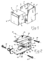
- Figure 1 shows a schematic and perspective view of an electric household appliance such as an oven or a dishwasher, together with the respective compartment of a furniture unit inside which it must be inserted and housed;
- Figure 2 shows a schematic and perspective view, on a larger scale, of a pair of parts for fixing the electric household appliance inside the associated compartment, in their embodiment shown in Figure 1;
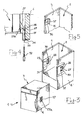
- Figure 3 shows a schematic and perspective view of an electric household appliance, such an oven or a dishwasher, together with the associated compartment of a furniture unit inside which it must be inserted and housed, using the fixing parts designed in accordance with a second embodiment;
- Figure 4 shows a cross-section through a zone for fixing the electric household appliance to the compartment of the furniture unit, after fixing has been performed using the parts designed in accordance with the embodiment of Figure 3, together with a tool able to achieve disengagement of the fixing system;
- Figure 5 shows a schematic and perspective view of a further embodiment of one of the parts for fixing the electric household appliance to the wall of the furniture unit compartment.
- With reference to the abovementioned figures and in particular to Figures 1 and 2, 1 denotes overall an electric household appliance, such as, for example, an oven or a dishwasher, to be mounted fitted inside a
compartment 2 of a kitchen furniture unit, not shown in its entirety in that it is conventional. - The electric household appliance 1 is of the type provided with opposite parallel
vertical walls corresponding walls 5 and 6 of thecompartment 2. - In accordance with the present invention, each of the
walls walls screw 10 which may also be of the self-tapping type. - Still in accordance with the present invention, a second fixing part, denoted overall by 11, is mounted on each of the
walls 5 and 6 of thecompartment 2. In the embodiment according to Figures 1 and 2, thepart 11 comprises a C-shaped support 12 with atransverse core 13 andflanges 14. A pair ofresilient arms transverse core 13 in the opposite direction to the latter. These arms define a gripping member with anopening 17 through which the rigid pin 8 passes during insertion of the electric household appliance and a rear-lyingzone 18 for stably housing the pin once the appliance is correctly and completely snap-engaged inside thecompartment 2. - Consequently, when positioning the fixing part 7 on the
side walls second fixing part 11 on thewalls 5 and 6 of thecompartment 2, it is necessary to take into account the overall depthwise dimensions of the electric household appliance 1 and the position which it must assume inside thecompartment 2. - With reference to Figure 2, it can be seen that the free ends of the
arms portion 19 which is splayed with respect to the direction of insertion of the pin 8, said splayed portion forming a receiving section for insertion of the pin and defining apassage 20 with a narrow cross-section. - Once the pin 8 has reached the
zone 18, its removal in the opposite direction which would allow extraction of the electric household appliance 1 out of thecompartment 2 is prevented, unless an extraction force such as to cause splaying of thearms - Mounting of the
fixing part 11 on thewalls 5 and 6 of thecompartment 2 may be performed by means ofscrews walls 5 and 6, passing throughrespective holes lugs flanges 14 of the support 12. - With reference to Figure 3, it can be seen that the fixing device according to the invention, in a different embodiment thereof, comprises a first part consisting of a resiliently
flexible plate 27 projecting from thewalls stop 28 fixed to each of thewalls 5 and 6 of thecompartment 2. The resilientlyflexible plate 27, while it allows snap-engagement of the electric household appliance 1 inside thecompartment 2, after passing over thestop 28 at the end of the insertion, with its end portion 27a, ensures the stable positioning thereof engaging with the latter, as can be seen from the cross-section shown in Figure 4. - The
plate 27 preferably is in the form of a cam structure with a contrasting action on the side of the end portion 27a. - As an alternative to a structure mounted on the outside of the walls of the electric household appliance, the
plate 27 with its end portion 27a may be replaced by a corresponding shaped part formed by means of drawing of a portion of the corresponding wall of the electric household appliance, making sure that no undesirable openings are formed in the said wall. - The
stop 28, in the embodiment shown in Figure 3, consists of the free edge of aflange 29 folded towards the inside of thecompartment 2 and formed, in a conventional manner, by means of incision of awindow 30 in aplate 31 which is fixed to the associated wall by means of removable fixing means, for example screws. - Once inserted inside the
compartment 2, the electric household appliance 1 may be removed and extracted from the compartment by means of insertion of a tool, for example ascrewdriver 32 shown in Figure 4, through ahole 33 provided in the surroundingpart 34 of the electric household appliance 1, which is envisaged conventionally to make contact against thewalls 5 and 6 of thecompartment 2. - Since the
hole 33 is in alignment with the resilientlyflexible plate 27, using the tip of thetool 32 it is possible to bend either theplate 27 or theflange 29 and cause relative disengagement of the end portion 27a and thestop 28, which allows extraction of the electric household appliance 1 without having to perform the removal of screws. - With reference to Figure 5 it can be seen that the
flange 29 of the embodiment according to Figure 3 is replaced by theflange 35 which is the folded terminal part of aplate 36. - The locating stop in this embodiment therefore consists of the
free edge 37 of theflange 35. - From that described above it is clear that, by means of the fixing device according to the invention, a built-in electric household appliance may be inserted inside the associated compartment of a kitchen furniture unit, with the possibility of performing extraction thereof, even several times, without the risk of damaging the fixing parts which always remain in position mounted on the respective walls.
- The dimensions as well as the materials may be of any nature according to requirements without thereby departing from the scope of the invention as described above and claimed below.
Claims (9)
- Device for fixing an electric household appliance (1) of the type in which at least two walls (3, 4) which are parallel to each other define a transverse dimension of the appliance, inside an associated compartment (2) of a furniture unit defined by at least two opposite walls (5, 6) parallel to each other and separated by a distance substantially equal to or greater than the transverse dimension of the electric household appliance (1) to be mounted inside, characterized in that it comprises:- a first part (7) fixed to each of the walls (3, 4) of the electric household appliance (1) and projecting from the latter towards the outside of the said appliance;- a second part (11) fixed to each of the walls (5, 6) of the compartment (2) of the furniture unit which are situated opposite those of the electric household appliance on which the said first part is mounted, when inserted inside the compartment, said second part (11) being directed towards the inside of the compartment (2);- said first and second parts (7, 11) snap-engaging together resiliently in the direction of insertion of the electric household appliance (1) inside the compartment (2);- said first and second parts (7, 11) being fixed onto the respective walls of the electric household appliance (1) and the compartment (2) of the furniture unit in positions such as to be stably engaged together when the electric household appliance (1) is completely and correctly inserted inside the compartment (2).
- Device according to Claim 1, characterized in that said first part (7) and said second part (11) are provided on respective facing walls which define, respectively, the transverse dimension of the electric household appliance (1) and the compartment of the furniture unit (2).
- Device according to Claims 1 and 2, characterized in that the walls on which the said first and second parts are respectively fixed are vertical walls (3, 4) of the electric household appliance (1) and walls (5, 6) of the compartment (2) of the furniture unit, respectively.
- Device according to Claims 1 to 3, characterized in that said first part (7) consists of a rigid pin (8) projecting from the wall on which it is fixed and said second part (11) consists of a resilient gripping member (15, 16), said pin (8) being stably engaged with said gripping member when the electric household appliance (1) is completely inserted inside the said compartment (2).
- Device according to Claim 4, characterized in that said gripping member comprises a support base (12) for fixing to the associated wall (5, 6) and a pair of resilient arms (15, 16) supported by the said base (12), said resilient arms defining an opening (17) through which the said rigid pin (8) passes during insertion of the electric household appliance (1) and a zone (18) for stably housing the pin (8).
- Device according to Claim 5, characterized in that the resilient arms (15, 16) of the said gripping member, at their free ends (19), have a portion splayed with respect to the direction of insertion of the said pin (8), said splayed portion forming a receiving section for insertion of the pin (8).
- Device according to Claims 1 to 3, characterized in that said first part consists of a resiliently flexible plate (27) projecting from the wall (3, 4) to which it is fixed, while said second part consists of a locating stop (28, 37) fixed to the wall (5, 6) of the compartment (2), said resiliently flexible plate (27) engaging with said stop (28, 37) after passing over it at the end of insertion of the electric household appliance (1) inside the compartment (2), resulting in stable positioning thereof.
- Device according to Claim 7, characterized in that said locating stop (28, 37) comprises a plate (31, 36) fixed to the associated wall (5, 6) by means of removable fixing means.
- Device according to Claims 1 to 3, characterized in that said first part consists of a cam-shaped part formed by means of drawing of the wall of the electric household appliance and projecting from the said wall (3, 4).
Priority Applications (3)
| Application Number | Priority Date | Filing Date | Title |
|---|---|---|---|
| ES06425521T ES2308711T3 (en) | 2006-07-24 | 2006-07-24 | DEVICE FOR FIXING AN EMPOTED APPLIANCE APPLIANCE WITHIN A COMPARTMENT ASSOCIATED WITH A FURNITURE UNIT. |
| EP06425521A EP1882437B1 (en) | 2006-07-24 | 2006-07-24 | Device for fixing a built-in electric household appliance inside the associated compartment of a furniture unit |
| DE602006002389T DE602006002389D1 (en) | 2006-07-24 | 2006-07-24 | Fastening device for installing a household appliance in a kitchen cabinet cell |
Applications Claiming Priority (1)
| Application Number | Priority Date | Filing Date | Title |
|---|---|---|---|
| EP06425521A EP1882437B1 (en) | 2006-07-24 | 2006-07-24 | Device for fixing a built-in electric household appliance inside the associated compartment of a furniture unit |
Publications (2)
| Publication Number | Publication Date |
|---|---|
| EP1882437A1 true EP1882437A1 (en) | 2008-01-30 |
| EP1882437B1 EP1882437B1 (en) | 2008-08-20 |
Family
ID=37554891
Family Applications (1)
| Application Number | Title | Priority Date | Filing Date |
|---|---|---|---|
| EP06425521A Not-in-force EP1882437B1 (en) | 2006-07-24 | 2006-07-24 | Device for fixing a built-in electric household appliance inside the associated compartment of a furniture unit |
Country Status (3)
| Country | Link |
|---|---|
| EP (1) | EP1882437B1 (en) |
| DE (1) | DE602006002389D1 (en) |
| ES (1) | ES2308711T3 (en) |
Cited By (5)
| Publication number | Priority date | Publication date | Assignee | Title |
|---|---|---|---|---|
| WO2009027345A1 (en) * | 2007-08-31 | 2009-03-05 | BSH Bosch und Siemens Hausgeräte GmbH | Stationary household appliance with anti-tip device |
| DE102008020822A1 (en) * | 2008-01-31 | 2009-08-06 | Liebherr-Hausgeräte Ochsenhausen GmbH | Channel for cooling and freezing device, includes arranging channel in such manner cooling and freezing device, which is locked in piece of furniture by channel, where channel is positioned in niche of piece of furniture |
| DE102008042797A1 (en) * | 2008-10-13 | 2010-04-15 | BSH Bosch und Siemens Hausgeräte GmbH | Household appliance for use in arrangement, has housing with cover part, where extending tilting protection element is arranged and raised upward over upper side of cover part |
| EP2979604A1 (en) * | 2014-07-31 | 2016-02-03 | Indesit Company S.p.A. | Integrated dishwasher |
| EP3695748A1 (en) * | 2019-02-14 | 2020-08-19 | Geberit International AG | Installed cabinet assembly |
Families Citing this family (2)
| Publication number | Priority date | Publication date | Assignee | Title |
|---|---|---|---|---|
| ES2396262B1 (en) * | 2009-12-09 | 2013-12-26 | BSH Electrodomésticos España S.A. | DOMESTIC DEVICE WITH A HOUSING, WHICH PRESENTS A SIDE WALL, NEXT TO WHICH IT IS WILLING AT LEAST A DISTANCING ELEMENT |
| IT202200007646A1 (en) * | 2022-04-15 | 2023-10-15 | Elica Spa | Kit for the installation of a first and second built-in appliance |
Citations (4)
| Publication number | Priority date | Publication date | Assignee | Title |
|---|---|---|---|---|
| DE9108044U1 (en) * | 1991-06-29 | 1992-07-23 | Licentia Patent-Verwaltungs-Gmbh, 6000 Frankfurt | Built-in appliance, such as glass ceramic hob or similar |
| DE29621598U1 (en) * | 1996-12-12 | 1997-02-27 | Bosch-Siemens Hausgeräte GmbH, 81669 München | Connection element for attaching a household appliance |
| DE29702118U1 (en) * | 1997-02-07 | 1997-03-27 | Electrolux Siegen GmbH, 57074 Siegen | Fastener |
| GB2313440A (en) * | 1996-05-25 | 1997-11-26 | Stoves Plc | Fitting a cooking appliance |
-
2006
- 2006-07-24 DE DE602006002389T patent/DE602006002389D1/en active Active
- 2006-07-24 EP EP06425521A patent/EP1882437B1/en not_active Not-in-force
- 2006-07-24 ES ES06425521T patent/ES2308711T3/en active Active
Patent Citations (4)
| Publication number | Priority date | Publication date | Assignee | Title |
|---|---|---|---|---|
| DE9108044U1 (en) * | 1991-06-29 | 1992-07-23 | Licentia Patent-Verwaltungs-Gmbh, 6000 Frankfurt | Built-in appliance, such as glass ceramic hob or similar |
| GB2313440A (en) * | 1996-05-25 | 1997-11-26 | Stoves Plc | Fitting a cooking appliance |
| DE29621598U1 (en) * | 1996-12-12 | 1997-02-27 | Bosch-Siemens Hausgeräte GmbH, 81669 München | Connection element for attaching a household appliance |
| DE29702118U1 (en) * | 1997-02-07 | 1997-03-27 | Electrolux Siegen GmbH, 57074 Siegen | Fastener |
Cited By (5)
| Publication number | Priority date | Publication date | Assignee | Title |
|---|---|---|---|---|
| WO2009027345A1 (en) * | 2007-08-31 | 2009-03-05 | BSH Bosch und Siemens Hausgeräte GmbH | Stationary household appliance with anti-tip device |
| DE102008020822A1 (en) * | 2008-01-31 | 2009-08-06 | Liebherr-Hausgeräte Ochsenhausen GmbH | Channel for cooling and freezing device, includes arranging channel in such manner cooling and freezing device, which is locked in piece of furniture by channel, where channel is positioned in niche of piece of furniture |
| DE102008042797A1 (en) * | 2008-10-13 | 2010-04-15 | BSH Bosch und Siemens Hausgeräte GmbH | Household appliance for use in arrangement, has housing with cover part, where extending tilting protection element is arranged and raised upward over upper side of cover part |
| EP2979604A1 (en) * | 2014-07-31 | 2016-02-03 | Indesit Company S.p.A. | Integrated dishwasher |
| EP3695748A1 (en) * | 2019-02-14 | 2020-08-19 | Geberit International AG | Installed cabinet assembly |
Also Published As
| Publication number | Publication date |
|---|---|
| EP1882437B1 (en) | 2008-08-20 |
| DE602006002389D1 (en) | 2008-10-02 |
| ES2308711T3 (en) | 2008-12-01 |
Similar Documents
| Publication | Publication Date | Title |
|---|---|---|
| KR101499098B1 (en) | The door that have a function to prevent from trapping a hand in the door | |
| EP3197252A1 (en) | Slide rail assembly and guiding mechanism thereof | |
| MX2011003484A (en) | Control cabinet arrangement. | |
| EP1882437B1 (en) | Device for fixing a built-in electric household appliance inside the associated compartment of a furniture unit | |
| EP2146615B1 (en) | Under-counter mounting system for a dishwasher, and associated method | |
| JP4936197B2 (en) | Wiring device | |
| US20090252548A1 (en) | Device for Covering a Gap | |
| EP2772693B1 (en) | Encasing for household appliances | |
| CN101171482A (en) | doors for household appliances | |
| EP2204486B1 (en) | Electrical home appliance with top cover | |
| EP1145667B1 (en) | Method for fastening a cupboard door to the door of a built-in refrigerator | |
| CN211484159U (en) | Cooking device and door structure | |
| EP1693937B1 (en) | System for fixing an apparatus-mounting rail to the frame of an electrical control panel | |
| EP2580987B1 (en) | A drawer including a drawer panel and a drawer box | |
| US20220065456A1 (en) | Burner body, metal sheet plate of domestic appliance and fastening system for the burner body on the metal sheet element | |
| EP2722623A1 (en) | System for mounting panels on doors of built-in refrigerators | |
| US8707535B2 (en) | Method for installing a built-in device on a unit niche and adjusting tool | |
| EP3889527A1 (en) | Built-in refrigerator | |
| US20250359666A1 (en) | Built-in system including a built-in cooking appliance and a fixing device for fixing the built-in cooking appliance to a furniture unit | |
| CN223319417U (en) | Drawer assembly for refrigeration equipment and refrigeration equipment | |
| JP6770819B2 (en) | cabinet | |
| KR101186322B1 (en) | Rail preventive device | |
| CN103174706A (en) | Household appliance assembly | |
| WO2015096920A1 (en) | A connection apparatus that provides ease of assembly | |
| US20170003068A1 (en) | Household appliance component having a coextruded decorative part |
Legal Events
| Date | Code | Title | Description |
|---|---|---|---|
| PUAI | Public reference made under article 153(3) epc to a published international application that has entered the european phase |
Free format text: ORIGINAL CODE: 0009012 |
|
| 17P | Request for examination filed |
Effective date: 20070424 |
|
| AK | Designated contracting states |
Kind code of ref document: A1 Designated state(s): AT BE BG CH CY CZ DE DK EE ES FI FR GB GR HU IE IS IT LI LT LU LV MC NL PL PT RO SE SI SK TR |
|
| AX | Request for extension of the european patent |
Extension state: AL BA HR MK YU |
|
| GRAP | Despatch of communication of intention to grant a patent |
Free format text: ORIGINAL CODE: EPIDOSNIGR1 |
|
| GRAS | Grant fee paid |
Free format text: ORIGINAL CODE: EPIDOSNIGR3 |
|
| GRAA | (expected) grant |
Free format text: ORIGINAL CODE: 0009210 |
|
| RTI1 | Title (correction) |
Free format text: DEVICE FOR FIXING A BUILT-IN ELECTRIC HOUSEHOLD APPLIANCE INSIDE THE ASSOCIATED COMPARTMENT OF A FURNITURE UNIT |
|
| AK | Designated contracting states |
Kind code of ref document: B1 Designated state(s): DE ES FR GB IT |
|
| REG | Reference to a national code |
Ref country code: GB Ref legal event code: FG4D |
|
| REF | Corresponds to: |
Ref document number: 602006002389 Country of ref document: DE Date of ref document: 20081002 Kind code of ref document: P |
|
| AKX | Designation fees paid |
Designated state(s): DE ES FR GB IT |
|
| REG | Reference to a national code |
Ref country code: ES Ref legal event code: FG2A Ref document number: 2308711 Country of ref document: ES Kind code of ref document: T3 |
|
| PLBE | No opposition filed within time limit |
Free format text: ORIGINAL CODE: 0009261 |
|
| STAA | Information on the status of an ep patent application or granted ep patent |
Free format text: STATUS: NO OPPOSITION FILED WITHIN TIME LIMIT |
|
| 26N | No opposition filed |
Effective date: 20090525 |
|
| PGFP | Annual fee paid to national office [announced via postgrant information from national office to epo] |
Ref country code: GB Payment date: 20120719 Year of fee payment: 7 |
|
| PGFP | Annual fee paid to national office [announced via postgrant information from national office to epo] |
Ref country code: ES Payment date: 20120704 Year of fee payment: 7 Ref country code: IT Payment date: 20120716 Year of fee payment: 7 Ref country code: FR Payment date: 20120816 Year of fee payment: 7 |
|
| PGFP | Annual fee paid to national office [announced via postgrant information from national office to epo] |
Ref country code: DE Payment date: 20121001 Year of fee payment: 7 |
|
| GBPC | Gb: european patent ceased through non-payment of renewal fee |
Effective date: 20130724 |
|
| REG | Reference to a national code |
Ref country code: DE Ref legal event code: R119 Ref document number: 602006002389 Country of ref document: DE Effective date: 20140201 |
|
| REG | Reference to a national code |
Ref country code: FR Ref legal event code: ST Effective date: 20140331 |
|
| PG25 | Lapsed in a contracting state [announced via postgrant information from national office to epo] |
Ref country code: GB Free format text: LAPSE BECAUSE OF NON-PAYMENT OF DUE FEES Effective date: 20130724 Ref country code: DE Free format text: LAPSE BECAUSE OF NON-PAYMENT OF DUE FEES Effective date: 20140201 |
|
| PG25 | Lapsed in a contracting state [announced via postgrant information from national office to epo] |
Ref country code: FR Free format text: LAPSE BECAUSE OF NON-PAYMENT OF DUE FEES Effective date: 20130731 Ref country code: IT Free format text: LAPSE BECAUSE OF NON-PAYMENT OF DUE FEES Effective date: 20130724 |
|
| PG25 | Lapsed in a contracting state [announced via postgrant information from national office to epo] |
Ref country code: ES Free format text: LAPSE BECAUSE OF NON-PAYMENT OF DUE FEES Effective date: 20130725 |