EP1881649A2 - Display and command console for building technology management - Google Patents
Display and command console for building technology management Download PDFInfo
- Publication number
- EP1881649A2 EP1881649A2 EP07012025A EP07012025A EP1881649A2 EP 1881649 A2 EP1881649 A2 EP 1881649A2 EP 07012025 A EP07012025 A EP 07012025A EP 07012025 A EP07012025 A EP 07012025A EP 1881649 A2 EP1881649 A2 EP 1881649A2
- Authority
- EP
- European Patent Office
- Prior art keywords
- display
- photo
- room
- control unit
- house
- Prior art date
- Legal status (The legal status is an assumption and is not a legal conclusion. Google has not performed a legal analysis and makes no representation as to the accuracy of the status listed.)
- Granted
Links
Images
Classifications
-
- H—ELECTRICITY
- H04—ELECTRIC COMMUNICATION TECHNIQUE
- H04L—TRANSMISSION OF DIGITAL INFORMATION, e.g. TELEGRAPHIC COMMUNICATION
- H04L12/00—Data switching networks
- H04L12/28—Data switching networks characterised by path configuration, e.g. LAN [Local Area Networks] or WAN [Wide Area Networks]
-
- H—ELECTRICITY
- H04—ELECTRIC COMMUNICATION TECHNIQUE
- H04L—TRANSMISSION OF DIGITAL INFORMATION, e.g. TELEGRAPHIC COMMUNICATION
- H04L12/00—Data switching networks
- H04L12/28—Data switching networks characterised by path configuration, e.g. LAN [Local Area Networks] or WAN [Wide Area Networks]
- H04L12/2803—Home automation networks
-
- H—ELECTRICITY
- H04—ELECTRIC COMMUNICATION TECHNIQUE
- H04L—TRANSMISSION OF DIGITAL INFORMATION, e.g. TELEGRAPHIC COMMUNICATION
- H04L12/00—Data switching networks
- H04L12/02—Details
- H04L12/16—Arrangements for providing special services to substations
-
- H—ELECTRICITY
- H04—ELECTRIC COMMUNICATION TECHNIQUE
- H04L—TRANSMISSION OF DIGITAL INFORMATION, e.g. TELEGRAPHIC COMMUNICATION
- H04L12/00—Data switching networks
- H04L12/28—Data switching networks characterised by path configuration, e.g. LAN [Local Area Networks] or WAN [Wide Area Networks]
- H04L12/2803—Home automation networks
- H04L12/2816—Controlling appliance services of a home automation network by calling their functionalities
- H04L12/282—Controlling appliance services of a home automation network by calling their functionalities based on user interaction within the home
Definitions
- the invention relates to a display and control unit of building system technology, which is connected via a processing device and a bus system with actuators, each actuator is assigned a specific address within the bus system and at least one electrical device is connected to each actuator, and which Has touchscreen element for controlling the electrical equipment.
- the invention can be used, for example, for input devices in the field of installation systems of building system technology.
- the commissioning software is bound to symbols or menu texts, whereby the selection of the desired electrical devices by reading and identifying terms or symbols must be realized. For example, on the page “Living room” Terms such as “wall light”, “ceiling light”, “Venetian blind window left”, “Venetian blind window right”, “Venetian blind balcony door” available. By clicking / tapping on one of these terms, the query for the function appears, for example “ON”, “OFF”, “UP” or “DOWN”.
- an input / output device of the building system technology with a freely programmable message and control panel which has a front panel with integrated touchscreen element.
- the touch screen element has graphically designed buttons for programming / operation, which can be executed because of a usable for operation stylus with relatively fine structure. Alternatively, an operation can be done by finger pressure.
- An example of the programming is the setting of various daily timers and / or weekly timers for various devices - such as lighting, shutters, blinds, heating, which are controlled via an installation bus.
- the front panel has a slot for insertion of a memory card in a memory card reader arranged in the interior of the housing for reading / labeling a common memory card (data and / or programs).
- the housing has various recording options (slots) for modules (Ethernet, video, radio).
- the invention has for its object to provide a very easy-to-use commissioning, display and control unit of building system technology.
- the processing device 7 is connected via the bus system 8 with a plurality of actuators 9 or 10 or 11 or 12, to each of which an electrical device 13 or 14 or 15 or 16 is connected.
- a second step for each room of the house and for each electrical device, the assignment between a photo-imaging area of a specific electrical device in the touch screen element and the electrical device itself is done separately.
- the photo of the selected room is on the touch screen element 2 displayed.
- the recognizable in the photo electrical equipment such as a powered by an actuator ceiling or a floor lamp is surrounded by using a pen with a box and assigned to the appropriate actuator of the device by means of his individual address in the system.
- the programming button is to be pressed in a known manner.
- a window with a shutter to be opened / closed by means of a shutter drive is also referred to as an "electrical device".
- the processing device 7 successively takes place the assignment of the address of a particular Actuator to the photo-imaging surface of a particular, shown in a photo in the touch screen element 2 electrical device.
- a symbolic slider is displayed next to the device tapped / clicked for the time of operation, via which the desired brightness or blind position can then be entered directly.
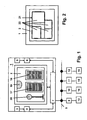
- the floor plan of the house is shown on an overview page on the touchscreen element 2 - see FIG. 2.
- the pen or finger is used to tap the photo-image area of this room in plan 21 - see the different rooms 22 of the floor plan.
- the photograph of this particular room is displayed on the touch screen element 2 and the operation of electrical devices is carried out as explained above.
- the individual rooms of the house are shown in small photos next to each other on the touch screen element 2, whereby the selection of the desired space is simplified.
- the photo of this room is displayed in an enlarged manner.
- a relatively large-scale touchscreen element is advantageous in order to be able to show all rooms with sufficient size and clarity, despite the reduced size of the image.
Abstract
Description
Die Erfindung bezieht sich auf ein Anzeige- und Bediengerät der Gebäudesystemtechnik, welches über eine Verarbeitungseinrichtung und ein Bussystem mit Aktoren verbunden ist, wobei jedem Aktor eine bestimmte Adresse innerhalb des Bussystems zugeordnet ist und an jeden Aktor mindestens ein elektrisches Gerät angeschlossen ist, und welches ein Touchscreen-Element für die Ansteuerung der elektrischen Geräte aufweist. Die Erfindung kann beispielsweise für Eingabegeräte im Bereich Installationssysteme der Gebäudesystemtechnik verwendet werden.The invention relates to a display and control unit of building system technology, which is connected via a processing device and a bus system with actuators, each actuator is assigned a specific address within the bus system and at least one electrical device is connected to each actuator, and which Has touchscreen element for controlling the electrical equipment. The invention can be used, for example, for input devices in the field of installation systems of building system technology.
Im Bereich der Gebäudesystemtechnik sind Eingabegeräte bekannt, die über eine Touchscreen-Oberfläche die Bedienung von an ein Bussystem über Aktoren angeschlossenen elektrischen Geräten (Verbrauchern) erlauben. Üblich ist hier die Darstellung in Menü-Struktur oder durch Symbole, auf die zur Änderung des Schaltzustandes getippt wird. Zur Realisierung von Dimm-Funktionen sind symbolische Schieberegler üblich. Die Inbetriebnahme, d. h. Zuweisung der Aktoren zu den elektrischen Geräten erfolgt über eine separate Inbetriebnahme-Software, mit der die Menüpunkte oder die Symbole den entsprechenden Adressen der Aktoren zugeordnet werden.In the field of building system technology, input devices are known which permit the operation of electrical devices (consumers) connected to a bus system via actuators via a touchscreen interface. Common here is the representation in menu structure or by symbols, which is tapped to change the switching state. To implement dimming functions, symbolic sliders are common. Commissioning, d. H. Assignment of the actuators to the electrical devices takes place via a separate commissioning software, with which the menu items or the symbols are assigned to the corresponding addresses of the actuators.
Die Inbetriebnahme-Software ist an Symbole oder Menü-Texte gebunden, wodurch die Auswahl der gewünschten elektrischen Geräte durch Lesen und Identifizieren von Begriffen oder Symbolen realisiert werden muss. Beispielsweise sind auf der Seite "Wohnzimmer" Begriffe wie "Wandleuchte", "Deckenleuchte", "Jalousie Fenster links", "Jalousie Fenster rechts", "Jalousie Balkontür" vorhanden. Durch Klicken / Tippen auf einen dieser Begriffe erscheint die Abfrage zur Funktion, beispielsweise "EIN", "AUS", "AUF" oder "AB".The commissioning software is bound to symbols or menu texts, whereby the selection of the desired electrical devices by reading and identifying terms or symbols must be realized. For example, on the page "Living room" Terms such as "wall light", "ceiling light", "Venetian blind window left", "Venetian blind window right", "Venetian blind balcony door" available. By clicking / tapping on one of these terms, the query for the function appears, for example "ON", "OFF", "UP" or "DOWN".
Aus der
Der Erfindung liegt die Aufgabe zugrunde, ein sehr einfach bedienbares Inbetriebnahme-, Anzeige- und Bediengerät der Gebäudesystemtechnik anzugeben.The invention has for its object to provide a very easy-to-use commissioning, display and control unit of building system technology.
Diese Aufgabe wird in Verbindung mit den Merkmalen des Oberbegriffes erfindungsgemäß dadurch gelöst,
- dass auf dem Touchscreen-Element mindestens ein Raum eines Hauses oder ein Teilbereich eines Raumes in Form eines Fotos abgebildet ist, auf welchem die anzusteuernden elektrischen Geräte dieses Raumes erkennbar sind,
- dass über die Verarbeitungseinrichtung die Foto-Abbildungsfläche eines bestimmten elektrischen Gerätes einer dem Aktor dieses elektrischen Gerätes zugeordneten Adresse zugewiesen ist,
- dass bei Berührung der Foto-Abbildungsfläche über die Verarbeitungseinrichtung eine gewünschte Aktor-Funktion umgesetzt wird.
- at least one room of a house or a partial area of a room in the form of a photo is shown on the touchscreen element, on which the electrical appliances of this room to be controlled are recognizable,
- the photo-imaging surface of a specific electrical device is assigned to an address assigned to the actuator of this electrical device via the processing device,
- when the photoimaging surface is touched by the processing device, a desired actuator function is implemented.
Die mit der Erfindung erzielbaren Vorteile bestehen insbesondere darin, dass nicht erst Menütexte und Begriffe gelesen oder Symbole identifiziert und verstanden werden müssen, bevor ein bestimmtes elektrisches Gerät in gewünschter Weise und unter Verwendung des Anzeige- und Bediengerätes angesteuert werden kann. Das anzusteuernde Gerät wird vielmehr unmittelbar auf dem Foto erkannt und mittels Berührung der Foto-Abbildungsfläche dieses Gerätes unmittelbar angesteuert.The achievable with the present invention consist in particular that not only menu texts and terms read or symbols must be identified and understood before a particular electrical device can be controlled in the desired manner and using the display and control unit. The device to be controlled is rather recognized directly on the photo and directly controlled by touching the photo-imaging surface of this device.
Weitere Vorteile sind aus der nachstehenden Beschreibung ersichtlich.Further advantages will be apparent from the following description.
Vorteilhafte Ausgestaltungen der Erfindung sind in den Unteransprüchen gekennzeichnet.Advantageous embodiments of the invention are characterized in the subclaims.
Die Erfindung wird nachstehend anhand der in der Zeichnung dargestellten Ausführungsbeispiele erläutert. Es zeigen:
- Fig.1
- eine schematische Darstellung eines Anzeige- und Bediengeräts der Gebäudesystemtechnik mit mehreren an ein Bussystem angeschlossenen elektrischen Geräten,
- Fig. 2
- ein Anzeige- und Bediengerät mit Darstellung des Grundrisses eines Hauses.
- Fig.1
- a schematic representation of a display and control unit of building system technology with multiple electrical devices connected to a bus system,
- Fig. 2
- a display and control unit with representation of the floor plan of a house.
In Fig. 1 ist eine schematische Darstellung eines Anzeige- und Bediengeräts der Gebäudesystemtechnik mit mehreren an ein Bussystem angeschlossenen elektrischen Geräten dargestellt. Es ist ein Anzeige- und Bediengerät 1 gezeigt, welches aufweist:
- • ein Touchscreen-
Element 2, - • eine eingebaute Kamera (optional) 3,
- • ein
Speicherelement 4 zur Abspeicherung von Bildinformationen derKamera 3, - • ein
Kartenlesegerät 5 zur Eingabe von Bildinformationen mittels Karte, beispielsweise SD-Karte, - • ein
Speicherelement 6 zur Abspeicherung von über dasKartenlesegerät 5 eingegebenen Bildinformationen, - • eine
Verarbeitungseinrichtung 7, welche mit dem Touchscreen-Element 2, demSpeicherelement 4, demSpeicherelement 6 und dem Bussystem verbunden ist.
- A
touchscreen element 2, - • a built-in camera (optional) 3,
- A
memory element 4 for storing image information of thecamera 3, - A
card reader 5 for inputting image information by means of a card, for example an SD card, - A
memory element 6 for storing image information input via thecard reader 5, - A
processing device 7, which is connected to thetouchscreen element 2, thememory element 4, thememory element 6 and the bus system.
Die Verarbeitungseinrichtung 7 ist über das Bussystem 8 mit mehreren Aktoren 9 bzw. 10 bzw. 11 bzw. 12 verbunden, an welche jeweils ein elektrisches Gerät 13 bzw. 14 bzw. 15 bzw. 16 angeschlossen ist.The
Für die Inbetriebnahme des Anzeige- und Bediengerätes 1 werden in einem ersten Schritt Bildinformationen sowohl des Grundrisses des Hauses - zweckmäßig über eine geeignete Karte und das Kartenlesegerät 5 zum Speicherelement 6 - als auch Fotos betreffend die einzelnen Räume des Hauses eingegeben. Letzteres kann erfolgen
- • durch Eigenaufnahme mittels der
Kamera 3 und Abspeicherung imSpeicherelement 4, - • durch Fremdaufnahme mittels einer separaten Kamera, wobei das Fremdbild auf einem Speichermedium abgespeichert wird und ein Einlesen in das
Speicherelement 6 mittels geeigneter Karte und dasKartenlesegerät 5 erfolgt.
- By self-recording by means of the
camera 3 and storage in thestorage element 4, - • By foreign recording by means of a separate camera, wherein the foreign image is stored on a storage medium and a reading into the
memory element 6 by means of a suitable card and thecard reader 5 takes place.
In einem zweiten Schritt erfolgt für jeden Raum des Hauses und für jedes elektrische Gerät separat die Zuordnung zwischen einer Foto-Abbildungsfläche eines bestimmten elektrischen Gerätes im Tochscreen-Element und dem elektrischen Gerät selbst. Hierzu wird auf dem Touchscreen-Element 2 das Foto des gewählten Raumes angezeigt. Das auf dem Foto erkennbare elektrischen Geräte, beispielsweise eine über einen aktor betriebene Deckenleuchte oder eine Standleuchte, wird unter Verwendung eines Stiftes mit einem Kästchen umrandet und dem entsprechenden Aktor des Gerätes mittels seiner im System individuellen Adresse zugeordnet. Am jeweiligen Aktor selbst ist hierzu in bekannter Art und Weise die Programmiertaste zu drücken. In diesem Zusammenhang wird auch ein Fenster mit einer mittels eines Jalousieantriebs zu öffnenden / zu schließenden Jalousie als "elektrisches Gerät" bezeichnet. Auf diese Weise erfolgt mittels der Verarbeitungseinrichtung 7 sukzessive die Zuordnung der Adresse eines bestimmten Aktors zur Foto-Abbildungsfläche eines bestimmten, in einem Foto im Touchscreen-Element 2 gezeigten elektrischen Geräts.In a second step, for each room of the house and for each electrical device, the assignment between a photo-imaging area of a specific electrical device in the touch screen element and the electrical device itself is done separately. For this purpose, the photo of the selected room is on the
Für die Ansteuerung eines elektrischen Gerätes während des späteren Betriebes reicht es dann aus, das anzusteuernde Gerät auf dem Touchscreen-Element 2 anzuklicken bzw. mit einem Stift auf die Foto-Abbildungsfläche des anzusteuernden Geräts zu tippen, um eine gewünschte Aktor-Funktion einzuleiten. Folgende Aktor-Funktionen sind realisierbar (keine abschließende Darstellung):
- • Für das Einschalten / Ausschalten einer Beleuchtung -
siehe Deckenleuchte 19 in Fig. 1 - genügt es, mit dem Stift oder mit dem Finger auf die Foto-Abbildungsfläche des anzusteuernden Gerät zu tippen, hierauf erfolgt bei einem ausgeschalteten Gerät das Einschalten sowie bei einem eingeschalteten Gerät das Ausschalten. - • Zum Aufwärts-Dimmen einer Beleuchtung (in Richtung "heller") -
siehe Standleuchte 20 in Fig. 1 - wird mit dem Stift oder Finger von unten nach oben über die Foto-Abbildungsfläche des anzusteuernden Geräts gestrichen, bis die gewünschte Helligkeit erreicht ist oder es wird kurz auf die Foto-Abbildungsfläche der Beleuchtung getippt. - • Zum Abwärts-Dimmen einer Beleuchtung (in Richtung "dunkler") wird mit dem Stift oder Finger von oben nach unten über die Foto-Abbildungsfläche des anzusteuernden Geräts gestrichen, bis die gewünschte Helligkeit erreicht ist oder es wird kurz auf die Foto-Abbildungsfläche der Beleuchtung getippt.
- • Zum Öffnen einer Jalousie -
siehe Jalousien - • Zum Schließen einer Jalousie wird mit dem Stift oder-Finger von oben nach unten über die Foto-Abbildungsfläche der anzusteuernden Jalousie bis zur gewünschten Position gestrichen. Ein kurzes Tippen auf die Foto-Abbildungsfläche der Jalousie lässt sie an der augenblicklichen Position anhalten.
- • For the switching on / off of a lighting - see
ceiling light 19 in Fig. 1 - it is sufficient to tap with the stylus or with your finger on the photo-imaging surface of the device to be controlled, this is done with a turned off the power and a switched on Device switching off. - • For upward dimming of a lighting (in direction "brighter") - see
floor lamp 20 in Fig. 1 - is painted with the pen or finger from bottom to top over the photo-imaging surface of the device to be controlled until the desired brightness is reached or it is briefly typed on the photo-imaging surface of the lighting. - • For dimming a light downwards (towards "darker"), use the stylus or the finger to stroke across the photoimaging surface of the device to be controlled, from top to bottom, until the desired brightness is achieved, or it is briefly pressed onto the photoimaging surface of the device Lighting typed.
- • To open a blind - see
Venetian blinds - • To close a Venetian blind, stroke the stylus or the pen from top to bottom across the photoimaging area of the shutter to be controlled to the desired position. A brief tap on the photo-imaging surface of the blind lets it stop at its current position.
In einer abgewandelten Ausführungsform wird beim Antippen / Anklicken einer Leuchte mit Dimm-Aktor oder einer Jalousie ein symbolischer Schieberegler neben dem angetippten / angeklickten Gerät für die Zeit der Bedienung eingeblendet, über den dann die gewünschte Helligkeit oder Jalousieposition direkt eingegeben werden kann.In a modified embodiment, when touching / clicking on a luminaire with dimming actuator or a venetian blind, a symbolic slider is displayed next to the device tapped / clicked for the time of operation, via which the desired brightness or blind position can then be entered directly.
Alle vorstehend angeführten Funktionen erfolgen unter Einsatz der Verarbeitungseinrichtung 7, des Bussystems 8 und der per Adresse angesprochenen Aktoren.All the above-mentioned functions are carried out using the
Können alle über das Bussystem 8 ansteuerbaren elektrischen Geräte eines Raumes nicht in einem einzigen Foto dargestellt werden, werden zweckmäßig zwei oder mehr Fotos dieses Raumes nebeneinander auf dem Touchscreen-Element 2 abgebildet, beispielsweise zeigt jedes Foto eine Wand des Raumes.If all electrical devices of a room that can be controlled via the
Zur Auswahl eines bestimmten Raumes ist auf dem Touchscreen-Element 2 auf einer Übersichtsseite der Grundriss des Hauses dargestellt - siehe Fig. 2. Zur Auswahl des gewünschten Raumes wird mit dem Stift oder Finger auf die Foto-Abbildungsfläche dieses Raumes im Grundriss 21 getippt - siehe die verschiedenen Räume 22 des Grundrisses. Hierauf wird das Foto dieses bestimmten Raumes auf dem Touchscreen-Element 2 abgebildet und die Bedienung von elektrischen Geräten erfolgt wie vorstehend erläutert.To select a specific room, the floor plan of the house is shown on an overview page on the touchscreen element 2 - see FIG. 2. To select the desired room, the pen or finger is used to tap the photo-image area of this room in plan 21 - see the
Alternativ sind auf dem Touchscreen-Element 2 die einzelnen Räume des Hauses in kleinen Fotos nebeneinander dargestellt, wodurch die Auswahl des gewünschten Raumes vereinfacht wird. Durch Tippen auf das Foto des gewünschten Raumes wird das Foto dieses Raumes in vergrößerter Weise abgebildet. Allerdings ist bei dieser Abbildungsform ein relativ großflächiges Touchscreen-Element vorteilhaft, um zunächst trotz der verkleinerten Abbildung alle Räume mit ausreichender Größe und Deutlichkeit zeigen zu können.Alternatively, the individual rooms of the house are shown in small photos next to each other on the
Wenn vorstehend von der Abbildung eines Raumes in Form eines Fotos die Rede ist, umfasst dies auch abstrahierende Grafiken, nicht jedoch die Abbildung von Geräten durch Symbole.When referring to the illustration of a space in the form of a photo above, this also includes abstracting graphics, but not the illustration of devices by symbols.
- 11
- Anzeige- und BediengerätDisplay and operating device
- 22
- Touchscreen-ElementTouchscreen element
- 33
- Kameracamera
- 44
- Speicherelementstorage element
- 55
- KartenlesegerätCard Reader
- 66
- Speicherelementstorage element
- 77
- Verarbeitungseinrichtungprocessing device
- 88th
- Bussystembus system
- 99
- Aktoractuator
- 1010
- Aktoractuator
- 1111
- Aktoractuator
- 1212
- Aktoractuator
- 1313
- elektrisches Gerätelectric device
- 1414
- elektrisches Gerätelectric device
- 1515
- elektrisches Gerätelectric device
- 1616
- elektrisches Gerätelectric device
- 1717
- Jalousielouvre
- 1818
- Jalousielouvre
- 1919
- Deckenleuchteceiling light
- 2020
- Standleuchtefloor lamp
- 2121
- Grundriss eines HausesFloor plan of a house
- 2222
- Räume des HausesRooms of the house
Claims (9)
Applications Claiming Priority (1)
| Application Number | Priority Date | Filing Date | Title |
|---|---|---|---|
| DE102006033134A DE102006033134A1 (en) | 2006-07-18 | 2006-07-18 | Display and operating device of building system technology |
Publications (3)
| Publication Number | Publication Date |
|---|---|
| EP1881649A2 true EP1881649A2 (en) | 2008-01-23 |
| EP1881649A3 EP1881649A3 (en) | 2012-07-11 |
| EP1881649B1 EP1881649B1 (en) | 2019-02-27 |
Family
ID=38645851
Family Applications (1)
| Application Number | Title | Priority Date | Filing Date |
|---|---|---|---|
| EP07012025.8A Active EP1881649B1 (en) | 2006-07-18 | 2007-06-20 | Display and command console for building technology management |
Country Status (6)
| Country | Link |
|---|---|
| EP (1) | EP1881649B1 (en) |
| KR (1) | KR20080008236A (en) |
| CN (1) | CN101118438B (en) |
| DE (1) | DE102006033134A1 (en) |
| RU (1) | RU2007127419A (en) |
| SG (2) | SG139676A1 (en) |
Cited By (14)
| Publication number | Priority date | Publication date | Assignee | Title |
|---|---|---|---|---|
| DE102009038204A1 (en) | 2009-08-20 | 2011-04-21 | Siemens Aktiengesellschaft | Solar-powered actuator e.g. electrical actuator, for driving e.g. window blind, of industrial building installation, has wire whose end is coupled to installation, so that installation or installation part is moved during elongation of wire |
| EP2523396A2 (en) | 2011-05-12 | 2012-11-14 | Abb Ag | Portable display and operation device |
| EP2105711A3 (en) * | 2008-03-28 | 2013-10-23 | Abb Ag | Assembly for generating energy and display in building system technology |
| DE102012010044A1 (en) | 2012-05-23 | 2013-11-28 | Volkswagen Aktiengesellschaft | Device for controlling a lighting in a vehicle interior |
| EP2717140A1 (en) * | 2011-05-24 | 2014-04-09 | Mitsubishi Electric Corporation | Equipment control device, operation reception method, and program |
| EP3373453A2 (en) | 2017-03-08 | 2018-09-12 | Loxone Electronics GmbH | Touch sensitive operating element |
| US10353576B2 (en) * | 2016-06-12 | 2019-07-16 | Apple Inc. | User interface for managing controllable external devices |
| EP3572888A1 (en) * | 2014-02-26 | 2019-11-27 | Zen Ecosystems IP Pty Ltd | User interface for a consumer product system |
| WO2020144081A1 (en) * | 2019-01-11 | 2020-07-16 | Shpi Gmbh | Universal multifunctional device |
| US10779085B1 (en) | 2019-05-31 | 2020-09-15 | Apple Inc. | User interfaces for managing controllable external devices |
| US10820058B2 (en) | 2018-05-07 | 2020-10-27 | Apple Inc. | User interfaces for viewing live video feeds and recorded video |
| US10969925B1 (en) | 2015-06-26 | 2021-04-06 | Amdocs Development Limited | System, method, and computer program for generating a three-dimensional navigable interactive model of a home |
| US11079913B1 (en) | 2020-05-11 | 2021-08-03 | Apple Inc. | User interface for status indicators |
| US11363071B2 (en) | 2019-05-31 | 2022-06-14 | Apple Inc. | User interfaces for managing a local network |
Families Citing this family (1)
| Publication number | Priority date | Publication date | Assignee | Title |
|---|---|---|---|---|
| DE102011054357B4 (en) * | 2011-10-10 | 2014-06-12 | Gira Giersiepen Gmbh & Co. Kg | Control unit in an electrical installation system and electrical installation system comprising at least one power unit and at least one control panel |
Citations (2)
| Publication number | Priority date | Publication date | Assignee | Title |
|---|---|---|---|---|
| US6756998B1 (en) | 2000-10-19 | 2004-06-29 | Destiny Networks, Inc. | User interface and method for home automation system |
| DE102004016604A1 (en) | 2004-04-03 | 2005-10-27 | Abb Patent Gmbh | Input / output device of building system technology |
Family Cites Families (9)
| Publication number | Priority date | Publication date | Assignee | Title |
|---|---|---|---|---|
| US5410326A (en) * | 1992-12-04 | 1995-04-25 | Goldstein; Steven W. | Programmable remote control device for interacting with a plurality of remotely controlled devices |
| EP1015962B2 (en) * | 1997-06-25 | 2006-11-02 | Samsung Electronics Co., Ltd. | Method for creating home network macros |
| GB9924177D0 (en) * | 1999-10-12 | 1999-12-15 | Srs Technology Limited | Communication and control system |
| US7574323B2 (en) * | 2001-12-17 | 2009-08-11 | Wireless Valley Communications, Inc. | Textual and graphical demarcation of location, and interpretation of measurements |
| US20040083128A1 (en) * | 2002-01-24 | 2004-04-29 | Buckingham Duane W. | Smart router for a guest room service and control system |
| US7047092B2 (en) * | 2003-04-08 | 2006-05-16 | Coraccess Systems | Home automation contextual user interface |
| US20050015222A1 (en) * | 2003-07-14 | 2005-01-20 | Harrington Kevin J. | System and method for automated building incident response |
| US7136709B2 (en) * | 2003-11-04 | 2006-11-14 | Universal Electronics Inc. | Home appliance control system and methods in a networked environment |
| JP2006098256A (en) * | 2004-09-30 | 2006-04-13 | Ricoh Co Ltd | Three-dimensional surface model preparing system, image processing system, program, and information recording medium |
-
2006
- 2006-07-18 DE DE102006033134A patent/DE102006033134A1/en not_active Ceased
-
2007
- 2007-06-20 EP EP07012025.8A patent/EP1881649B1/en active Active
- 2007-07-12 KR KR1020070070063A patent/KR20080008236A/en not_active Application Discontinuation
- 2007-07-17 CN CN2007101368491A patent/CN101118438B/en active Active
- 2007-07-17 RU RU2007127419/09A patent/RU2007127419A/en unknown
- 2007-07-18 SG SG200705311-9A patent/SG139676A1/en unknown
- 2007-07-18 SG SG201105153-9A patent/SG173380A1/en unknown
Patent Citations (2)
| Publication number | Priority date | Publication date | Assignee | Title |
|---|---|---|---|---|
| US6756998B1 (en) | 2000-10-19 | 2004-06-29 | Destiny Networks, Inc. | User interface and method for home automation system |
| DE102004016604A1 (en) | 2004-04-03 | 2005-10-27 | Abb Patent Gmbh | Input / output device of building system technology |
Cited By (24)
| Publication number | Priority date | Publication date | Assignee | Title |
|---|---|---|---|---|
| EP2105711A3 (en) * | 2008-03-28 | 2013-10-23 | Abb Ag | Assembly for generating energy and display in building system technology |
| DE102009038204A1 (en) | 2009-08-20 | 2011-04-21 | Siemens Aktiengesellschaft | Solar-powered actuator e.g. electrical actuator, for driving e.g. window blind, of industrial building installation, has wire whose end is coupled to installation, so that installation or installation part is moved during elongation of wire |
| EP2523396A2 (en) | 2011-05-12 | 2012-11-14 | Abb Ag | Portable display and operation device |
| DE102011101387A1 (en) | 2011-05-12 | 2012-11-15 | Abb Ag | Portable display and control unit |
| EP2717140A1 (en) * | 2011-05-24 | 2014-04-09 | Mitsubishi Electric Corporation | Equipment control device, operation reception method, and program |
| EP2717140A4 (en) * | 2011-05-24 | 2014-12-03 | Mitsubishi Electric Corp | Equipment control device, operation reception method, and program |
| DE102012010044A1 (en) | 2012-05-23 | 2013-11-28 | Volkswagen Aktiengesellschaft | Device for controlling a lighting in a vehicle interior |
| WO2013174580A1 (en) | 2012-05-23 | 2013-11-28 | Volkswagen Aktiengesellschaft | Device for controlling lighting in a vehicle interior |
| EP3572888A1 (en) * | 2014-02-26 | 2019-11-27 | Zen Ecosystems IP Pty Ltd | User interface for a consumer product system |
| US10969925B1 (en) | 2015-06-26 | 2021-04-06 | Amdocs Development Limited | System, method, and computer program for generating a three-dimensional navigable interactive model of a home |
| US10353576B2 (en) * | 2016-06-12 | 2019-07-16 | Apple Inc. | User interface for managing controllable external devices |
| US10635303B2 (en) | 2016-06-12 | 2020-04-28 | Apple Inc. | User interface for managing controllable external devices |
| EP3565121A1 (en) | 2017-03-08 | 2019-11-06 | Loxone Electronics GmbH | Touch sensitive operating element |
| EP3373453A2 (en) | 2017-03-08 | 2018-09-12 | Loxone Electronics GmbH | Touch sensitive operating element |
| US10904628B2 (en) | 2018-05-07 | 2021-01-26 | Apple Inc. | User interfaces for viewing live video feeds and recorded video |
| US10820058B2 (en) | 2018-05-07 | 2020-10-27 | Apple Inc. | User interfaces for viewing live video feeds and recorded video |
| WO2020144081A1 (en) * | 2019-01-11 | 2020-07-16 | Shpi Gmbh | Universal multifunctional device |
| US10904029B2 (en) | 2019-05-31 | 2021-01-26 | Apple Inc. | User interfaces for managing controllable external devices |
| US10779085B1 (en) | 2019-05-31 | 2020-09-15 | Apple Inc. | User interfaces for managing controllable external devices |
| US11363071B2 (en) | 2019-05-31 | 2022-06-14 | Apple Inc. | User interfaces for managing a local network |
| US11785387B2 (en) | 2019-05-31 | 2023-10-10 | Apple Inc. | User interfaces for managing controllable external devices |
| US11824898B2 (en) | 2019-05-31 | 2023-11-21 | Apple Inc. | User interfaces for managing a local network |
| US11079913B1 (en) | 2020-05-11 | 2021-08-03 | Apple Inc. | User interface for status indicators |
| US11513667B2 (en) | 2020-05-11 | 2022-11-29 | Apple Inc. | User interface for audio message |
Also Published As
| Publication number | Publication date |
|---|---|
| RU2007127419A (en) | 2009-01-27 |
| KR20080008236A (en) | 2008-01-23 |
| EP1881649A3 (en) | 2012-07-11 |
| EP1881649B1 (en) | 2019-02-27 |
| CN101118438A (en) | 2008-02-06 |
| SG139676A1 (en) | 2008-02-29 |
| SG173380A1 (en) | 2011-08-29 |
| DE102006033134A1 (en) | 2008-01-24 |
| CN101118438B (en) | 2011-11-16 |
Similar Documents
| Publication | Publication Date | Title |
|---|---|---|
| EP1881649B1 (en) | Display and command console for building technology management | |
| DE102011054357B4 (en) | Control unit in an electrical installation system and electrical installation system comprising at least one power unit and at least one control panel | |
| DE602005002889T2 (en) | A method of operating a shutter controlled and powered from a wire interface | |
| EP1582947B1 (en) | Input/Output device of home automation systems | |
| EP2955599A1 (en) | Method for controlling a home automation network, control device and home automation network | |
| DE102011102038A1 (en) | A home automation control system and method for controlling a home automation control system | |
| EP1266269B1 (en) | System and control device for the control of several actuators in a room | |
| EP3757341A1 (en) | Door drive unit for automatic driving of a door with an user interface unit mounted on the drive unit | |
| EP3416337A1 (en) | Device for automation of a house or building | |
| DE202013104254U1 (en) | Electronic communication device for home control | |
| DE19634165A1 (en) | Circuit arrangement and method for controlling electrical household appliances | |
| DE102012006898A1 (en) | Arrangement for controlling actuator of e.g. ceiling lamp, has input/output unit that performs snapshot operation to automatically acquire operating mode of actuators | |
| EP2523396A2 (en) | Portable display and operation device | |
| DE69734261T2 (en) | Method and device for configuring a communication network | |
| EP0600119B1 (en) | Switch device for technical domestic installation | |
| EP2658180A1 (en) | Built-in electrical installation device construction kit system | |
| EP3657286B1 (en) | Method for configuring an actuator device in a building automation system | |
| DE102006025300B4 (en) | Electrical installation device | |
| DE102014207638A1 (en) | HMI device for the control of lights, blinds and / or air conditioners | |
| EP3627317B1 (en) | Method for configuring a vacuum device | |
| DE102007015914B3 (en) | Bus sharing unit for use in e.g. networked system, has counter for time measurement and volatile and/or non-volatile memory for storing transferred data and automatic execution of function in dependence of data and information of counter | |
| EP3731042A1 (en) | Electric/electronic installation system | |
| DE202010002903U1 (en) | Central control system for the control and operation of building services equipment | |
| DE102007022342A1 (en) | Sensor unit with several operating or functional elements | |
| DE102018129687A1 (en) | Control unit for home automation |
Legal Events
| Date | Code | Title | Description |
|---|---|---|---|
| PUAI | Public reference made under article 153(3) epc to a published international application that has entered the european phase |
Free format text: ORIGINAL CODE: 0009012 |
|
| AK | Designated contracting states |
Kind code of ref document: A2 Designated state(s): AT BE BG CH CY CZ DE DK EE ES FI FR GB GR HU IE IS IT LI LT LU LV MC MT NL PL PT RO SE SI SK TR |
|
| AX | Request for extension of the european patent |
Extension state: AL BA HR MK YU |
|
| PUAL | Search report despatched |
Free format text: ORIGINAL CODE: 0009013 |
|
| AK | Designated contracting states |
Kind code of ref document: A3 Designated state(s): AT BE BG CH CY CZ DE DK EE ES FI FR GB GR HU IE IS IT LI LT LU LV MC MT NL PL PT RO SE SI SK TR |
|
| AX | Request for extension of the european patent |
Extension state: AL BA HR MK RS |
|
| RIC1 | Information provided on ipc code assigned before grant |
Ipc: H04L 12/24 20060101ALI20120607BHEP Ipc: H04L 12/28 20060101AFI20120607BHEP |
|
| 17P | Request for examination filed |
Effective date: 20121130 |
|
| AKX | Designation fees paid |
Designated state(s): AT BE BG CH CY CZ DE DK EE ES FI FR GB GR HU IE IS IT LI LT LU LV MC MT NL PL PT RO SE SI SK TR |
|
| 17Q | First examination report despatched |
Effective date: 20130918 |
|
| RAP1 | Party data changed (applicant data changed or rights of an application transferred) |
Owner name: ABB AG |
|
| STAA | Information on the status of an ep patent application or granted ep patent |
Free format text: STATUS: EXAMINATION IS IN PROGRESS |
|
| GRAP | Despatch of communication of intention to grant a patent |
Free format text: ORIGINAL CODE: EPIDOSNIGR1 |
|
| STAA | Information on the status of an ep patent application or granted ep patent |
Free format text: STATUS: GRANT OF PATENT IS INTENDED |
|
| INTG | Intention to grant announced |
Effective date: 20180924 |
|
| GRAS | Grant fee paid |
Free format text: ORIGINAL CODE: EPIDOSNIGR3 |
|
| GRAA | (expected) grant |
Free format text: ORIGINAL CODE: 0009210 |
|
| STAA | Information on the status of an ep patent application or granted ep patent |
Free format text: STATUS: THE PATENT HAS BEEN GRANTED |
|
| AK | Designated contracting states |
Kind code of ref document: B1 Designated state(s): AT BE BG CH CY CZ DE DK EE ES FI FR GB GR HU IE IS IT LI LT LU LV MC MT NL PL PT RO SE SI SK TR |
|
| REG | Reference to a national code |
Ref country code: GB Ref legal event code: FG4D Free format text: NOT ENGLISH |
|
| REG | Reference to a national code |
Ref country code: CH Ref legal event code: EP |
|
| REG | Reference to a national code |
Ref country code: AT Ref legal event code: REF Ref document number: 1102953 Country of ref document: AT Kind code of ref document: T Effective date: 20190315 |
|
| REG | Reference to a national code |
Ref country code: IE Ref legal event code: FG4D Free format text: LANGUAGE OF EP DOCUMENT: GERMAN |
|
| REG | Reference to a national code |
Ref country code: DE Ref legal event code: R096 Ref document number: 502007016596 Country of ref document: DE |
|
| REG | Reference to a national code |
Ref country code: NL Ref legal event code: FP |
|
| REG | Reference to a national code |
Ref country code: LT Ref legal event code: MG4D |
|
| PG25 | Lapsed in a contracting state [announced via postgrant information from national office to epo] |
Ref country code: LT Free format text: LAPSE BECAUSE OF FAILURE TO SUBMIT A TRANSLATION OF THE DESCRIPTION OR TO PAY THE FEE WITHIN THE PRESCRIBED TIME-LIMIT Effective date: 20190227 Ref country code: PT Free format text: LAPSE BECAUSE OF FAILURE TO SUBMIT A TRANSLATION OF THE DESCRIPTION OR TO PAY THE FEE WITHIN THE PRESCRIBED TIME-LIMIT Effective date: 20190627 Ref country code: FI Free format text: LAPSE BECAUSE OF FAILURE TO SUBMIT A TRANSLATION OF THE DESCRIPTION OR TO PAY THE FEE WITHIN THE PRESCRIBED TIME-LIMIT Effective date: 20190227 Ref country code: SE Free format text: LAPSE BECAUSE OF FAILURE TO SUBMIT A TRANSLATION OF THE DESCRIPTION OR TO PAY THE FEE WITHIN THE PRESCRIBED TIME-LIMIT Effective date: 20190227 |
|
| PG25 | Lapsed in a contracting state [announced via postgrant information from national office to epo] |
Ref country code: BG Free format text: LAPSE BECAUSE OF FAILURE TO SUBMIT A TRANSLATION OF THE DESCRIPTION OR TO PAY THE FEE WITHIN THE PRESCRIBED TIME-LIMIT Effective date: 20190527 Ref country code: LV Free format text: LAPSE BECAUSE OF FAILURE TO SUBMIT A TRANSLATION OF THE DESCRIPTION OR TO PAY THE FEE WITHIN THE PRESCRIBED TIME-LIMIT Effective date: 20190227 Ref country code: GR Free format text: LAPSE BECAUSE OF FAILURE TO SUBMIT A TRANSLATION OF THE DESCRIPTION OR TO PAY THE FEE WITHIN THE PRESCRIBED TIME-LIMIT Effective date: 20190528 Ref country code: IS Free format text: LAPSE BECAUSE OF FAILURE TO SUBMIT A TRANSLATION OF THE DESCRIPTION OR TO PAY THE FEE WITHIN THE PRESCRIBED TIME-LIMIT Effective date: 20190627 |
|
| RAP2 | Party data changed (patent owner data changed or rights of a patent transferred) |
Owner name: ABB SCHWEIZ AG |
|
| PGFP | Annual fee paid to national office [announced via postgrant information from national office to epo] |
Ref country code: CH Payment date: 20190619 Year of fee payment: 13 |
|
| PG25 | Lapsed in a contracting state [announced via postgrant information from national office to epo] |
Ref country code: ES Free format text: LAPSE BECAUSE OF FAILURE TO SUBMIT A TRANSLATION OF THE DESCRIPTION OR TO PAY THE FEE WITHIN THE PRESCRIBED TIME-LIMIT Effective date: 20190227 Ref country code: CZ Free format text: LAPSE BECAUSE OF FAILURE TO SUBMIT A TRANSLATION OF THE DESCRIPTION OR TO PAY THE FEE WITHIN THE PRESCRIBED TIME-LIMIT Effective date: 20190227 Ref country code: SK Free format text: LAPSE BECAUSE OF FAILURE TO SUBMIT A TRANSLATION OF THE DESCRIPTION OR TO PAY THE FEE WITHIN THE PRESCRIBED TIME-LIMIT Effective date: 20190227 Ref country code: RO Free format text: LAPSE BECAUSE OF FAILURE TO SUBMIT A TRANSLATION OF THE DESCRIPTION OR TO PAY THE FEE WITHIN THE PRESCRIBED TIME-LIMIT Effective date: 20190227 Ref country code: IT Free format text: LAPSE BECAUSE OF FAILURE TO SUBMIT A TRANSLATION OF THE DESCRIPTION OR TO PAY THE FEE WITHIN THE PRESCRIBED TIME-LIMIT Effective date: 20190227 Ref country code: DK Free format text: LAPSE BECAUSE OF FAILURE TO SUBMIT A TRANSLATION OF THE DESCRIPTION OR TO PAY THE FEE WITHIN THE PRESCRIBED TIME-LIMIT Effective date: 20190227 Ref country code: EE Free format text: LAPSE BECAUSE OF FAILURE TO SUBMIT A TRANSLATION OF THE DESCRIPTION OR TO PAY THE FEE WITHIN THE PRESCRIBED TIME-LIMIT Effective date: 20190227 |
|
| REG | Reference to a national code |
Ref country code: DE Ref legal event code: R097 Ref document number: 502007016596 Country of ref document: DE |
|
| PG25 | Lapsed in a contracting state [announced via postgrant information from national office to epo] |
Ref country code: PL Free format text: LAPSE BECAUSE OF FAILURE TO SUBMIT A TRANSLATION OF THE DESCRIPTION OR TO PAY THE FEE WITHIN THE PRESCRIBED TIME-LIMIT Effective date: 20190227 |
|
| REG | Reference to a national code |
Ref country code: NL Ref legal event code: PD Owner name: ABB SCHWEIZ AG; CH Free format text: DETAILS ASSIGNMENT: CHANGE OF OWNER(S), ASSIGNMENT; FORMER OWNER NAME: ABB AG Effective date: 20191122 |
|
| PLBE | No opposition filed within time limit |
Free format text: ORIGINAL CODE: 0009261 |
|
| STAA | Information on the status of an ep patent application or granted ep patent |
Free format text: STATUS: NO OPPOSITION FILED WITHIN TIME LIMIT |
|
| PG25 | Lapsed in a contracting state [announced via postgrant information from national office to epo] |
Ref country code: MC Free format text: LAPSE BECAUSE OF FAILURE TO SUBMIT A TRANSLATION OF THE DESCRIPTION OR TO PAY THE FEE WITHIN THE PRESCRIBED TIME-LIMIT Effective date: 20190227 |
|
| 26N | No opposition filed |
Effective date: 20191128 |
|
| GBPC | Gb: european patent ceased through non-payment of renewal fee |
Effective date: 20190620 |
|
| REG | Reference to a national code |
Ref country code: DE Ref legal event code: R081 Ref document number: 502007016596 Country of ref document: DE Owner name: ABB SCHWEIZ AG, CH Free format text: FORMER OWNER: ABB AG, 68309 MANNHEIM, DE |
|
| PG25 | Lapsed in a contracting state [announced via postgrant information from national office to epo] |
Ref country code: SI Free format text: LAPSE BECAUSE OF FAILURE TO SUBMIT A TRANSLATION OF THE DESCRIPTION OR TO PAY THE FEE WITHIN THE PRESCRIBED TIME-LIMIT Effective date: 20190227 |
|
| REG | Reference to a national code |
Ref country code: BE Ref legal event code: MM Effective date: 20190630 |
|
| PG25 | Lapsed in a contracting state [announced via postgrant information from national office to epo] |
Ref country code: TR Free format text: LAPSE BECAUSE OF FAILURE TO SUBMIT A TRANSLATION OF THE DESCRIPTION OR TO PAY THE FEE WITHIN THE PRESCRIBED TIME-LIMIT Effective date: 20190227 |
|
| PG25 | Lapsed in a contracting state [announced via postgrant information from national office to epo] |
Ref country code: GB Free format text: LAPSE BECAUSE OF NON-PAYMENT OF DUE FEES Effective date: 20190620 Ref country code: IE Free format text: LAPSE BECAUSE OF NON-PAYMENT OF DUE FEES Effective date: 20190620 |
|
| PG25 | Lapsed in a contracting state [announced via postgrant information from national office to epo] |
Ref country code: LU Free format text: LAPSE BECAUSE OF NON-PAYMENT OF DUE FEES Effective date: 20190620 Ref country code: BE Free format text: LAPSE BECAUSE OF NON-PAYMENT OF DUE FEES Effective date: 20190630 |
|
| PG25 | Lapsed in a contracting state [announced via postgrant information from national office to epo] |
Ref country code: FR Free format text: LAPSE BECAUSE OF NON-PAYMENT OF DUE FEES Effective date: 20190630 |
|
| REG | Reference to a national code |
Ref country code: AT Ref legal event code: PC Ref document number: 1102953 Country of ref document: AT Kind code of ref document: T Owner name: ABB SCHWEIZ AG, CH Effective date: 20200629 |
|
| REG | Reference to a national code |
Ref country code: CH Ref legal event code: PL |
|
| PG25 | Lapsed in a contracting state [announced via postgrant information from national office to epo] |
Ref country code: LI Free format text: LAPSE BECAUSE OF NON-PAYMENT OF DUE FEES Effective date: 20200630 Ref country code: CH Free format text: LAPSE BECAUSE OF NON-PAYMENT OF DUE FEES Effective date: 20200630 |
|
| PG25 | Lapsed in a contracting state [announced via postgrant information from national office to epo] |
Ref country code: CY Free format text: LAPSE BECAUSE OF FAILURE TO SUBMIT A TRANSLATION OF THE DESCRIPTION OR TO PAY THE FEE WITHIN THE PRESCRIBED TIME-LIMIT Effective date: 20190227 |
|
| PG25 | Lapsed in a contracting state [announced via postgrant information from national office to epo] |
Ref country code: HU Free format text: LAPSE BECAUSE OF FAILURE TO SUBMIT A TRANSLATION OF THE DESCRIPTION OR TO PAY THE FEE WITHIN THE PRESCRIBED TIME-LIMIT; INVALID AB INITIO Effective date: 20070620 Ref country code: MT Free format text: LAPSE BECAUSE OF FAILURE TO SUBMIT A TRANSLATION OF THE DESCRIPTION OR TO PAY THE FEE WITHIN THE PRESCRIBED TIME-LIMIT Effective date: 20190227 |
|
| PGFP | Annual fee paid to national office [announced via postgrant information from national office to epo] |
Ref country code: NL Payment date: 20230620 Year of fee payment: 17 Ref country code: DE Payment date: 20230620 Year of fee payment: 17 |
|
| PGFP | Annual fee paid to national office [announced via postgrant information from national office to epo] |
Ref country code: AT Payment date: 20230621 Year of fee payment: 17 |