EP1881481A1 - Keyboard structure of electronic keyboard instrument - Google Patents
Keyboard structure of electronic keyboard instrument Download PDFInfo
- Publication number
- EP1881481A1 EP1881481A1 EP07112324A EP07112324A EP1881481A1 EP 1881481 A1 EP1881481 A1 EP 1881481A1 EP 07112324 A EP07112324 A EP 07112324A EP 07112324 A EP07112324 A EP 07112324A EP 1881481 A1 EP1881481 A1 EP 1881481A1
- Authority
- EP
- European Patent Office
- Prior art keywords
- key
- stopper
- depression
- contact
- main bodies
- Prior art date
- Legal status (The legal status is an assumption and is not a legal conclusion. Google has not performed a legal analysis and makes no representation as to the accuracy of the status listed.)
- Granted
Links
- 238000006073 displacement reaction Methods 0.000 claims abstract description 32
- 238000010276 construction Methods 0.000 description 9
- 230000000694 effects Effects 0.000 description 5
- 230000004048 modification Effects 0.000 description 5
- 238000012986 modification Methods 0.000 description 5
- 239000011295 pitch Substances 0.000 description 5
- 239000000463 material Substances 0.000 description 4
- 239000011347 resin Substances 0.000 description 4
- 229920005989 resin Polymers 0.000 description 4
- 230000000994 depressogenic effect Effects 0.000 description 3
- 230000000881 depressing effect Effects 0.000 description 2
- 239000002131 composite material Substances 0.000 description 1
- 239000013013 elastic material Substances 0.000 description 1
- 239000002184 metal Substances 0.000 description 1
- 238000005096 rolling process Methods 0.000 description 1
Images




Classifications
-
- G—PHYSICS
- G10—MUSICAL INSTRUMENTS; ACOUSTICS
- G10H—ELECTROPHONIC MUSICAL INSTRUMENTS; INSTRUMENTS IN WHICH THE TONES ARE GENERATED BY ELECTROMECHANICAL MEANS OR ELECTRONIC GENERATORS, OR IN WHICH THE TONES ARE SYNTHESISED FROM A DATA STORE
- G10H1/00—Details of electrophonic musical instruments
- G10H1/32—Constructional details
- G10H1/34—Switch arrangements, e.g. keyboards or mechanical switches specially adapted for electrophonic musical instruments
- G10H1/344—Structural association with individual keys
-
- G—PHYSICS
- G10—MUSICAL INSTRUMENTS; ACOUSTICS
- G10H—ELECTROPHONIC MUSICAL INSTRUMENTS; INSTRUMENTS IN WHICH THE TONES ARE GENERATED BY ELECTROMECHANICAL MEANS OR ELECTRONIC GENERATORS, OR IN WHICH THE TONES ARE SYNTHESISED FROM A DATA STORE
- G10H2220/00—Input/output interfacing specifically adapted for electrophonic musical tools or instruments
- G10H2220/155—User input interfaces for electrophonic musical instruments
- G10H2220/265—Key design details; Special characteristics of individual keys of a keyboard; Key-like musical input devices, e.g. finger sensors, pedals, potentiometers, selectors
- G10H2220/275—Switching mechanism or sensor details of individual keys, e.g. details of key contacts, hall effect or piezoelectric sensors used for key position or movement sensing purposes; Mounting thereof
Definitions
- the present invention relates to a keyboard structure of an electronic keyboard instrument, which is provided with keys whose main bodies are connected via thin plate-like hinges to base ends of these keys for pivotal motion about the base ends as key fulcrums in a key depression/release direction.
- the hinges are extended parallel to the vertical direction and adapted to be deformed in the front-to-rear direction.
- a corresponding hinge receives substantially the entirety of the force, and the hinge is deformed rearward.
- Such a force from front to rear can be generated when a key front end is simply depressed with a finger.
- the key depressing force can be strong. Therefore, there is a fear that a hinge can be plastic-deformed due to an excessive force being applied thereto carelessly.
- a keyboard structure of an electronic keyboard instrument comprising keys having key main bodies thereof connected through thin plate-like hinges to base ends at a rear of the keys and adapted to be pivoted about the base ends as key fulcrums in a key depression/release direction, a key frame fixedly provided relative to an instrument body and adapted to fixedly support the base ends of the keys, a stopper fixedly provided in at least one of the instrument body and the key frame, and stopper contact portions provided in the key main bodies and disposed close to or in contact with the stopper in a key-nondepressed state, wherein the hinges of the keys are formed to extend in a direction to cross key depression surfaces of the key main bodies and parallel to a key arrangement direction, and wherein when any of the key main bodies is urged rearward at least in the key-nondepressed state, the stopper contact portion corresponding to the urged key main body is made in contact with the stopper to thereby restrict a rearward displacement of the urged key main body.
- the present invention it is possible to reduce the depth dimension of the keyboard instrument and suppress rearward displacements of the key main bodies in a key-nondepressed state to thereby prevent hinges from being plastic-deformed.
- a distance between the stopper and each of the stopper contact portions during a key depression/release stroke can be made minimum in the key-nondepressed state.
- the distance between the stopper and the stopper contact portions in the key-nondepressed state is set to be minimum or zero without hindering a key depression operation, to thereby suppressing rearward displacements of the key main bodies in the key-nondepressed state to a minimum to effectively prevent plastic deformation of the hinges.
- the stopper serving also as a key guide can suppress rearward displacements of the key main bodies without the need of a complicated structure.
- FIG. 1 is a sectional view showing an essential part of an electronic keyboard instrument to which is applied a keyboard structure according to a first embodiment of the present invention
- FIG. 4 is a side view showing rear halves of white key units, the black key unit, and the key unit;
- FIG. 7A is a sectional view showing an essential part of an electronic keyboard instrument to which is applied a keyboard structure according to a third embodiment of the present invention.
- FIG. 8A is a sectional view showing an essential part of an electronic keyboard instrument to which is applied a keyboard structure according to a fifth embodiment of the present invention.
- FIG. 8B is a sectional view showing an essential part of an electronic keyboard instrument to which is applied a keyboard structure according to a sixth embodiment of the present invention.
- FIG. 1 is a sectional view showing an essential part of an electronic keyboard instrument to which is applied a keyboard structure according to a first embodiment of the present invention.
- This keyboard instrument includes a key frame 10 mounted with a key unit UNT.
- a side of the keyboard instrument toward a player (the left side in FIG. 1) will be referred to as the front side, and the left-to-right direction will be determined in reference to the player. It should be noted that an illustration of an instrument body that supports the key frame 10 is omitted.
- FIG. 1 As shown in FIG. 1, at the intermediate portion 10b of the key frame 10, there are disposed two-make-contact key depression switches 12, 13, which respectively correspond to the white and black key main bodies 27, 28.
- FIG. 2B omits illustrations of mounting portions of the key frame 10 to which the key depression switches 12, 13 are mounted.
- the key frame 10 has its rear portion 10a formed with a recessed groove 15 over the entire key width, which fittedly supports a common-to-all-keys base end 20 (a base end common to all the keys) of the key unit UNT.
- the recessed groove 15 is a substantially U-shape as seen from side and has an opening that opens upward.
- the black key unit BU includes black key main bodies 28 respectively corresponding to tone pitches C#, D#, F#, G#, and A#.
- the first white key unit WU1 includes white key main bodies 27-1 corresponding to tone pitches C, E, G, and B
- the second white key unit WU2 includes white key main bodies 27-2 corresponding to tone pitches D, F, and A.
- the white key main bodies 27-1, 27-2 are simply referred to as "white key main bodies 27" when they are referred to without distinction.
- the white and black key main bodies 27, 28 have front haves whose upper surfaces function as key depression surfaces 27a, 28a.
- the white key units WU1, WU2 and the black key unit BU are made of resin and constructed by integral forming.
- the white and black key main bodies 27, 28 each have a front portion formed with a stopper contact member 29 or 30 extending downward for contact with the key depression stopper 11 at the time of key depression.
- the stopper contact members 29, 30 have lower portions thereof provided with rearwardly extended parts each of which is adapted to be inserted into a corresponding one of the notches 10d in the intermediate portion 10b of the key frame 10 (refer to FIGS. 1 and 2B).
- thin plate-like hinges 26 are extended downward from rear ends of the black key main bodies 28 of the black key unit BU. These hinges 26 are connected at their lower ends to a common-to-black-keys base end 23 (a base end common to the black keys) having a length corresponding to one octave.
- the hinges 26 and the common-to-black-keys base end 23 are the same in thickness and extend in a vertical direction and in parallel to the key arrangement direction (the left-to-right direction).
- the black key main bodies 28 are supported via the hinges 26 for pivotal motion relative to the common-to-black-keys base end 23, serving as a key fulcrum, in the vertical direction (in the key depression/release direction).
- the common-to-black-keys base end 23 is formed at its left and right ends with temporary joint members 31 that prevent the assembled key unit UNT from being disassembled in the left-to-right direction.
- Each temporary joint member 31 is formed into a plate-like shape and extended forward from the left or right end of the common-to-black-keys base end 23.
- the first and second common-to-white-keys base ends 21, 22 and the common-to-black-keys base end 23, which are common base ends of the units WU1, WU2 and BU, are sequentially disposed in a stacked relation from the front side of the keyboard instrument, as shown in FIG. 4.
- the common base ends 21 to 23 are made in contact with one another and stacked together to form the above described common-to-all-keys base end 20.
- a key depression/release operation is detected. Based on the detected key depression/release operation, a musical tone is generated by a tone generating section, not shown.
- the key frame 10 is integrally formed at its rear portion 10a with elastic members 17 so as to project therefrom in the key arrangement direction at a plurality of locations (for example, three locations) on the front side of the rear portion 10a with respect to the recessed groove 15.
- the elastic members 17 are formed so as to extend upward and formed thin along the key arrangement direction in such a manner that upper ends of the elastic members can be deformed in the front-to-back direction.
- the elastic members 17 are each integrally formed at a rear surface thereof with a protrusion 17a, which is formed in a circular shape as seen from rear so as to project from the elastic member (refer to FIG. 2B).
- the key frame 10 is integrally formed with elastic members 16 so as to project therefrom in the key arrangement direction at a plurality of locations (for example, two locations) on the rear side of the rear portion 10a with respect to the recessed groove 15.
- the elastic members 16 each have an upper end thereof that can be deformed in the front-to-back direction.
- the key unit UNT is assembled in advance and then mounted to the key frame 10.
- the second common-to-white-keys base end 22 of the second white key unit WU2 is superimposed on the rear surface of the first common-to-white-keys base end 21 of the first white key unit WU1, and the protrusions 21a are caused to be fitted into the fitting holes, not shown, of the second common-to-white-keys base end 22.
- the common-to-black-keys base end 23 of the back key unit BU is superimposed on the rear surface of the second common-to-white-keys base end 22 and is positioned so that the common base ends 21, 22 are held between the temporary joint members 31 disposed on the both sides thereof.
- the hinges 24 to 26 extend downward at positions below the key depression surfaces 27a, 28a and the common base ends 21 to 23 are positioned below the key depression surfaces 27a, 28a, it is possible to attain much proper loci of the key depression surfaces 27a, 28a at the time of key depression as compared to a hinge arrangement in which hinges extend upward and an ordinary horizontal hinge arrangement.
- an arbitrary point on the key depression surface 27a or 28a hereinafter referred to as "the key depression point" ordinarily performs a pivotal motion on a circle centered on a pivotal fulcrum.
- the key depression point moves rearward with the advancement of key depression.
- an upper portion of the hinge 24, 25, or 26 is deformed forward at the time of key depression, and therefore, such deformation of the hinge 24, 25, or 26 acts to cancel a rearward displacement of the key depression point caused by a pivotal motion of the key depression point about pivotal fulcrum.
- the key depression point is gradually displaced forward in the front-to-rear direction during the forward stroke of key depression. Therefore, the contact portions 29a, 30a of the stopper contact members 29, 30 are displaced forwardly together with the white and black key main bodies 27, 28.
- the distance in the front-to-rear direction between the front surface of the rear stopper 42 and the contact portions 29a, 30a is made minimum or zero at the key depression initial position.
- the just-mentioned distance gradually increases and is made maximum at the key depression end position.
- the white and black key main bodies 27, 28 can be deformed in the front-to-rear direction with the aid of deformation of the hinges 24 to 26. If no countermeasure is taken, the key main bodies 27, 28 can easily be displaced rearward when a rearwardly acting force is manually applied, and therefore, an excessive force is likely to be applied to the hinges 24 to 26.
- the contact portions 29a, 30a are made in contact with the rear stopper 42.
- a rearwardly exerting force is applied to any of the key main bodies 27, 28, a forwardly exerting force is applied from the rear stopper 42 to the contact portion 29a or 30a concerned, whereby a rearward displacement of the key main body 27 or 28, which is in a key-nondepressed state, is suppressed.
- the deformation of the corresponding hinge 24, 25, or 26 is made small and plastic deformation of the hinge is prevented.
- the contact portions 29a, 30 are separated away from the rear stopper 42 (see, the stopper contact members 29, 30 shown by two-dotted chain line in FIG. 1). In the key depression/release stroke, therefore, the key main bodies 27 and 28 are capable of being pivoted without any difficulty.
- each of the stopper contact members may be configured so that the contact portion thereof is disposed close to the rear stopper with a slight gap (preferably as small as possible) therebetween for contact with the rear stopper when the corresponding key main body 27 or 28 is urged rearward. Since the rear stopper 42 has elasticity, each of the contact portions 29a, 30a may be designed for light contact with the rear stopper 42 when the concerned key is in the key depression initial position. In the assembled keyboard structure, there may be a gap between the contact portions and the rear stopper. Occurrence of such a gap due to secular change is also acceptable. Needless say, rearward displacements of the key main bodies 27, 28 become smaller when the gap is made smaller or zero.
- the contact portion 29a or 30a is separated from the rear stopper 42, but a gap therebetween does not increase to a large extent.
- the contact portion 29a or 30a is made in contact with the rear stopper 42, whereby the worst case that the hinge 24, 25, or 26 is plastic-deformed during the key depression/release operation can be prevented.
- the stopper contact members may be configured that the contact portions 29a, 30a are separated away from the rear stopper 42 when they are in a position other than the key depression initial position. Even with an arrangement in which the key main bodies are not displaced forwardly in the forward stroke of key depression, it is possible by well designing the shapes of the rear stopper and the contact portions to arrange the contact portions 29a, 30a closest to the rear stopper 42 when the keys are in a key-nondepressed state. An example is shown in FIG. 5, and an illustrated concept can be applied to arrangements according to a second embodiment and subsequent embodiments, which will be described below.
- FIG. 5 is a side view showing essential parts of a rear stopper and a contact portion according to a modification of the first embodiment.
- FIG. 5 shows by way of example an arrangement in which the shape of the rear stopper 42 and the shape of the contact portion 29a of the stopper contact member 29 of the white key main body 27-1 are modified. This modification can also be applied to the white key main body 27-2 and the black key main body 28.
- the front surface of the rear stopper 42 and the rear surface of the contact portion 29a of the stopper contact member 29 are formed to extend parallel to the vertical direction.
- the front surface 42a of the rear stopper 42 is formed so as to be forwardly inclined toward upward and the contact portion 29a is correspondingly formed to be forwardly inclined toward upward, so that the rear stopper and the contact portion are in face contact with each other in a key-nondepressed state, as shown in FIG. 5.
- Such an inclined arrangement can also be adopted in the first embodiment.
- FIG. 6 is a sectional view showing an essential part of an electronic keyboard instrument to which is applied a keyboard structure according to a second embodiment of the present invention.
- This embodiment only differs from the first embodiment in that a rear stopper 51 is provided instead of the above described ridge-like protrusion 41 and the rear stopper 42 which are eliminated in this embodiment and in that the key main bodies 27 and 28 are each provided with a contact portion 43.
- Other constructions of this embodiment are the same as the first embodiment.
- the rear stopper 51 is made of the same or similar material to that of the rear stopper 42, and is fixedly provided, by for example being fixed, on an upper rear part of the intermediate portion 10a of the frame 10.
- the contact portion 43 of each key main body 27 or 28 is formed integrally with a lower surface of the key main body 27 or 28 so as to protrude therefrom. In a key-nondepressed state, a rear part of the contact portion 43 is in light contact with a front surface of the rear stopper 51. In a forward stroke of key depression, the contact portion 43 is separated from the rear stopper 51 with pivotal motion of the corresponding key main body 27 or 28 (refer to a two-dotted chain line in FIG. 6).
- This embodiment can achieve the same or similar effects as the first embodiment.
- FIG. 7A is a sectional view showing an essential part of an electronic keyboard instrument to which is applied a keyboard structure according to a third embodiment of the present invention.
- This embodiment only differs from the first embodiment in that key guides 44 and contact portions 45 are provided, with the other constructions being the same as or similar to the first embodiment.
- the key guides 44 are integrally formed in those portions of the key frame 10 which are in the vicinity of the notches 10d of the key frame 10 on the front side of the notches 10d, so as to extend upward.
- the key guides 44 are each slidably fitted between a corresponding pair of stopper contact members 29, 30.
- the contact portions 45 are integrally formed in the key main bodies 27, 28. Between a corresponding pair of stopper contact members 29, 30 as viewed in the key arrangement direction, each contact portion 45 is formed into a rib shape extending parallel to the vertical direction and the key arrangement direction from an upper portion of the corresponding key main body 27 or 28 to root portions of the corresponding stopper contact members 29, 30.
- a pair of stopper contact members 29, 30 slidably move relative to the corresponding key guide 44 to thereby guide a pivotal motion of the corresponding key main body 27 or 28.
- a rear part of the contact portion 45 is in light contact with a front surface of the key guide 44.
- the contact portion 45 is gradually separated from the key guide 44 with a pivotal motion of the key main body 27 or 28.
- the same relation as with the first embodiment is found between the rear stopper 42 and the contact portion 29a or 30a.
- rearward displacements of the key main bodies 27, 28 may be restricted only by the contact between the key guide 44 and the contact portion 45, with the rear stopper 42 eliminated. Even with such an arrangement, the key guide 44 has both the function of guiding key depressing operation and the function of restricting rearward displacements of the key main bodies 27 and 28.
- FIG. 7B is a sectional view showing an essential part of an electronic keyboard instrument to which is applied a keyboard structure according to a fourth embodiment of the present invention.
- This embodiment differs from the first embodiment only in that the ridge-like protrusion 41 and the rear stopper 42 are eliminated and instead a ridge-like protrusion 47 is provided, and in that instead of the upper stopper 14 there is provided an upper limit/rear stopper 48 made of the same material. In other respects, this embodiment is the same in construction as the first embodiment.
- the ridge-like protrusion 47 is integrally formed in a front lower part of the intermediate portion 10b of the key frame 10 so as to extend in the key arrangement direction.
- the upper limit/rear stopper 48 is fixedly provided, for example by fixing, in the lower front part of the intermediate portion 10b for contact with a front surface of the ridge-like protrusion 47.
- the upper limit/rear stopper 48 acts to restrict the key depression initial position of the key main bodies 27 and 28.
- the upper limit/rear stopper 48 has the function of the rear stopper 42. Specifically, in a key-nondepressed state, rear parts of the contact portions 29a, 30a are in light contact with the front surface of the upper limit/rear stopper 48. In a forward stroke of key depression, with a pivotal motion of the key main body 27 or 28, the contact portion 29a or 30a is separated from the upper limit/rear stopper 48 (refer to a two-dotted chain line in FIG. 7B).
- the upper limit/rear stopper 48 have both the function of the key depression initial stopper and the function of restricting rearward displacements of the key main bodies 27 and 28, making it possible to avoid a complicated structure.
- FIG. 8A is a sectional view showing an essential part of an electronic keyboard instrument to which is applied a keyboard structure according to a fifth embodiment of the present invention.
- This embodiment differs from the first embodiment only in that the lower stopper 11 is eliminated and in that instead of the rear stopper 42 a lower limit/rear stopper 49 is provided that is made of the same material as the rear stopper 42.
- the other constructions of this embodiment are the same as the first embodiment.
- the lower limit/rear stopper 49 is fixedly provided, by for example fixing, at an upper front part of the intermediate portion 10b for contact with a front surface of the ridge-like protrusion 41, and has a larger height than the rear stopper 42.
- the lower limit/rear stopper 49 is adapted for contact with lower surfaces of forwardly pivoted key main bodies 27, 28, thereby restricting, as with the lower stopper 11, the key depression end positions of the key main bodies 27 and 28. Further, the lower limit/rear stopper 49 has the function of the rear stopper 42.
- the key frame 10 is provided with an element adapted for substantial contact with the key main bodies 27, 28 to thereby restrict rearward displacements of the key main bodies 27, 28, but this is not limitative.
- Such an element is only required to be fixedly provided directly or indirectly to the instrument body.
- FIG. 8B is a sectional view showing a rear portion of a key of an electronic keyboard instrument to which is applied a keyboard structure according to a sixth embodiment of the present invention.
- This embodiment differs from the first embodiment only in that the ridge-like protrusion 41 and the rear stopper 42 are removed, and rear stoppers 52, 53 are provided in a panel 50 which is a part of the instrument body.
- This embodiment is the same or similar to the first embodiment in other constructions.
- the rear stoppers 52, 53 are made of the same material as the rear stopper 42, and are fixedly provided by for example fixing to the panel 50 in a gap between the panel 50 and rear end surfaces 27b, 28b of the key main bodies 27, 28.
- the rear end surfaces 27b, 28b of the white and black key main bodies 27, 28 are in light contact with front surfaces of the rear stoppers 52, 53.
- the rear end surface 27b or 28b of the key main body 27 or 28 is separated from the rear stoppers 52, 53.
- This embodiment can achieve the same or similar effects as the first embodiment.
- an arrangement is not limited to the examples in the above described embodiments.
- an element such as the rear stopper 42 adapted for contact with the contact portions 29a, 30a fixed to the key main bodies 27, 28 be fixedly provided to at least one of the key frame 10 and the instrument body.
- elements such as the contact portions 29a, 30a and the rear stopper 42 be disposed close to the key main bodies 27, 28 as viewed in the vertical direction.
- rear stoppers 42, 51, 52, 53, the upper limit/rear stoppers 48, and the lower limit/rear stopper 49 may be provided in each individual key or may be integrally provided in each of one or more predetermined key groups.
- contact relation between the contact portions 29a, 30a and the rear stopper 42 or between other paired elements is not limited to a face contact but may be a line contact or a point contact.
- the rear stopper 42 and the like are made of felt or the like to have a shock-absorbing property.
- a member having ashock-absorbing property may be provided or fixed in those parts of the key main bodies 27, 28 (such as the contact portions 29a, 30a) which are adapted for contact with the rear stopper 42 or the like.
- the rear stopper 42 or the like may be formed integrally with the key frame 10.
- the hinges 24 to 26 are extended in the vertical direction. From the viewpoint of suppressing the depth dimension of the keyboard instrument as small as possible and improving the loci of the key depression surfaces 27a, 28a, it is only required that the hinges be formed so as to extend in a direction to cross the key depression surface 27a and parallel to the key arrangement direction. For example, therefore, the hinges may be obliquely inclined downward toward the rear.
- the common base ends may not be extended parallel to the hinges 24 to 26 and may not be the same in thickness as the hinges. There may be a step difference between the common base ends and the hinges 24 to 26 as viewed in the front-to-rear direction.
- a contact portion may be formed into a shape reversed in the front-to-rear direction to that of the example shown in FIG. 5 so as to be adapted for contact with a stopper only in a key-nondepressed state.
- the present invention is applicable to a keyboard instrument provided with hammers each adapted to be pivoted interlockingly with a corresponding key to thereby add appropriate inertia to the key which is depressed.
Landscapes
- Physics & Mathematics (AREA)
- Engineering & Computer Science (AREA)
- Acoustics & Sound (AREA)
- Multimedia (AREA)
- Electrophonic Musical Instruments (AREA)
Abstract
Description
- The present invention relates to a keyboard structure of an electronic keyboard instrument, which is provided with keys whose main bodies are connected via thin plate-like hinges to base ends of these keys for pivotal motion about the base ends as key fulcrums in a key depression/release direction.
- A keyboard structure of an electronic keyboard instrument has conventionally been known, in which key main bodies are supported for pivotal motion via thin plate-like hinges by base ends at the rear of keys (
Japanese Patent Publication No. 2628656 - On the other hand,
Japanese Laid-open Patent Publication No. 2001-215968 - However, in the keyboard structure disclosed in
Japanese Laid-open Patent Publication No. 2001-215968 - In a case where hinges are designed to be adequately long in length, the hinges are hardly plastic-deformed when applied with a force from front to rear. When the hinges are made excessively long, however, the key main bodies are likely to make rolling motion. In that case, the performance of keys are remarkably deteriorated, which is disadvantageous.
- The present invention provides a keyboard structure of an electronic keyboard instrument, which is capable of suppressing the depth size of the keyboard instrument and rearward displacements of key main bodies in a key-nondepressed state, thereby making it possible to prevent plastic deformation of hinges.
- According to the present invention, there is provided a keyboard structure of an electronic keyboard instrument, comprising keys having key main bodies thereof connected through thin plate-like hinges to base ends at a rear of the keys and adapted to be pivoted about the base ends as key fulcrums in a key depression/release direction, a key frame fixedly provided relative to an instrument body and adapted to fixedly support the base ends of the keys, a stopper fixedly provided in at least one of the instrument body and the key frame, and stopper contact portions provided in the key main bodies and disposed close to or in contact with the stopper in a key-nondepressed state, wherein the hinges of the keys are formed to extend in a direction to cross key depression surfaces of the key main bodies and parallel to a key arrangement direction, and wherein when any of the key main bodies is urged rearward at least in the key-nondepressed state, the stopper contact portion corresponding to the urged key main body is made in contact with the stopper to thereby restrict a rearward displacement of the urged key main body.
- According to the present invention, it is possible to reduce the depth dimension of the keyboard instrument and suppress rearward displacements of the key main bodies in a key-nondepressed state to thereby prevent hinges from being plastic-deformed.
- In the keyboard structure, a distance between the stopper and each of the stopper contact portions during a key depression/release stroke can be made minimum in the key-nondepressed state.
- In that case, it is possible to set the distance between the stopper and the stopper contact portions in the key-nondepressed state to be minimum or zero without hindering a key depression operation, to thereby suppressing rearward displacements of the key main bodies in the key-nondepressed state to a minimum to effectively prevent plastic deformation of the hinges.
- In the keyboard structure, the base ends can be located below the key depression surfaces of the key main bodies in the key-nondepressed state, and the stopper contact portions can each be adapted to be displaced forwardly together with a corresponding one of the key main bodies with a forward pivotal motion of the key main body in a key depression stroke, so that a distance between the stopper and the stopper contact portion in a front-to-rear direction increases with the forward pivotal motion of the key main body during the key depression stroke.
- In that case, the key main body is forwardly displaced upon key depression, whereby the locus of a key depression point can be made more preferable for music performance and a plastic deformation of the hinge concerned can effectively be prevented without hindering a key-depression operation.
- In the keyboard structure, the stopper can be provided in the key frame and formed to have a function of a key guide to guide a key depression/release action of the key main bodies.
- In that case, the stopper serving also as a key guide can suppress rearward displacements of the key main bodies without the need of a complicated structure.
- In the keyboard structure, the stopper can be provided in the key frame and formed to have a function of a key depression initial stopper adapted for contact with the key main body reversely pivoted in the key depression stroke to thereby restrict a key depression initial position of the keys.
- In that case, the stopper serving also as the key depression initial stopper can suppress rearward displacements of the key main bodies without the need of a complicated structure.
- In the keyboard structure, the stopper can be provided in the key frame and formed to have a function of a key depression end stopper adapted for contact with the key main body forwardly pivoted in the key depression stroke to thereby restrict a key depression end position of the keys.
- In that case, the stopper serving also as the key depression end stopper can suppress rearward displacements of the key main bodies without the need of a complicated structure.
- Further features of the present invention will become apparent from the following description of exemplary embodiments with reference to the attached drawings.
- FIG. 1 is a sectional view showing an essential part of an electronic keyboard instrument to which is applied a keyboard structure according to a first embodiment of the present invention;
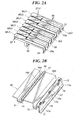
- FIG. 2A is a perspective view of a key unit;
- FIG. 2B is a perspective view of a key frame;
- FIG. 3 is a perspective view of a black key unit;
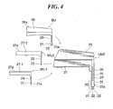
- FIG. 4 is a side view showing rear halves of white key units, the black key unit, and the key unit;
- FIG. 5 is a side view showing essential parts of a rear stopper and a contact portion according to a modification of the first embodiment;
- FIG. 6 is a sectional view showing an essential part of an electronic keyboard instrument to which is applied a keyboard structure according to a second embodiment of the present invention;
- FIG. 7A is a sectional view showing an essential part of an electronic keyboard instrument to which is applied a keyboard structure according to a third embodiment of the present invention;
- FIG. 7B is a sectional view showing an essential part of an electronic keyboard instrument to which is applied a keyboard structure according to a fourth embodiment of the present invention;
- FIG. 8A is a sectional view showing an essential part of an electronic keyboard instrument to which is applied a keyboard structure according to a fifth embodiment of the present invention; and
- FIG. 8B is a sectional view showing an essential part of an electronic keyboard instrument to which is applied a keyboard structure according to a sixth embodiment of the present invention.
- The present invention will now be described in detail below with reference to the drawings showing preferred embodiments thereof.
- [First Embodiment]
- FIG. 1 is a sectional view showing an essential part of an electronic keyboard instrument to which is applied a keyboard structure according to a first embodiment of the present invention. This keyboard instrument includes a
key frame 10 mounted with a key unit UNT. In the following, a side of the keyboard instrument toward a player (the left side in FIG. 1) will be referred to as the front side, and the left-to-right direction will be determined in reference to the player. It should be noted that an illustration of an instrument body that supports thekey frame 10 is omitted. - FIG. 2A is a perspective view of the key unit UNT, and FIG. 2B is a perspective view of the
key frame 10. As shown in FIG. 2A, the key unit UNT is constructed on an octave basis, for instance, to have one or more one-octave parts and includes first and second white key units WU1, WU2 each having a plurality of white keymain bodies 27 and a black key unit BU having a plurality of black keymain bodies 28, these three units being assembled in a stacked relation. Thekey frame 10 is formed by resin into one piece or by a composite of resin and non-resin (metal or the like), and extends over the entire width of all keys. In FIG. 2B, only one-octave part of thekey frame 10 is shown. - As shown in FIGS. 1 and 2B, at a lower part of a
front portion 10c of thekey frame 10, there is provided akey depression stopper 11 adapted to restrict lower limit positions (key depression end positions) of the white and black keymain bodies intermediate portion 10b of thekey frame 10 disposed at an intermediate position in the front-to-rear direction, anupper limit stopper 14 is provided for restricting upper limit positions (key depression initial positions) of the white and black key main bodies at the time of key release, i.e., in a key-nondepressed state. The lower andupper stoppers - At an upper front part of the
intermediate portion 10b, there is integrally formed a ridge-like protrusion 41 in the key arrangement direction, and arear stopper 42 is fixedly provided by, for example, being fixed so as to be in contact with a front surface of the ridge-like protrusion 41. As will be described later, therear stopper 42 acts to restrict rearward displacements of the white and black keymain bodies intermediate portion 10b of thekey frame 10 is formed at its front end withnotches 10d respectively corresponding to the white and black keymain bodies - As shown in FIG. 1, at the
intermediate portion 10b of thekey frame 10, there are disposed two-make-contact key depression switches 12, 13, which respectively correspond to the white and black keymain bodies key frame 10 to which the key depression switches 12, 13 are mounted. Thekey frame 10 has itsrear portion 10a formed with a recessedgroove 15 over the entire key width, which fittedly supports a common-to-all-keys base end 20 (a base end common to all the keys) of the key unit UNT. The recessedgroove 15 is a substantially U-shape as seen from side and has an opening that opens upward. - FIG. 3 is a perspective view of the black key unit BU, and FIG. 4 is a side view showing rear halves of the white key units WU1, WU2, the black key unit BU, and the key unit UNT
- As shown in FIGS. 2A, 3 and 4, the black key unit BU includes black key
main bodies 28 respectively corresponding to tone pitches C#, D#, F#, G#, and A#. As shown in FIGS. 2A and 4, the first white key unit WU1 includes white key main bodies 27-1 corresponding to tone pitches C, E, G, and B, and the second white key unit WU2 includes white key main bodies 27-2 corresponding to tone pitches D, F, and A. In the following, the white key main bodies 27-1, 27-2 are simply referred to as "white keymain bodies 27" when they are referred to without distinction. The white and black keymain bodies key depression surfaces - As shown in FIGS. 1 to 3, the white and black key
main bodies stopper contact member key depression stopper 11 at the time of key depression. Thestopper contact members notches 10d in theintermediate portion 10b of the key frame 10 (refer to FIGS. 1 and 2B). - As shown in FIGS. 3 and 4, thin plate-
like hinges 26 are extended downward from rear ends of the black keymain bodies 28 of the black key unit BU. These hinges 26 are connected at their lower ends to a common-to-black-keys base end 23 (a base end common to the black keys) having a length corresponding to one octave. The hinges 26 and the common-to-black-keys base end 23 are the same in thickness and extend in a vertical direction and in parallel to the key arrangement direction (the left-to-right direction). The black keymain bodies 28 are supported via thehinges 26 for pivotal motion relative to the common-to-black-keys base end 23, serving as a key fulcrum, in the vertical direction (in the key depression/release direction). The common-to-black-keys base end 23 is formed at its left and right ends with temporaryjoint members 31 that prevent the assembled key unit UNT from being disassembled in the left-to-right direction. Each temporaryjoint member 31 is formed into a plate-like shape and extended forward from the left or right end of the common-to-black-keys base end 23. - As shown in FIG. 4 and as in the case of the black key unit BU, hinges 24 are extended downward from rear ends of the white key main bodies 27-1 of the first white key unit WU1. The hinges 24 are connected at lower ends thereof to a first common-to-white-keys base end 21 (a base end common to white keys corresponding to tone pitches C, E, G, and B).
Hinges 25 are extended downward from rear ends of the white key main bodies 27-2 of the second white key unit WU2. The hinges 25 are connected at lower ends to a second common-to-white-keys base end 22 (a base end common to white keys corresponding to tone pitches D, F, and A). Each white keymain body 27 is supported via a correspondinghinge keys base end keys base end 21, and thehinges 25 and the second common-to-white-keys base end 22 are the same in thickness and extend vertically and perpendicular to thekey depression surfaces 27a and parallel to the key arrangement direction. - In assembling the first and second white key units WU1, WU2 and the black key unit BU into the key unit UNT, the first and second common-to-white-keys base ends 21, 22 and the common-to-black-
keys base end 23, which are common base ends of the units WU1, WU2 and BU, are sequentially disposed in a stacked relation from the front side of the keyboard instrument, as shown in FIG. 4. The common base ends 21 to 23 are made in contact with one another and stacked together to form the above described common-to-all-keys base end 20. - When any of the key depression switches 12, 13 is depressed or released by a corresponding one of the white and black key
main bodies - As shown in FIG. 2B, the
key frame 10 is integrally formed at itsrear portion 10a withelastic members 17 so as to project therefrom in the key arrangement direction at a plurality of locations (for example, three locations) on the front side of therear portion 10a with respect to the recessedgroove 15. Theelastic members 17 are formed so as to extend upward and formed thin along the key arrangement direction in such a manner that upper ends of the elastic members can be deformed in the front-to-back direction. Theelastic members 17 are each integrally formed at a rear surface thereof with aprotrusion 17a, which is formed in a circular shape as seen from rear so as to project from the elastic member (refer to FIG. 2B). Thekey frame 10 is integrally formed withelastic members 16 so as to project therefrom in the key arrangement direction at a plurality of locations (for example, two locations) on the rear side of therear portion 10a with respect to the recessedgroove 15. Theelastic members 16 each have an upper end thereof that can be deformed in the front-to-back direction. - The key unit UNT is assembled in advance and then mounted to the
key frame 10. First, the second common-to-white-keys base end 22 of the second white key unit WU2 is superimposed on the rear surface of the first common-to-white-keys base end 21 of the first white key unit WU1, and theprotrusions 21a are caused to be fitted into the fitting holes, not shown, of the second common-to-white-keys base end 22. Then, the common-to-black-keys base end 23 of the back key unit BU is superimposed on the rear surface of the second common-to-white-keys base end 22 and is positioned so that the common base ends 21, 22 are held between the temporaryjoint members 31 disposed on the both sides thereof. - Then, the common-to-all-
keys base end 20 of the key unit UNT, which is comprised of the white and black key units stacked in three layers, is fitted to the recessedgroove 15 of thekey frame 10 from above. As a result, theprotrusions 17a (see, FIG. 2B) of theelastic member 17 are fitted in the fitting holes, not shown, of the first common-to-white-keys base end 21 and theprotrusions 23a (see, FIGS. 3 and 4) of the common-to-black-keys base end 23 are fitted into the fitting holes, not shown, of theelastic members 16. At that time, theelastic members key frame 10 is completed. - When a key depression operation is performed after assembly of the key unit UNT to the
key frame 10, a corresponding one of the white and blackkey bodies hinge stopper contact member lower limit stopper 11, whereby a key depression completed state is reached. When a key depression is released, the white or black keymain body hinge stopper contact member upper limit stopper 14. Therefore, the white or black keymain body - The rear stopper 42 (see FIGS. 1 and 2B) is formed by an elastic member with shock-absorbing property, such as felt. There may be provided rear stoppers respectively corresponding to the white and black key
main bodies main bodies main bodies contact portions stopper contact members 29, 30 (see FIG. 1) are in light contact with front surface of therear stopper 42. Thestopper contact members notches 10d, and cannot be in direct contact with thekey frame 10 during the entire key depression stroke. - Since the
hinges 24 to 26 extend downward at positions below thekey depression surfaces key depression surfaces key depression surfaces key depression surface - In the case of hinge-type keys, the key depression point is displaced also by hinge deformation. For example, in the case of a horizontal hinge, the key depression point is additionally displaced rearward when a front portion of the hinge is deformed downward. Also in an arrangement having upwardly extending hinges, a rearward displacement of the key depression point is caused when a lower portion of a hinge is deformed rearward. From the viewpoint of music performance, it is preferable that the rearward displacement of the key depression point be made small.
- In this embodiment, an upper portion of the
hinge hinge contact portions stopper contact members main bodies - As a result, the distance in the front-to-rear direction between the front surface of the
rear stopper 42 and thecontact portions main body key depression surfaces - Since upper ends of the
hinges 24 to 26 can be deformed in the front-to-rear direction, the white and black keymain bodies hinges 24 to 26. If no countermeasure is taken, the keymain bodies hinges 24 to 26. - In this embodiment, however, in a key-nondepressed state, the
contact portions rear stopper 42. When a rearwardly exerting force is applied to any of the keymain bodies rear stopper 42 to thecontact portion main body corresponding hinge contact portions stopper contact members main bodies - From the viewpoint of preventing plastic deformation of the
hinges 24 to 26, thecontact portions rear stopper 42. In other words, each of the stopper contact members may be configured so that the contact portion thereof is disposed close to the rear stopper with a slight gap (preferably as small as possible) therebetween for contact with the rear stopper when the corresponding keymain body rear stopper 42 has elasticity, each of thecontact portions rear stopper 42 when the concerned key is in the key depression initial position. In the assembled keyboard structure, there may be a gap between the contact portions and the rear stopper. Occurrence of such a gap due to secular change is also acceptable. Needless say, rearward displacements of the keymain bodies - In the course of the key depression/release stroke, the
contact portion rear stopper 42, but a gap therebetween does not increase to a large extent. As a result, when the keymain body contact portion rear stopper 42, whereby the worst case that thehinge - According to this embodiment, the
hinges 24 to 26 are extended in the key unit UNT in the direction perpendicular to thekey depression surfaces 27a and parallel to the vertical direction and the key arrangement direction. Therefore, the dimension of the key unit UNT in the key longitudinal direction can be reduced, making it possible to suppress the depth dimension of the keyboard instrument. - In a key-nondepressed state, the
contact portions rear stopper 42. This contacting arrangement makes it possible to suppress rearward displacements of the keymain bodies hinges 24 to 26. - When any of the key
main bodies corresponding contact portion main body rear stopper 42 and thecontact portion rear stopper 42 and thecontact portions main bodies hinges 24 to 26. - It should be noted that in order to solely prevent the key depression operation from being hindered while suppressing rearward displacements of the key
main bodies contact portions rear stopper 42 when they are in a position other than the key depression initial position. Even with an arrangement in which the key main bodies are not displaced forwardly in the forward stroke of key depression, it is possible by well designing the shapes of the rear stopper and the contact portions to arrange thecontact portions rear stopper 42 when the keys are in a key-nondepressed state. An example is shown in FIG. 5, and an illustrated concept can be applied to arrangements according to a second embodiment and subsequent embodiments, which will be described below. - FIG. 5 is a side view showing essential parts of a rear stopper and a contact portion according to a modification of the first embodiment. FIG. 5 shows by way of example an arrangement in which the shape of the
rear stopper 42 and the shape of thecontact portion 29a of thestopper contact member 29 of the white key main body 27-1 are modified. This modification can also be applied to the white key main body 27-2 and the black keymain body 28. - In the arrangement shown in FIG. 1, the front surface of the
rear stopper 42 and the rear surface of thecontact portion 29a of thestopper contact member 29 are formed to extend parallel to the vertical direction. On the other hand, in this modification, thefront surface 42a of therear stopper 42 is formed so as to be forwardly inclined toward upward and thecontact portion 29a is correspondingly formed to be forwardly inclined toward upward, so that the rear stopper and the contact portion are in face contact with each other in a key-nondepressed state, as shown in FIG. 5. Such an inclined arrangement can also be adopted in the first embodiment. - In this modification, as shown in FIG. 5, the
hinge 24 is not extended downward but upward from a rear end of the white key main body 27-1, and thecommon base end 21 is positioned above thekey depression surface 27a. When considering a movement in the front-to-rear direction, the key depression point on thekey depression surface 27a moves rearward with advancement of key depression (refer to a two-dotted chain line in FIG. 5). With such a construction, it is possible to dispose thecontact portion 29a of thestopper contact member 29 close to or in contact with thefront surface 42a of therear stopper 42 in a key-nondepressed state but separated away therefrom in a key-depressed state by the action of the inclination provided to the front surface of the stopper and the contact portion of the contact member. - In the first embodiment, rearward displacements of the key
main bodies rear stopper 42 and thecontact portions stopper contact members main bodies
However, these paired members are different from those of the first embodiment. - [Second Embodiment]
- FIG. 6 is a sectional view showing an essential part of an electronic keyboard instrument to which is applied a keyboard structure according to a second embodiment of the present invention. This embodiment only differs from the first embodiment in that a
rear stopper 51 is provided instead of the above described ridge-like protrusion 41 and therear stopper 42 which are eliminated in this embodiment and in that the keymain bodies contact portion 43. Other constructions of this embodiment are the same as the first embodiment. - The
rear stopper 51 is made of the same or similar material to that of therear stopper 42, and is fixedly provided, by for example being fixed, on an upper rear part of theintermediate portion 10a of theframe 10. Thecontact portion 43 of each keymain body main body contact portion 43 is in light contact with a front surface of therear stopper 51. In a forward stroke of key depression, thecontact portion 43 is separated from therear stopper 51 with pivotal motion of the corresponding keymain body 27 or 28 (refer to a two-dotted chain line in FIG. 6). - This embodiment can achieve the same or similar effects as the first embodiment.
- [Third Embodiment]
- FIG. 7A is a sectional view showing an essential part of an electronic keyboard instrument to which is applied a keyboard structure according to a third embodiment of the present invention. This embodiment only differs from the first embodiment in that key guides 44 and
contact portions 45 are provided, with the other constructions being the same as or similar to the first embodiment. - The key guides 44 are integrally formed in those portions of the
key frame 10 which are in the vicinity of thenotches 10d of thekey frame 10 on the front side of thenotches 10d, so as to extend upward. The key guides 44 are each slidably fitted between a corresponding pair ofstopper contact members contact portions 45 are integrally formed in the keymain bodies stopper contact members contact portion 45 is formed into a rib shape extending parallel to the vertical direction and the key arrangement direction from an upper portion of the corresponding keymain body stopper contact members - In the key depression/release stroke, a pair of
stopper contact members key guide 44 to thereby guide a pivotal motion of the corresponding keymain body contact portion 45 is in light contact with a front surface of thekey guide 44. In a forward stroke of key depression, thecontact portion 45 is gradually separated from thekey guide 44 with a pivotal motion of the keymain body main body rear stopper 42 and thecontact portion key guide 44, thecontact portion 45, therear stopper 42 and thecontact portion main bodies - With this embodiment, the same or similar effects as the first embodiment can be attained, and further rearward displacements of the key
main bodies - It should be noted that rearward displacements of the key
main bodies key guide 44 and thecontact portion 45, with therear stopper 42 eliminated. Even with such an arrangement, thekey guide 44 has both the function of guiding key depressing operation and the function of restricting rearward displacements of the keymain bodies - [Fourth Embodiment]
- FIG. 7B is a sectional view showing an essential part of an electronic keyboard instrument to which is applied a keyboard structure according to a fourth embodiment of the present invention. This embodiment differs from the first embodiment only in that the ridge-
like protrusion 41 and therear stopper 42 are eliminated and instead a ridge-like protrusion 47 is provided, and in that instead of theupper stopper 14 there is provided an upper limit/rear stopper 48 made of the same material. In other respects, this embodiment is the same in construction as the first embodiment. - The ridge-
like protrusion 47 is integrally formed in a front lower part of theintermediate portion 10b of thekey frame 10 so as to extend in the key arrangement direction. The upper limit/rear stopper 48 is fixedly provided, for example by fixing, in the lower front part of theintermediate portion 10b for contact with a front surface of the ridge-like protrusion 47. - As with the
upper stopper 14, the upper limit/rear stopper 48 acts to restrict the key depression initial position of the keymain bodies rear stopper 48 has the function of therear stopper 42. Specifically, in a key-nondepressed state, rear parts of thecontact portions rear stopper 48. In a forward stroke of key depression, with a pivotal motion of the keymain body contact portion - This embodiment can attain the same or similar effects attained by the first embodiment. Furthermore, the upper limit/
rear stopper 48 have both the function of the key depression initial stopper and the function of restricting rearward displacements of the keymain bodies - [Fifth Embodiment]
- FIG. 8A is a sectional view showing an essential part of an electronic keyboard instrument to which is applied a keyboard structure according to a fifth embodiment of the present invention. This embodiment differs from the first embodiment only in that the
lower stopper 11 is eliminated and in that instead of therear stopper 42 a lower limit/rear stopper 49 is provided that is made of the same material as therear stopper 42. The other constructions of this embodiment are the same as the first embodiment. - The lower limit/
rear stopper 49 is fixedly provided, by for example fixing, at an upper front part of theintermediate portion 10b for contact with a front surface of the ridge-like protrusion 41, and has a larger height than therear stopper 42. The lower limit/rear stopper 49 is adapted for contact with lower surfaces of forwardly pivoted keymain bodies lower stopper 11, the key depression end positions of the keymain bodies rear stopper 49 has the function of therear stopper 42. - Specifically, in a key-nondepressed state, rear parts of the
contact portions rear stopper 49. In a forward stroke of key depression, with a pivotal motion of the keymain body corresponding contact portion rear stopper 49. - This embodiment can achieve the same effects as the first embodiment. In addition, this embodiment includes the lower limit/
rear stopper 49 having both the function of a key depression stopper and the function of restricting rearward displacements of the keymain bodies - [Six Embodiment]
- In the first to fifth embodiments, the
key frame 10 is provided with an element adapted for substantial contact with the keymain bodies main bodies - FIG. 8B is a sectional view showing a rear portion of a key of an electronic keyboard instrument to which is applied a keyboard structure according to a sixth embodiment of the present invention. This embodiment differs from the first embodiment only in that the ridge-
like protrusion 41 and therear stopper 42 are removed, andrear stoppers panel 50 which is a part of the instrument body. This embodiment is the same or similar to the first embodiment in other constructions. - The
rear stoppers rear stopper 42, and are fixedly provided by for example fixing to thepanel 50 in a gap between thepanel 50 and rear end surfaces 27b, 28b of the keymain bodies main bodies rear stoppers main body rear end surface main body rear stoppers - This embodiment can achieve the same or similar effects as the first embodiment.
- It should be noted that from the viewpoint of suppressing rearward displacements of the key
main bodies rear stopper 42 adapted for contact with thecontact portions main bodies key frame 10 and the instrument body. From the viewpoint of stably suppressing rearward displacements of the keymain bodies contact portions rear stopper 42 be disposed close to the keymain bodies main bodies - Furthermore, among various paired elements adapted for contact with each other as described in the embodiments, the keyboard structure may be provided with two or more sets of paired elements. For example, there may be included both the combination of the
contact portions rear stoppers 52, 53 (shown in the sixth embodiment in FIG. 8B). - It should be noted that the
rear stoppers rear stoppers 48, and the lower limit/rear stopper 49 may be provided in each individual key or may be integrally provided in each of one or more predetermined key groups. - It should also be noted that the contact relation between the
contact portions rear stopper 42 or between other paired elements is not limited to a face contact but may be a line contact or a point contact. - In the above described embodiments, the
rear stopper 42 and the like are made of felt or the like to have a shock-absorbing property. This is not limitative. Alternatively, a member having ashock-absorbing property may be provided or fixed in those parts of the keymain bodies 27, 28 (such as thecontact portions rear stopper 42 or the like. In that case, therear stopper 42 or the like may be formed integrally with thekey frame 10. - In the above described embodiments, the
hinges 24 to 26 are extended in the vertical direction. From the viewpoint of suppressing the depth dimension of the keyboard instrument as small as possible and improving the loci of thekey depression surfaces key depression surface 27a and parallel to the key arrangement direction. For example, therefore, the hinges may be obliquely inclined downward toward the rear. The common base ends may not be extended parallel to thehinges 24 to 26 and may not be the same in thickness as the hinges. There may be a step difference between the common base ends and thehinges 24 to 26 as viewed in the front-to-rear direction. - In the above described embodiments, there have been described arrangements that suppress rearward displacements of the key
main bodies - It should be noted that in the illustrated examples the keys are unified into a part of the key unit UNT. However, the present invention is also applicable to a keyboard instrument having individual keys.
- It should also be noted that the present invention is applicable to a keyboard instrument provided with hammers each adapted to be pivoted interlockingly with a corresponding key to thereby add appropriate inertia to the key which is depressed.
Claims (6)
- A keyboard structure of an electronic keyboard instrument, comprising:keys having key main bodies thereof connected through thin plate-like hinges to base ends at a rear of the keys and adapted to be pivoted about the base ends as key fulcrums in a key depression/release direction;a key frame fixedly provided relative to an instrument body and adapted to fixedly support the base ends of said keys;a stopper fixedly provided in at least one of the instrument body and said key frame; andstopper contact portions provided in the key main bodies and disposed close to or in contact with said stopper in a key-nondepressed state,wherein said hinges of the keys are formed to extend in a direction to cross key depression surfaces of the key main bodies and parallel to a key arrangement direction, and
wherein when any of the key main bodies is urged rearward at least in the key-nondepressed state, the stopper contact portion corresponding to the urged key main body is made in contact with said stopper to thereby restrict a rearward displacement of the urged key main body. - The keyboard structure according to claim 1,
wherein a distance between the stopper and each of the stopper contact portions during a key depression/release stroke is made minimum in the key-nondepressed state. - The keyboard structure according to claim 2,
wherein the base ends are located below the key depression surfaces of the key main bodies in the key-nondepressed state, and the stopper contact portions are each adapted to be displaced forwardly together with a corresponding one of the key main bodies with a forward pivotal motion of the key main body in a key depression stroke, so that the distance between the stopper and the stopper contact portion in a front-to-rear direction increases with the forward pivotal motion of the key main body during the key depression stroke. - The keyboard structure according to claim 1,
wherein said stopper is provided in the key frame and formed to have a function of a key guide to guide a key depression/release action of the key main bodies. - The keyboard structure according to claim 1,
wherein said stopper is provided in the key frame and formed to have a function of a key depression initial stopper adapted for contact with the key main body reversely pivoted in the key depression stroke to thereby restrict a key depression initial position of the keys. - The keyboard structure according to claim 1,
wherein the stopper is provided in the key frame and formed to have a function of a key depression end stopper adapted for contact with the key main body forwardly pivoted in the key depression stroke to thereby restrict a key depression end position of the keys.
Applications Claiming Priority (1)
| Application Number | Priority Date | Filing Date | Title |
|---|---|---|---|
| JP2006196011A JP4780461B2 (en) | 2006-07-18 | 2006-07-18 | Keyboard structure of electronic keyboard instrument |
Publications (2)
| Publication Number | Publication Date |
|---|---|
| EP1881481A1 true EP1881481A1 (en) | 2008-01-23 |
| EP1881481B1 EP1881481B1 (en) | 2015-02-25 |
Family
ID=38610486
Family Applications (1)
| Application Number | Title | Priority Date | Filing Date |
|---|---|---|---|
| EP07112324.4A Not-in-force EP1881481B1 (en) | 2006-07-18 | 2007-07-12 | Keyboard structure of electronic keyboard instrument |
Country Status (4)
| Country | Link |
|---|---|
| US (1) | US7678981B2 (en) |
| EP (1) | EP1881481B1 (en) |
| JP (1) | JP4780461B2 (en) |
| CN (1) | CN101110211B (en) |
Cited By (1)
| Publication number | Priority date | Publication date | Assignee | Title |
|---|---|---|---|---|
| EP2180462A3 (en) * | 2008-09-25 | 2010-12-15 | Yamaha Corporation | Keyboard apparatus |
Families Citing this family (9)
| Publication number | Priority date | Publication date | Assignee | Title |
|---|---|---|---|---|
| US7696424B2 (en) * | 2006-10-26 | 2010-04-13 | Yamaha Corporation | Keyboard apparatus of electronic musical instrument |
| JP2009014973A (en) * | 2007-07-04 | 2009-01-22 | Yamaha Corp | Keyboard apparatus of electronic musical instrument |
| US7750222B2 (en) * | 2007-09-21 | 2010-07-06 | Yamaha Corporation | Keyboard apparatus of electronic musical instrument |
| JP5423061B2 (en) * | 2009-03-05 | 2014-02-19 | ヤマハ株式会社 | Keyboard device |
| JP5861859B2 (en) * | 2011-07-01 | 2016-02-16 | カシオ計算機株式会社 | Pedal device and keyboard instrument |
| JP6091390B2 (en) * | 2013-09-26 | 2017-03-08 | 株式会社河合楽器製作所 | Keyboard device for keyboard instrument |
| JP6595940B2 (en) * | 2016-03-22 | 2019-10-23 | 株式会社河合楽器製作所 | Key guide structure of keyboard instrument |
| JP6879019B2 (en) * | 2017-04-04 | 2021-06-02 | ヤマハ株式会社 | Keyboard device |
| CN209993339U (en) * | 2019-05-07 | 2020-01-24 | 得理电子(上海)有限公司 | Keyboard assembly |
Citations (11)
| Publication number | Priority date | Publication date | Assignee | Title |
|---|---|---|---|---|
| US4914999A (en) * | 1987-09-04 | 1990-04-10 | Yamaha Corporation | Keyboard assembly for forming keyboard apparatus of electronic musical instrument |
| US5821443A (en) * | 1996-01-29 | 1998-10-13 | Yamaha Corporation | Keyboard apparatus with an improved mass member support system |
| US5895875A (en) * | 1994-03-24 | 1999-04-20 | Yamaha Corporation | Keyboard assembly for electronic musical instrument |
| EP1076132A1 (en) | 1999-08-13 | 2001-02-14 | Fort James France | Process for fixing of mineral filler on cellulosic fibres and paper manufacturing process |
| JP2001125573A (en) * | 1999-10-25 | 2001-05-11 | Casio Comput Co Ltd | Keyboard device |
| EP1114219A1 (en) | 1998-02-20 | 2001-07-11 | L'air Liquide, Societe Anonyme Pour L'etude Et L'exploitation Des Procedes Georges Claude | Calcium carbonate synthesis method and resulting product |
| JP2001296868A (en) * | 2000-04-13 | 2001-10-26 | Matsushita Electric Ind Co Ltd | Electronic keyboard instrument |
| JP2004117528A (en) * | 2002-09-24 | 2004-04-15 | Yamaha Corp | Operator guide structure of musical instrument |
| JP2005189511A (en) * | 2003-12-25 | 2005-07-14 | Yamaha Corp | Key guide structure of keyboard device |
| JP2007163526A (en) * | 2005-12-09 | 2007-06-28 | Yamaha Corp | Key guide structure of electronic keyboard musical instrument |
| EP2262948A2 (en) | 2008-02-22 | 2010-12-22 | UPM-Kymmene Oyj | A method for crystallizing a filler in connection with a fiber web process, and an approach system for a fiber web machine |
Family Cites Families (3)
| Publication number | Priority date | Publication date | Assignee | Title |
|---|---|---|---|---|
| JP2628656B2 (en) | 1987-10-01 | 1997-07-09 | ヤマハ株式会社 | Keyboard device |
| KR970006172B1 (en) * | 1992-08-10 | 1997-04-24 | 야마하 가부시키가이샤 | Keyboard device for electronic musical instrument |
| JP2002369904A (en) | 2001-06-13 | 2002-12-24 | Sigma Solutions:Kk | Golf information management system |
-
2006
- 2006-07-18 JP JP2006196011A patent/JP4780461B2/en not_active Expired - Fee Related
-
2007
- 2007-07-12 EP EP07112324.4A patent/EP1881481B1/en not_active Not-in-force
- 2007-07-13 US US11/827,785 patent/US7678981B2/en active Active
- 2007-07-18 CN CN2007101366250A patent/CN101110211B/en not_active Expired - Fee Related
Patent Citations (11)
| Publication number | Priority date | Publication date | Assignee | Title |
|---|---|---|---|---|
| US4914999A (en) * | 1987-09-04 | 1990-04-10 | Yamaha Corporation | Keyboard assembly for forming keyboard apparatus of electronic musical instrument |
| US5895875A (en) * | 1994-03-24 | 1999-04-20 | Yamaha Corporation | Keyboard assembly for electronic musical instrument |
| US5821443A (en) * | 1996-01-29 | 1998-10-13 | Yamaha Corporation | Keyboard apparatus with an improved mass member support system |
| EP1114219A1 (en) | 1998-02-20 | 2001-07-11 | L'air Liquide, Societe Anonyme Pour L'etude Et L'exploitation Des Procedes Georges Claude | Calcium carbonate synthesis method and resulting product |
| EP1076132A1 (en) | 1999-08-13 | 2001-02-14 | Fort James France | Process for fixing of mineral filler on cellulosic fibres and paper manufacturing process |
| JP2001125573A (en) * | 1999-10-25 | 2001-05-11 | Casio Comput Co Ltd | Keyboard device |
| JP2001296868A (en) * | 2000-04-13 | 2001-10-26 | Matsushita Electric Ind Co Ltd | Electronic keyboard instrument |
| JP2004117528A (en) * | 2002-09-24 | 2004-04-15 | Yamaha Corp | Operator guide structure of musical instrument |
| JP2005189511A (en) * | 2003-12-25 | 2005-07-14 | Yamaha Corp | Key guide structure of keyboard device |
| JP2007163526A (en) * | 2005-12-09 | 2007-06-28 | Yamaha Corp | Key guide structure of electronic keyboard musical instrument |
| EP2262948A2 (en) | 2008-02-22 | 2010-12-22 | UPM-Kymmene Oyj | A method for crystallizing a filler in connection with a fiber web process, and an approach system for a fiber web machine |
Cited By (2)
| Publication number | Priority date | Publication date | Assignee | Title |
|---|---|---|---|---|
| EP2180462A3 (en) * | 2008-09-25 | 2010-12-15 | Yamaha Corporation | Keyboard apparatus |
| US8003871B2 (en) | 2008-09-25 | 2011-08-23 | Yamaha Corporation | Keyboard apparatus |
Also Published As
| Publication number | Publication date |
|---|---|
| US20080017016A1 (en) | 2008-01-24 |
| CN101110211B (en) | 2012-05-30 |
| CN101110211A (en) | 2008-01-23 |
| JP4780461B2 (en) | 2011-09-28 |
| JP2008026403A (en) | 2008-02-07 |
| US7678981B2 (en) | 2010-03-16 |
| EP1881481B1 (en) | 2015-02-25 |
Similar Documents
| Publication | Publication Date | Title |
|---|---|---|
| US7678981B2 (en) | Keyboard structure of electronic keyboard instrument | |
| US7427723B2 (en) | Keyboard apparatus | |
| US8093480B2 (en) | Keyboard device for electronic keyboard instrument | |
| US8003871B2 (en) | Keyboard apparatus | |
| US8158876B2 (en) | Keyboard apparatus | |
| US9082372B2 (en) | Keyboard device for keyboard instrument | |
| US7897860B2 (en) | Keyboard apparatus | |
| US10762884B2 (en) | Keyboard device for electronic keyboard instrument and keyframe front for keyboard instrument | |
| US7544876B2 (en) | Keyboard apparatus of electronic keyboard instrument | |
| US20230101297A1 (en) | Keyboard device for keyboard instrument | |
| US20240112660A1 (en) | Keyboard device for keyboard instrument | |
| US9940916B2 (en) | Key guide structure for keyboard instrument | |
| JP2023090912A (en) | keyboard instrument | |
| EP1622126A1 (en) | Keyboard device for keyboard instrument | |
| US20240112658A1 (en) | Keyboard device for keyboard instrument | |
| EP1746571B1 (en) | Keyboard apparatus | |
| US7265288B2 (en) | Key structure | |
| JP7206648B2 (en) | keyboard instrument | |
| JP7616236B2 (en) | Keyboard device |
Legal Events
| Date | Code | Title | Description |
|---|---|---|---|
| PUAI | Public reference made under article 153(3) epc to a published international application that has entered the european phase |
Free format text: ORIGINAL CODE: 0009012 |
|
| AK | Designated contracting states |
Kind code of ref document: A1 Designated state(s): AT BE BG CH CY CZ DE DK EE ES FI FR GB GR HU IE IS IT LI LT LU LV MC MT NL PL PT RO SE SI SK TR |
|
| AX | Request for extension of the european patent |
Extension state: AL BA HR MK YU |
|
| 17P | Request for examination filed |
Effective date: 20080718 |
|
| AKX | Designation fees paid |
Designated state(s): AT BE BG CH CY CZ DE DK EE ES FI FR GB GR HU IE IS IT LI LT LU LV MC MT NL PL PT RO SE SI SK TR |
|
| 17Q | First examination report despatched |
Effective date: 20131022 |
|
| GRAP | Despatch of communication of intention to grant a patent |
Free format text: ORIGINAL CODE: EPIDOSNIGR1 |
|
| INTG | Intention to grant announced |
Effective date: 20141008 |
|
| GRAS | Grant fee paid |
Free format text: ORIGINAL CODE: EPIDOSNIGR3 |
|
| GRAA | (expected) grant |
Free format text: ORIGINAL CODE: 0009210 |
|
| AK | Designated contracting states |
Kind code of ref document: B1 Designated state(s): AT BE BG CH CY CZ DE DK EE ES FI FR GB GR HU IE IS IT LI LT LU LV MC MT NL PL PT RO SE SI SK TR |
|
| REG | Reference to a national code |
Ref country code: GB Ref legal event code: FG4D |
|
| REG | Reference to a national code |
Ref country code: CH Ref legal event code: EP |
|
| REG | Reference to a national code |
Ref country code: IE Ref legal event code: FG4D |
|
| REG | Reference to a national code |
Ref country code: DE Ref legal event code: R096 Ref document number: 602007040322 Country of ref document: DE Effective date: 20150409 |
|
| REG | Reference to a national code |
Ref country code: AT Ref legal event code: REF Ref document number: 712563 Country of ref document: AT Kind code of ref document: T Effective date: 20150415 |
|
| REG | Reference to a national code |
Ref country code: NL Ref legal event code: VDEP Effective date: 20150225 |
|
| REG | Reference to a national code |
Ref country code: AT Ref legal event code: MK05 Ref document number: 712563 Country of ref document: AT Kind code of ref document: T Effective date: 20150225 |
|
| REG | Reference to a national code |
Ref country code: LT Ref legal event code: MG4D |
|
| PG25 | Lapsed in a contracting state [announced via postgrant information from national office to epo] |
Ref country code: ES Free format text: LAPSE BECAUSE OF FAILURE TO SUBMIT A TRANSLATION OF THE DESCRIPTION OR TO PAY THE FEE WITHIN THE PRESCRIBED TIME-LIMIT Effective date: 20150225 Ref country code: FI Free format text: LAPSE BECAUSE OF FAILURE TO SUBMIT A TRANSLATION OF THE DESCRIPTION OR TO PAY THE FEE WITHIN THE PRESCRIBED TIME-LIMIT Effective date: 20150225 Ref country code: SE Free format text: LAPSE BECAUSE OF FAILURE TO SUBMIT A TRANSLATION OF THE DESCRIPTION OR TO PAY THE FEE WITHIN THE PRESCRIBED TIME-LIMIT Effective date: 20150225 Ref country code: LT Free format text: LAPSE BECAUSE OF FAILURE TO SUBMIT A TRANSLATION OF THE DESCRIPTION OR TO PAY THE FEE WITHIN THE PRESCRIBED TIME-LIMIT Effective date: 20150225 |
|
| PG25 | Lapsed in a contracting state [announced via postgrant information from national office to epo] |
Ref country code: IS Free format text: LAPSE BECAUSE OF FAILURE TO SUBMIT A TRANSLATION OF THE DESCRIPTION OR TO PAY THE FEE WITHIN THE PRESCRIBED TIME-LIMIT Effective date: 20150625 Ref country code: LV Free format text: LAPSE BECAUSE OF FAILURE TO SUBMIT A TRANSLATION OF THE DESCRIPTION OR TO PAY THE FEE WITHIN THE PRESCRIBED TIME-LIMIT Effective date: 20150225 Ref country code: GR Free format text: LAPSE BECAUSE OF FAILURE TO SUBMIT A TRANSLATION OF THE DESCRIPTION OR TO PAY THE FEE WITHIN THE PRESCRIBED TIME-LIMIT Effective date: 20150526 Ref country code: AT Free format text: LAPSE BECAUSE OF FAILURE TO SUBMIT A TRANSLATION OF THE DESCRIPTION OR TO PAY THE FEE WITHIN THE PRESCRIBED TIME-LIMIT Effective date: 20150225 |
|
| PG25 | Lapsed in a contracting state [announced via postgrant information from national office to epo] |
Ref country code: NL Free format text: LAPSE BECAUSE OF FAILURE TO SUBMIT A TRANSLATION OF THE DESCRIPTION OR TO PAY THE FEE WITHIN THE PRESCRIBED TIME-LIMIT Effective date: 20150225 |
|
| PG25 | Lapsed in a contracting state [announced via postgrant information from national office to epo] |
Ref country code: CZ Free format text: LAPSE BECAUSE OF FAILURE TO SUBMIT A TRANSLATION OF THE DESCRIPTION OR TO PAY THE FEE WITHIN THE PRESCRIBED TIME-LIMIT Effective date: 20150225 Ref country code: SK Free format text: LAPSE BECAUSE OF FAILURE TO SUBMIT A TRANSLATION OF THE DESCRIPTION OR TO PAY THE FEE WITHIN THE PRESCRIBED TIME-LIMIT Effective date: 20150225 Ref country code: EE Free format text: LAPSE BECAUSE OF FAILURE TO SUBMIT A TRANSLATION OF THE DESCRIPTION OR TO PAY THE FEE WITHIN THE PRESCRIBED TIME-LIMIT Effective date: 20150225 Ref country code: DK Free format text: LAPSE BECAUSE OF FAILURE TO SUBMIT A TRANSLATION OF THE DESCRIPTION OR TO PAY THE FEE WITHIN THE PRESCRIBED TIME-LIMIT Effective date: 20150225 Ref country code: RO Free format text: LAPSE BECAUSE OF FAILURE TO SUBMIT A TRANSLATION OF THE DESCRIPTION OR TO PAY THE FEE WITHIN THE PRESCRIBED TIME-LIMIT Effective date: 20150225 |
|
| REG | Reference to a national code |
Ref country code: DE Ref legal event code: R097 Ref document number: 602007040322 Country of ref document: DE |
|
| PG25 | Lapsed in a contracting state [announced via postgrant information from national office to epo] |
Ref country code: PL Free format text: LAPSE BECAUSE OF FAILURE TO SUBMIT A TRANSLATION OF THE DESCRIPTION OR TO PAY THE FEE WITHIN THE PRESCRIBED TIME-LIMIT Effective date: 20150225 |
|
| PG25 | Lapsed in a contracting state [announced via postgrant information from national office to epo] |
Ref country code: IT Free format text: LAPSE BECAUSE OF FAILURE TO SUBMIT A TRANSLATION OF THE DESCRIPTION OR TO PAY THE FEE WITHIN THE PRESCRIBED TIME-LIMIT Effective date: 20150225 |
|
| PLBE | No opposition filed within time limit |
Free format text: ORIGINAL CODE: 0009261 |
|
| STAA | Information on the status of an ep patent application or granted ep patent |
Free format text: STATUS: NO OPPOSITION FILED WITHIN TIME LIMIT |
|
| 26N | No opposition filed |
Effective date: 20151126 |
|
| PG25 | Lapsed in a contracting state [announced via postgrant information from national office to epo] |
Ref country code: SI Free format text: LAPSE BECAUSE OF FAILURE TO SUBMIT A TRANSLATION OF THE DESCRIPTION OR TO PAY THE FEE WITHIN THE PRESCRIBED TIME-LIMIT Effective date: 20150225 Ref country code: MC Free format text: LAPSE BECAUSE OF FAILURE TO SUBMIT A TRANSLATION OF THE DESCRIPTION OR TO PAY THE FEE WITHIN THE PRESCRIBED TIME-LIMIT Effective date: 20150225 |
|
| REG | Reference to a national code |
Ref country code: CH Ref legal event code: PL |
|
| PG25 | Lapsed in a contracting state [announced via postgrant information from national office to epo] |
Ref country code: LU Free format text: LAPSE BECAUSE OF FAILURE TO SUBMIT A TRANSLATION OF THE DESCRIPTION OR TO PAY THE FEE WITHIN THE PRESCRIBED TIME-LIMIT Effective date: 20150712 |
|
| REG | Reference to a national code |
Ref country code: IE Ref legal event code: MM4A |
|
| PG25 | Lapsed in a contracting state [announced via postgrant information from national office to epo] |
Ref country code: CH Free format text: LAPSE BECAUSE OF NON-PAYMENT OF DUE FEES Effective date: 20150731 Ref country code: LI Free format text: LAPSE BECAUSE OF NON-PAYMENT OF DUE FEES Effective date: 20150731 |
|
| REG | Reference to a national code |
Ref country code: FR Ref legal event code: ST Effective date: 20160331 |
|
| PG25 | Lapsed in a contracting state [announced via postgrant information from national office to epo] |
Ref country code: FR Free format text: LAPSE BECAUSE OF NON-PAYMENT OF DUE FEES Effective date: 20150731 Ref country code: BE Free format text: LAPSE BECAUSE OF FAILURE TO SUBMIT A TRANSLATION OF THE DESCRIPTION OR TO PAY THE FEE WITHIN THE PRESCRIBED TIME-LIMIT Effective date: 20150225 |
|
| PG25 | Lapsed in a contracting state [announced via postgrant information from national office to epo] |
Ref country code: IE Free format text: LAPSE BECAUSE OF NON-PAYMENT OF DUE FEES Effective date: 20150712 |
|
| PG25 | Lapsed in a contracting state [announced via postgrant information from national office to epo] |
Ref country code: MT Free format text: LAPSE BECAUSE OF FAILURE TO SUBMIT A TRANSLATION OF THE DESCRIPTION OR TO PAY THE FEE WITHIN THE PRESCRIBED TIME-LIMIT Effective date: 20150225 |
|
| PG25 | Lapsed in a contracting state [announced via postgrant information from national office to epo] |
Ref country code: BG Free format text: LAPSE BECAUSE OF FAILURE TO SUBMIT A TRANSLATION OF THE DESCRIPTION OR TO PAY THE FEE WITHIN THE PRESCRIBED TIME-LIMIT Effective date: 20150225 Ref country code: HU Free format text: LAPSE BECAUSE OF FAILURE TO SUBMIT A TRANSLATION OF THE DESCRIPTION OR TO PAY THE FEE WITHIN THE PRESCRIBED TIME-LIMIT; INVALID AB INITIO Effective date: 20070712 |
|
| PG25 | Lapsed in a contracting state [announced via postgrant information from national office to epo] |
Ref country code: CY Free format text: LAPSE BECAUSE OF FAILURE TO SUBMIT A TRANSLATION OF THE DESCRIPTION OR TO PAY THE FEE WITHIN THE PRESCRIBED TIME-LIMIT Effective date: 20150225 |
|
| PG25 | Lapsed in a contracting state [announced via postgrant information from national office to epo] |
Ref country code: TR Free format text: LAPSE BECAUSE OF FAILURE TO SUBMIT A TRANSLATION OF THE DESCRIPTION OR TO PAY THE FEE WITHIN THE PRESCRIBED TIME-LIMIT Effective date: 20150225 |
|
| PGFP | Annual fee paid to national office [announced via postgrant information from national office to epo] |
Ref country code: SK Payment date: 20170602 Year of fee payment: 6 |
|
| PG25 | Lapsed in a contracting state [announced via postgrant information from national office to epo] |
Ref country code: PT Free format text: LAPSE BECAUSE OF FAILURE TO SUBMIT A TRANSLATION OF THE DESCRIPTION OR TO PAY THE FEE WITHIN THE PRESCRIBED TIME-LIMIT Effective date: 20150225 |
|
| GBPC | Gb: european patent ceased through non-payment of renewal fee |
Effective date: 20180712 |
|
| PG25 | Lapsed in a contracting state [announced via postgrant information from national office to epo] |
Ref country code: GB Free format text: LAPSE BECAUSE OF NON-PAYMENT OF DUE FEES Effective date: 20180712 |
|
| PGFP | Annual fee paid to national office [announced via postgrant information from national office to epo] |
Ref country code: DE Payment date: 20190719 Year of fee payment: 13 |
|
| REG | Reference to a national code |
Ref country code: DE Ref legal event code: R119 Ref document number: 602007040322 Country of ref document: DE |
|
| PG25 | Lapsed in a contracting state [announced via postgrant information from national office to epo] |
Ref country code: DE Free format text: LAPSE BECAUSE OF NON-PAYMENT OF DUE FEES Effective date: 20210202 |