EP1881242A2 - Hydro-mechanical transmission and valve assembly - Google Patents
Hydro-mechanical transmission and valve assembly Download PDFInfo
- Publication number
- EP1881242A2 EP1881242A2 EP20070112720 EP07112720A EP1881242A2 EP 1881242 A2 EP1881242 A2 EP 1881242A2 EP 20070112720 EP20070112720 EP 20070112720 EP 07112720 A EP07112720 A EP 07112720A EP 1881242 A2 EP1881242 A2 EP 1881242A2
- Authority
- EP
- European Patent Office
- Prior art keywords
- control valve
- valve
- shift
- mechanical transmission
- valve assembly
- Prior art date
- Legal status (The legal status is an assumption and is not a legal conclusion. Google has not performed a legal analysis and makes no representation as to the accuracy of the status listed.)
- Granted
Links
Images

Classifications
-
- F—MECHANICAL ENGINEERING; LIGHTING; HEATING; WEAPONS; BLASTING
- F16—ENGINEERING ELEMENTS AND UNITS; GENERAL MEASURES FOR PRODUCING AND MAINTAINING EFFECTIVE FUNCTIONING OF MACHINES OR INSTALLATIONS; THERMAL INSULATION IN GENERAL
- F16H—GEARING
- F16H61/00—Control functions within control units of change-speed- or reversing-gearings for conveying rotary motion ; Control of exclusively fluid gearing, friction gearing, gearings with endless flexible members or other particular types of gearing
- F16H61/38—Control of exclusively fluid gearing
- F16H61/40—Control of exclusively fluid gearing hydrostatic
- F16H61/46—Automatic regulation in accordance with output requirements
- F16H61/47—Automatic regulation in accordance with output requirements for achieving a target output speed
-
- F—MECHANICAL ENGINEERING; LIGHTING; HEATING; WEAPONS; BLASTING
- F16—ENGINEERING ELEMENTS AND UNITS; GENERAL MEASURES FOR PRODUCING AND MAINTAINING EFFECTIVE FUNCTIONING OF MACHINES OR INSTALLATIONS; THERMAL INSULATION IN GENERAL
- F16H—GEARING
- F16H61/00—Control functions within control units of change-speed- or reversing-gearings for conveying rotary motion ; Control of exclusively fluid gearing, friction gearing, gearings with endless flexible members or other particular types of gearing
- F16H61/02—Control functions within control units of change-speed- or reversing-gearings for conveying rotary motion ; Control of exclusively fluid gearing, friction gearing, gearings with endless flexible members or other particular types of gearing characterised by the signals used
- F16H61/0262—Control functions within control units of change-speed- or reversing-gearings for conveying rotary motion ; Control of exclusively fluid gearing, friction gearing, gearings with endless flexible members or other particular types of gearing characterised by the signals used the signals being hydraulic
- F16H61/0276—Elements specially adapted for hydraulic control units, e.g. valves
- F16H61/0286—Manual valves
-
- F—MECHANICAL ENGINEERING; LIGHTING; HEATING; WEAPONS; BLASTING
- F16—ENGINEERING ELEMENTS AND UNITS; GENERAL MEASURES FOR PRODUCING AND MAINTAINING EFFECTIVE FUNCTIONING OF MACHINES OR INSTALLATIONS; THERMAL INSULATION IN GENERAL
- F16H—GEARING
- F16H61/00—Control functions within control units of change-speed- or reversing-gearings for conveying rotary motion ; Control of exclusively fluid gearing, friction gearing, gearings with endless flexible members or other particular types of gearing
- F16H61/38—Control of exclusively fluid gearing
- F16H61/40—Control of exclusively fluid gearing hydrostatic
- F16H61/42—Control of exclusively fluid gearing hydrostatic involving adjustment of a pump or motor with adjustable output or capacity
- F16H61/437—Pump capacity control by mechanical control means, e.g. by levers or pedals
-
- F—MECHANICAL ENGINEERING; LIGHTING; HEATING; WEAPONS; BLASTING
- F16—ENGINEERING ELEMENTS AND UNITS; GENERAL MEASURES FOR PRODUCING AND MAINTAINING EFFECTIVE FUNCTIONING OF MACHINES OR INSTALLATIONS; THERMAL INSULATION IN GENERAL
- F16H—GEARING
- F16H37/00—Combinations of mechanical gearings, not provided for in groups F16H1/00 - F16H35/00
- F16H37/02—Combinations of mechanical gearings, not provided for in groups F16H1/00 - F16H35/00 comprising essentially only toothed or friction gearings
- F16H37/06—Combinations of mechanical gearings, not provided for in groups F16H1/00 - F16H35/00 comprising essentially only toothed or friction gearings with a plurality of driving or driven shafts; with arrangements for dividing torque between two or more intermediate shafts
- F16H37/08—Combinations of mechanical gearings, not provided for in groups F16H1/00 - F16H35/00 comprising essentially only toothed or friction gearings with a plurality of driving or driven shafts; with arrangements for dividing torque between two or more intermediate shafts with differential gearing
- F16H37/0833—Combinations of mechanical gearings, not provided for in groups F16H1/00 - F16H35/00 comprising essentially only toothed or friction gearings with a plurality of driving or driven shafts; with arrangements for dividing torque between two or more intermediate shafts with differential gearing with arrangements for dividing torque between two or more intermediate shafts, i.e. with two or more internal power paths
- F16H37/084—Combinations of mechanical gearings, not provided for in groups F16H1/00 - F16H35/00 comprising essentially only toothed or friction gearings with a plurality of driving or driven shafts; with arrangements for dividing torque between two or more intermediate shafts with differential gearing with arrangements for dividing torque between two or more intermediate shafts, i.e. with two or more internal power paths at least one power path being a continuously variable transmission, i.e. CVT
- F16H2037/088—Power-split transmissions with summing differentials, with the input of the CVT connected or connectable to the input shaft
-
- F—MECHANICAL ENGINEERING; LIGHTING; HEATING; WEAPONS; BLASTING
- F16—ENGINEERING ELEMENTS AND UNITS; GENERAL MEASURES FOR PRODUCING AND MAINTAINING EFFECTIVE FUNCTIONING OF MACHINES OR INSTALLATIONS; THERMAL INSULATION IN GENERAL
- F16H—GEARING
- F16H37/00—Combinations of mechanical gearings, not provided for in groups F16H1/00 - F16H35/00
- F16H37/02—Combinations of mechanical gearings, not provided for in groups F16H1/00 - F16H35/00 comprising essentially only toothed or friction gearings
- F16H37/06—Combinations of mechanical gearings, not provided for in groups F16H1/00 - F16H35/00 comprising essentially only toothed or friction gearings with a plurality of driving or driven shafts; with arrangements for dividing torque between two or more intermediate shafts
- F16H37/08—Combinations of mechanical gearings, not provided for in groups F16H1/00 - F16H35/00 comprising essentially only toothed or friction gearings with a plurality of driving or driven shafts; with arrangements for dividing torque between two or more intermediate shafts with differential gearing
- F16H37/0833—Combinations of mechanical gearings, not provided for in groups F16H1/00 - F16H35/00 comprising essentially only toothed or friction gearings with a plurality of driving or driven shafts; with arrangements for dividing torque between two or more intermediate shafts with differential gearing with arrangements for dividing torque between two or more intermediate shafts, i.e. with two or more internal power paths
- F16H37/084—Combinations of mechanical gearings, not provided for in groups F16H1/00 - F16H35/00 comprising essentially only toothed or friction gearings with a plurality of driving or driven shafts; with arrangements for dividing torque between two or more intermediate shafts with differential gearing with arrangements for dividing torque between two or more intermediate shafts, i.e. with two or more internal power paths at least one power path being a continuously variable transmission, i.e. CVT
- F16H2037/088—Power-split transmissions with summing differentials, with the input of the CVT connected or connectable to the input shaft
- F16H2037/0886—Power-split transmissions with summing differentials, with the input of the CVT connected or connectable to the input shaft with switching means, e.g. to change ranges
-
- F—MECHANICAL ENGINEERING; LIGHTING; HEATING; WEAPONS; BLASTING
- F16—ENGINEERING ELEMENTS AND UNITS; GENERAL MEASURES FOR PRODUCING AND MAINTAINING EFFECTIVE FUNCTIONING OF MACHINES OR INSTALLATIONS; THERMAL INSULATION IN GENERAL
- F16H—GEARING
- F16H47/00—Combinations of mechanical gearing with fluid clutches or fluid gearing
- F16H47/02—Combinations of mechanical gearing with fluid clutches or fluid gearing the fluid gearing being of the volumetric type
- F16H47/04—Combinations of mechanical gearing with fluid clutches or fluid gearing the fluid gearing being of the volumetric type the mechanical gearing being of the type with members having orbital motion
-
- F—MECHANICAL ENGINEERING; LIGHTING; HEATING; WEAPONS; BLASTING
- F16—ENGINEERING ELEMENTS AND UNITS; GENERAL MEASURES FOR PRODUCING AND MAINTAINING EFFECTIVE FUNCTIONING OF MACHINES OR INSTALLATIONS; THERMAL INSULATION IN GENERAL
- F16H—GEARING
- F16H59/00—Control inputs to control units of change-speed- or reversing-gearings for conveying rotary motion
- F16H59/02—Selector apparatus
- F16H59/04—Ratio selector apparatus
- F16H59/06—Ratio selector apparatus the ratio being infinitely variable
-
- F—MECHANICAL ENGINEERING; LIGHTING; HEATING; WEAPONS; BLASTING
- F16—ENGINEERING ELEMENTS AND UNITS; GENERAL MEASURES FOR PRODUCING AND MAINTAINING EFFECTIVE FUNCTIONING OF MACHINES OR INSTALLATIONS; THERMAL INSULATION IN GENERAL
- F16H—GEARING
- F16H59/00—Control inputs to control units of change-speed- or reversing-gearings for conveying rotary motion
- F16H59/02—Selector apparatus
- F16H59/08—Range selector apparatus
- F16H59/10—Range selector apparatus comprising levers
-
- Y—GENERAL TAGGING OF NEW TECHNOLOGICAL DEVELOPMENTS; GENERAL TAGGING OF CROSS-SECTIONAL TECHNOLOGIES SPANNING OVER SEVERAL SECTIONS OF THE IPC; TECHNICAL SUBJECTS COVERED BY FORMER USPC CROSS-REFERENCE ART COLLECTIONS [XRACs] AND DIGESTS
- Y10—TECHNICAL SUBJECTS COVERED BY FORMER USPC
- Y10T—TECHNICAL SUBJECTS COVERED BY FORMER US CLASSIFICATION
- Y10T137/00—Fluid handling
- Y10T137/8593—Systems
- Y10T137/87056—With selective motion for plural valve actuator
- Y10T137/87072—Rotation about either of two pivotal axes
-
- Y—GENERAL TAGGING OF NEW TECHNOLOGICAL DEVELOPMENTS; GENERAL TAGGING OF CROSS-SECTIONAL TECHNOLOGIES SPANNING OVER SEVERAL SECTIONS OF THE IPC; TECHNICAL SUBJECTS COVERED BY FORMER USPC CROSS-REFERENCE ART COLLECTIONS [XRACs] AND DIGESTS
- Y10—TECHNICAL SUBJECTS COVERED BY FORMER USPC
- Y10T—TECHNICAL SUBJECTS COVERED BY FORMER US CLASSIFICATION
- Y10T74/00—Machine element or mechanism
- Y10T74/19—Gearing
- Y10T74/19149—Gearing with fluid drive
- Y10T74/19158—Gearing with fluid drive with one or more controllers for gearing, fluid drive, or clutch
- Y10T74/19163—Gearing with fluid drive with one or more controllers for gearing, fluid drive, or clutch with interrelated controls
Definitions
- the invention relates generally to a hydro-mechanical transmission particularly suited for use in an agricultural tractor. More specifically, the invention relates to an infinitely-variable hydro-mechanical transmission comprising an input shaft configured to be rotated by a power source; a hydrostatic unit coupled with the input shaft and having a driving component a mechanical transmission having a driven component coupled with the driving component of the hydrostatic unit, an output shaft configured to drive a load, a first gear set selectively coupling the driven component with the output shaft when a first clutch is engaged, and a second gear set selectively coupling the driven component with the output shaft when a second clutch is engaged. Furthermore the invention relates to a valve assembly for controlling the hydro-mechanical transmission.
- Hydro-mechanical transmissions are transmissions that combine a mechanical transmission with a hydrostatic unit.
- Mechanical transmissions generally have simple and reliable designs with relatively high performance efficiency (i.e. low power loss).
- purely mechanical transmissions are not infinitely variable and are thus restricted to particular speeds.
- Hydrostatic transmissions typically are infinitely variable.
- hydrostatic transmissions are less efficient than mechanical transmissions.
- Hydro-mechanical transmissions In order to satisfy space limitations, reduce cost, increase efficiency and provide an infinitely variable speed, hydro-mechanical transmissions have been developed to combine the advantages of both types of transmissions.
- Hydro-mechanical transmissions are typically of a split power input type, where a hydrostatic unit and a mechanical transmission are both driven in parallel by the vehicle's engine.
- the hydrostatic output power is combined with the split mechanical power input from the engine to produce hydro-mechanical output power having a variable speed within each of a plurality of gear sets.
- the mechanical transmission includes a plurality of gear sets that are selectively engaged and, within a given gear set, the hydrostatic output power is infinitely variable to vary the output speed.
- the hydrostatic unit is a closed hydraulic system having a pump that converts rotational motion from the engine input shaft into fluid flow and a motor (hydraulically driven by the pump) that converts the fluid flow back into rotational motion that is delivered to the mechanical transmission.
- the pump is a variable-displacement pump so that the output speed of the motor is infinitely variable. More specifically, the variable-displacement pump includes an adjustable mechanism, such as a swash plate, that is controlled by a valve assembly. The valve assembly controls the angle of the swash plate to adjust the fluid flow within the hydrostatic unit thereby adjusting the hydrostatic output power.
- current hydrostatic units are controlled by several levers and controls, such as one or more controls for adjusting the operative gear set and one or more levers for controlling the speed and torque within the operative gear set.
- the multiple controls and levers may be difficult or inconvenient for use by the tractor operator.
- the present invention provides a hydro-mechanical transmission as initially described, comprising a valve assembly coupled with the hydrostatic unit and the mechanical transmission, wherein the valve assembly having a pressure control valve assembly coupled with the hydrostatic unit to control an output speed of the driving component and a shift control valve assembly coupled with the mechanical transmission to selectively engage at least one of the first and second clutches, respectively the shift control valve assembly is coupled with the mechanical transmission for controlling first and second clutches and selectively engaging one of the gear sets of the mechanical transmission.
- the input shaft drives the hydrostatic unit and the mechanical transmission is driven by the hydrostatic unit and/or the input shaft.
- the hydro-mechanical transmission further includes a movable control lever coupled with the valve assembly such that the control lever, the shift control valve assembly, and at least one of the first and second clutches are connected with each other by physical working connections.
- the physical working connections include a mechanical connection between the control lever and the shift control valve assembly and a hydraulic connection between the shift control valve and the first and second clutches.
- the hydro-mechanical transmission also preferably includes a reverse gear set selectively coupling the driven component with the output shaft when a reverse clutch is engaged.
- the hydro-mechanical transmission includes a valve assembly having first and second actuating valves for respectively engaging the first and second clutch, a shift control valve that is movable to actuate the first and second actuating valves and shift the operative gear set, and a pressure control valve assembly coupled with the hydrostatic unit to control an output speed of the hydrostatic unit.
- the hydro-mechanical transmission includes a shift control valve positioned within a shift cavity of the valve assembly housing and a pressure control valve assembly having a valve spool positioned coaxially with the shift control valve.
- the shift control valve is movable within the shift cavity to selectively engage one of the first and second gear sets and the pressure control valve assembly is coupled with the hydrostatic unit to control an output speed of the hydrostatic unit.
- a valve assembly for a hydro-mechanical transmission includes a first control valve movable to control first and second actuating valves and a second control valve movable to control the volume of a pressure control cavity.
- first control valve is able to translate within a valve support cavity and the second control valve is able to rotate within the valve support cavity.
- the valve assembly preferably also includes a pressure control valve cooperating with a valve housing to define the volume of the pressure control cavity.
- the pressure control valve engages the second control valve such that rotation of the second control valve causes translation of the pressure control valve.
- the second control valve preferably includes a base portion having a varying radius and engaging the pressure control valve so that rotation of the valve spool controls the position of the pressure control valve.
- the hydro-mechanical transmission 10 for an agricultural vehicle, such as a tractor is schematically shown in FIG. 1.
- the hydro-mechanical transmission 10 generally includes an input shaft 12 driven by an engine 14, a hydrostatic unit 16 (having a pump 18 and a motor 20) driven by the input shaft 12, a mechanical transmission 13 driven by the input shaft 12 (via the engine 14) and the hydrostatic unit 16, a valve assembly 15 controlling the output speed of the hydrostatic unit 16 and the operative gear set of the mechanical transmission 13, and a control lever assembly 17 (accessible to the tractor operator) for controlling the valve assembly 15.
- the hydrostatic unit 16 is a closed hydraulic system including a variable displacement pump 18 driven by the input shaft 12 and a fixed displacement motor 20 driving the mechanical transmission 13. More specifically, the pump 18 includes an input shaft 24 rotatably coupled with the engine input shaft 12 by a pair of gears 26, 27. The pump 18 converts the rotational motion of the input shaft 24 into fluid flow between the pump 18 and the motor 20 via hydraulic lines 22.
- the pump 18 is a variable-displacement pump having a variable coupling mechanism, such as a swash plate (not shown), that is controlled by the valve assembly 15. Accordingly, the valve assembly 15 controls the angle of the swash plate to adjust the fluid flow within the hydrostatic lines 22.
- the motor 20 is rotated by the fluid flow within the lines 22 so as to convert the fluid flow into rotational motion of a hydrostatic unit output shaft 28. Therefore, the angle of the swash plate controls the rotational speed of the hydrostatic unit output shaft 28.
- the pump 18 and the motor 20 may be variable displacement components.
- the hydrostatic unit output shaft 28 is coupled with the mechanical transmission 13 by a driving gear 29 connected to the output shaft 28 and a driven gear 30, as will be discussed in more detail below.
- the mechanical transmission 13 is driven by both a hydrostatic power input element and a mechanical power input element in parallel with each other.
- the mechanical power input element causes the output of the mechanical transmission 13 to rotate at a set "base" speed, which depends solely on the operative gear set, while the hydrostatic power input element adjusts the base speed via the hydrostatic unit 16.
- the hydro-mechanical transmission 10 utilizes the efficient nature of the mechanical transmission 13 to achieve a base speed and utilizes the infinitely variable nature of the hydrostatic unit 16 to adjust the output speed as desired.
- the mechanical transmission 13 includes a planetary system 32 having three planetary gear sets 34, 36, and 38.
- the planetary gear sets 34, 36, and 38 have a common planet gear carrier 40 that carries the integral planet gears P1 and P2 of planetary gear sets 34 and 36, respectively.
- the gear carrier 40 also carries the planet gears P3 and P4 of the reversing planetary gear set 38.
- the planet gears P1 and P2 are integrally formed and thus rotate together.
- the planet gears P2 mesh with a ring gear R2.
- the ring gear R2 is formed integrally with the driven gear 30, in a position coaxial with the input shaft 12 of the engine 14. As mentioned above, the driven gear 30 is rotated by the driving gear 29 of the hydrostatic unit 16 so that the ring gear R2 serves as the hydrostatic power input element to the mechanical transmission 13.
- the transmission input shaft 12 also directly drives a sun gear S1 of the first planetary gear set 34. Therefore, the sun gear S1 is the mechanical power input element to the mechanical transmission 13.
- the sun gear S1 meshes with the planet gear P1, that are integrally formed with planet gears P2 as mentioned above.
- the planet gears P2 mesh with a sun gear S2 and both are part of the planetary gear set 36.
- Two clutches selectively couple elements of the planetary system 32 to the mechanical transmission output shaft 46.
- the shaft 46 is a sleeve shaft that surrounds the input shaft 12, which extends through the entire mechanical transmission 13 to drive a power take off, not shown, and/or to drive other vehicle components, such as a hydraulic pump, in a known manner for an agricultural tractor.
- the low range clutch CL is engageable to couple the carrier 40 to the output shaft 46 for a low speed forward range.
- the high range clutch CH is engageable to couple the sun gear S2 to the output shaft 46 for a high speed forward range.
- the output shaft 46 is fixed to a sun gear S3 of the reversing planetary gear set 38.
- Ring gear R3 is selectively grounded by a reverse clutch in the form of a reverse brake 48. This stops the rotation of the ring gear R3 and causes the sun gear S3 to rotate in the reverse direction for a reverse speed range.
- the reverse brake 48 is applied, both the low and high range clutches CL and CH are disengaged, whereby the sun gear S3 drives the output shaft 46.
- the output shaft 46 of the mechanical transmission is integrally formed with a gear 50 that in turn meshes with a gear 52 on the offset shaft 54.
- the offset shaft 54 is coupled to the differential drive shaft 56 of the tractor to couple the hydro-mechanical transmission 10 to a load.
- the hydro-mechanical transmission 10 thus operates in three ranges, a reverse range, a low speed forward range and a high speed forward range. Each range uses a separate path through the mechanical transmission to the output shaft 46 resulting in unique gear ratios for each range.
- valve assembly 15 and the control lever assembly 17, shown in Figure 1 cooperate to serve two main functions: first, selectively actuating the low range clutch CL, the high range clutch CH, and the reverse brake 48 to shift between operative gear sets; and, second, adjusting the variable-displacement pump 18 to control the hydrostatic power input element to mechanical transmission 13 and control the speed of the tractor.
- the control lever assembly 17, the valve assembly 15, and each of the respective clutches CL, CH, and reverse brake 48 are connected with each other by physical working connections 60.
- physical working connections refers to any type of connection between respective components that utilizes physical forces, such as a mechanical connection, a hydraulic connection, or a pneumatic connection.
- the physical working connections 60 shown in the figures include a mechanical connection 62 between the control lever assembly 17 and the valve assembly 15 and a hydraulic connection 64 between the valve assembly and each of the respective clutches CL, CH, and the reverse brake 48.
- the control lever assembly 17 includes a control lever 66 that is movable along a track 68 and that is accessible to the tractor operator.
- the control lever 66 extends downward below the exposed surfaces of the tractor and is mechanically connected to the valve assembly 17 by a shift linkage 70 and a pressure linkage 72, as will be discussed further below.
- valve assembly 15 is fluidly connected to the pump 18 by a pair of hydraulic lines 74 so as to define a closed hydraulic system for controlling the position of the swash plate and by another pair of hydraulic lines 75 so as to define a second closed hydraulic system for adjusting the operative gear set. Also, the valve assembly 15 is fluidly connected with each of the respective clutches CL, CH, and reverse brake 48 by a plurality of hydraulic paths 76, 78, 80. Although the hydraulic paths 76, 78, 80 are illustrated as being outside of the valve assembly in Figure 1, the paths 76, 78, 80 are actually defined by the housing of the valve assembly, as will be discussed further below.
- valve assembly 15 is shown in more detail.
- the valve assembly 15 has a housing 82 supporting a shift control valve assembly 84 for shifting the operative gear set and a pressure control valve assembly 86 for controlling the hydrostatic power input element to mechanical transmission 13.
- the housing 82 also supports a low gear actuating valve 88 for engaging the low clutch CL, a high gear actuating valve 90 for engaging the high clutch CH, and a reverse gear actuating valve 92 for engaging the reverse brake 48.
- the housing defines: the low hydraulic path 76, which extends between the shift control valve assembly 84 and the low gear actuating valve 88; the high hydraulic path 78, which extends between the shift control valve assembly 84 and the high gear actuating valve 90; and the reverse hydraulic path 80, which extends between the shift control valve assembly 84 and the reverse gear actuating valve 92.
- the paths 76, 78, 80 are not depicted in Figure 2, the paths are defined by the pathways formed within the housing 82, each pathway having an appropriate size and shape for receiving a working fluid.
- the shift control valve assembly 84 includes an inner valve 94 positioned within a shift cavity 96 of the housing 82.
- the pressure control valve assembly 86 includes an outer valve 98 coaxially positioned around the inner valve 94 within the shift cavity and a pressure control valve 100 engaging a base portion 102 of the outer valve 98 and extending generally perpendicularly away therefrom.
- Each of the valves 94, 98, 100 is movable within the housing 82.
- the inner valve 94 is movable with respect to the outer valve 98 along a central longitudinal axis 104 of the inner and outer valves 94, 98; the outer valve is rotatable about the longitudinal axis 104 within the shift cavity 96; and the pressure control valve 100 is movable with respect to the housing 82 along a transverse axis 106 that is generally perpendicular to longitudinal axis 104.
- the inner valve 94 is mechanically connected to the control lever 66 (seen in Figure 1 and shown in phantom in Figure 3) by the shift linkage 70.
- the shift linkage 70 shown in the figures is a bore extending through a top portion of the inner valve 94 for receiving an engagement pin of the control lever 66, but any other appropriate connection may be used.
- one or more connection arms and other linkages may be utilized to mechanically link the control lever 66 to the inner valve 94.
- the inner valve 94 is releaseably secured in one of four positions by a pair of support pins 108 that extend through the outer valve 98 and engage a groove 110 formed in the surface of the inner valve 94.
- the support pins 108 are both biased inward towards the inner valve 94 by respective springs 112 so that the inner valve 94 is held in place within the outer valve 98, unless a sufficiently strong force acts on the inner valve 94 via the shift linkage 70.
- the inner valve has four positions, each corresponding to an operative gear set 32, 34, 36.
- the position shown in Figures 2 and 3 is a first position, where the support pins 108 are aligned with the top groove 110 and the inner valve 94 is in its lowermost position within the outer valve 98, such that the reverse gear set 38 is engaged.
- the mechanical transmission 13 will progressively engage the low gear set 34, the high gear set 36, and a neutral position where none of the gear sets 34, 36, 38 are engaged.
- the housing 82 defines a plurality of hydraulic paths 76, 78, 80 extending between the shift cavity 96 and the respective actuating valves 88, 90, 92.
- each of the respective actuating valves 88, 90, 92 selectively fluidly connected with the shift cavity 96, thereby selectively actuating one of the valves 88, 90, 92 and engaging one of the clutches CL, CH, and reverse brake 48.
- the inner valve 94 defines a bore 114 extending therethrough and the housing 82 defines a passageway 116 extending between the pump 18 and the shift cavity 96.
- the respective hydraulic paths 76, 78, 80 each connect to the shift cavity 96 at different positions along the vertical longitudinal axis 104 so that the bore 114 is only aligned with one of the respective hydraulic paths 76, 78, 80 at a time.
- the outer valve 98 also includes bores (not shown) extending through the outer valve wall and grooves 118 aligned with each of the bores and extending annularly around the outer valve 98 so that fluid can flow through the outer valve 98.
- the pump 18 is fluidly connected with the shift cavity 96 by hydraulic lines 75 so that the pump 18 and the shift control valve assembly 84 cooperate to define a closed hydraulic system.
- the valve assembly 15 also includes a purge conduit 122 ( Figure 3) connected to the shift cavity 96 so that the working fluid is drained from a given hydraulic path and the respective actuating valve is disengaged when the inner valve 94 moves out of a particular position. Therefore, only one actuating valve 88, 90, 92 is actuated at a time.
- the pressure control valve assembly 86 includes the outer valve 98 coaxially positioned around the inner valve 94 and the pressure control valve 100 that engages the base portion 102 of the outer valve 98.
- the outer valve 98 is connected to the control lever 66 (seen in Figure 1 and shown in phantom in Figure 3) by the shift linkage 72.
- the shift linkage 72 shown in Figure 3 is a radial arm 124 extending away from the outer valve 98 and includes a bore extending through a portion of the arm for receiving an engagement pin of the control lever 66.
- connection arms and linkages may be utilized to mechanically link the control lever 66 to the outer valve 98.
- the outer valve 98 is free to rotate within the housing 82 when a sufficiently strong rotational force is applied to the radial arm 124.
- the base portion 102 of the outer valve 98 includes a varying radius 125. Therefore, as the outer valve 98 is rotated, the pressure control valve spring 127 is caused to compress or relax. The spring force is countered by the pressure in the pressure control cavity 126 of the pressure control valve 100. As the spring force is adjusted, the control pressure in the cavity 126 is adjusted and the working fluid flows towards or away from the pump 18 via the hydraulic lines 74, thereby adjusting the angular position of the swash plate in the pump 18 and adjusting the hydrostatic power input element acting on the mechanical transmission 13.
- the control lever 66 is movable along the track 68 to follow a generally step-shaped path. More specifically, the track 68 includes: a reverse portion 130 controlling the speed of the tractor when the reverse gear set 38 is engaged, a low gear portion 132 controlling the speed of the tractor when the low gear set 36 is engaged, a high gear portion 134 controlling the speed of the tractor when the high gear set 34 is engaged, a first shifting portion 136 for shifting between the reverse and the low gear sets, and a second shifting portion 138 for shifting between the low gear and the high gear sets.
- the reverse, low, and high gear portions 130, 132, 134 of the track 68 are each generally parallel with each other so that movement of the control lever 66 along a first axis 140 actuates the pressure linkage 72 and rotates the outer valve 98, thereby adjusting the hydrostatic power input element acting on the mechanical transmission 13.
- the first and second shifting portions 136, 138 of the track are generally parallel with each other so that movement of the control lever 66 along a second axis 142 actuates the shift linkage 70 and vertically moves the inner valve 94, thereby shifting the operative gear set 34, 36, 38. Therefore, the operator is able to operate the tractor in a relatively simple, convenient manner.
- hydrostatic pump and motor may be replaced with a variable speed friction drive that is controlled hydraulically.
Landscapes
- Engineering & Computer Science (AREA)
- General Engineering & Computer Science (AREA)
- Mechanical Engineering (AREA)
- Control Of Fluid Gearings (AREA)
- Control Of Transmission Device (AREA)
- Transmission Devices (AREA)
Abstract
Description
- The invention relates generally to a hydro-mechanical transmission particularly suited for use in an agricultural tractor. More specifically, the invention relates to an infinitely-variable hydro-mechanical transmission comprising an input shaft configured to be rotated by a power source; a hydrostatic unit coupled with the input shaft and having a driving component a mechanical transmission having a driven component coupled with the driving component of the hydrostatic unit, an output shaft configured to drive a load, a first gear set selectively coupling the driven component with the output shaft when a first clutch is engaged, and a second gear set selectively coupling the driven component with the output shaft when a second clutch is engaged. Furthermore the invention relates to a valve assembly for controlling the hydro-mechanical transmission.
- Hydro-mechanical transmissions are transmissions that combine a mechanical transmission with a hydrostatic unit. Mechanical transmissions generally have simple and reliable designs with relatively high performance efficiency (i.e. low power loss). However, purely mechanical transmissions are not infinitely variable and are thus restricted to particular speeds. In many applications, particularly agricultural tractors, it is desirable for the transmission of the vehicle to be infinitely adjustable. Hydrostatic transmissions typically are infinitely variable. However, hydrostatic transmissions are less efficient than mechanical transmissions.
- In order to satisfy space limitations, reduce cost, increase efficiency and provide an infinitely variable speed, hydro-mechanical transmissions have been developed to combine the advantages of both types of transmissions. Hydro-mechanical transmissions are typically of a split power input type, where a hydrostatic unit and a mechanical transmission are both driven in parallel by the vehicle's engine. The hydrostatic output power is combined with the split mechanical power input from the engine to produce hydro-mechanical output power having a variable speed within each of a plurality of gear sets. More specifically, the mechanical transmission includes a plurality of gear sets that are selectively engaged and, within a given gear set, the hydrostatic output power is infinitely variable to vary the output speed.
- The hydrostatic unit is a closed hydraulic system having a pump that converts rotational motion from the engine input shaft into fluid flow and a motor (hydraulically driven by the pump) that converts the fluid flow back into rotational motion that is delivered to the mechanical transmission. The pump is a variable-displacement pump so that the output speed of the motor is infinitely variable. More specifically, the variable-displacement pump includes an adjustable mechanism, such as a swash plate, that is controlled by a valve assembly. The valve assembly controls the angle of the swash plate to adjust the fluid flow within the hydrostatic unit thereby adjusting the hydrostatic output power.
- Current hydrostatic units include microcontrollers and other electronic devices for controlling the angular position of the swash plate and to shift between gear ranges. However, these design features may increase the part cost, maintenance costs, and overall complexity of the hydrostatic unit. Furthermore, repair and maintenance of these hydrostatic units may require equipment, such as diagnostic machines, that is expensive and not readily available in some geographic areas.
- Additionally, current hydrostatic units are controlled by several levers and controls, such as one or more controls for adjusting the operative gear set and one or more levers for controlling the speed and torque within the operative gear set. The multiple controls and levers may be difficult or inconvenient for use by the tractor operator.
- It is therefore one object of the invention to overcome one ore more of the above described limitations and drawbacks of the prior art, providing a hydro-mechanical transmission which has a simple and reliable valve assembly for shifting between operative gear sets and for controlling output speed within each gear set and providing simple and convenient controls for the operator of the vehicle.
- In overcoming the limitations and drawbacks of the prior art, the present invention provides a hydro-mechanical transmission as initially described, comprising a valve assembly coupled with the hydrostatic unit and the mechanical transmission, wherein the valve assembly having a pressure control valve assembly coupled with the hydrostatic unit to control an output speed of the driving component and a shift control valve assembly coupled with the mechanical transmission to selectively engage at least one of the first and second clutches, respectively the shift control valve assembly is coupled with the mechanical transmission for controlling first and second clutches and selectively engaging one of the gear sets of the mechanical transmission. The input shaft drives the hydrostatic unit and the mechanical transmission is driven by the hydrostatic unit and/or the input shaft.
- The hydro-mechanical transmission further includes a movable control lever coupled with the valve assembly such that the control lever, the shift control valve assembly, and at least one of the first and second clutches are connected with each other by physical working connections. The physical working connections include a mechanical connection between the control lever and the shift control valve assembly and a hydraulic connection between the shift control valve and the first and second clutches.
- The hydro-mechanical transmission also preferably includes a reverse gear set selectively coupling the driven component with the output shaft when a reverse clutch is engaged.
- In one aspect of the present invention, the hydro-mechanical transmission includes a valve assembly having first and second actuating valves for respectively engaging the first and second clutch, a shift control valve that is movable to actuate the first and second actuating valves and shift the operative gear set, and a pressure control valve assembly coupled with the hydrostatic unit to control an output speed of the hydrostatic unit.
- In another aspect of the present invention, the hydro-mechanical transmission includes a shift control valve positioned within a shift cavity of the valve assembly housing and a pressure control valve assembly having a valve spool positioned coaxially with the shift control valve. The shift control valve is movable within the shift cavity to selectively engage one of the first and second gear sets and the pressure control valve assembly is coupled with the hydrostatic unit to control an output speed of the hydrostatic unit.
- In yet another aspect of the present invention, a valve assembly for a hydro-mechanical transmission is provided. The valve assembly includes a first control valve movable to control first and second actuating valves and a second control valve movable to control the volume of a pressure control cavity. For example, the first control valve is able to translate within a valve support cavity and the second control valve is able to rotate within the valve support cavity.
- The valve assembly preferably also includes a pressure control valve cooperating with a valve housing to define the volume of the pressure control cavity. The pressure control valve engages the second control valve such that rotation of the second control valve causes translation of the pressure control valve. More specifically, the second control valve preferably includes a base portion having a varying radius and engaging the pressure control valve so that rotation of the valve spool controls the position of the pressure control valve.
- Further objects, features and advantages of this invention will become readily apparent to persons skilled in the art after a review of the following description, with reference to the drawings and claims that are appended to and form a part of this specification, wherein
- Figure 1: is a schematic representation of a hydro-mechanical transmission embodying the principles of the present invention, having a hydrostatic unit, a valve assembly, and a mechanical transmission;
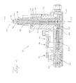
- Figure 2: is a cross-sectional view of the valve assembly employed in Figure 1; and
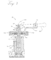
- Figure 3: is a cross-sectional view, generally taken along line 3-3, of the valve assembly seen in Figure 2.
- Referring now to the drawings, a hydro-
mechanical transmission 10 for an agricultural vehicle, such as a tractor is schematically shown in FIG. 1. The hydro-mechanical transmission 10 generally includes an input shaft 12 driven by anengine 14, a hydrostatic unit 16 (having apump 18 and a motor 20) driven by the input shaft 12, amechanical transmission 13 driven by the input shaft 12 (via the engine 14) and thehydrostatic unit 16, avalve assembly 15 controlling the output speed of thehydrostatic unit 16 and the operative gear set of themechanical transmission 13, and a control lever assembly 17 (accessible to the tractor operator) for controlling thevalve assembly 15. - The
hydrostatic unit 16 is a closed hydraulic system including avariable displacement pump 18 driven by the input shaft 12 and a fixeddisplacement motor 20 driving themechanical transmission 13. More specifically, thepump 18 includes aninput shaft 24 rotatably coupled with the engine input shaft 12 by a pair ofgears pump 18 converts the rotational motion of theinput shaft 24 into fluid flow between thepump 18 and themotor 20 viahydraulic lines 22. Thepump 18 is a variable-displacement pump having a variable coupling mechanism, such as a swash plate (not shown), that is controlled by thevalve assembly 15. Accordingly, thevalve assembly 15 controls the angle of the swash plate to adjust the fluid flow within thehydrostatic lines 22. Themotor 20 is rotated by the fluid flow within thelines 22 so as to convert the fluid flow into rotational motion of a hydrostaticunit output shaft 28. Therefore, the angle of the swash plate controls the rotational speed of the hydrostaticunit output shaft 28. Those skilled in the art will recognize that either or both of thepump 18 and themotor 20 may be variable displacement components. - The hydrostatic
unit output shaft 28 is coupled with themechanical transmission 13 by adriving gear 29 connected to theoutput shaft 28 and a drivengear 30, as will be discussed in more detail below. - As seen above, the
mechanical transmission 13 is driven by both a hydrostatic power input element and a mechanical power input element in parallel with each other. The mechanical power input element causes the output of themechanical transmission 13 to rotate at a set "base" speed, which depends solely on the operative gear set, while the hydrostatic power input element adjusts the base speed via thehydrostatic unit 16. In this manner, the hydro-mechanical transmission 10 utilizes the efficient nature of themechanical transmission 13 to achieve a base speed and utilizes the infinitely variable nature of thehydrostatic unit 16 to adjust the output speed as desired. - The
mechanical transmission 13 includes aplanetary system 32 having threeplanetary gear sets planet gear carrier 40 that carries the integral planet gears P1 and P2 ofplanetary gear sets gear carrier 40 also carries the planet gears P3 and P4 of the reversingplanetary gear set 38. The planet gears P1 and P2 are integrally formed and thus rotate together. The planet gears P2 mesh with a ring gear R2. - The ring gear R2 is formed integrally with the driven
gear 30, in a position coaxial with the input shaft 12 of theengine 14. As mentioned above, the drivengear 30 is rotated by thedriving gear 29 of thehydrostatic unit 16 so that the ring gear R2 serves as the hydrostatic power input element to themechanical transmission 13. - The transmission input shaft 12 also directly drives a sun gear S1 of the first
planetary gear set 34. Therefore, the sun gear S1 is the mechanical power input element to themechanical transmission 13. The sun gear S1 meshes with the planet gear P1, that are integrally formed with planet gears P2 as mentioned above. The planet gears P2 mesh with a sun gear S2 and both are part of the planetary gear set 36. - Two clutches, a low range clutch CL and a high range clutch CH, selectively couple elements of the
planetary system 32 to the mechanicaltransmission output shaft 46. Theshaft 46 is a sleeve shaft that surrounds the input shaft 12, which extends through the entiremechanical transmission 13 to drive a power take off, not shown, and/or to drive other vehicle components, such as a hydraulic pump, in a known manner for an agricultural tractor. The low range clutch CL is engageable to couple thecarrier 40 to theoutput shaft 46 for a low speed forward range. The high range clutch CH is engageable to couple the sun gear S2 to theoutput shaft 46 for a high speed forward range. - The
output shaft 46 is fixed to a sun gear S3 of the reversing planetary gear set 38. Ring gear R3 is selectively grounded by a reverse clutch in the form of areverse brake 48. This stops the rotation of the ring gear R3 and causes the sun gear S3 to rotate in the reverse direction for a reverse speed range. When thereverse brake 48 is applied, both the low and high range clutches CL and CH are disengaged, whereby the sun gear S3 drives theoutput shaft 46. - The
output shaft 46 of the mechanical transmission is integrally formed with agear 50 that in turn meshes with agear 52 on the offsetshaft 54. The offsetshaft 54 is coupled to thedifferential drive shaft 56 of the tractor to couple the hydro-mechanical transmission 10 to a load. - The hydro-
mechanical transmission 10 thus operates in three ranges, a reverse range, a low speed forward range and a high speed forward range. Each range uses a separate path through the mechanical transmission to theoutput shaft 46 resulting in unique gear ratios for each range. - The
valve assembly 15 and thecontrol lever assembly 17, shown in Figure 1, cooperate to serve two main functions: first, selectively actuating the low range clutch CL, the high range clutch CH, and thereverse brake 48 to shift between operative gear sets; and, second, adjusting the variable-displacement pump 18 to control the hydrostatic power input element tomechanical transmission 13 and control the speed of the tractor. - The
control lever assembly 17, thevalve assembly 15, and each of the respective clutches CL, CH, andreverse brake 48 are connected with each other byphysical working connections 60. As used herein, the term "physical working connections" refers to any type of connection between respective components that utilizes physical forces, such as a mechanical connection, a hydraulic connection, or a pneumatic connection. For example, thephysical working connections 60 shown in the figures include amechanical connection 62 between thecontrol lever assembly 17 and thevalve assembly 15 and ahydraulic connection 64 between the valve assembly and each of the respective clutches CL, CH, and thereverse brake 48. - The
control lever assembly 17 includes acontrol lever 66 that is movable along atrack 68 and that is accessible to the tractor operator. Thecontrol lever 66 extends downward below the exposed surfaces of the tractor and is mechanically connected to thevalve assembly 17 by ashift linkage 70 and apressure linkage 72, as will be discussed further below. - Generally, the
valve assembly 15 is fluidly connected to thepump 18 by a pair ofhydraulic lines 74 so as to define a closed hydraulic system for controlling the position of the swash plate and by another pair ofhydraulic lines 75 so as to define a second closed hydraulic system for adjusting the operative gear set. Also, thevalve assembly 15 is fluidly connected with each of the respective clutches CL, CH, andreverse brake 48 by a plurality ofhydraulic paths hydraulic paths paths - Referring to Figure 2, the
valve assembly 15 is shown in more detail. Particularly, thevalve assembly 15 has ahousing 82 supporting a shiftcontrol valve assembly 84 for shifting the operative gear set and a pressurecontrol valve assembly 86 for controlling the hydrostatic power input element tomechanical transmission 13. Thehousing 82 also supports a lowgear actuating valve 88 for engaging the low clutch CL, a highgear actuating valve 90 for engaging the high clutch CH, and a reversegear actuating valve 92 for engaging thereverse brake 48. Moreover, the housing defines: the lowhydraulic path 76, which extends between the shiftcontrol valve assembly 84 and the lowgear actuating valve 88; the highhydraulic path 78, which extends between the shiftcontrol valve assembly 84 and the highgear actuating valve 90; and the reversehydraulic path 80, which extends between the shiftcontrol valve assembly 84 and the reversegear actuating valve 92. Although therespective paths housing 82, each pathway having an appropriate size and shape for receiving a working fluid. - Generally, the shift
control valve assembly 84 includes aninner valve 94 positioned within ashift cavity 96 of thehousing 82. The pressurecontrol valve assembly 86 includes anouter valve 98 coaxially positioned around theinner valve 94 within the shift cavity and apressure control valve 100 engaging abase portion 102 of theouter valve 98 and extending generally perpendicularly away therefrom. Each of thevalves housing 82. Namely, theinner valve 94 is movable with respect to theouter valve 98 along a centrallongitudinal axis 104 of the inner andouter valves longitudinal axis 104 within theshift cavity 96; and thepressure control valve 100 is movable with respect to thehousing 82 along atransverse axis 106 that is generally perpendicular tolongitudinal axis 104. - The
inner valve 94 is mechanically connected to the control lever 66 (seen in Figure 1 and shown in phantom in Figure 3) by theshift linkage 70. Theshift linkage 70 shown in the figures is a bore extending through a top portion of theinner valve 94 for receiving an engagement pin of thecontrol lever 66, but any other appropriate connection may be used. For example, one or more connection arms and other linkages may be utilized to mechanically link thecontrol lever 66 to theinner valve 94. Theinner valve 94 is releaseably secured in one of four positions by a pair of support pins 108 that extend through theouter valve 98 and engage agroove 110 formed in the surface of theinner valve 94. The support pins 108 are both biased inward towards theinner valve 94 by respective springs 112 so that theinner valve 94 is held in place within theouter valve 98, unless a sufficiently strong force acts on theinner valve 94 via theshift linkage 70. - As mentioned above, the inner valve has four positions, each corresponding to an operative gear set 32, 34, 36. For example, the position shown in Figures 2 and 3 is a first position, where the support pins 108 are aligned with the
top groove 110 and theinner valve 94 is in its lowermost position within theouter valve 98, such that the reverse gear set 38 is engaged. As theinner valve 94 is moved upwards into each of the remaining three positions, themechanical transmission 13 will progressively engage the low gear set 34, the high gear set 36, and a neutral position where none of the gear sets 34, 36, 38 are engaged. - As mentioned above, the
housing 82 defines a plurality ofhydraulic paths shift cavity 96 and therespective actuating valves inner valve 94 moves between the four positions, each of therespective actuating valves shift cavity 96, thereby selectively actuating one of thevalves reverse brake 48. More specifically, theinner valve 94 defines abore 114 extending therethrough and thehousing 82 defines a passageway 116 extending between thepump 18 and theshift cavity 96. Furthermore, the respectivehydraulic paths shift cavity 96 at different positions along the verticallongitudinal axis 104 so that thebore 114 is only aligned with one of the respectivehydraulic paths outer valve 98 also includes bores (not shown) extending through the outer valve wall andgrooves 118 aligned with each of the bores and extending annularly around theouter valve 98 so that fluid can flow through theouter valve 98. Thepump 18 is fluidly connected with theshift cavity 96 byhydraulic lines 75 so that thepump 18 and the shiftcontrol valve assembly 84 cooperate to define a closed hydraulic system. - During operation, as the
inner valve 94 moves between the respective four positions, the respectivehydraulic paths shift cavity 96 and thepump 18 via thebore 114 in theinner valve 94. Thevalve assembly 15 also includes a purge conduit 122 (Figure 3) connected to theshift cavity 96 so that the working fluid is drained from a given hydraulic path and the respective actuating valve is disengaged when theinner valve 94 moves out of a particular position. Therefore, only oneactuating valve - As mentioned above, the pressure
control valve assembly 86 includes theouter valve 98 coaxially positioned around theinner valve 94 and thepressure control valve 100 that engages thebase portion 102 of theouter valve 98. Theouter valve 98 is connected to the control lever 66 (seen in Figure 1 and shown in phantom in Figure 3) by theshift linkage 72. Theshift linkage 72 shown in Figure 3 is aradial arm 124 extending away from theouter valve 98 and includes a bore extending through a portion of the arm for receiving an engagement pin of thecontrol lever 66. - While specifically shown, any other appropriate connection may be used. For example, one or more connection arms and linkages may be utilized to mechanically link the
control lever 66 to theouter valve 98. - The
outer valve 98 is free to rotate within thehousing 82 when a sufficiently strong rotational force is applied to theradial arm 124. As mentioned above, thebase portion 102 of theouter valve 98 includes a varyingradius 125. Therefore, as theouter valve 98 is rotated, the pressurecontrol valve spring 127 is caused to compress or relax. The spring force is countered by the pressure in thepressure control cavity 126 of thepressure control valve 100. As the spring force is adjusted, the control pressure in thecavity 126 is adjusted and the working fluid flows towards or away from thepump 18 via thehydraulic lines 74, thereby adjusting the angular position of the swash plate in thepump 18 and adjusting the hydrostatic power input element acting on themechanical transmission 13. - Referring back to Figure 1, during operation of the tractor, the
control lever 66 is movable along thetrack 68 to follow a generally step-shaped path. More specifically, thetrack 68 includes: areverse portion 130 controlling the speed of the tractor when the reverse gear set 38 is engaged, a low gear portion 132 controlling the speed of the tractor when the low gear set 36 is engaged, a high gear portion 134 controlling the speed of the tractor when the high gear set 34 is engaged, afirst shifting portion 136 for shifting between the reverse and the low gear sets, and asecond shifting portion 138 for shifting between the low gear and the high gear sets. The reverse, low, andhigh gear portions 130, 132, 134 of thetrack 68 are each generally parallel with each other so that movement of thecontrol lever 66 along afirst axis 140 actuates thepressure linkage 72 and rotates theouter valve 98, thereby adjusting the hydrostatic power input element acting on themechanical transmission 13. Similarly, the first and second shiftingportions control lever 66 along asecond axis 142 actuates theshift linkage 70 and vertically moves theinner valve 94, thereby shifting the operative gear set 34, 36, 38. Therefore, the operator is able to operate the tractor in a relatively simple, convenient manner. - It is therefore intended that the foregoing detailed description be regarded as illustrative rather than limiting, and that it be understood that it is the following claims, including all equivalents, that are intended to define the spirit and scope of this invention. For example, the hydrostatic pump and motor may be replaced with a variable speed friction drive that is controlled hydraulically.
Claims (21)
- A hydro-mechanical transmission (10) comprising an input shaft (12) configured to be rotated by a power source (14); a hydrostatic unit (16) coupled with the input shaft (12) and having a driving component (29); a mechanical transmission (13) having a driven component (30) coupled with the driving component (29) of the hydrostatic unit (16), an output shaft (46) configured to drive a load, a first gear set (34, 36, 38) selectively coupling the driven component (30) with the output shaft (46) when a first clutch (48, CL, CH) is engaged, and a second gear set (34, 36, 38) selectively coupling the driven component (30) with the output shaft (46) when a second clutch (48, CL, CH) is engaged, characterized in comprising a valve assembly (15) coupled with the hydrostatic unit (16) and the mechanical transmission (13), wherein the valve assembly having a pressure control valve assembly (86) coupled with the hydrostatic unit (16) to control an output speed of the driving component (29) and a shift control valve assembly (84) coupled with the mechanical transmission (13) to selectively engage at least one of the first and second clutches (48, CL, CH).
- A hydro-mechanical transmission (10) as in claim 1, comprising a movable control lever (66) coupled with the valve assembly (15) so that the control lever (66), the shift control valve assembly (84), and the at least one of the first and second clutches (48, CH, CL) are connected with each other by physical working connections.
- A hydro-mechanical transmission (10) as in claim 2, wherein the physical working connections include a mechanical connection (62) between the control lever (66) and the shift control valve assembly (84).
- A hydro-mechanical transmission (10) as in claim 3, wherein the shift control valve assembly (84) includes a shift control valve (94) movable between a first position where the first clutch (48, CL, CH) is engaged, and a second position where the second clutch (48, CL, CH) is engaged, and wherein the mechanical connection (62) between the control lever (66) and the shift control valve assembly (84) connects the control lever (66) and the shift control valve (94) such that movement of the control lever (66) along a shift path (68) causes movement of the shift control valve (94) between the first and second positions.
- A hydro-mechanical transmission (10) as in one of the claims 2 to 4, wherein the physical working connections further include a hydraulic connection (64) between the shift control valve (94) and the at least one of the first and second clutches (48, CL, CH).
- A hydro-mechanical transmission (10) as in claim 5, wherein the hydraulic connection (64) between the shift control valve (94) and the at least one of the first and second clutches (48, CL, CH) includes: a first actuating valve (88, 90, 92) positioned adjacent to the first clutch (48, CL, CH) and configured to be moveable between a retracted position and an extended position to engage the first clutch (48, CL, CH); a first hydraulic path (76, 78, 80) formed in a housing (82) of the valve assembly (15) and fluidly connecting the shift control valve (94) and the first actuating valve (88, 90, 92) so the first actuating valve (88, 90, 92) is in the extended position and the first clutch (48, CL, CH) is engaged when the shift control valve (94) is in the first position; a second actuating valve (88, 90, 92) positioned adjacent to the second clutch (48, CL, CH) and configured to be moveable between a retracted position and an extended position to engage the second clutch (48, CL, CH); and a second hydraulic path (76, 78, 80) formed in the housing (82) of the valve assembly (15) and fluidly connecting the shift control valve (94) and the second actuating valve (88, 90, 92) so the second actuating valve (88, 90, 92) is in the extended position and the second clutch (48, CL, CH) is engaged when the shift control valve (94) is in the second position.
- A hydro-mechanical transmission (10) as in one of the claims 1 to 6, wherein the mechanical transmission (13) further including a reverse gear set (38) selectively coupling the driven component (30) with the output shaft (46) when a reverse clutch (48) is engaged.
- A hydro-mechanical transmission (10) as in one of the claims 1 to 7, wherein the valve assembly (15) further including: a housing (82) defining a shift cavity (96); a first actuating valve (88, 90, 92) supported by the housing (82) and configured to selectively engage the first clutch (48, CH, CL); a second actuating valve (88, 90, 92) supported by the housing (82) configured to selectively engage the second clutch (48, CH, CL); a shift control valve (94) movable within the shift cavity (96) between a first position where the shift cavity (96) is fluidly connected with the first actuating valve (88, 90, 92) and the first clutch (48, CH, CL) is engaged, and a second position where the shift cavity (96) is fluidly connected with the second actuating valve (88, 90, 92) and the second clutch (48, CH, CL) is engaged; and a pressure control valve assembly (86) coupled with the hydrostatic unit (16) to control an output speed of the driving component (29).
- A hydro-mechanical transmission (10) as in one of the claims 2 to 8, further comprising a movable control lever (66) coupled with the shift control valve (94) and the pressure control valve assembly (86) so that movement of the control lever (66) along a first axis moves the shift control valve (94) and so that movement of the control lever (66) along a second axis moves the pressure control valve assembly (86).
- A hydro-mechanical transmission (10) as in claim 8 or 9, wherein the shift cavity (96) is fluidly connected with the hydrostatic unit (16) and wherein the shift control valve (94) permits delivery of a working fluid from the hydrostatic unit (16) to the first actuating valve (88, 90, 92) when the shift control valve (94) is in the first position and permits delivery of the working fluid from the hydrostatic unit (16) to the second actuating valve (88, 90, 92) when the shift control valve (94) is in the second position.
- A hydro-mechanical transmission (10) as in one of the claims 8 to 10, wherein the shift control valve (94) includes a wall defining an opening (114) extending through the wall and wherein the opening (114) fluidly connects the shift cavity (96) to the first actuating valve (88, 90, 92) when the shift control valve (94) is in the first position and the opening (114) fluidly connects the shift cavity (96) to the second actuating valve (88, 90, 92) when the shift control valve (94) is in the second position.
- A hydro-mechanical transmission (10) as in one of the claims 1 to 11, the hydrostatic unit (16) further including a pump (18) driven by the input shaft (12) and a motor (20) rotatably driving the driving component (29), and a variable coupling mechanism coupling the pump (18) and the motor (20) with each other, wherein the pressure control valve assembly (86) is fluidly connected with the variable coupling mechanism to control an output speed of the driving component (29) with respect to an input speed of the input shaft (12).
- A hydro-mechanical transmission (10) as in claim 12, wherein the pressure control valve assembly (86) includes a pressure control valve (100) fluidly connected with the variable coupling mechanism of the hydrostatic unit (16) to control the rotation speed of the driving component (29) and an outer valve (98) coaxially positioned around the shift control valve (94) and configured to control the position of the pressure control valve (100).
- A hydro-mechanical transmission (10) as in claim 13, wherein the outer valve (98) includes a base portion (102) defining a varying radius and engaging the pressure control valve (100) so that rotation of the outer valve (98) controls the position of the pressure control valve (100) and therefore the pressure.
- A hydro-mechanical transmission (10) as in one of the claims 8 to 14, wherein the pressure control valve assembly (86) having an outer valve (98) positioned within the shift cavity (96) so as to be generally coaxial with the shift control valve (94), wherein the pressure control valve assembly (86) is coupled with the hydrostatic unit (16) to control an output speed of the driving component (29).
- A hydro-mechanical transmission (10) as in one of the claims 8 to 15, further comprising a movable control lever (66) coupled with the shift control valve (94) and the pressure control valve assembly (86) so that movement of the control lever (66) along a first axis moves the shift control valve (94) and so that movement of the control lever (66) along a second axis moves the pressure control valve assembly (86).
- A hydro-mechanical transmission (10) as in one of the claims 13 to 16, wherein the outer valve (98) includes a base (102) portion defining a varying radius and engaging the pressure control valve (100) so that rotation of the outer valve (98) controls the position of the pressure control valve (100).
- A valve assembly (15) for a hydro-mechanical transmission (10), the valve assembly (15) comprising: a housing (82) at least partially defining a valve support cavity (96), a first fluid path (76, 78, 80), and a second fluid path (76, 78, 80), and a pressure control cavity; first and second actuating valves (88, 90, 92) supported by the housing (82); a first control valve (94) movable within the valve support cavity (96) between a first position, where the valve support cavity (96) is fluidly connected with the first actuating valve (88, 90, 92), and a second position, where the valve support cavity (96) is fluidly connected with the second actuating valve (88, 90, 92); and a second control valve (98) movable within the valve support cavity (96) between a first position, where the pressure control cavity has a first volume, and a second position, where the pressure control cavity has a second volume.
- A valve assembly (15) as in claim 18, wherein the first control valve (94) is able to translate within the valve support cavity (96) between the first and second positions of the first control valve (94) and wherein the second control valve (98) is able to rotate within the valve support cavity (96) between the first and second positions of the second control valve (98).
- A valve assembly (15) as in claim 18 or 19, further comprising a pressure control valve (100) cooperating with the housing (82) to define the pressure control cavity, wherein the pressure control valve (100) is coupled with the second control valve (98) so that the rotation of the second control valve (98) controls the pressure of the pressure control valve (100).
- A valve assembly (15) as in one of the claims 18 to 20, wherein the second control valve (98) includes a base portion (102) defining a varying radius and engaging the pressure control valve (100) so that rotation of the second control valve (98) controls the position of the pressure control valve (100).
Applications Claiming Priority (1)
| Application Number | Priority Date | Filing Date | Title |
|---|---|---|---|
| US11/488,260 US7588510B2 (en) | 2006-07-18 | 2006-07-18 | Hydro-mechanical transmission and valve assembly |
Publications (3)
| Publication Number | Publication Date |
|---|---|
| EP1881242A2 true EP1881242A2 (en) | 2008-01-23 |
| EP1881242A3 EP1881242A3 (en) | 2011-03-02 |
| EP1881242B1 EP1881242B1 (en) | 2012-04-04 |
Family
ID=38596066
Family Applications (1)
| Application Number | Title | Priority Date | Filing Date |
|---|---|---|---|
| EP20070112720 Active EP1881242B1 (en) | 2006-07-18 | 2007-07-18 | Hydro-mechanical transmission and valve assembly |
Country Status (3)
| Country | Link |
|---|---|
| US (2) | US7588510B2 (en) |
| EP (1) | EP1881242B1 (en) |
| BR (1) | BRPI0703037A (en) |
Families Citing this family (5)
| Publication number | Priority date | Publication date | Assignee | Title |
|---|---|---|---|---|
| US7588510B2 (en) * | 2006-07-18 | 2009-09-15 | Deere & Company | Hydro-mechanical transmission and valve assembly |
| RU2398992C1 (en) * | 2006-08-03 | 2010-09-10 | Тойота Дзидося Кабусики Кайся | Automotive transmission |
| DE102008021010B4 (en) * | 2008-04-25 | 2010-02-25 | Lohmann & Stolterfoht Gmbh | Power split transmission |
| US8839694B2 (en) * | 2009-06-05 | 2014-09-23 | Deere & Company | Hydraulic regenerating and low-speed operating power shift transmission |
| US9958061B2 (en) | 2016-04-25 | 2018-05-01 | Caterpillar Inc. | Method for controlling variator of transmission system |
Citations (1)
| Publication number | Priority date | Publication date | Assignee | Title |
|---|---|---|---|---|
| US20050071068A1 (en) | 2003-09-26 | 2005-03-31 | Komatsu Ltd. | Vehicle control system |
Family Cites Families (15)
| Publication number | Priority date | Publication date | Assignee | Title |
|---|---|---|---|---|
| US2494183A (en) * | 1946-07-06 | 1950-01-10 | John W Lincoln | Control system for hydraulically actuated valves and the like |
| US2700985A (en) * | 1954-02-08 | 1955-02-01 | Vernon E Gleasman | Rotary control valve |
| US2879801A (en) * | 1954-08-17 | 1959-03-31 | Richard T Cornelius | Beverage mixing and dispensing devices |
| US3204486A (en) * | 1963-03-06 | 1965-09-07 | Lalio George M De | Infinitely variable power transmission |
| US3455184A (en) * | 1967-12-27 | 1969-07-15 | Sundstrand Corp | Transmission |
| US3602243A (en) * | 1969-07-07 | 1971-08-31 | Eaton Yale & Towne | Pressure compensated multifunction control valve |
| DE2237595B1 (en) * | 1972-07-31 | 1973-10-25 | Hydromatik Gmbh, 7900 Ulm | TRANSMISSION ADJUSTMENT FOR A COMPOSITE TRANSMISSION CONSISTING OF AN ADJUSTABLE HYDROSTATIC GEAR UNIT AND A SUBSEQUENT MECHANICAL POWER SHIFT TRANSMISSION |
| US3823801A (en) * | 1973-09-07 | 1974-07-16 | Twin Disc Inc | Clutches with a fluid and cam operated pressure modulating valve |
| US4024775A (en) * | 1975-07-09 | 1977-05-24 | Caterpillar Tractor Co. | Hydrostatic mechanical transmission and controls therefor |
| US4469007A (en) * | 1981-11-20 | 1984-09-04 | Caterpillar Tractor Co. | Single lever control with automatic valve latching |
| US4545402A (en) * | 1984-04-12 | 1985-10-08 | American Standard Inc. | Pressure-regulating valve with a force-feedback |
| US5683322A (en) * | 1993-04-21 | 1997-11-04 | Meyerle; Michael | Continuous hydrostatic-mechanical branch power split transmission particularly for power vehicles |
| JP2600061B2 (en) * | 1993-07-14 | 1997-04-16 | 株式会社小松製作所 | Tracked vehicle steering system |
| US6729454B2 (en) * | 2002-05-06 | 2004-05-04 | Deere & Company | Transmission with a two-step actuator valve |
| US7588510B2 (en) * | 2006-07-18 | 2009-09-15 | Deere & Company | Hydro-mechanical transmission and valve assembly |
-
2006
- 2006-07-18 US US11/488,260 patent/US7588510B2/en active Active
-
2007
- 2007-07-17 BR BRPI0703037-1A patent/BRPI0703037A/en not_active Application Discontinuation
- 2007-07-18 EP EP20070112720 patent/EP1881242B1/en active Active
-
2009
- 2009-08-11 US US12/538,912 patent/US8522822B2/en active Active
Patent Citations (1)
| Publication number | Priority date | Publication date | Assignee | Title |
|---|---|---|---|---|
| US20050071068A1 (en) | 2003-09-26 | 2005-03-31 | Komatsu Ltd. | Vehicle control system |
Also Published As
| Publication number | Publication date |
|---|---|
| US20080020894A1 (en) | 2008-01-24 |
| EP1881242A3 (en) | 2011-03-02 |
| BRPI0703037A (en) | 2008-03-04 |
| EP1881242B1 (en) | 2012-04-04 |
| US8522822B2 (en) | 2013-09-03 |
| US7588510B2 (en) | 2009-09-15 |
| US20100287925A1 (en) | 2010-11-18 |
Similar Documents
| Publication | Publication Date | Title |
|---|---|---|
| EP2125419B1 (en) | Hydraulic actuation valve arrangement for dual clutch transmission | |
| JP2852714B2 (en) | Fluid pressure transmitter | |
| US8172714B2 (en) | Speed changing transmission apparatus | |
| US6361463B1 (en) | Drive transmission for vehicles | |
| US3714846A (en) | Hydrostatic-differential transmission | |
| JP4740174B2 (en) | Variable speed transmission | |
| US8522822B2 (en) | Hydro-mechanical transmission and valve assembly | |
| CN101589247A (en) | Drive mechanism for infinitely variable transmission | |
| US8920277B2 (en) | Hydromechanical transmission with a hydraulic motor and a mechanical multi-step variable speed transmission | |
| US20150292617A1 (en) | Control mechanism for a continuously variable transmission | |
| DK2860426T3 (en) | Hydromechanical transmission | |
| KR101017785B1 (en) | Gearbox | |
| US5239897A (en) | Automatic selector device for a multi-gear change-speed gearbox | |
| US9975424B2 (en) | Dropbox assembly for transmission of work vehicle | |
| JP2722036B2 (en) | Automatic gear selector for multi-gear transmissions | |
| US4024775A (en) | Hydrostatic mechanical transmission and controls therefor | |
| CN115638223A (en) | Transmission structure | |
| RU2399817C2 (en) | Stepless transmission | |
| USRE30525E (en) | Extended range hydraulic transmission | |
| JP4392185B2 (en) | Power transmission device for tractor | |
| KR101326416B1 (en) | Transmission of vehicle | |
| JP5065810B2 (en) | Variable speed transmission | |
| US11796041B2 (en) | Planetary gear assembly, power-split stepless transmission, and transmission structure | |
| KR101326351B1 (en) | Transmission of vehicle | |
| JP4891867B2 (en) | Variable speed transmission |
Legal Events
| Date | Code | Title | Description |
|---|---|---|---|
| PUAI | Public reference made under article 153(3) epc to a published international application that has entered the european phase |
Free format text: ORIGINAL CODE: 0009012 |
|
| AK | Designated contracting states |
Kind code of ref document: A2 Designated state(s): AT BE BG CH CY CZ DE DK EE ES FI FR GB GR HU IE IS IT LI LT LU LV MC MT NL PL PT RO SE SI SK TR |
|
| AX | Request for extension of the european patent |
Extension state: AL BA HR MK YU |
|
| RIC1 | Information provided on ipc code assigned before grant |
Ipc: F16H 61/02 20060101ALI20100609BHEP Ipc: F16H 61/47 20100101AFI20100609BHEP Ipc: F16H 61/437 20100101ALI20100609BHEP |
|
| PUAL | Search report despatched |
Free format text: ORIGINAL CODE: 0009013 |
|
| AK | Designated contracting states |
Kind code of ref document: A3 Designated state(s): AT BE BG CH CY CZ DE DK EE ES FI FR GB GR HU IE IS IT LI LT LU LV MC MT NL PL PT RO SE SI SK TR |
|
| AX | Request for extension of the european patent |
Extension state: AL BA HR MK RS |
|
| 17P | Request for examination filed |
Effective date: 20110902 |
|
| GRAP | Despatch of communication of intention to grant a patent |
Free format text: ORIGINAL CODE: EPIDOSNIGR1 |
|
| AKX | Designation fees paid |
Designated state(s): DE FR GB |
|
| GRAS | Grant fee paid |
Free format text: ORIGINAL CODE: EPIDOSNIGR3 |
|
| GRAA | (expected) grant |
Free format text: ORIGINAL CODE: 0009210 |
|
| AK | Designated contracting states |
Kind code of ref document: B1 Designated state(s): DE FR GB |
|
| REG | Reference to a national code |
Ref country code: GB Ref legal event code: FG4D |
|
| REG | Reference to a national code |
Ref country code: DE Ref legal event code: R096 Ref document number: 602007021717 Country of ref document: DE Effective date: 20120531 |
|
| PLBE | No opposition filed within time limit |
Free format text: ORIGINAL CODE: 0009261 |
|
| STAA | Information on the status of an ep patent application or granted ep patent |
Free format text: STATUS: NO OPPOSITION FILED WITHIN TIME LIMIT |
|
| 26N | No opposition filed |
Effective date: 20130107 |
|
| REG | Reference to a national code |
Ref country code: DE Ref legal event code: R097 Ref document number: 602007021717 Country of ref document: DE Effective date: 20130107 |
|
| PGFP | Annual fee paid to national office [announced via postgrant information from national office to epo] |
Ref country code: FR Payment date: 20140717 Year of fee payment: 8 Ref country code: GB Payment date: 20140729 Year of fee payment: 8 |
|
| GBPC | Gb: european patent ceased through non-payment of renewal fee |
Effective date: 20150718 |
|
| PG25 | Lapsed in a contracting state [announced via postgrant information from national office to epo] |
Ref country code: GB Free format text: LAPSE BECAUSE OF NON-PAYMENT OF DUE FEES Effective date: 20150718 |
|
| REG | Reference to a national code |
Ref country code: FR Ref legal event code: ST Effective date: 20160331 |
|
| PG25 | Lapsed in a contracting state [announced via postgrant information from national office to epo] |
Ref country code: FR Free format text: LAPSE BECAUSE OF NON-PAYMENT OF DUE FEES Effective date: 20150731 |
|
| PGFP | Annual fee paid to national office [announced via postgrant information from national office to epo] |
Ref country code: DE Payment date: 20250620 Year of fee payment: 19 |