EP1881237A1 - System for eliminating backlash - Google Patents
System for eliminating backlash Download PDFInfo
- Publication number
- EP1881237A1 EP1881237A1 EP07075532A EP07075532A EP1881237A1 EP 1881237 A1 EP1881237 A1 EP 1881237A1 EP 07075532 A EP07075532 A EP 07075532A EP 07075532 A EP07075532 A EP 07075532A EP 1881237 A1 EP1881237 A1 EP 1881237A1
- Authority
- EP
- European Patent Office
- Prior art keywords
- biasing members
- members
- biasing
- force
- operational
- Prior art date
- Legal status (The legal status is an assumption and is not a legal conclusion. Google has not performed a legal analysis and makes no representation as to the accuracy of the status listed.)
- Granted
Links
- 230000033001 locomotion Effects 0.000 claims description 25
- 238000000034 method Methods 0.000 claims description 17
- 238000004891 communication Methods 0.000 claims description 14
- 230000004044 response Effects 0.000 claims description 13
- 230000036316 preload Effects 0.000 claims description 12
- 230000008859 change Effects 0.000 claims description 8
- 230000008878 coupling Effects 0.000 claims description 4
- 238000010168 coupling process Methods 0.000 claims description 4
- 238000005859 coupling reaction Methods 0.000 claims description 4
- 230000005540 biological transmission Effects 0.000 claims description 2
- 238000013016 damping Methods 0.000 claims description 2
- 238000010586 diagram Methods 0.000 description 11
- 238000006073 displacement reaction Methods 0.000 description 4
- 230000001627 detrimental effect Effects 0.000 description 3
- 230000000694 effects Effects 0.000 description 3
- 239000000463 material Substances 0.000 description 3
- 230000009467 reduction Effects 0.000 description 3
- 238000013461 design Methods 0.000 description 2
- 230000008030 elimination Effects 0.000 description 2
- 238000003379 elimination reaction Methods 0.000 description 2
- 230000003993 interaction Effects 0.000 description 2
- 229910000639 Spring steel Inorganic materials 0.000 description 1
- 230000009471 action Effects 0.000 description 1
- 230000000712 assembly Effects 0.000 description 1
- 238000000429 assembly Methods 0.000 description 1
- 230000015556 catabolic process Effects 0.000 description 1
- 230000006835 compression Effects 0.000 description 1
- 238000007906 compression Methods 0.000 description 1
- 238000010276 construction Methods 0.000 description 1
- 230000008602 contraction Effects 0.000 description 1
- 238000006731 degradation reaction Methods 0.000 description 1
- 230000026058 directional locomotion Effects 0.000 description 1
- 238000010348 incorporation Methods 0.000 description 1
- 230000013011 mating Effects 0.000 description 1
- 239000007769 metal material Substances 0.000 description 1
- 238000012986 modification Methods 0.000 description 1
- 230000004048 modification Effects 0.000 description 1
- 239000002861 polymer material Substances 0.000 description 1
- 238000000926 separation method Methods 0.000 description 1
- 230000007704 transition Effects 0.000 description 1
Images


Classifications
-
- F—MECHANICAL ENGINEERING; LIGHTING; HEATING; WEAPONS; BLASTING
- F16—ENGINEERING ELEMENTS AND UNITS; GENERAL MEASURES FOR PRODUCING AND MAINTAINING EFFECTIVE FUNCTIONING OF MACHINES OR INSTALLATIONS; THERMAL INSULATION IN GENERAL
- F16H—GEARING
- F16H55/00—Elements with teeth or friction surfaces for conveying motion; Worms, pulleys or sheaves for gearing mechanisms
- F16H55/02—Toothed members; Worms
- F16H55/22—Toothed members; Worms for transmissions with crossing shafts, especially worms, worm-gears
- F16H55/24—Special devices for taking up backlash
-
- F—MECHANICAL ENGINEERING; LIGHTING; HEATING; WEAPONS; BLASTING
- F16—ENGINEERING ELEMENTS AND UNITS; GENERAL MEASURES FOR PRODUCING AND MAINTAINING EFFECTIVE FUNCTIONING OF MACHINES OR INSTALLATIONS; THERMAL INSULATION IN GENERAL
- F16H—GEARING
- F16H57/00—General details of gearing
- F16H57/12—Arrangements for adjusting or for taking-up backlash not provided for elsewhere
- F16H2057/126—Self-adjusting during operation, e.g. by a spring
-
- Y—GENERAL TAGGING OF NEW TECHNOLOGICAL DEVELOPMENTS; GENERAL TAGGING OF CROSS-SECTIONAL TECHNOLOGIES SPANNING OVER SEVERAL SECTIONS OF THE IPC; TECHNICAL SUBJECTS COVERED BY FORMER USPC CROSS-REFERENCE ART COLLECTIONS [XRACs] AND DIGESTS
- Y10—TECHNICAL SUBJECTS COVERED BY FORMER USPC
- Y10T—TECHNICAL SUBJECTS COVERED BY FORMER US CLASSIFICATION
- Y10T74/00—Machine element or mechanism
- Y10T74/19—Gearing
- Y10T74/19623—Backlash take-up
-
- Y—GENERAL TAGGING OF NEW TECHNOLOGICAL DEVELOPMENTS; GENERAL TAGGING OF CROSS-SECTIONAL TECHNOLOGIES SPANNING OVER SEVERAL SECTIONS OF THE IPC; TECHNICAL SUBJECTS COVERED BY FORMER USPC CROSS-REFERENCE ART COLLECTIONS [XRACs] AND DIGESTS
- Y10—TECHNICAL SUBJECTS COVERED BY FORMER USPC
- Y10T—TECHNICAL SUBJECTS COVERED BY FORMER US CLASSIFICATION
- Y10T74/00—Machine element or mechanism
- Y10T74/19—Gearing
- Y10T74/19633—Yieldability in gear trains
-
- Y—GENERAL TAGGING OF NEW TECHNOLOGICAL DEVELOPMENTS; GENERAL TAGGING OF CROSS-SECTIONAL TECHNOLOGIES SPANNING OVER SEVERAL SECTIONS OF THE IPC; TECHNICAL SUBJECTS COVERED BY FORMER USPC CROSS-REFERENCE ART COLLECTIONS [XRACs] AND DIGESTS
- Y10—TECHNICAL SUBJECTS COVERED BY FORMER USPC
- Y10T—TECHNICAL SUBJECTS COVERED BY FORMER US CLASSIFICATION
- Y10T74/00—Machine element or mechanism
- Y10T74/19—Gearing
- Y10T74/19642—Directly cooperating gears
- Y10T74/19698—Spiral
- Y10T74/19828—Worm
Definitions
- first member 14 in the first position 36, as compared to the first member 14' in the second position 36'.
- geometric requirement that as the first member 14 is moved from the first position 36 to the second position 36' it undergoes movement in both an X and a Y displacement, if the biasing members 22 were rigid, according to a Cartesian coordinate system 40, as depicted by ⁇ x and ⁇ y.
- This geometric relationship will be utilized to control operational contact forces and a positional relationship of the first member 14 with respect to a second member 44 as will be described in more detail below.
- the first member 14 is in operable communication with the second member 44.
- the first member represented here as a worm with a shaft 16
- the second member 44 represented here as a worm gear with a shaft 19, is rotationally attached to a bearing 20 that is fixed to the housing 18.
- the members 14 and 44 presented here are gears, they could also be cams or other operationally communicable members.
- the operational communication of the first member 14 and the second member 44 is by way of meshing of gear teeth as will be described in detail with reference to Figures 5 and 6.
- the positional relationship of the members 14 and 44 and the meshing engagement of their teeth is such that the rotation of either member 14 or 44 is necessarily accompanied by rotation of the other member.
- the third biasing members 56 are not rigid but are in fact flexible.
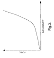
- the flexibility of the third biasing members 56 is controlled by the nonlinear spring constant referred to in FIG 3.
- the flexibility of the third biasing members 56 actually allows the first member 14 to move in a plus Y direction instead of a minus Y direction, thus allowing a single flank contact to occur as shown in FIG. 5.
- This movement of the first member 14 in a plus Y direction results in an elongation of the biasing members 56 and a corresponding increase in the force in the minus Y direction created by the biasing members 56.
- This force in a minus Y direction will also be referred to as a mesh engaging force.
- the mesh engaging force increase, in the minus Y direction resists a further decrease in meshing engagement that if allowed could be detrimental to efficiency.
- this force loop can be tailored for particular applications by adjusting the lengths of the biasing members 56, the force versus deflection curves of the biasing members 56 and the angles of contacting surfaces of the operably communicating members 14, 44, for example.
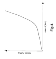
- a graph of an exemplary force loop is depicted with radial force on the vertical axis and axial force on the horizontal axis. This curve is nonlinear with the radial force increasing at a faster rate than the axial force.
- Diagram 60 depicts a partial meshing of a tooth 64 from the first member 14 with teeth 66 of the second member 44.
- the meshing teeth 64 and 66 are shown in single flank contact, such that a first flank 72 of the tooth 64 is in contact with a first flank 82 of the teeth 66, while a second flank 74 of the tooth 64 is not in contact with a second flank 84 of the teeth 66.
- Such single flank contact may result when operational contact forces between the meshing gear teeth 64, 66 force the first member 14 away from the second member 44. More specifically, the contact force causes the first member 14 to ramp up surface 83 of the first flank 82.
- a movement of the first member 14 in an X direction must also include an incremental force increase in the minus Y direction.
- the incremental force increase in the minus Y direction counters the separation forces between the first member 14 and the second member 44 thereby maintaining the members 14, 44 in a preferred meshing position. Therefore, the forgoing structure maintains a desirable positional relationship between the first member 14 and the second member 44 throughout various operational parameters of the first member 14 with the second member 44.
- a schematic 110 of an embodiment of the invention, incorporating a preload to address a source of impact noise, is depicted.
- the urging force forms a preload generated by the third biasing members 56, incorporated into first biasing members 52, which connect the first member 14 to the housing 18 through bearings 48.
- the preload force of third biasing members 56 is set to maintain tooth 64 to teeth 66 contact at all times, and specifically during times of directional changes of the members 14, 44 and of vibration of the full assembly.
- the single flank contact between flanks 72, of the tooth 64, and flank 82, of the teeth 66 (FIG. 5) needs to be maintained until the double flank contact of FIG. 6 is established. Stated another way; impact noise may be minimized or prevented during transition from a single flank contact in one direction to a single flank contact in the opposite direction, by transitioning through a momentary double flank contact and minimizing the contact force at that instant.
- the schematic 120 of FIG. 7 incorporates first biasing members 122 to connect the first member 14 to the housing 18 through the bearings 48.
- the biasing members 122 are formed with a curved or bowed shape and are made of a flexible material with memory, such as spring steel for example, to form a flexible shaped member.
- the flexible shaped member creates a force that resists any straightening action to remove the bowed shape.
- the bowed shape can be formed to create a biasing force, on the first member 14, in the minus Y direction per the Cartesian coordinate system 40, thereby acting to pull the first member 14 towards the second member 44.
- FIG. 9 Another embodiment of the invention, shown in schematic 150 of FIG. 9, has third biasing members 156 connected to first biasing members 152.
- a first end 151 of the third biasing members 156 connect to the biasing members 152 in a similar manner as to how the third biasing members 136 attach to the biasing members 132 of FIG. 8.
- Second ends 159 of the third biasing members 156 are connected to the housing 18.
- the first biasing members 152 are each made from a first submember 157 and a second submember 158. Both of the submembers 157 and 158 are rigid and can articulate about their ends.
Landscapes
- Engineering & Computer Science (AREA)
- General Engineering & Computer Science (AREA)
- Mechanical Engineering (AREA)
- Gear Transmission (AREA)
- Power Steering Mechanism (AREA)
- Transmission Devices (AREA)
- Gears, Cams (AREA)
- Paper (AREA)
- Devices For Conveying Motion By Means Of Endless Flexible Members (AREA)
- Medicines Containing Antibodies Or Antigens For Use As Internal Diagnostic Agents (AREA)
Abstract
Description
- Backlash is a major source of undesirable noise in gear assemblies. Backlash allows the teeth of one gear to, momentarily, lose contact with the teeth of the mating gear. The noise is generated, by a tooth-to-tooth impact that occurs, when the teeth of the two gears reestablish contact with one another. The momentary loss of contact between meshing teeth often happens during specific operating conditions of the gear assembly. Such conditions include; during excessive vibration and during directional changes of at least one of the gears, for example.
- Typical gear assembly design practices rely upon geometric tolerancing to position meshed gears in operable relation to one another. However, due to variation in build tolerances and component wear, clearances have to exist between the teeth of meshed gears, thereby allowing backlash, and the undesirable noise associated with it to persist.
- In addition to noise, clearances may also cause degradation in operational efficiency of the meshed gears due to the contact point between the gear teeth deviating from the preferred design location. The contact force between the meshed gears is one major cause of this deviation. The contact force includes a radial component that acts in a direction to separate the gears from one another. Consequently, any clearances in the meshed gears may be biased to increase the distance between the axes of the gears resulting in reduced meshing engagement. The reduced meshing engagement alters the contact point between the meshed gears, which may result in a loss of efficiency and strength.
- Typical methods employed to minimize these clearances include both springs and dampers. The springs are used to bias the gears toward one another in an attempt to assure that the gears are fully meshed together regardless of the clearances. However, the spring forces necessary to maintain the gears in full meshed engagement cause a loss in efficiency due to an increase in friction between the meshed gear teeth. Dampers are employed to allow for use of springs with lesser biasing forces. Such lighter force springs create a preload when the gears are not operationally engaged. A high damper stiffness is used to counter the separational forces of the meshed gears and to thereby reduce the backlash and loss of efficiency that results from the gears moving away from one another.
- During operation, the load put on the dampers varies significantly as the operational conditions of the meshing gears change. For the dampers to successfully counter these varying forces the damper coefficients of the dampers must vary depending on the operating conditions of the gear assembly. It may be possible to create variable dampers, and algorithms to control them, based upon the operational conditions of the meshed gears. However, such systems may be highly complex, costly, and still have negative effects on the operational efficiency of the assembly.
- Accordingly, there is a need in the art for a concept that automatically eliminates backlash and maintains a desired positional relationship of the meshing gears regardless of the operating conditions of the meshed gears.
- Disclosed herein is a system to control a contact force and a positional relationship between members in operable communication. The system comprising, a first member, a second member in operable communication with the first member, and a contact force and a positional relationship exists between the first member and the second member. The system further comprising first biasing members being configured to bias and position the first member, and the contact force and positional relationship are influenced by a response of the first biasing members to the contact forces between the members in operable communication.
- Further disclosed is a method of controlling the contact force and positional relationship of operably communicating members. The method comprising, operably coupling a first member to a second member with biasing members such that an operational contact force and a positional relationship exists between the first member and the second member, and adjusting the operational position and contact force through response of the coupling of the first member to the second member.
- The following descriptions should not be considered limiting in any way.
- With reference to the accompanying drawings, like elements are numbered alike:
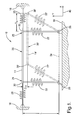
- FIG. 1 depicts a schematic of linked members disclosed herein;
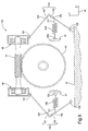
- FIG. 2 depicts a diagram of operably communicating members with a preload biasing member disclosed herein;
- FIG. 3 depicts a graph of force versus displacement for biasing members disclosed herein;
- FIG. 4 depicts a graph of a force loop disclosed herein;
- FIG. 5 depicts a diagram of gear teeth in mesh with single flank contact;
- FIG. 6 depicts a diagram of gear teeth in mesh with double flank contact;
- FIG. 7 depicts a diagram of operably communicating members with bowed biasing members disclosed herein;
- FIG. 8 depicts a diagram of operably communicating members with adjustable biasing members disclosed herein; and
- FIG. 9 depicts a diagram of an alternate embodiment of operably communicating members with adjustable biasing members disclosed herein.
- Referring to FIG. 1, a schematic 10 of a moveable
first member 14 in accordance with an embodiment of the invention is depicted. First biasingmembers 22 attach opposing ends of thefirst member 14 to ahousing 18. Eachfirst biasing member 22 is rotationally attached to thehousing 18, by apivot 26, on one end, and to thefirst member 14, by apivot 30, on the other end. Thepivots first member 14 to move from afirst position 36 to a second position 36'. The first member 14', the biasing members 22', and the pivots 30' are shown by dashed lines in the second position 36'. The structure thus described is similar to a parallelogram formed by a first pair of opposing sides made by biasing members 22' and a second pair of opposing sides made by the first member 14' and adashed line 34 connectingpivots 26. - Of particular interest, in this embodiment, is the relationship of the
first member 14, in thefirst position 36, as compared to the first member 14' in the second position 36'. Specifically, the geometric requirement that as thefirst member 14 is moved from thefirst position 36 to the second position 36' it undergoes movement in both an X and a Y displacement, if thebiasing members 22 were rigid, according to aCartesian coordinate system 40, as depicted by Δx and Δy. This geometric relationship will be utilized to control operational contact forces and a positional relationship of thefirst member 14 with respect to asecond member 44 as will be described in more detail below. Movement in the third dimension orthogonal to the X and Y axis may be adequately controlled and limited by conventional means of retaining thebearings 48, shown herein asball bearings 49 in bearing housing 50 (FIG. 2), within thehousing 18 and therefore will not be discussed in detail herein. - As mentioned above, the movement in the Y direction of Δy would occur if the
members 22 were rigid, however they are not. Biasingmembers 22 are flexible along their length and provide an urging force against increases in length ofmembers 22. Therefore, it is possible for thefirst member 14 to move from thefirst position 36 to the second position 36' while not moving in a Y direction at all. Without a movement in the Y direction themembers 22 must increase in length as thefirst member 14 moves in an X direction. Such an increase in length is accompanied by an increase in force in the minus Y direction. - In addition to the urging forces in the Y direction generated by the biasing
members 22 in response to movement of thefirst member 14 in an axial direction, there is an axial urging force generated bysecond biasing members 28. Second biasingmembers 28 pivotally connect opposingaxial ends first member 14 to thehousing 18. Thesecond biasing members 28 work together to increase the axial forces on thefirst member 14 in response to thefirst member 14 moving in an axial, or X, direction. The force versus displacement for all biasingmembers - Referring now to schematic 110 of FIG. 2, the
first member 14 is in operable communication with thesecond member 44. The first member, represented here as a worm with ashaft 16, is rotationally attached tobearings 48. Thesecond member 44, represented here as a worm gear with ashaft 19, is rotationally attached to abearing 20 that is fixed to thehousing 18. Although, themembers first member 14 and thesecond member 44 is by way of meshing of gear teeth as will be described in detail with reference to Figures 5 and 6. The positional relationship of themembers member - The operational communication results in forces, from the
second member 44, acting on thefirst member 14 in both X and Y directions per the Cartesian coordinatesystem 40. A pair ofsecond biasing members 28, shown here as springs, which bias thefirst member 14 relative to thehousing 18, resists movement of thefirst member 14 in the X direction. First biasingmembers 52 anchor thefirst member 14 to thehousing 18, and supportthird biasing members 56, shown here as springs, in resisting movement of thefirst member 14 in a plus Y direction, similar to theway biasing members 22 resisted movement of thefirst member 14 in reference to FIG. 1. However, the geometric requirement of the parallelogram intends to move thefirst member 14 in a minus Y direction in response to thefirst member 14 being moved in the X direction. This is shown in FIG. 1, where a minus Y movement, Δy, correlates with an X movement, Δx, according to the following formula ifthird biasing members 56 were rigid:
where, L is the length of the biasingmembers 22. Accordingly, the forces acting on thefirst member 14 from the operational communication result in thefirst member 14 moving in a plus X direction and a corresponding minus Y direction, from a firstoperational position 36 to a second operational position 36'. The intended minus Y movement of thefirst member 14 moves thefirst member 14 towards thesecond member 44, thereby increasing the meshing engagement of theteeth third biasing members 56 were rigid. Thethird biasing members 56, however, are not rigid but are in fact flexible. The flexibility of thethird biasing members 56 is controlled by the nonlinear spring constant referred to in FIG 3. Thus, the flexibility of thethird biasing members 56 actually allows thefirst member 14 to move in a plus Y direction instead of a minus Y direction, thus allowing a single flank contact to occur as shown in FIG. 5. This movement of thefirst member 14 in a plus Y direction results in an elongation of the biasingmembers 56 and a corresponding increase in the force in the minus Y direction created by the biasingmembers 56. This force in a minus Y direction will also be referred to as a mesh engaging force. The mesh engaging force increase, in the minus Y direction, resists a further decrease in meshing engagement that if allowed could be detrimental to efficiency. - The novel mounting of the
first member 14, of the embodiments disclosed herein, permit the force in the minus Y direction, generated by thethird biasing members 56, to increase without requiring thefirst member 14 to move in a Y direction at all. This force increase results from a movement of thefirst member 14 in an X direction, which results in an elongation of thethird biasing members 56 and a corresponding increase of force in the minus Y direction applied to thefirst member 14. Thus a force loop is created between the axial, X directional force, and the radial, Y directional force, of the contact force. The parameters of this force loop can be tailored for particular applications by adjusting the lengths of the biasingmembers 56, the force versus deflection curves of the biasingmembers 56 and the angles of contacting surfaces of theoperably communicating members - Referring to Figures 5 and 6, the meshing engagement of the
first member 14 with thesecond member 44 described above will now be reviewed in greater detail. Diagram 60, of FIG. 5, depicts a partial meshing of atooth 64 from thefirst member 14 withteeth 66 of thesecond member 44. The meshingteeth first flank 72 of thetooth 64 is in contact with afirst flank 82 of theteeth 66, while asecond flank 74 of thetooth 64 is not in contact with asecond flank 84 of theteeth 66. Such single flank contact may result when operational contact forces between themeshing gear teeth first member 14 away from thesecond member 44. More specifically, the contact force causes thefirst member 14 to ramp upsurface 83 of thefirst flank 82. However, as described in the above embodiment, a movement of thefirst member 14 in an X direction must also include an incremental force increase in the minus Y direction. The incremental force increase in the minus Y direction counters the separation forces between thefirst member 14 and thesecond member 44 thereby maintaining themembers first member 14 and thesecond member 44 throughout various operational parameters of thefirst member 14 with thesecond member 44. - Referring to FIG. 6, a double flank contact of the
first member 14 with thesecond member 44 is depicted in diagram 70. In the double flank contact, of diagram 70, thefirst flank 72 and thesecond flank 74, of thetooth 64, are in contact withfirst flank 82 andsecond flank 84, of theteeth 66, respectively. Double flank contact of meshing gears accompanied with relatively significant contact forces is undesirable due to inefficiencies resulting from higher frictional forces as compared to single flank contact. Single flank contact is the condition that exists when the operational contact betweenmembers members - The single flank contact of diagram 60 has less frictional forces and therefore has higher efficiency than the double flank contact of diagram 70. However, single flank contact has the potential for noise during directional changes of the
members first member 14, for example, there is potential for thetooth 64 to momentarily loose contact with theteeth 66. That is, the single flank contact betweenflank 72, of thetooth 64, andflank 82, of theteeth 66, may be broken before single flank contact is established betweenflank 74, of thetooth 64, andflank 84, of theteeth 66. This momentary loss of contact may cause an undesirable, "impact," noise to occur when contact is reestablished. - Referring again to FIG. 2, a schematic 110 of an embodiment of the invention, incorporating a preload to address a source of impact noise, is depicted. The urging force forms a preload generated by the
third biasing members 56, incorporated into first biasingmembers 52, which connect thefirst member 14 to thehousing 18 throughbearings 48. The preload force ofthird biasing members 56 is set to maintaintooth 64 toteeth 66 contact at all times, and specifically during times of directional changes of themembers flanks 72, of thetooth 64, andflank 82, of the teeth 66 (FIG. 5) needs to be maintained until the double flank contact of FIG. 6 is established. Stated another way; impact noise may be minimized or prevented during transition from a single flank contact in one direction to a single flank contact in the opposite direction, by transitioning through a momentary double flank contact and minimizing the contact force at that instant. - Although it appears that at the precise moment when the double flank contact is attained, there may be an undesirable impact noise, the magnitude of such an impact may be controlled to a sufficiently low level to prevent it from being objectionable. This control is possible due to the force relationship between biasing
members member 52. Before thefirst member 14 can change direction it must first come to a momentary stop. At this instant as long as the natural frequency ofmember 14 combined withmember 28 in the X direction is higher than the possible frequency thatmember 44 can achieve, the single flank contact condition will not change. Similarly, during vibration, the single flank contact is maintained as long as the biasing force, of thethird biasing members 56, is enough to pull thefirst member 14 to the preferred position in the Y direction. - Although the preload in the foregoing embodiment is generated by the
third biasing members 56, it could also be provided by thefirst biasing members 22 which has a biasing means incorporated therein. Similarly, alternate embodiments of first biasing members such as biasingmembers 122 of FIG. 7, for example, may provide the preload directly as well. Other alternative embodiments, as will be shown in reference to Figures 8 and 9, may incorporate third biasing members that create forces substantially perpendicular to the first biasing members while still creating the preload urging force described above. - In addition to providing preload forces, the biasing members may prevent excessive movement of the
first member 14.Travel limiters 58 may be used in parallel with thethird biasing members 56 ofschematic 110. The bottoming out of thetravel limiters 58 againsthard stops 59 prevent further travel of thefirst member 14 away from thesecond member 44. Atravel limiter 58 may be desirable to limit travel of thefirst member 14 that may be detrimental to performance of the assembly, for example.Travel limiters 58 that contact hard stops 59, however, may themselves result in audible noises depending on the speed of thetravel limiters 58 when they make contact with the hard stops 59. Alternate embodiments that limit travel withouthard stops 59 may be desirable and will be discussed in more detail below. - Referring to FIG. 7, an embodiment of the invention incorporating biasing members without hard stops is shown. The schematic 120 of FIG. 7 incorporates first biasing
members 122 to connect thefirst member 14 to thehousing 18 through thebearings 48. The biasingmembers 122 are formed with a curved or bowed shape and are made of a flexible material with memory, such as spring steel for example, to form a flexible shaped member. The flexible shaped member creates a force that resists any straightening action to remove the bowed shape. The bowed shape can be formed to create a biasing force, on thefirst member 14, in the minus Y direction per the Cartesian coordinatesystem 40, thereby acting to pull thefirst member 14 towards thesecond member 44. The biasingmembers 122 have a force versus displacement relationship as shown in the graph of FIG. 3. As a result the urging force of the biasingmembers 122 increase nonlinearly with movement of thefirst member 14 in a plus Y direction. Stated another way, for small movements of thefirst member 14 in the plus Y direction the force in the minus Y direction from the biasingmembers 122 is moderate, however, with very small additional movement of thefirst member 14 in a plus Y direction the force in the minus Y direction from the biasingmembers 122 increases dramatically. The effect of the bowed biasingmembers 122 is to provide a preload of thefirst member 14 toward thesecond member 44 that increases to the equivalence of a hard stop while eliminating an abrupt contact when the hard stop is reached. This softening of the hard stop reduces or eliminates the potential noise associated therewith. - Another embodiment of the invention, shown as schematic 140 in FIG. 8, has third biasing
members 136, depicted herein as compression springs, connected tofirst biasing members 132. Afirst end 131 of thethird biasing members 136 connect to the biasingmembers 132 in a direction substantially perpendicular to aline 130 through the ends of the biasingmembers 132, thereby creating an urging force to form the biasingmembers 132 into bowed shapes. Unlike the biasingmembers 122 of FIG. 7, the biasingmembers 132 do not provide all the biasing force urging thefirst member 14, in the minus X direction, since some of the biasing force is provided by thethird biasing members 136. Having separatethird biasing members 136 provide some of the biasing force provides a way to adjust the total biasing force. Specifically, second ends 139 of thethird biasing members 136 connect to thehousing 18 through anadjustable stop 134. Theadjustable stop 134 includes, for example, a threaded rod 135, attached to thehousing 18, and twolock nuts 138, for tightening against each other to create anadjustable stop 134 for thethird biasing members 136 along the threaded rod 135. - Another embodiment of the invention, shown in
schematic 150 of FIG. 9, has third biasingmembers 156 connected tofirst biasing members 152. Afirst end 151 of thethird biasing members 156 connect to the biasingmembers 152 in a similar manner as to how thethird biasing members 136 attach to the biasingmembers 132 of FIG. 8. Second ends 159 of thethird biasing members 156 are connected to thehousing 18. Thefirst biasing members 152 are each made from afirst submember 157 and asecond submember 158. Both of thesubmembers first end 161 of eachfirst submember 157 is articulatively attached to the bearing 48 of thefirst member 14, and thesecond end 164 of eachfirst submember 157 is articulatively attached to afirst end 165 of thesecond submember 158. Thesecond end 166 of eachsecond submember 158 is articulatively attached to thehousing 18. Thethird biasing member 156 is connected to thesecond submember 158 near thefirst end 165 thereby urging thefirst end 165 in a manner such that thefirst end 161 of thefirst submember 157 is urged towards thesecond end 166 of thesecond submember 158, thus resulting in urging thefirst member 14 towards thesecond member 44. - It should be noted that all of the biasing
members members members first member 14 that could decrease engagement between themembers - Additionally, by configuring the biasing
members housing 18 per embodiments of the invention as described in Figures 1 and 2, thefirst member 14 may be repositioned towards thesecond member 44 to more than make up for any movement of thefirst member 14 away from thesecond member 44 that could have resulted from the biasingmembers members members members members - Additional noise reduction may be accomplished by limiting the transmission of vibration and noise from the
first member 14 tohousing 18. Additional attenuation may be achieved by forming the biasingmembers - Embodiments of the invention may include some of the following advantages: automatic reduction or elimination of backlash, reduced noise levels associated with backlash, reduced vibrational noise levels, automatic control of positional relationship of members in operable communication, automatic control of contact force between members in operable communication, automatic adjustment of mesh engagement at all load levels, improved control of meshing engagement, improved meshing efficiency, symmetry for opposite directional motion and elimination of hard stops in biasing members.
- While the embodiments of the disclosed method and system have been described with reference to exemplary embodiments, it will be understood by those skilled in the art that various changes may be made and equivalents may be substituted for elements thereof without departing from the scope of the embodiments of the disclosed method and system. In addition, many modifications may be made to adapt a particular situation or material to the teachings of the embodiments of the disclosed method and system without departing from the essential scope thereof. Therefore, it is intended that the embodiments of the disclosed method and system not be limited to the particular embodiments disclosed as the best mode contemplated for carrying out the embodiments of the disclosed method and system, but that the embodiments of the disclosed method and system will include all embodiments falling within the scope of the appended claims.
Claims (20)
- A system to control a contact force and a positional relationship between members in operable communication, the system comprising:a first member;a second member in operable communication with the first member, and a contact force and a positional relationship exists between the first member and the second member; andfirst biasing members being configured to bias and position the first member, wherein the contact force and positional relationship are influenced by a response of the first biasing members to the contact forces between the members in operable communication.
- The system as in claim 1, wherein the response includes a change of biasing force in response to movement of the first member from a first operational position to a second operational position.
- The system as in claim 2, wherein the change in biasing force of the first biasing members or second biasing members or third biasing members are nonlinear with the change from the first operational position to the second operational position.
- The system as in claim 2, wherein the movement of the first member from the first operational position to the second operational position is substantially axial relative to the axis of the first member.
- The system as in claim 3, wherein the second biasing members resist movement of the first member in an axial direction.
- The system as in claim 1, wherein the first member is a worm and the second member is a worm gear.
- The system as in claim 6, wherein the operational contact force is due to contact between the gears.
- The system as in claim 1, wherein the operational contact force includes a preload configured to urge the first member towards the second member.
- The system as in claim 8, wherein the first biasing members or third biasing members are configured to provide an urging force thereby creating the preload.
- The system as in claim 1, further comprising third biasing members being configured to couple to the first biasing members, the third biasing members being further configured to provide an urging force to influence the response of the first biasing members.
- The system as in claim 10, wherein the first biasing members or the third biasing members are configured as flexible shaped members.
- The system as in claim 11, wherein the flexible shaped members are configured as bowed members.
- The system as in claim 10, wherein the first biasing members or the third biasing members comprises a plurality of layers.
- A method of controlling the contact force and positional relationship of operably communicating members, the method comprising:operably coupling a first member to a second member with biasing members such that an operational contact force and a positional relationship exists between the first member and the second member; andadjusting the operational position and contact force through response of the coupling of the first member to the second member.
- The method of claim 14, further comprising:moving the first member from a first operational position to a second operational position in response to a change in operational contact force between the first member and the second member.
- The method of claim 14, further comprising:increasing the contact force in response to moving the first member from the first operational position to the second operational position.
- The method of claim 14, further comprising:preloading the operational contact force between the first member and the second member.
- The method of claim 14, further comprising:damping noise transmission through the biasing members with a plurality of layers.
- The method of claim 14, further comprising:controlling mesh engagement through changes in operational contact force wherein the first member is a worm in mesh with the second member which is a worm gear.
- The method of claim 14, further comprising:biasing the first member axially with axial biasing members.
Priority Applications (1)
| Application Number | Priority Date | Filing Date | Title |
|---|---|---|---|
| PL07075532T PL1881237T3 (en) | 2006-07-20 | 2007-06-28 | System for eliminating backlash |
Applications Claiming Priority (1)
| Application Number | Priority Date | Filing Date | Title |
|---|---|---|---|
| US11/489,761 US8250940B2 (en) | 2006-07-20 | 2006-07-20 | System and method for controlling contact between members in operable communication |
Publications (2)
| Publication Number | Publication Date |
|---|---|
| EP1881237A1 true EP1881237A1 (en) | 2008-01-23 |
| EP1881237B1 EP1881237B1 (en) | 2009-08-12 |
Family
ID=38610795
Family Applications (1)
| Application Number | Title | Priority Date | Filing Date |
|---|---|---|---|
| EP07075532A Not-in-force EP1881237B1 (en) | 2006-07-20 | 2007-06-28 | System for eliminating backlash |
Country Status (5)
| Country | Link |
|---|---|
| US (1) | US8250940B2 (en) |
| EP (1) | EP1881237B1 (en) |
| AT (1) | ATE439539T1 (en) |
| DE (1) | DE602007001920D1 (en) |
| PL (1) | PL1881237T3 (en) |
Cited By (5)
| Publication number | Priority date | Publication date | Assignee | Title |
|---|---|---|---|---|
| CN102121525A (en) * | 2011-03-14 | 2011-07-13 | 深圳市华夏泰和科技有限公司 | Mechanism for adjusting transmission back lash of gear system |
| WO2013179000A1 (en) * | 2012-05-28 | 2013-12-05 | Renishaw Plc | A worm drive, a kit, a device and a fixing method |
| DE102017128182A1 (en) * | 2017-11-28 | 2019-05-29 | Moog Gmbh | screw drive |
| WO2021013704A1 (en) * | 2019-07-19 | 2021-01-28 | Essilor International | Optical device and optometric equipment comprising such an optical device |
| WO2021177830A1 (en) | 2020-03-05 | 2021-09-10 | Mci (Mirror Controls International) Netherlands B.V. | Adjustment device, and method for assembling |
Families Citing this family (15)
| Publication number | Priority date | Publication date | Assignee | Title |
|---|---|---|---|---|
| US7721616B2 (en) * | 2005-12-05 | 2010-05-25 | Gm Global Technology Operations, Inc. | Sprung gear set and method |
| US8225689B2 (en) * | 2006-07-27 | 2012-07-24 | Caterpillar Inc. | Compliant gear assembly, engine and gear train operating method |
| EP2114724B2 (en) * | 2007-01-04 | 2017-04-05 | Johnson Controls Technology Company | Transmission for motorized track system |
| JP2009287687A (en) * | 2008-05-29 | 2009-12-10 | Aisin Ai Co Ltd | Shifting device for power shaft |
| US8616080B2 (en) * | 2009-02-23 | 2013-12-31 | Parker-Hannifin Corporation | Shuttle stop force limiter |
| US8537200B2 (en) | 2009-10-23 | 2013-09-17 | Qualcomm Incorporated | Depth map generation techniques for conversion of 2D video data to 3D video data |
| DE102009053555A1 (en) * | 2009-11-18 | 2011-05-19 | Dr. Ing. H.C. F. Porsche Aktiengesellschaft | top drive |
| CN102822564B (en) * | 2010-03-24 | 2016-02-10 | 阿斯莫有限公司 | Speed reduction mechanism, motor with speed reduction mechanism, and manufacturing method of speed reduction mechanism |
| JP6118750B2 (en) * | 2014-03-26 | 2017-04-19 | 株式会社ショーワ | Worm biasing structure |
| US9879759B1 (en) * | 2014-08-19 | 2018-01-30 | George Mauro | Precision positioning device and stage incorporating a globoid worm and its manufacture |
| GB201511826D0 (en) * | 2015-07-06 | 2015-08-19 | Trw Ltd | A gearbox assembly for an electric power steering assembly |
| US11851303B2 (en) * | 2017-07-12 | 2023-12-26 | Safe Rack Llc | Elevating cage apparatus with alternative powered or manual input |
| DE102018123960A1 (en) * | 2018-09-27 | 2020-04-02 | Trw Automotive Gmbh | Steering system supported by an electric motor and method for producing steering systems |
| KR102692481B1 (en) * | 2019-02-12 | 2024-08-07 | 현대자동차주식회사 | Noise reducing apparatus for power steering system |
| CN116025669B (en) * | 2023-03-30 | 2023-06-06 | 济南汉江光电科技有限公司 | Flexible-support worm and gear mechanism |
Citations (3)
| Publication number | Priority date | Publication date | Assignee | Title |
|---|---|---|---|---|
| EP0270159A2 (en) | 1986-12-02 | 1988-06-08 | BISIACH & CARRU' S.p.A. | Improved system for the automatic recovery of play between a worm and worm gear |
| WO2001025072A1 (en) | 1999-10-07 | 2001-04-12 | Delphi Technologies, Inc. | Electric power steering assist mechanism |
| EP1795778A1 (en) * | 2005-12-05 | 2007-06-13 | Delphi Technologies, Inc. | Sprung gear set and method |
Family Cites Families (75)
| Publication number | Priority date | Publication date | Assignee | Title |
|---|---|---|---|---|
| US3123173A (en) * | 1964-03-03 | Variable speed drive mechanism | ||
| US1431649A (en) * | 1921-06-27 | 1922-10-10 | Rae A Tennery | Variable-speed gearing |
| US2010397A (en) * | 1934-12-04 | 1935-08-06 | American Armament Corp | Ordnance sight |
| US2341968A (en) * | 1943-02-18 | 1944-02-15 | Gen Electric | Induction voltage regulator |
| US2526435A (en) * | 1946-02-15 | 1950-10-17 | Teigman Max | Automatically variable cone friction drive |
| US3220277A (en) * | 1963-05-20 | 1965-11-30 | Duff Norton Co | Worm gear jack |
| US3463030A (en) * | 1968-05-06 | 1969-08-26 | Teledyne Inc | Anti-backlash gear reducer |
| US3641832A (en) * | 1969-03-26 | 1972-02-15 | Hitachi Ltd | A worm-gear-type speed reduction device for an elevator |
| IT950189B (en) * | 1972-03-15 | 1973-06-20 | Magneti Marelli Spa | DEVICE FOR DRIVING AND RE-TAKING THE AXIAL PLAY OF THE SCREWS OF THE SCREW REDUCERS WITHOUT END PARTICULARLY FOR SMALL POWER DUCTING MOTORS |
| US3851538A (en) * | 1973-05-21 | 1974-12-03 | Philadelphia Gear Corp | Torque switch mechanism |
| NL7505699A (en) * | 1975-05-15 | 1976-11-17 | Philips Nv | WORM TRANSFER. |
| US4227104A (en) * | 1978-03-13 | 1980-10-07 | Eaton Stamping | Electric motor drive unit |
| US4261218A (en) * | 1978-12-26 | 1981-04-14 | Eagan Joseph A Sen | Speed reducer adjustment means |
| JPH0721289B2 (en) * | 1983-11-15 | 1995-03-08 | 松下電器産業株式会社 | Shock torque absorber for motor with worm gear |
| US4586393A (en) * | 1984-03-07 | 1986-05-06 | Quick-Set Incorporated | Minimum fit worm and gear drive |
| US4813303A (en) * | 1984-08-31 | 1989-03-21 | Mandreles, Inc. | Power drive speed reducer |
| US4665765A (en) * | 1985-04-30 | 1987-05-19 | Heine Otto R | Anti-friction worm gear speed reducer and needle screw |
| US4777411A (en) * | 1987-01-22 | 1988-10-11 | Zenith Electronics Corporation | Top/bottom active pincushion circuit with ringing inhibit |
| JPS643367A (en) * | 1987-06-25 | 1989-01-09 | Asmo Co Ltd | Adjusting structure for backlash of gear |
| US4885948A (en) * | 1988-07-11 | 1989-12-12 | United Technologies Electro Systems, Inc. | Stabilized motor driven actuator |
| US4989472A (en) * | 1989-01-12 | 1991-02-05 | Accuratio Systems, Inc. | Reversible anti-backlash power transmission |
| EP0394512A1 (en) * | 1989-04-25 | 1990-10-31 | Siemens Aktiengesellschaft | Device for limiting the axial clearance of the shaft of a motor drive |
| US5027024A (en) * | 1990-06-18 | 1991-06-25 | United Technologies Motor Systems, Inc. | Dynamoelectric machine with bearing retainer |
| US5186068A (en) * | 1991-06-20 | 1993-02-16 | Peerless-Winsmith, Inc. | Gear reducer with backlash eliminator |
| US5295730A (en) * | 1991-12-18 | 1994-03-22 | Itt Corporation | Double enveloping worm and gear seat recliner |
| US5472060A (en) * | 1992-10-29 | 1995-12-05 | Koyo Seiko Co., Ltd. | Drive train used in a steering apparatus for rear wheels of a vehicle |
| US5834662A (en) * | 1993-06-19 | 1998-11-10 | Imo-Industrie-Momentenlager Stoll & Russ Gmbh | Arrangement for the rotary actuation of an apparatus on a chassis or foundation |
| IT1272560B (en) * | 1993-09-03 | 1997-06-23 | Redaelli Tecna Mecc Spa | MULTI-STAGE DRAWING MACHINE WITH THROW ADJUSTMENT |
| US5415595A (en) * | 1993-11-03 | 1995-05-16 | Wedgtrac Corporation | Differential gearing with phase adjustment |
| JP3379092B2 (en) * | 1994-02-04 | 2003-02-17 | 日本精工株式会社 | Electric power steering device |
| DE19508556C2 (en) * | 1995-03-10 | 1997-02-20 | Webasto Karosseriesysteme | Device for driving sunroofs, window regulators or the like |
| US5605071A (en) * | 1995-06-06 | 1997-02-25 | Itt Automotive Electrical Systems, Inc. | Enveloped worm gear clutch wedgelock responsive to reaction force |
| US6003397A (en) * | 1995-10-09 | 1999-12-21 | Asmo Co., Ltd. | Rotary output transmitting structure with a slidable washer |
| DE19603270C1 (en) * | 1996-01-30 | 1997-07-10 | Daimler Benz Ag | Hydraulic power steering for motor vehicles |
| US5689892A (en) * | 1996-03-07 | 1997-11-25 | Trimble Navigation Limited | Two-speed continuous tangent screw |
| US5934144A (en) * | 1996-06-10 | 1999-08-10 | Active Automation, Inc. | Split gear assembly for use in a worm gear drive |
| US6016716A (en) * | 1996-06-18 | 2000-01-25 | Mauro; George | Anti-backlash mechanism for a rotary stage |
| DE69631126T2 (en) * | 1996-08-08 | 2004-09-16 | Agfa-Gevaert | Process for improving the recording material errors of radiation images |
| US5992259A (en) * | 1996-10-16 | 1999-11-30 | Fleytman; Yakov | Worm/wormgear transmission and apparatus for transmitting rotation utilizing an oscillating input |
| GB2327652B (en) * | 1997-05-29 | 2001-04-18 | Nsk Ltd | Electric power assisted steering apparatus |
| US6354395B1 (en) * | 1997-08-04 | 2002-03-12 | Delphi Technologies, Inc. | Delashed worm gear assembly and electric power assist apparatus |
| US5878832A (en) * | 1997-08-13 | 1999-03-09 | General Motors Corporation | Steering apparatus for motor vehicle |
| GB9718574D0 (en) * | 1997-09-03 | 1997-11-05 | Lucas Ind Plc | Improvements relating to gears |
| US5896337A (en) * | 1998-02-23 | 1999-04-20 | Micron Technology, Inc. | Circuits and methods for multi-level data through a single input/ouput pin |
| DE19824382A1 (en) * | 1998-05-30 | 1999-12-02 | Mannesmann Vdo Ag | Automotive steering gear worm drive mechanical play can be adjusted |
| GB9812844D0 (en) * | 1998-06-16 | 1998-08-12 | Lucas Ind Plc | Improvements relating to electrical power assisted steering |
| JP3613693B2 (en) * | 1998-07-27 | 2005-01-26 | 光洋精工株式会社 | Electric steering device |
| JP2000177607A (en) * | 1998-12-14 | 2000-06-27 | Toyoda Mach Works Ltd | Motor driven power steering device |
| US6170350B1 (en) * | 1999-06-08 | 2001-01-09 | Perfection Gear, Inc. | Gear reducer drive assembly |
| JP4221825B2 (en) * | 1999-06-28 | 2009-02-12 | 株式会社ジェイテクト | Electric steering device |
| DE19934931C1 (en) * | 1999-07-26 | 2000-12-28 | Zeiss Carl Jena Gmbh | Horizontal and vertical setting device for theodolite or tachymeter telescope uses precision horizontal and vertical setting drive lying in different planes and controlled by coaxial setting shafts |
| JP2001108024A (en) * | 1999-10-06 | 2001-04-20 | Koyo Seiko Co Ltd | Electric power steering device |
| US6520042B2 (en) * | 1999-10-07 | 2003-02-18 | Delphi Technologies, Inc. | Electric power steering assist mechanism |
| DE10049570A1 (en) * | 1999-10-08 | 2002-04-18 | Honda Motor Co Ltd | Electric power steering device |
| WO2001042683A2 (en) * | 1999-12-01 | 2001-06-14 | Delphi Technologies, Inc. | Double flank worm gear mechanism |
| US6505071B1 (en) * | 1999-12-15 | 2003-01-07 | Cardiac Pacemakers, Inc. | Cardiac management device with capability of noise detection in automatic capture verification |
| JP4275833B2 (en) * | 2000-01-13 | 2009-06-10 | 株式会社ショーワ | Electric power steering device |
| JP2001301630A (en) * | 2000-04-25 | 2001-10-31 | Showa Corp | Electric power steering device |
| FR2808759B1 (en) * | 2000-05-10 | 2005-08-26 | Koyo Seiko Co | POWER ASSISTED STEERING APPARATUS |
| JP3653611B2 (en) * | 2000-05-18 | 2005-06-02 | 光洋精工株式会社 | Electric steering device |
| US6805017B2 (en) * | 2000-06-19 | 2004-10-19 | Nsk Ltd. | Motor-driven power steering device |
| US20020148315A1 (en) * | 2000-07-14 | 2002-10-17 | Mittendorf Robert J. | Adjustable speed reducer assembly |
| US6386059B1 (en) * | 2000-07-14 | 2002-05-14 | Cone Drive Operations, Inc. | Adjustable speed reducer assembly |
| JP3765232B2 (en) * | 2000-11-16 | 2006-04-12 | 株式会社ジェイテクト | Electric power steering apparatus and gear manufacturing method used therefor |
| JP3888607B2 (en) * | 2001-03-05 | 2007-03-07 | 本田技研工業株式会社 | Electric power steering device |
| JP3994766B2 (en) * | 2001-04-26 | 2007-10-24 | アイシン・エィ・ダブリュ株式会社 | Control device for hybrid vehicle |
| JP3982739B2 (en) * | 2001-05-08 | 2007-09-26 | 本田技研工業株式会社 | Electric power steering device |
| JP3988519B2 (en) * | 2001-06-20 | 2007-10-10 | 株式会社ジェイテクト | Electric power steering device |
| US6639760B2 (en) * | 2002-01-07 | 2003-10-28 | International Business Machines Corporation | Compliant worm gear and worm gear bracket |
| JP2003207029A (en) * | 2002-01-11 | 2003-07-25 | Koyo Seiko Co Ltd | Reduction gear system and electric power steering device |
| EP1760368B1 (en) * | 2002-02-04 | 2009-07-22 | JTEKT Corporation | Electric Power Steering Apparatus |
| US6976556B2 (en) * | 2002-08-06 | 2005-12-20 | Honda Giken Kogyo Kabushiki Kaisha | Electric power steering apparatus |
| JP4134701B2 (en) * | 2002-11-29 | 2008-08-20 | 株式会社ジェイテクト | Electric power steering device |
| JP4136700B2 (en) * | 2003-02-14 | 2008-08-20 | トヨタ自動車株式会社 | Worm shaft movable amount adjusting method and reduction gear for electric power steering device |
| JP4482349B2 (en) | 2003-04-15 | 2010-06-16 | 本田技研工業株式会社 | Worm gear mechanism and electric power steering device equipped with the worm gear mechanism |
-
2006
- 2006-07-20 US US11/489,761 patent/US8250940B2/en not_active Expired - Fee Related
-
2007
- 2007-06-28 PL PL07075532T patent/PL1881237T3/en unknown
- 2007-06-28 EP EP07075532A patent/EP1881237B1/en not_active Not-in-force
- 2007-06-28 DE DE602007001920T patent/DE602007001920D1/en active Active
- 2007-06-28 AT AT07075532T patent/ATE439539T1/en not_active IP Right Cessation
Patent Citations (3)
| Publication number | Priority date | Publication date | Assignee | Title |
|---|---|---|---|---|
| EP0270159A2 (en) | 1986-12-02 | 1988-06-08 | BISIACH & CARRU' S.p.A. | Improved system for the automatic recovery of play between a worm and worm gear |
| WO2001025072A1 (en) | 1999-10-07 | 2001-04-12 | Delphi Technologies, Inc. | Electric power steering assist mechanism |
| EP1795778A1 (en) * | 2005-12-05 | 2007-06-13 | Delphi Technologies, Inc. | Sprung gear set and method |
Cited By (11)
| Publication number | Priority date | Publication date | Assignee | Title |
|---|---|---|---|---|
| CN102121525A (en) * | 2011-03-14 | 2011-07-13 | 深圳市华夏泰和科技有限公司 | Mechanism for adjusting transmission back lash of gear system |
| CN102121525B (en) * | 2011-03-14 | 2012-11-14 | 深圳市华夏泰和科技有限公司 | Mechanism for adjusting transmission back lash of gear system |
| WO2013179000A1 (en) * | 2012-05-28 | 2013-12-05 | Renishaw Plc | A worm drive, a kit, a device and a fixing method |
| DE102017128182A1 (en) * | 2017-11-28 | 2019-05-29 | Moog Gmbh | screw drive |
| US11719323B2 (en) | 2017-11-28 | 2023-08-08 | Moog Gmbh | Worm drive |
| DE102017128182B4 (en) | 2017-11-28 | 2023-09-21 | Moog Gmbh | Worm drive |
| WO2021013704A1 (en) * | 2019-07-19 | 2021-01-28 | Essilor International | Optical device and optometric equipment comprising such an optical device |
| US12222577B2 (en) | 2019-07-19 | 2025-02-11 | Essilor International | Optical device and optometric equipment comprising such an optical device |
| WO2021177830A1 (en) | 2020-03-05 | 2021-09-10 | Mci (Mirror Controls International) Netherlands B.V. | Adjustment device, and method for assembling |
| NL2025061B1 (en) | 2020-03-05 | 2021-10-14 | Mci Mirror Controls Int Netherlands B V | Adjustment device, and method for assembling |
| DE112021001409T5 (en) | 2020-03-05 | 2022-12-22 | Mci (Mirror Controls International) Netherlands B.V. | Adjustment device and method of assembly |
Also Published As
| Publication number | Publication date |
|---|---|
| ATE439539T1 (en) | 2009-08-15 |
| EP1881237B1 (en) | 2009-08-12 |
| DE602007001920D1 (en) | 2009-09-24 |
| PL1881237T3 (en) | 2009-11-30 |
| US8250940B2 (en) | 2012-08-28 |
| US20080041178A1 (en) | 2008-02-21 |
Similar Documents
| Publication | Publication Date | Title |
|---|---|---|
| EP1881237B1 (en) | System for eliminating backlash | |
| US7721616B2 (en) | Sprung gear set and method | |
| US6626139B1 (en) | Gear mechanism of power transmitting system | |
| US10752077B2 (en) | Clutch apparatus for stabilizer | |
| JP6894924B2 (en) | A cycloid reducer equipped with an automatic play correction device and a power steering system equipped with the reducer. | |
| JP3658804B2 (en) | Damper device for rotary motion | |
| US10550919B2 (en) | Gearbox assembly for an electric power steering assembly | |
| US3928985A (en) | Constant velocity torque transmitting universal joint | |
| WO2010118069A1 (en) | Polymer spring controlled pulley assembly for rotary devices | |
| DE112017007709T5 (en) | Vehicle steering device | |
| JPH08501380A (en) | Three-stage torque distribution differential gear unit | |
| WO2004113006A2 (en) | Double flank delash gear mechanism | |
| CN108266514B (en) | Motor vehicle gear unit | |
| US6415674B1 (en) | Gear transmission damping apparatus and method | |
| JP6673540B2 (en) | Electric position adjusting device for nut, feed screw mechanism and steering wheel | |
| JP6812907B2 (en) | Warm reducer | |
| US20220009089A1 (en) | Planetary gear train, gearbox and industrial robot | |
| JPH0796441A (en) | Backlash eliminating structure in worm-worm wheel mechanism | |
| US3759503A (en) | Resilient mounting arrangement | |
| EP4095015B1 (en) | Pressure piece assembly for motor vehicle steering | |
| US20020020240A1 (en) | Gearing with duplex floating toothed portions | |
| JP2575615B2 (en) | Damping gear | |
| EP1794467A1 (en) | Freewheel mechanism especially for use as dynamic vibration absorber | |
| JPS60192150A (en) | Fixed pre-pressure type nutation gear mechanism | |
| DE10354776A1 (en) | Rack-and-pinion steering system for motor vehicle, has pressing piece comprising elastomer spring-damping element with progressive characteristic |
Legal Events
| Date | Code | Title | Description |
|---|---|---|---|
| PUAI | Public reference made under article 153(3) epc to a published international application that has entered the european phase |
Free format text: ORIGINAL CODE: 0009012 |
|
| AK | Designated contracting states |
Kind code of ref document: A1 Designated state(s): AT BE BG CH CY CZ DE DK EE ES FI FR GB GR HU IE IS IT LI LT LU LV MC MT NL PL PT RO SE SI SK TR |
|
| AX | Request for extension of the european patent |
Extension state: AL BA HR MK YU |
|
| 17P | Request for examination filed |
Effective date: 20080723 |
|
| 17Q | First examination report despatched |
Effective date: 20080828 |
|
| AKX | Designation fees paid |
Designated state(s): AT BE BG CH CY CZ DE DK EE ES FI FR GB GR HU IE IS IT LI LT LU LV MC MT NL PL PT RO SE SI SK TR |
|
| GRAP | Despatch of communication of intention to grant a patent |
Free format text: ORIGINAL CODE: EPIDOSNIGR1 |
|
| GRAS | Grant fee paid |
Free format text: ORIGINAL CODE: EPIDOSNIGR3 |
|
| GRAA | (expected) grant |
Free format text: ORIGINAL CODE: 0009210 |
|
| AK | Designated contracting states |
Kind code of ref document: B1 Designated state(s): AT BE BG CH CY CZ DE DK EE ES FI FR GB GR HU IE IS IT LI LT LU LV MC MT NL PL PT RO SE SI SK TR |
|
| REG | Reference to a national code |
Ref country code: GB Ref legal event code: FG4D |
|
| REG | Reference to a national code |
Ref country code: CH Ref legal event code: EP |
|
| REG | Reference to a national code |
Ref country code: IE Ref legal event code: FG4D |
|
| REF | Corresponds to: |
Ref document number: 602007001920 Country of ref document: DE Date of ref document: 20090924 Kind code of ref document: P |
|
| REG | Reference to a national code |
Ref country code: PL Ref legal event code: T3 |
|
| LTIE | Lt: invalidation of european patent or patent extension |
Effective date: 20090812 |
|
| PG25 | Lapsed in a contracting state [announced via postgrant information from national office to epo] |
Ref country code: LT Free format text: LAPSE BECAUSE OF FAILURE TO SUBMIT A TRANSLATION OF THE DESCRIPTION OR TO PAY THE FEE WITHIN THE PRESCRIBED TIME-LIMIT Effective date: 20090812 Ref country code: SE Free format text: LAPSE BECAUSE OF FAILURE TO SUBMIT A TRANSLATION OF THE DESCRIPTION OR TO PAY THE FEE WITHIN THE PRESCRIBED TIME-LIMIT Effective date: 20090812 Ref country code: ES Free format text: LAPSE BECAUSE OF FAILURE TO SUBMIT A TRANSLATION OF THE DESCRIPTION OR TO PAY THE FEE WITHIN THE PRESCRIBED TIME-LIMIT Effective date: 20091123 Ref country code: FI Free format text: LAPSE BECAUSE OF FAILURE TO SUBMIT A TRANSLATION OF THE DESCRIPTION OR TO PAY THE FEE WITHIN THE PRESCRIBED TIME-LIMIT Effective date: 20090812 Ref country code: AT Free format text: LAPSE BECAUSE OF FAILURE TO SUBMIT A TRANSLATION OF THE DESCRIPTION OR TO PAY THE FEE WITHIN THE PRESCRIBED TIME-LIMIT Effective date: 20090812 Ref country code: IS Free format text: LAPSE BECAUSE OF FAILURE TO SUBMIT A TRANSLATION OF THE DESCRIPTION OR TO PAY THE FEE WITHIN THE PRESCRIBED TIME-LIMIT Effective date: 20091212 |
|
| NLV1 | Nl: lapsed or annulled due to failure to fulfill the requirements of art. 29p and 29m of the patents act | ||
| PG25 | Lapsed in a contracting state [announced via postgrant information from national office to epo] |
Ref country code: SI Free format text: LAPSE BECAUSE OF FAILURE TO SUBMIT A TRANSLATION OF THE DESCRIPTION OR TO PAY THE FEE WITHIN THE PRESCRIBED TIME-LIMIT Effective date: 20090812 Ref country code: NL Free format text: LAPSE BECAUSE OF FAILURE TO SUBMIT A TRANSLATION OF THE DESCRIPTION OR TO PAY THE FEE WITHIN THE PRESCRIBED TIME-LIMIT Effective date: 20090812 Ref country code: LV Free format text: LAPSE BECAUSE OF FAILURE TO SUBMIT A TRANSLATION OF THE DESCRIPTION OR TO PAY THE FEE WITHIN THE PRESCRIBED TIME-LIMIT Effective date: 20090812 |
|
| PG25 | Lapsed in a contracting state [announced via postgrant information from national office to epo] |
Ref country code: BG Free format text: LAPSE BECAUSE OF FAILURE TO SUBMIT A TRANSLATION OF THE DESCRIPTION OR TO PAY THE FEE WITHIN THE PRESCRIBED TIME-LIMIT Effective date: 20091112 Ref country code: PT Free format text: LAPSE BECAUSE OF FAILURE TO SUBMIT A TRANSLATION OF THE DESCRIPTION OR TO PAY THE FEE WITHIN THE PRESCRIBED TIME-LIMIT Effective date: 20091212 |
|
| PG25 | Lapsed in a contracting state [announced via postgrant information from national office to epo] |
Ref country code: RO Free format text: LAPSE BECAUSE OF FAILURE TO SUBMIT A TRANSLATION OF THE DESCRIPTION OR TO PAY THE FEE WITHIN THE PRESCRIBED TIME-LIMIT Effective date: 20090812 Ref country code: EE Free format text: LAPSE BECAUSE OF FAILURE TO SUBMIT A TRANSLATION OF THE DESCRIPTION OR TO PAY THE FEE WITHIN THE PRESCRIBED TIME-LIMIT Effective date: 20090812 Ref country code: DK Free format text: LAPSE BECAUSE OF FAILURE TO SUBMIT A TRANSLATION OF THE DESCRIPTION OR TO PAY THE FEE WITHIN THE PRESCRIBED TIME-LIMIT Effective date: 20090812 |
|
| PG25 | Lapsed in a contracting state [announced via postgrant information from national office to epo] |
Ref country code: SK Free format text: LAPSE BECAUSE OF FAILURE TO SUBMIT A TRANSLATION OF THE DESCRIPTION OR TO PAY THE FEE WITHIN THE PRESCRIBED TIME-LIMIT Effective date: 20090812 |
|
| PLBE | No opposition filed within time limit |
Free format text: ORIGINAL CODE: 0009261 |
|
| STAA | Information on the status of an ep patent application or granted ep patent |
Free format text: STATUS: NO OPPOSITION FILED WITHIN TIME LIMIT |
|
| PG25 | Lapsed in a contracting state [announced via postgrant information from national office to epo] |
Ref country code: BE Free format text: LAPSE BECAUSE OF FAILURE TO SUBMIT A TRANSLATION OF THE DESCRIPTION OR TO PAY THE FEE WITHIN THE PRESCRIBED TIME-LIMIT Effective date: 20090812 |
|
| 26N | No opposition filed |
Effective date: 20100517 |
|
| PG25 | Lapsed in a contracting state [announced via postgrant information from national office to epo] |
Ref country code: GR Free format text: LAPSE BECAUSE OF FAILURE TO SUBMIT A TRANSLATION OF THE DESCRIPTION OR TO PAY THE FEE WITHIN THE PRESCRIBED TIME-LIMIT Effective date: 20091113 |
|
| REG | Reference to a national code |
Ref country code: FR Ref legal event code: TP |
|
| PG25 | Lapsed in a contracting state [announced via postgrant information from national office to epo] |
Ref country code: MC Free format text: LAPSE BECAUSE OF NON-PAYMENT OF DUE FEES Effective date: 20100630 |
|
| REG | Reference to a national code |
Ref country code: FR Ref legal event code: ST Effective date: 20110228 |
|
| PG25 | Lapsed in a contracting state [announced via postgrant information from national office to epo] |
Ref country code: IT Free format text: LAPSE BECAUSE OF FAILURE TO SUBMIT A TRANSLATION OF THE DESCRIPTION OR TO PAY THE FEE WITHIN THE PRESCRIBED TIME-LIMIT Effective date: 20090812 |
|
| PG25 | Lapsed in a contracting state [announced via postgrant information from national office to epo] |
Ref country code: IE Free format text: LAPSE BECAUSE OF NON-PAYMENT OF DUE FEES Effective date: 20100628 Ref country code: MT Free format text: LAPSE BECAUSE OF FAILURE TO SUBMIT A TRANSLATION OF THE DESCRIPTION OR TO PAY THE FEE WITHIN THE PRESCRIBED TIME-LIMIT Effective date: 20090812 |
|
| PG25 | Lapsed in a contracting state [announced via postgrant information from national office to epo] |
Ref country code: FR Free format text: LAPSE BECAUSE OF NON-PAYMENT OF DUE FEES Effective date: 20100630 |
|
| REG | Reference to a national code |
Ref country code: DE Ref legal event code: R081 Ref document number: 602007001920 Country of ref document: DE Owner name: GM GLOBAL TECHNOLOGY OPERATIONS LLC (N. D. GES, US Free format text: FORMER OWNER: DELPHI TECHNOLOGIES, INC., TROY, MICH., US Effective date: 20110412 |
|
| PGFP | Annual fee paid to national office [announced via postgrant information from national office to epo] |
Ref country code: PL Payment date: 20110601 Year of fee payment: 5 |
|
| REG | Reference to a national code |
Ref country code: CH Ref legal event code: PL |
|
| GBPC | Gb: european patent ceased through non-payment of renewal fee |
Effective date: 20110628 |
|
| PG25 | Lapsed in a contracting state [announced via postgrant information from national office to epo] |
Ref country code: LI Free format text: LAPSE BECAUSE OF NON-PAYMENT OF DUE FEES Effective date: 20110630 Ref country code: CH Free format text: LAPSE BECAUSE OF NON-PAYMENT OF DUE FEES Effective date: 20110630 |
|
| PG25 | Lapsed in a contracting state [announced via postgrant information from national office to epo] |
Ref country code: GB Free format text: LAPSE BECAUSE OF NON-PAYMENT OF DUE FEES Effective date: 20110628 |
|
| PGFP | Annual fee paid to national office [announced via postgrant information from national office to epo] |
Ref country code: CZ Payment date: 20120606 Year of fee payment: 6 |
|
| PG25 | Lapsed in a contracting state [announced via postgrant information from national office to epo] |
Ref country code: CY Free format text: LAPSE BECAUSE OF FAILURE TO SUBMIT A TRANSLATION OF THE DESCRIPTION OR TO PAY THE FEE WITHIN THE PRESCRIBED TIME-LIMIT Effective date: 20090812 |
|
| PG25 | Lapsed in a contracting state [announced via postgrant information from national office to epo] |
Ref country code: HU Free format text: LAPSE BECAUSE OF FAILURE TO SUBMIT A TRANSLATION OF THE DESCRIPTION OR TO PAY THE FEE WITHIN THE PRESCRIBED TIME-LIMIT Effective date: 20100213 Ref country code: LU Free format text: LAPSE BECAUSE OF NON-PAYMENT OF DUE FEES Effective date: 20100628 |
|
| REG | Reference to a national code |
Ref country code: DE Ref legal event code: R082 Ref document number: 602007001920 Country of ref document: DE Representative=s name: MANITZ, FINSTERWALD & PARTNER GBR, DE |
|
| PG25 | Lapsed in a contracting state [announced via postgrant information from national office to epo] |
Ref country code: TR Free format text: LAPSE BECAUSE OF FAILURE TO SUBMIT A TRANSLATION OF THE DESCRIPTION OR TO PAY THE FEE WITHIN THE PRESCRIBED TIME-LIMIT Effective date: 20090812 |
|
| REG | Reference to a national code |
Ref country code: DE Ref legal event code: R081 Ref document number: 602007001920 Country of ref document: DE Owner name: GM GLOBAL TECHNOLOGY OPERATIONS LLC (N. D. GES, US Free format text: FORMER OWNER: GM GLOBAL TECHNOLOGY OPERATIONS, INC., DETROIT, US Effective date: 20121019 Ref country code: DE Ref legal event code: R082 Ref document number: 602007001920 Country of ref document: DE Representative=s name: MANITZ, FINSTERWALD & PARTNER GBR, DE Effective date: 20121019 Ref country code: DE Ref legal event code: R082 Ref document number: 602007001920 Country of ref document: DE Representative=s name: MANITZ FINSTERWALD PATENTANWAELTE PARTMBB, DE Effective date: 20121019 Ref country code: DE Ref legal event code: R081 Ref document number: 602007001920 Country of ref document: DE Owner name: GM GLOBAL TECHNOLOGY OPERATIONS LLC (N. D. GES, US Free format text: FORMER OWNER: GM GLOBAL TECHNOLOGY OPERATIONS, INC., DETROIT, MICH., US Effective date: 20121019 |
|
| PG25 | Lapsed in a contracting state [announced via postgrant information from national office to epo] |
Ref country code: PL Free format text: LAPSE BECAUSE OF NON-PAYMENT OF DUE FEES Effective date: 20120628 |
|
| REG | Reference to a national code |
Ref country code: PL Ref legal event code: LAPE |
|
| PG25 | Lapsed in a contracting state [announced via postgrant information from national office to epo] |
Ref country code: CZ Free format text: LAPSE BECAUSE OF NON-PAYMENT OF DUE FEES Effective date: 20130628 |
|
| PGFP | Annual fee paid to national office [announced via postgrant information from national office to epo] |
Ref country code: DE Payment date: 20170628 Year of fee payment: 11 |
|
| REG | Reference to a national code |
Ref country code: DE Ref legal event code: R119 Ref document number: 602007001920 Country of ref document: DE |
|
| PG25 | Lapsed in a contracting state [announced via postgrant information from national office to epo] |
Ref country code: DE Free format text: LAPSE BECAUSE OF NON-PAYMENT OF DUE FEES Effective date: 20190101 |