EP1881217A2 - Sealing device for bearings - Google Patents
Sealing device for bearings Download PDFInfo
- Publication number
- EP1881217A2 EP1881217A2 EP07112344A EP07112344A EP1881217A2 EP 1881217 A2 EP1881217 A2 EP 1881217A2 EP 07112344 A EP07112344 A EP 07112344A EP 07112344 A EP07112344 A EP 07112344A EP 1881217 A2 EP1881217 A2 EP 1881217A2
- Authority
- EP
- European Patent Office
- Prior art keywords
- ring
- elastic body
- sealing device
- outer ring
- metal ring
- Prior art date
- Legal status (The legal status is an assumption and is not a legal conclusion. Google has not performed a legal analysis and makes no representation as to the accuracy of the status listed.)
- Withdrawn
Links
Images


Classifications
-
- F—MECHANICAL ENGINEERING; LIGHTING; HEATING; WEAPONS; BLASTING
- F16—ENGINEERING ELEMENTS AND UNITS; GENERAL MEASURES FOR PRODUCING AND MAINTAINING EFFECTIVE FUNCTIONING OF MACHINES OR INSTALLATIONS; THERMAL INSULATION IN GENERAL
- F16C—SHAFTS; FLEXIBLE SHAFTS; ELEMENTS OR CRANKSHAFT MECHANISMS; ROTARY BODIES OTHER THAN GEARING ELEMENTS; BEARINGS
- F16C33/00—Parts of bearings; Special methods for making bearings or parts thereof
- F16C33/72—Sealings
- F16C33/76—Sealings of ball or roller bearings
- F16C33/78—Sealings of ball or roller bearings with a diaphragm, disc, or ring, with or without resilient members
- F16C33/7869—Sealings of ball or roller bearings with a diaphragm, disc, or ring, with or without resilient members mounted with a cylindrical portion to the inner surface of the outer race and having a radial portion extending inward
- F16C33/7879—Sealings of ball or roller bearings with a diaphragm, disc, or ring, with or without resilient members mounted with a cylindrical portion to the inner surface of the outer race and having a radial portion extending inward with a further sealing ring
- F16C33/7883—Sealings of ball or roller bearings with a diaphragm, disc, or ring, with or without resilient members mounted with a cylindrical portion to the inner surface of the outer race and having a radial portion extending inward with a further sealing ring mounted to the inner race and of generally L-shape, the two sealing rings defining a sealing with box-shaped cross-section
-
- F—MECHANICAL ENGINEERING; LIGHTING; HEATING; WEAPONS; BLASTING
- F16—ENGINEERING ELEMENTS AND UNITS; GENERAL MEASURES FOR PRODUCING AND MAINTAINING EFFECTIVE FUNCTIONING OF MACHINES OR INSTALLATIONS; THERMAL INSULATION IN GENERAL
- F16C—SHAFTS; FLEXIBLE SHAFTS; ELEMENTS OR CRANKSHAFT MECHANISMS; ROTARY BODIES OTHER THAN GEARING ELEMENTS; BEARINGS
- F16C33/00—Parts of bearings; Special methods for making bearings or parts thereof
- F16C33/72—Sealings
- F16C33/76—Sealings of ball or roller bearings
- F16C33/768—Sealings of ball or roller bearings between relatively stationary parts, i.e. static seals
-
- F—MECHANICAL ENGINEERING; LIGHTING; HEATING; WEAPONS; BLASTING
- F16—ENGINEERING ELEMENTS AND UNITS; GENERAL MEASURES FOR PRODUCING AND MAINTAINING EFFECTIVE FUNCTIONING OF MACHINES OR INSTALLATIONS; THERMAL INSULATION IN GENERAL
- F16C—SHAFTS; FLEXIBLE SHAFTS; ELEMENTS OR CRANKSHAFT MECHANISMS; ROTARY BODIES OTHER THAN GEARING ELEMENTS; BEARINGS
- F16C33/00—Parts of bearings; Special methods for making bearings or parts thereof
- F16C33/72—Sealings
- F16C33/76—Sealings of ball or roller bearings
- F16C33/78—Sealings of ball or roller bearings with a diaphragm, disc, or ring, with or without resilient members
- F16C33/7816—Details of the sealing or parts thereof, e.g. geometry, material
- F16C33/783—Details of the sealing or parts thereof, e.g. geometry, material of the mounting region
-
- F—MECHANICAL ENGINEERING; LIGHTING; HEATING; WEAPONS; BLASTING
- F16—ENGINEERING ELEMENTS AND UNITS; GENERAL MEASURES FOR PRODUCING AND MAINTAINING EFFECTIVE FUNCTIONING OF MACHINES OR INSTALLATIONS; THERMAL INSULATION IN GENERAL
- F16J—PISTONS; CYLINDERS; SEALINGS
- F16J15/00—Sealings
- F16J15/16—Sealings between relatively-moving surfaces
- F16J15/32—Sealings between relatively-moving surfaces with elastic sealings, e.g. O-rings
- F16J15/3248—Sealings between relatively-moving surfaces with elastic sealings, e.g. O-rings provided with casings or supports
- F16J15/3252—Sealings between relatively-moving surfaces with elastic sealings, e.g. O-rings provided with casings or supports with rigid casings or supports
- F16J15/3256—Sealings between relatively-moving surfaces with elastic sealings, e.g. O-rings provided with casings or supports with rigid casings or supports comprising two casing or support elements, one attached to each surface, e.g. cartridge or cassette seals
- F16J15/3264—Sealings between relatively-moving surfaces with elastic sealings, e.g. O-rings provided with casings or supports with rigid casings or supports comprising two casing or support elements, one attached to each surface, e.g. cartridge or cassette seals the elements being separable from each other
-
- F—MECHANICAL ENGINEERING; LIGHTING; HEATING; WEAPONS; BLASTING
- F16—ENGINEERING ELEMENTS AND UNITS; GENERAL MEASURES FOR PRODUCING AND MAINTAINING EFFECTIVE FUNCTIONING OF MACHINES OR INSTALLATIONS; THERMAL INSULATION IN GENERAL
- F16J—PISTONS; CYLINDERS; SEALINGS
- F16J15/00—Sealings
- F16J15/16—Sealings between relatively-moving surfaces
- F16J15/32—Sealings between relatively-moving surfaces with elastic sealings, e.g. O-rings
- F16J15/3268—Mounting of sealing rings
- F16J15/3276—Mounting of sealing rings with additional static sealing between the sealing, or its casing or support, and the surface on which it is mounted
-
- F—MECHANICAL ENGINEERING; LIGHTING; HEATING; WEAPONS; BLASTING
- F16—ENGINEERING ELEMENTS AND UNITS; GENERAL MEASURES FOR PRODUCING AND MAINTAINING EFFECTIVE FUNCTIONING OF MACHINES OR INSTALLATIONS; THERMAL INSULATION IN GENERAL
- F16C—SHAFTS; FLEXIBLE SHAFTS; ELEMENTS OR CRANKSHAFT MECHANISMS; ROTARY BODIES OTHER THAN GEARING ELEMENTS; BEARINGS
- F16C19/00—Bearings with rolling contact, for exclusively rotary movement
- F16C19/02—Bearings with rolling contact, for exclusively rotary movement with bearing balls essentially of the same size in one or more circular rows
- F16C19/14—Bearings with rolling contact, for exclusively rotary movement with bearing balls essentially of the same size in one or more circular rows for both radial and axial load
- F16C19/18—Bearings with rolling contact, for exclusively rotary movement with bearing balls essentially of the same size in one or more circular rows for both radial and axial load with two or more rows of balls
- F16C19/181—Bearings with rolling contact, for exclusively rotary movement with bearing balls essentially of the same size in one or more circular rows for both radial and axial load with two or more rows of balls with angular contact
- F16C19/183—Bearings with rolling contact, for exclusively rotary movement with bearing balls essentially of the same size in one or more circular rows for both radial and axial load with two or more rows of balls with angular contact with two rows at opposite angles
- F16C19/184—Bearings with rolling contact, for exclusively rotary movement with bearing balls essentially of the same size in one or more circular rows for both radial and axial load with two or more rows of balls with angular contact with two rows at opposite angles in O-arrangement
- F16C19/185—Bearings with rolling contact, for exclusively rotary movement with bearing balls essentially of the same size in one or more circular rows for both radial and axial load with two or more rows of balls with angular contact with two rows at opposite angles in O-arrangement with two raceways provided integrally on a part other than a race ring, e.g. a shaft or housing
-
- F—MECHANICAL ENGINEERING; LIGHTING; HEATING; WEAPONS; BLASTING
- F16—ENGINEERING ELEMENTS AND UNITS; GENERAL MEASURES FOR PRODUCING AND MAINTAINING EFFECTIVE FUNCTIONING OF MACHINES OR INSTALLATIONS; THERMAL INSULATION IN GENERAL
- F16C—SHAFTS; FLEXIBLE SHAFTS; ELEMENTS OR CRANKSHAFT MECHANISMS; ROTARY BODIES OTHER THAN GEARING ELEMENTS; BEARINGS
- F16C2326/00—Articles relating to transporting
- F16C2326/01—Parts of vehicles in general
- F16C2326/02—Wheel hubs or castors
Definitions
- the invention relates to a sealing device for a bearing comprising a metal ring and an elastic body.
- the metal ring is mounted on an inner ring or an outer ring of the bearing.
- the elastic body is mounted to the metal ring and seals a space between the inner ring and the outer ring.
- the sealing device disclosed in JP-A-2001-65704 includes an inner metal ring mounted to an outer circumferential surface of an inner ring, an outer metal ring mounted to an inner circumferential surface of an outer ring and an elastic body mounted to the outer metal ring and being in contact with the inner metal ring so as to be slidable.
- the elastic body has an annular projection part projecting toward the outer ring from the outer circumferential surface of the outer metal ring. The elastic body is pressed into the outer metal ring together with the outer metal ring with the projection part being elastically deformed. This allows the projection part to contribute to improvement in sealing performance between the elastic body and the outer ring.
- the conventional projection part 24d shown in Fig. 5, however, has a problem. That is to say, the projection part 24d is in the shape of a simple convex. Accordingly, the projection part 24d is elastically deformed when it is pressed into the outer ring 13. A projection portion 24d1, when deformed, creates deformed part 24a due to the elastic deformation. The deformed part 24a projects from an end surface 13a of the outer ring 13, and thus deformed part 24a interferes with components adjacent to the bearing. Also, the deformed part 24a causes difficulty in measuring the quantity of depth of the sealing device into the bearing. This is problematic because the quantity of press of the sealing device into the bearing cannot be fixed.
- One aspect of the present invention can include a sealing device including a bearing having a first ring and a second ring, a metal ring connected to the first ring, an elastic body connected to the metal ring.
- the elastic body includes a projection part having a lip part extending from the metal ring toward the first ring so as to be elastically in contact with the first ring and a groove positioned adjacent the lip parts. The groove is provided along the entire circumferential of the projection part.
- the projection part of the elastic body is elastically deformed when it is pressed into the first ring together with the metal ring.
- the deformed part, generated by the elastic deformation, then moves towards or into the groove.
- the groove prevents the elastic body from being deformed or projected from an end surface of the elastic body.
- the elastic body is mounted to the metal ring mounted on an inner circumferential surface of the outer ring.
- the projection part of the elastic body has an outer diameter larger than the inner circumference or inner diameter of the outer ring.
- the bottom circumference of the groove is smaller than the inner circumference of the outer ring.
- the outer ring presses the projection part so that the projection part elastically deforms when the projection part is pressed into the outer ring together with the metal ring.
- the deformed projection part thus can move towards the groove.
- the groove prevents the elastic body from being deformed from the end surface of the elastic body.
- the projection part includes a plurality of lip parts adjacent the groove. And, at least one of the plurality of lip parts is in contact with a surface of a chamfered part formed on an end surface of the one of the both rings.
- the contact of the lip part with the chamfered part of the ring can improve sealing performance between the lip part and the chamfered part.
- the sealing device 1 of the present invention can be used in a rolling bearing 11 for a bearing device for a wheel (a hub unit) 10, as shown in Fig. 1.
- the rolling bearing 11 can include an inner ring 12 and an outer ring 13 as shown in Fig. 1.
- the outer ring 13 has a hub 16 on the outer circumferential surface, which can be formed integrally.
- a wheel (not shown) can be mounted to the hub 16.
- Rolling elements 14 are rotatably provided between the inner ring 12 and the outer ring 13 in two rows. The roling elements 14 in the respective rows can be held by way of cages 15 at predetermined intervals.
- the sealing device 1 has an outer metal ring 2, an inner metal ring 3 and an elastic body 4 that can function as a seal between the inner ring 12 and the outer ring 13, as shown in Fig. 2.
- the metal rings 2 and 3 can be made of metal such as stainless steel.
- the metal rings 2 and 3 can include cylinder parts 2a and 3a and vertical parts 2b and 3b.
- the vertical parts 2b and 3b extend from the cylinder parts 2a and 3a toward the other cylinder parts 2a and 3a.
- the cylinder parts 2a and 3a can be integrally formed with the vertical parts 2b and 3b.
- the outer metal ring (a first metal ring) 2 can be structured to have a circumference (or diameter) larger than the inner metal ring (a second metal ring) 3 and can be positioned on the outer circumferential side of the inner metal ring 3, as shown in Figs. 2 and 3.
- the outer metal ring 2 is pressed into the inner circumferential side of the outer ring 13 so that the cylinder part 2a is connectable on an inner circumferential surface of the outer ring 13.
- the inner metal ring 3 can be pressed into the outer circumferential side of the inner ring 12 so that the cylinder part 3a is connectable on the outer circumferential surface of the inner ring 12.
- the vertical parts 2b and 3b face each other via the elastic body 4.
- the elastic body 4 can be made of rubber or synthetic resin.
- the elastic body 4 can be formed into one body with the outer metal ring 2, as shown in Figs. 2 and 3.
- the elastic body 4 has a main body part 4a, a side lip 4b and two radial lips 4c and 4d.
- the main body 4a can have a substantially L-shaped cross-section and positioned over the cylinder part 2a of the metal ring 2 and the vertical part 2b.
- the side lip 4b and the radial lips 4c and 4d extend from the main body part 4a toward the vertical part 3b and the cylinder part 3a of the inner metal ring 3, respectively.
- the side lip 4b obliquely extends outward in the diameter direction from the top end (the lower end) of the inner circumference of the main body part 4a, and thus is able to contact vertical part 3b, as shown in Figs. 2 and 3.
- the radial lips 4c and 4d diverge in the axial direction from the radial inner top end of the main body part 4a, and thus are able to contact the outer circumferential surface of the cylinder part 3a. Accordingly, the side lip 4b and the radial lips 4c and 4d slide on the inner metal ring 3 as the inner ring 12 and the outer ring 13 relatively rotate.
- the elastic body 4 further includes a cover part 4g and a projection part 4e, as shown in Figs. 2 and 3.
- the cover part 4g extends from the main body part 4a so as to cover the end part of the cylinder part 2a.
- the cover part 4g extends along inner circumferential surface, tip end and outer circumferential surface of the cylinder part 2a.
- the projection part 4e is structured to extend outward, in the diameter direction, from the cover part 4g and outward beyond the most outer circumferential surface of the cylinder part 2a of the metal ring 2, as shown in Fig. 3.
- the projection part 4e is provided along the length of the outer circumference of the cylinder part 2a and formed into a ring shape.
- the projection part 4e is provided with plural grooves 4f1 and 4f2.
- the grooves 4f1 and 4f2 are formed in the diameter direction from the outer circumferential surface side of the projection part 4e and extends along substantially the entire circumferential length of the projection part 4e, as shown in Fig. 3. Accordingly, the projection part 4e can be divided into plural annular lip parts 4e1, to 4e3 by the grooves 4f1 and 4f2. The lip parts 4e1 to 4e3 can be formed parallel in the axial direction.
- the lip parts 4e1 to 4e3 represents an outer circumference of elastic part 4.
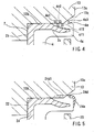
- the outer circumference of lips 4e1 and 4e3 is structured to be larger than that of the inner circumferential surface 13b of the outer ring 13, as shown in Fig. 3. Accordingly, the lip parts 4e1 and 4e2 are elastically deformed when they are pressed into the inner circumferential side of the outer ring 13, as shown in Fig. 4.
- the bottom diameters or circumference of the bottoms of the grooves 4f1 and 4f2 is structured to be smaller than that of the inner circumferential surface 13b of the outer ring 13. Therefore, a deformed part, generated by the elastic deformation of the lip parts 4e1 and 4e2, moves so as to fill the grooves 4f1 and 4f2 in, so that the grooves 4f1 and 4f2 offset the deformed part.
- one (4e3) of the lip parts 4e1 to 4e3 is structured to contact a surface of chamfered part 13c of the outer ring 13, as shown in Fig. 4.
- the chamfered part 13c is formed between the end surface 13a and the inner circumferential surface 13b of the outer ring 13.
- the lip part 4e3 is the last (the most right in Fig. 3) lip part in the press direction.
- the side surface (the left surface in Fig. 3) of the lip part 4e3 in the press direction is elastically in contact with the chamfered part 13c. Accordingly, the lip part 4e3 improves a sealing performance between the elastic body 4 and the outer ring 13.
- the sealing device 1 is formed as described above. That is to say, the sealing device 1 comprises the outer metal ring 2, the inner metal ring 3 and the elastic body 4, which has a ring shaped projection part 4e projecting from the outer metal ring 2 toward the outer ring 13 so as to be elastically in contact with the outer ring 13.
- the grooves 4f1 and 4f2 are positioned to extend substantially along the entire circumferential length of the projection part 4e.
- the projection part 4e of the elastic body 4 is elastically deformed when it is pressed into the outer ring 13 together with the outer metal ring 2, as shown in Fig. 4.
- the deformed part is able to move in a direction so that the grooves 4f1 and 4f2 of the projection part 4e are filled in.
- the grooves 4f1 and 4f2 prevent the elastic body 4 from being deformed from the end surface the elastic body (in a direction from the end surface 13a of the outer ring 13; refer to Fig. 4).
- the present invention reduces the likelihood interference with adjacent components or the hindrance of the measurement of quantity of depth.
- the projection part 4e of the elastic body 4 has the outer circumference or outer diameter that is larger than the inner circumference or inner diameter of the outer ring 13, as shown in Fig. 3.
- the circumference of the bottom of the grooves 4f1 and 4f2 (or bottom diameter) provided in the projection part 4e is smaller than the inner circumference or inner diameter of the outer ring 13.
- the outer ring 13 contacts the projection part 4e so that the projection part 4e is elastically deformed when the projection part 4e is pressed into the outer ring 13 together with the outer metal ring 2.
- the deformed part generated by the elastic deformation, thus can move so that that the grooves 4f1 and 4f2 are filled in be the deformed lip parts, since the grooves 4f1 and 4f2 are depressed below than the inner surface of the outer ring 13.
- the grooves 4f1 and 4f2 prevent the elastic body 4 from being deformed outwardly from the end of cover part 4g.
- the projection part 4e of the elastic body 4 can include a plurality of lip parts 4e1 to 4e3 by the grooves 4f1 and 4f2, as shown in Fig. 3.
- One (4e3) of the plural lip parts 4e1 to 4e3 can be structured to be in contact with a surface of the chamfered part 13c formed on the end surface 13a of the outer ring 13, as shown in Fig. 4.
- contact between the lip part 4e3 and the chamfered part 13c of the outer ring 13 can improve the sealing performance.
- the elastic body 4 can include a ring shaped projection part 4e projected toward the inner ring and pressed into the outer circumferential surface of the inner ring and the grooves 4f1 and 4f2 can be positioned along substantially the entire circumferential length of the projection part 4e.
- the grooves are provided in the projection part in two rows in the above-mentioned embodiment.
- the grooves may be provided only in one row or in three or more rows.
- the metal ring 3 is provided to be in contact slidably with the elastic body 4, as shown in Fig. 2. It may be possible, however, to provide no metal ring to be in slidable contact with the elastic body.
- the elastic body may directly contact with the inner ring or the outer ring so as to be slidable.
- the sealing device includes a metal ring connected to one of the inner and outer rings, an elastic body mounted to the metal ring and to be slidably contacted with the other of the both rings, and the elastic body includes a projection part projected from the metal ring to the one of the inner or outer rings, the projection part is able to contact with the one of the inner or outer rings by pressure, and a groove is provided along the entire circumferential length of the projection part.
- a sealing device (1) can include a bearing (11) having a first ring (13) and a second ring (12), a metal ring (2) connected to the first ring (13), and an elastic body (4) connected to the metal ring (2).
- the elastic body (4) includes a projection part (4e) having a lip part extending from the metal ring toward the first ring (13) so as to be elastically in contact with the first ring (13) and grooves (4f1,4f2) positioned adjacent the lip parts.
Landscapes
- Engineering & Computer Science (AREA)
- General Engineering & Computer Science (AREA)
- Mechanical Engineering (AREA)
- Sealing Of Bearings (AREA)
- Sealing With Elastic Sealing Lips (AREA)
Abstract
Description
- This application claims priority to
Japanese patent application serial number 2006-195369 - The invention relates to a sealing device for a bearing comprising a metal ring and an elastic body. The metal ring is mounted on an inner ring or an outer ring of the bearing. The elastic body is mounted to the metal ring and seals a space between the inner ring and the outer ring.
- Various kinds of sealing device for a bearing such as a sealing device described in
JP-A-2001-65704 JP-A-2001-65704 - The
conventional projection part 24d shown in Fig. 5, however, has a problem. That is to say, theprojection part 24d is in the shape of a simple convex. Accordingly, theprojection part 24d is elastically deformed when it is pressed into theouter ring 13. A projection portion 24d1, when deformed, createsdeformed part 24a due to the elastic deformation. Thedeformed part 24a projects from anend surface 13a of theouter ring 13, and thus deformedpart 24a interferes with components adjacent to the bearing. Also, thedeformed part 24a causes difficulty in measuring the quantity of depth of the sealing device into the bearing. This is problematic because the quantity of press of the sealing device into the bearing cannot be fixed. - Thus, there is need in the art for a sealing device having a projection that, when deformed, does not result in a deformed shape that interferes with adjacent components or hinder the measurement of quantity of depth.
- One aspect of the present invention can include a sealing device including a bearing having a first ring and a second ring, a metal ring connected to the first ring, an elastic body connected to the metal ring. The elastic body includes a projection part having a lip part extending from the metal ring toward the first ring so as to be elastically in contact with the first ring and a groove positioned adjacent the lip parts. The groove is provided along the entire circumferential of the projection part.
- Therefore, the projection part of the elastic body is elastically deformed when it is pressed into the first ring together with the metal ring. The deformed part, generated by the elastic deformation, then moves towards or into the groove. Thus the groove prevents the elastic body from being deformed or projected from an end surface of the elastic body.
- In another aspect of the present invention, the elastic body is mounted to the metal ring mounted on an inner circumferential surface of the outer ring. The projection part of the elastic body has an outer diameter larger than the inner circumference or inner diameter of the outer ring. The bottom circumference of the groove is smaller than the inner circumference of the outer ring.
- Accordingly, the outer ring presses the projection part so that the projection part elastically deforms when the projection part is pressed into the outer ring together with the metal ring. The deformed projection part thus can move towards the groove. Thus the groove prevents the elastic body from being deformed from the end surface of the elastic body.
- In another aspect of the present invention, the projection part includes a plurality of lip parts adjacent the groove. And, at least one of the plurality of lip parts is in contact with a surface of a chamfered part formed on an end surface of the one of the both rings.
- Accordingly, the contact of the lip part with the chamfered part of the ring can improve sealing performance between the lip part and the chamfered part.
- Additional objects, features, and advantages, of the present invention will be readily understood after reading the following detailed description together with the claims and the accompanying drawings, in which:
- FIG. 1 is a cross-sectional view of a sealing device for a bearing of a wheel;
- FIG. 2 is an enlarged cross-sectional view of a part of the sealing device;
- FIG. 3 is an enlarged cross-sectional view of a part of the sealing device before the sealing device is pressed into the bearing;
- FIG. 4 is an enlarged cross-sectional view of the part of the sealing device after the sealing device is pressed into the bearing; and
- FIG. 5 is an enlarged cross-sectional view of a part of a conventional sealing device after the sealing device is pressed into a bearing.
- Each of the additional features and teachings disclosed above and below may be utilized separately or in conjunction with other features and teachings to provide improved sealing devices for bearings. Representative examples of the present invention, which examples utilize many of these additional features and teachings both separately and in conjunction with one another, will now be described in detail with reference to the attached drawings. This detailed description is merely intended to teach a person of skill in the art further details for practicing preferred aspects of the present teachings and is not intended to limit the scope of the invention. Only the claims define the scope of the claimed invention. Therefore, combinations of features and steps disclosed in the following detailed description may not be necessary to practice the invention in the broadest sense, and are instead taught merely to particularly describe representative examples of the invention. Moreover, various features of the representative examples and the dependent claims may be combined in ways that are not specifically enumerated in order to provide additional useful configurations of the present teachings.
- The
sealing device 1 of the present invention can be used in a rollingbearing 11 for a bearing device for a wheel (a hub unit) 10, as shown in Fig. 1. - The rolling
bearing 11 can include aninner ring 12 and anouter ring 13 as shown in Fig. 1. Theouter ring 13 has ahub 16 on the outer circumferential surface, which can be formed integrally. A wheel (not shown) can be mounted to thehub 16.Rolling elements 14 are rotatably provided between theinner ring 12 and theouter ring 13 in two rows. Theroling elements 14 in the respective rows can be held by way ofcages 15 at predetermined intervals. - The
sealing device 1 has anouter metal ring 2, aninner metal ring 3 and anelastic body 4 that can function as a seal between theinner ring 12 and theouter ring 13, as shown in Fig. 2. Themetal rings metal rings cylinder parts vertical parts vertical parts cylinder parts other cylinder parts cylinder parts vertical parts - In this embodiment, the outer metal ring (a first metal ring) 2 can be structured to have a circumference (or diameter) larger than the inner metal ring (a second metal ring) 3 and can be positioned on the outer circumferential side of the
inner metal ring 3, as shown in Figs. 2 and 3. Theouter metal ring 2 is pressed into the inner circumferential side of theouter ring 13 so that thecylinder part 2a is connectable on an inner circumferential surface of theouter ring 13. On the other hand, theinner metal ring 3 can be pressed into the outer circumferential side of theinner ring 12 so that thecylinder part 3a is connectable on the outer circumferential surface of theinner ring 12. Thevertical parts elastic body 4. - The
elastic body 4 can be made of rubber or synthetic resin. Theelastic body 4 can be formed into one body with theouter metal ring 2, as shown in Figs. 2 and 3. Theelastic body 4 has amain body part 4a, aside lip 4b and tworadial lips 4c and 4d. Themain body 4a can have a substantially L-shaped cross-section and positioned over thecylinder part 2a of themetal ring 2 and thevertical part 2b. Theside lip 4b and theradial lips 4c and 4d extend from themain body part 4a toward thevertical part 3b and thecylinder part 3a of theinner metal ring 3, respectively. - The
side lip 4b obliquely extends outward in the diameter direction from the top end (the lower end) of the inner circumference of themain body part 4a, and thus is able to contactvertical part 3b, as shown in Figs. 2 and 3. Theradial lips 4c and 4d diverge in the axial direction from the radial inner top end of themain body part 4a, and thus are able to contact the outer circumferential surface of thecylinder part 3a. Accordingly, theside lip 4b and theradial lips 4c and 4d slide on theinner metal ring 3 as theinner ring 12 and theouter ring 13 relatively rotate. - The
elastic body 4 further includes acover part 4g and aprojection part 4e, as shown in Figs. 2 and 3. Thecover part 4g extends from themain body part 4a so as to cover the end part of thecylinder part 2a. Thecover part 4g extends along inner circumferential surface, tip end and outer circumferential surface of thecylinder part 2a. - The
projection part 4e is structured to extend outward, in the diameter direction, from thecover part 4g and outward beyond the most outer circumferential surface of thecylinder part 2a of themetal ring 2, as shown in Fig. 3. Theprojection part 4e is provided along the length of the outer circumference of thecylinder part 2a and formed into a ring shape. Theprojection part 4e is provided with plural grooves 4f1 and 4f2. - The grooves 4f1 and 4f2 are formed in the diameter direction from the outer circumferential surface side of the
projection part 4e and extends along substantially the entire circumferential length of theprojection part 4e, as shown in Fig. 3. Accordingly, theprojection part 4e can be divided into plural annular lip parts 4e1, to 4e3 by the grooves 4f1 and 4f2. The lip parts 4e1 to 4e3 can be formed parallel in the axial direction. - The lip parts 4e1 to 4e3 represents an outer circumference of
elastic part 4. The outer circumference of lips 4e1 and 4e3 is structured to be larger than that of the innercircumferential surface 13b of theouter ring 13, as shown in Fig. 3. Accordingly, the lip parts 4e1 and 4e2 are elastically deformed when they are pressed into the inner circumferential side of theouter ring 13, as shown in Fig. 4. On the other hand, the bottom diameters or circumference of the bottoms of the grooves 4f1 and 4f2 is structured to be smaller than that of the innercircumferential surface 13b of theouter ring 13. Therefore, a deformed part, generated by the elastic deformation of the lip parts 4e1 and 4e2, moves so as to fill the grooves 4f1 and 4f2 in, so that the grooves 4f1 and 4f2 offset the deformed part. - In this embodiment, one (4e3) of the lip parts 4e1 to 4e3 is structured to contact a surface of
chamfered part 13c of theouter ring 13, as shown in Fig. 4. Thechamfered part 13c is formed between theend surface 13a and the innercircumferential surface 13b of theouter ring 13. The lip part 4e3 is the last (the most right in Fig. 3) lip part in the press direction. The side surface (the left surface in Fig. 3) of the lip part 4e3 in the press direction is elastically in contact with thechamfered part 13c. Accordingly, the lip part 4e3 improves a sealing performance between theelastic body 4 and theouter ring 13. - The
sealing device 1 is formed as described above. That is to say, thesealing device 1 comprises theouter metal ring 2, theinner metal ring 3 and theelastic body 4, which has a ring shapedprojection part 4e projecting from theouter metal ring 2 toward theouter ring 13 so as to be elastically in contact with theouter ring 13. The grooves 4f1 and 4f2 are positioned to extend substantially along the entire circumferential length of theprojection part 4e. - Accordingly, the
projection part 4e of theelastic body 4 is elastically deformed when it is pressed into theouter ring 13 together with theouter metal ring 2, as shown in Fig. 4. The deformed part is able to move in a direction so that the grooves 4f1 and 4f2 of theprojection part 4e are filled in. Thus the grooves 4f1 and 4f2 prevent theelastic body 4 from being deformed from the end surface the elastic body (in a direction from theend surface 13a of theouter ring 13; refer to Fig. 4). Thus, the present invention reduces the likelihood interference with adjacent components or the hindrance of the measurement of quantity of depth. - Further, the
projection part 4e of theelastic body 4 has the outer circumference or outer diameter that is larger than the inner circumference or inner diameter of theouter ring 13, as shown in Fig. 3. The circumference of the bottom of the grooves 4f1 and 4f2 (or bottom diameter) provided in theprojection part 4e is smaller than the inner circumference or inner diameter of theouter ring 13. - Accordingly, the
outer ring 13 contacts theprojection part 4e so that theprojection part 4e is elastically deformed when theprojection part 4e is pressed into theouter ring 13 together with theouter metal ring 2. The deformed part, generated by the elastic deformation, thus can move so that that the grooves 4f1 and 4f2 are filled in be the deformed lip parts, since the grooves 4f1 and 4f2 are depressed below than the inner surface of theouter ring 13. Thus the grooves 4f1 and 4f2 prevent theelastic body 4 from being deformed outwardly from the end ofcover part 4g. - Moreover, the
projection part 4e of theelastic body 4 can include a plurality of lip parts 4e1 to 4e3 by the grooves 4f1 and 4f2, as shown in Fig. 3. One (4e3) of the plural lip parts 4e1 to 4e3 can be structured to be in contact with a surface of thechamfered part 13c formed on theend surface 13a of theouter ring 13, as shown in Fig. 4. - Accordingly, contact between the lip part 4e3 and the
chamfered part 13c of theouter ring 13 can improve the sealing performance. - While the invention has been described with reference to specific configurations, it will be apparent to those skilled in the art that many alternatives, modifications and variations may be made. Accordingly, the present invention is intended to embring all such alternatives, modifications and variations that may fall within the spirit and scope of the appended claims. For example, the present invention should not be limited to the representative configurations, but may be modified as described below.
- (1) For example it may be possible that 13 shown in Figs. 2 to 4 denotes not an outer ring but an inner ring, 12 denotes not an inner ring but an outer ring, 2 denotes a first metal ring connectable to the inner ring, 3 denotes a second metal ring connectable to the outer ring, the
elastic body 4 can include a ring shapedprojection part 4e projected toward the inner ring and pressed into the outer circumferential surface of the inner ring and the grooves 4f1 and 4f2 can be positioned along substantially the entire circumferential length of theprojection part 4e. - (2) The grooves are provided in the projection part in two rows in the above-mentioned embodiment. The grooves, however, may be provided only in one row or in three or more rows.
- (3) In the above-mentioned embodiment, the
metal ring 3 is provided to be in contact slidably with theelastic body 4, as shown in Fig. 2. It may be possible, however, to provide no metal ring to be in slidable contact with the elastic body. The elastic body may directly contact with the inner ring or the outer ring so as to be slidable. That is to say, it may be possible that the sealing device includes a metal ring connected to one of the inner and outer rings, an elastic body mounted to the metal ring and to be slidably contacted with the other of the both rings, and the elastic body includes a projection part projected from the metal ring to the one of the inner or outer rings, the projection part is able to contact with the one of the inner or outer rings by pressure, and a groove is provided along the entire circumferential length of the projection part.
A sealing device (1) can include a bearing (11) having a first ring (13) and a second ring (12), a metal ring (2) connected to the first ring (13), and an elastic body (4) connected to the metal ring (2). The elastic body (4) includes a projection part (4e) having a lip part extending from the metal ring toward the first ring (13) so as to be elastically in contact with the first ring (13) and grooves (4f1,4f2) positioned adjacent the lip parts.
Claims (6)
- A sealing device (1) for a bearing (11) comprising:an inner ring (12) and an outer ring (13) of the bearing, the inner ring (12) and the outer ring (13) capable of relatively rotating;a metal ring (2) connected to one of the inner and outer ring (12,13); andan elastic body (4) connected to the metal ring (2),wherein the elastic body (4) includes a projection part (4e) extending from the metal ring (2) toward the one of the inner and outer race (12,13) so as to be elastically in contact with the one of the inner and outer race (12,13), and a groove (4f1,4f1).
- The sealing device (1) as in claim 1, wherein
a second metal ring (3) connected to the other of the inner and outer ring (12,13), further
wherein the elastic body (4) is capable of slidably contacting with the second metal ring (3). - The sealing device (1) as in claim 1,
wherein the metal ring (2) is mounted on an inner circumferential surface (13b) of the outer ring (13),
the projection part (4e) of the elastic body (4) has an outer circumferential diameter larger than the inner circumferential diameter of the outer ring (13), and
the groove provided in the projection part (4e) has a bottom diameter smaller than the inner circumferential diameter of the outer ring (13). - The sealing device (1) as in claim 1, wherein the projection part (4e) of the elastic body (4) includes a plurality of lip parts (4e1,4e2,4e3) positioned by the grooves (4f1,4f2), and one of the plurality lip parts (4e1,4e2,4e3) is capable of contacting a surface of a chamfered part (13c) on an end surface of the one of the inner and outer ring (12,13).
- The sealing device (1) as in claim 1, wherein the elastic body (4) slidably contacts with the other of the inner and outer ring (12,13).
- The sealing device (1) as in claim 1, wherein the groove (4f1,4f2) is positioned along substantially the entire circumferential length of the projection part (4e).
Applications Claiming Priority (1)
| Application Number | Priority Date | Filing Date | Title |
|---|---|---|---|
| JP2006195369A JP2008025600A (en) | 2006-07-18 | 2006-07-18 | Sealing device for bearing |
Publications (2)
| Publication Number | Publication Date |
|---|---|
| EP1881217A2 true EP1881217A2 (en) | 2008-01-23 |
| EP1881217A3 EP1881217A3 (en) | 2011-03-16 |
Family
ID=38626355
Family Applications (1)
| Application Number | Title | Priority Date | Filing Date |
|---|---|---|---|
| EP07112344A Withdrawn EP1881217A3 (en) | 2006-07-18 | 2007-07-12 | Sealing device for bearings |
Country Status (3)
| Country | Link |
|---|---|
| US (1) | US20080019624A1 (en) |
| EP (1) | EP1881217A3 (en) |
| JP (1) | JP2008025600A (en) |
Cited By (1)
| Publication number | Priority date | Publication date | Assignee | Title |
|---|---|---|---|---|
| US20160091027A1 (en) * | 2014-09-30 | 2016-03-31 | Aktiebolaget Skf | Universal joint |
Families Citing this family (8)
| Publication number | Priority date | Publication date | Assignee | Title |
|---|---|---|---|---|
| JP5376211B2 (en) * | 2008-08-08 | 2013-12-25 | 株式会社ジェイテクト | Rolling bearing device |
| CN104094004B (en) * | 2012-01-02 | 2018-02-09 | Skf公司 | A kind of large sealing self-aligning roller bearing |
| US20130307228A1 (en) | 2012-05-18 | 2013-11-21 | Freudenberg-Nok General Partnership | Low Load Seal With Outer Diameter Flap |
| CN102777500A (en) * | 2012-07-30 | 2012-11-14 | 湖北新火炬科技股份有限公司 | Hub bearing unit with four-lip seal structure |
| ITTO20120845A1 (en) * | 2012-09-27 | 2014-03-28 | Skf Ab | HOLDING DEVICE, IN PARTICULAR FOR MOTORCYCLE WHEEL HUBS |
| US10935137B2 (en) | 2016-11-10 | 2021-03-02 | Hutchinson | Seal assembly, roller bearing comprising such an assembly, and method for manufacturing this assembly |
| JP2020084996A (en) * | 2018-11-15 | 2020-06-04 | Nok株式会社 | Oil seal and its mounting method |
| IT202200014851A1 (en) * | 2022-07-15 | 2024-01-15 | Skf Ab | ROLLING ELEMENT BEARING UNIT |
Citations (1)
| Publication number | Priority date | Publication date | Assignee | Title |
|---|---|---|---|---|
| JP2001065704A (en) | 1999-08-31 | 2001-03-16 | Ntn Corp | Sealing device |
Family Cites Families (11)
| Publication number | Priority date | Publication date | Assignee | Title |
|---|---|---|---|---|
| US3356376A (en) * | 1964-05-11 | 1967-12-05 | Federal Mogul Corp | Axle seal |
| US4015883A (en) * | 1973-10-23 | 1977-04-05 | Skf Industrial Trading And Development Company, B.V. | Annular sealing members and assemblies incorporating them |
| US4252329A (en) * | 1979-02-26 | 1981-02-24 | Garlock Inc. | Semi-unitized shaft seal |
| IT1211622B (en) * | 1987-12-23 | 1989-11-03 | Riv Officine Di Villar Perosa | SEALING SCREEN IN PARTICULAR FOR A ROLLING BEARING WITH A PERFECT TYPE ANCHORING DEVICE |
| IT223225Z2 (en) * | 1991-07-16 | 1995-06-13 | Skf Ind Spa | SEALING COMPLEX, PARTICULARLY FOR A ROLLING BEARING. |
| US5997005A (en) * | 1997-10-24 | 1999-12-07 | Stemco Inc | Hub seal with machinable thrust ring |
| JPH11248005A (en) * | 1998-03-03 | 1999-09-14 | Toyota Autom Loom Works Ltd | Seal structure of housing |
| DE10037530A1 (en) * | 1999-08-31 | 2001-03-22 | Ntn Toyo Bearing Co Ltd | Seal for bearing comprises two sealing plates which seal gap between two raceways, radial sections of plates being arranged in contact with raceways so that seal has rectangular cross-section with flexible sealing component between |
| US6637754B1 (en) * | 1999-11-17 | 2003-10-28 | Ntn Corporation | Wheel bearing and sealing device therefor |
| JP2003035365A (en) * | 2001-07-24 | 2003-02-07 | Koyo Sealing Techno Co Ltd | Seal ring |
| JP2005331002A (en) * | 2004-05-19 | 2005-12-02 | Nok Corp | Sealing device |
-
2006
- 2006-07-18 JP JP2006195369A patent/JP2008025600A/en active Pending
-
2007
- 2007-07-12 EP EP07112344A patent/EP1881217A3/en not_active Withdrawn
- 2007-07-17 US US11/778,959 patent/US20080019624A1/en not_active Abandoned
Patent Citations (1)
| Publication number | Priority date | Publication date | Assignee | Title |
|---|---|---|---|---|
| JP2001065704A (en) | 1999-08-31 | 2001-03-16 | Ntn Corp | Sealing device |
Cited By (2)
| Publication number | Priority date | Publication date | Assignee | Title |
|---|---|---|---|---|
| US20160091027A1 (en) * | 2014-09-30 | 2016-03-31 | Aktiebolaget Skf | Universal joint |
| US9879732B2 (en) * | 2014-09-30 | 2018-01-30 | Aktiebolaget Skf | Universal joint |
Also Published As
| Publication number | Publication date |
|---|---|
| JP2008025600A (en) | 2008-02-07 |
| EP1881217A3 (en) | 2011-03-16 |
| US20080019624A1 (en) | 2008-01-24 |
Similar Documents
| Publication | Publication Date | Title |
|---|---|---|
| US20080019624A1 (en) | Sealing devices for bearings | |
| EP3339693B1 (en) | Sealing apparatus | |
| JP5633185B2 (en) | Rolling bearing | |
| US8246253B2 (en) | Rolling bearing | |
| US20040141672A1 (en) | Resin-made ball retainer for a rolling bearing | |
| EP2639468A2 (en) | Rolling bearing unit | |
| US20120170884A1 (en) | Triple-lip seals for bearings and bearings incorporating the same | |
| JP6740576B2 (en) | Ball bearing | |
| JP7296725B2 (en) | sealing device | |
| US20160017926A1 (en) | Bearing device with sealing device | |
| EP2034202B1 (en) | Resin cage for ball bearing | |
| JP2015200393A (en) | Rolling bearing with seal ring | |
| EP3633245B1 (en) | Sealing device | |
| JP2021063530A (en) | Rolling bearing | |
| EP2405153B1 (en) | Clutch release bearing device | |
| GB2087983A (en) | Antifriction bearing with removable seal means | |
| JP5266947B2 (en) | Ball bearing | |
| CN106989104A (en) | Rolling bearing | |
| JP2008240776A (en) | Angular contact ball bearing | |
| JP3201303U (en) | Sealing device | |
| EP2500592A1 (en) | Sealing device, notably for a rolling bearing | |
| JP6960818B2 (en) | Sealing device | |
| JP2008128378A (en) | Sealing device | |
| JP4748050B2 (en) | Sealed thrust ball bearing | |
| JP2007155028A (en) | Rolling bearing and its cage |
Legal Events
| Date | Code | Title | Description |
|---|---|---|---|
| PUAI | Public reference made under article 153(3) epc to a published international application that has entered the european phase |
Free format text: ORIGINAL CODE: 0009012 |
|
| AK | Designated contracting states |
Kind code of ref document: A2 Designated state(s): AT BE BG CH CY CZ DE DK EE ES FI FR GB GR HU IE IS IT LI LT LU LV MC MT NL PL PT RO SE SI SK TR |
|
| AX | Request for extension of the european patent |
Extension state: AL BA HR MK YU |
|
| 17P | Request for examination filed |
Effective date: 20080527 |
|
| PUAL | Search report despatched |
Free format text: ORIGINAL CODE: 0009013 |
|
| AK | Designated contracting states |
Kind code of ref document: A3 Designated state(s): AT BE BG CH CY CZ DE DK EE ES FI FR GB GR HU IE IS IT LI LT LU LV MC MT NL PL PT RO SE SI SK TR |
|
| AX | Request for extension of the european patent |
Extension state: AL BA HR MK RS |
|
| RIC1 | Information provided on ipc code assigned before grant |
Ipc: F16J 15/32 20060101ALI20110204BHEP Ipc: F16C 33/76 20060101ALI20110204BHEP Ipc: F16C 33/74 20060101ALI20110204BHEP Ipc: F16C 33/78 20060101AFI20071107BHEP |
|
| AKX | Designation fees paid |
Designated state(s): DE FR |
|
| STAA | Information on the status of an ep patent application or granted ep patent |
Free format text: STATUS: THE APPLICATION IS DEEMED TO BE WITHDRAWN |
|
| 18D | Application deemed to be withdrawn |
Effective date: 20110917 |