EP1881198A2 - Fuel leak detection apparatus and method - Google Patents
Fuel leak detection apparatus and method Download PDFInfo
- Publication number
- EP1881198A2 EP1881198A2 EP07075533A EP07075533A EP1881198A2 EP 1881198 A2 EP1881198 A2 EP 1881198A2 EP 07075533 A EP07075533 A EP 07075533A EP 07075533 A EP07075533 A EP 07075533A EP 1881198 A2 EP1881198 A2 EP 1881198A2
- Authority
- EP
- European Patent Office
- Prior art keywords
- fuel
- enclosure
- pump
- detector
- leak
- Prior art date
- Legal status (The legal status is an assumption and is not a legal conclusion. Google has not performed a legal analysis and makes no representation as to the accuracy of the status listed.)
- Withdrawn
Links
- 239000000446 fuel Substances 0.000 title claims abstract description 175
- 238000000034 method Methods 0.000 title claims abstract description 16
- 238000001514 detection method Methods 0.000 title claims description 17
- 238000012544 monitoring process Methods 0.000 claims description 10
- 229930195733 hydrocarbon Natural products 0.000 claims description 6
- 150000002430 hydrocarbons Chemical class 0.000 claims description 6
- LFQSCWFLJHTTHZ-UHFFFAOYSA-N Ethanol Chemical compound CCO LFQSCWFLJHTTHZ-UHFFFAOYSA-N 0.000 claims description 5
- QVGXLLKOCUKJST-UHFFFAOYSA-N atomic oxygen Chemical compound [O] QVGXLLKOCUKJST-UHFFFAOYSA-N 0.000 claims description 4
- 239000001301 oxygen Substances 0.000 claims description 4
- 229910052760 oxygen Inorganic materials 0.000 claims description 4
- UFHFLCQGNIYNRP-UHFFFAOYSA-N Hydrogen Chemical compound [H][H] UFHFLCQGNIYNRP-UHFFFAOYSA-N 0.000 claims description 3
- 239000001257 hydrogen Substances 0.000 claims description 3
- 229910052739 hydrogen Inorganic materials 0.000 claims description 3
- 238000002347 injection Methods 0.000 claims description 2
- 239000007924 injection Substances 0.000 claims description 2
- 239000004215 Carbon black (E152) Substances 0.000 description 3
- 239000002828 fuel tank Substances 0.000 description 3
- 230000000246 remedial effect Effects 0.000 description 3
- 239000000203 mixture Substances 0.000 description 2
- WYTGDNHDOZPMIW-RCBQFDQVSA-N alstonine Natural products C1=CC2=C3C=CC=CC3=NC2=C2N1C[C@H]1[C@H](C)OC=C(C(=O)OC)[C@H]1C2 WYTGDNHDOZPMIW-RCBQFDQVSA-N 0.000 description 1
- 238000002485 combustion reaction Methods 0.000 description 1
- 230000008878 coupling Effects 0.000 description 1
- 238000010168 coupling process Methods 0.000 description 1
- 238000005859 coupling reaction Methods 0.000 description 1
- 230000003247 decreasing effect Effects 0.000 description 1
- 230000007613 environmental effect Effects 0.000 description 1
- 239000003502 gasoline Substances 0.000 description 1
- 230000006698 induction Effects 0.000 description 1
- 239000007788 liquid Substances 0.000 description 1
- 238000005086 pumping Methods 0.000 description 1
Images
Classifications
-
- F—MECHANICAL ENGINEERING; LIGHTING; HEATING; WEAPONS; BLASTING
- F04—POSITIVE - DISPLACEMENT MACHINES FOR LIQUIDS; PUMPS FOR LIQUIDS OR ELASTIC FLUIDS
- F04B—POSITIVE-DISPLACEMENT MACHINES FOR LIQUIDS; PUMPS
- F04B49/00—Control, e.g. of pump delivery, or pump pressure of, or safety measures for, machines, pumps, or pumping installations, not otherwise provided for, or of interest apart from, groups F04B1/00 - F04B47/00
-
- F—MECHANICAL ENGINEERING; LIGHTING; HEATING; WEAPONS; BLASTING
- F02—COMBUSTION ENGINES; HOT-GAS OR COMBUSTION-PRODUCT ENGINE PLANTS
- F02M—SUPPLYING COMBUSTION ENGINES IN GENERAL WITH COMBUSTIBLE MIXTURES OR CONSTITUENTS THEREOF
- F02M37/00—Apparatus or systems for feeding liquid fuel from storage containers to carburettors or fuel-injection apparatus; Arrangements for purifying liquid fuel specially adapted for, or arranged on, internal-combustion engines
-
- F—MECHANICAL ENGINEERING; LIGHTING; HEATING; WEAPONS; BLASTING
- F04—POSITIVE - DISPLACEMENT MACHINES FOR LIQUIDS; PUMPS FOR LIQUIDS OR ELASTIC FLUIDS
- F04B—POSITIVE-DISPLACEMENT MACHINES FOR LIQUIDS; PUMPS
- F04B51/00—Testing machines, pumps, or pumping installations
Definitions
- the present invention relates to fuel leak detection for fuel containing devices.
- the invention relates to an apparatus and method for detecting a fuel leak in a fuel pump of the fuel system of a vehicle.
- Fuel systems for driving machinery or engines include various components such as a fuel tank, fuel lines for delivering the fuel to the engine, fuel pumps for pumping the fuel from the tank through the fuel lines to the engine, and fuel injectors for injecting fuel into a respective cylinder, for example.
- Fuel leaks (both liquid and vapor) may occur in any part of the fuel system and it is desirable to be alerted to such leaks at the earliest possible moment. Furthermore, due to environmental concerns and engine operating efficiency, it is desirable to prevent passage of leaked fuel into the atmosphere or into or onto surrounding components.
- one potential source of a fuel leak is at the mechanical rotary or reciprocating pump seal of a high pressure fuel pump in a vehicle fuel system.
- Direct injected gasoline engines require fuel pressures as high as 20MPa to operate.
- the fuel pressure is normally generated by a mechanical engine-driven fuel pump.
- This high pressure fuel pump can be either directly mounted to the engine and driven from a dedicated cam lobe on the camshaft or a coupling driven from the end of the crankshaft, or remotely mounted and driven by the engine serpentine or a dedicated belt coming off the engine.
- a fuel leak enclosure is provided adjacent the component that is being monitored for a fuel leak.
- the component being monitored may be any component that comes into contact with fuel.
- such components may include the fuel tank, fuel lines, fuel rails, fuel pumps and fuel injectors, for example.
- the fuel leak enclosure is operable to capture the leaked fuel and substantially prevent the fuel from releasing to the atmosphere or surrounding components.
- an outlet port is provided in the enclosure which directs any fuel leaked into the enclosure to a fuel monitoring system which is operable to detect the leaked fuel. If fuel is detected from the enclosure, further fuel control measures may be taken as desired such as an adjustment to the fuel delivery rate.
- the fuel diagnostic system may be used to identify the source of the leaked fuel.
- a fuel detector is positioned in proximity to the fuel leak enclosure and provides a signal if fuel is detected in the enclosure so that remedial measures may be taken.
- the system detects fuel leaking from the piston or crank bearing seal of the fuel chamber of a fuel pump for a direct injection engine.
- a leak detection enclosure is provided externally of the pump's fuel chamber drive seal.
- the leak detection enclosure includes an outlet port that connects to a manifold vacuum source or the intake side of the PVC. Should the pump fuel chamber drive seal begin to fail, fuel will leak past the seal from the fuel chamber and into the leak detection enclosure, pass through the outlet port and enter the engine manifold.
- the air/fuel diagnostic system would detect an unexpectedly higher level of fuel and could be programmed to generate a diagnostic check or warning signal to the driver. For example, if an unexpected fuel level is detected, the diagnostic system can trigger a check engine or service engine code so that remedial measures may be initiated as soon as possible and preferably prior to complete seal failure.
- fuel leak detection is provided by a hydrocarbon detector positioned in proximity to the leak detection chamber.
- a hydrocarbon detector may be used to detect the type of fuel being used in a particular application.
- an alcohol detector may be used to detect an ethanol leak
- a hydrogen detector may be used to detect a hydrogen leak.
- FIG. 1 there is seen a schematic representation of an exemplary embodiment of the invention incorporated into a fuel pump 10 having a pump body 11, a low pressure fuel inlet 12 and a high pressure fuel outlet 14 for connecting to a fuel rail having fuel injectors for delivering fuel under pressure to the engine (fuel rail, injectors and engine are not shown).
- Fuel pump body 11 defines a fuel pump chamber 16 into which fuel is delivered from the fuel tank via inlet 12.
- a reciprocating piston 18 compresses the fuel during the advance stroke to deliver fuel under high pressure to the fuel rail via fuel outlet 14.
- Piston rod 20 may be driven by lobe 22 of cam shaft 24 although other mounting locations and drive means for operating fuel pump 10 may be used as dictated by the particular engine design being employed (e.g., a rotary driven pump or remotely mounted cambox system). It is therefore understood that this embodiment of the invention is not limited to the reciprocating pump design illustrated in Fig. 1.
- fuel pump 10 is fit with a "wet" seal ring 25 to prevent fuel from leaking out of fuel pump chamber 16 between the interfacing surfaces of piston 18 (including rod 20) and pump body 11.
- a fuel leak enclosure 26 is provided on the side of piston 18 opposite fuel chamber 16.
- a second "dry” seal ring 28 is provided adjacent the base 11a of pump body 11 such that leak detection enclosure 26 is defined by first seal ring 25, pump body 11, rod 20 and second seal ring 28. It will be appreciated that as rod 20 reciprocates, both first seal ring 25 and second seal ring 28 remain stationary with respect to the pump body 11.
- An outlet port 30 extends from leak detection 26 through pump body 11 for connecting to a line 32 ultimately leading to the engine induction system.
- the leaked fuel will be drawn into the engine by the manifold vacuum.
- the leaked fuel combines with the air/fuel mixture entering the engine. This of course increases the amount of fuel in the air/fuel mixture and this is detected by the vehicle's fuel monitoring system.
- Present day vehicle closed loop fuel systems monitor the fuel delivery rate and can make real time adjustments to the rate of fuel delivery to maintain proper fuel control and emissions.
- closed loop fuel systems measure the oxygen level at the exhaust manifold to determine if the rate of fuel delivery is producing a combustion exhaust that is rich or lean. Based on the detected oxygen level and engine operating condition, the rate of fuel delivery may be increased or decreased to achieve the optimum air/fuel ratio input.
- a block learn multiplier (“BLM”) may also be employed to calculate correction factors and make necessary adjustments to the fuel delivery rate to help keep the air/fuel ratio at the most efficient operating level.
- a diagnostic component such as a solenoid 33, for example, may be positioned along line 32 to indicate whether or not the pump 10 is the source of the unexpected high fuel level. If the fuel monitoring system detects a higher than normal fuel level, the solenoid 33 may be activated to close line 32. If the fuel level drops back to expected ranges, then a leaking pump 10 is identified as the source of the unexpectedly high fuel level. If no change in fuel level is detected by the monitoring system when the solenoid is activated, the pump 10 may be ruled out as the source of the high fuel level and other sources may then be investigated.
- a diagnostic component such as a solenoid 33, for example, may be positioned along line 32 to indicate whether or not the pump 10 is the source of the unexpected high fuel level. If the fuel monitoring system detects a higher than normal fuel level, the solenoid 33 may be activated to close line 32. If the fuel level drops back to expected ranges, then a leaking pump 10 is identified as the source of the unexpectedly high fuel level. If no change in fuel
- a hydrocarbon or other fuel detector 36 is positioned inside or in close proximity to fuel leak enclosure 26. In this embodiment, an outlet port 30 and line 32 are not required. Hydrocarbon detector 36 may connect to the fuel monitoring system to provide a signal when a predetermined threshold of hydrocarbons (or other fuel molecules or atoms) are detected in enclosure 26.
- the present inventive fuel leak detection system allows for detection of a fuel leak at the earliest possible moment. Since the leaked fuel is captured in the leak detection enclosure 26, leaked fuel is not released to the atmosphere or surrounding components. Early alert of the leak allows for quick remedial measures to be taken and thereby hopefully avoiding a total seal and pump failure.
Landscapes
- Engineering & Computer Science (AREA)
- Mechanical Engineering (AREA)
- General Engineering & Computer Science (AREA)
- Chemical & Material Sciences (AREA)
- Combustion & Propulsion (AREA)
- Electrical Control Of Air Or Fuel Supplied To Internal-Combustion Engine (AREA)
Abstract
Apparatus and method for detecting a fuel leak from a component includes providing a fuel leak enclosure about the component being monitored.
Description
- The present invention relates to fuel leak detection for fuel containing devices. In one particularly advantageous embodiment, the invention relates to an apparatus and method for detecting a fuel leak in a fuel pump of the fuel system of a vehicle.
- Fuel systems for driving machinery or engines include various components such as a fuel tank, fuel lines for delivering the fuel to the engine, fuel pumps for pumping the fuel from the tank through the fuel lines to the engine, and fuel injectors for injecting fuel into a respective cylinder, for example. Fuel leaks (both liquid and vapor) may occur in any part of the fuel system and it is desirable to be alerted to such leaks at the earliest possible moment. Furthermore, due to environmental concerns and engine operating efficiency, it is desirable to prevent passage of leaked fuel into the atmosphere or into or onto surrounding components.
- For example, one potential source of a fuel leak is at the mechanical rotary or reciprocating pump seal of a high pressure fuel pump in a vehicle fuel system. Direct injected gasoline engines require fuel pressures as high as 20MPa to operate. The fuel pressure is normally generated by a mechanical engine-driven fuel pump. This high pressure fuel pump can be either directly mounted to the engine and driven from a dedicated cam lobe on the camshaft or a coupling driven from the end of the crankshaft, or remotely mounted and driven by the engine serpentine or a dedicated belt coming off the engine.
- The present invention addresses the above need by providing a unique fuel leak detection system. In a broad aspect of the invention, a fuel leak enclosure is provided adjacent the component that is being monitored for a fuel leak. The component being monitored may be any component that comes into contact with fuel. In a vehicle, such components may include the fuel tank, fuel lines, fuel rails, fuel pumps and fuel injectors, for example.
- The fuel leak enclosure is operable to capture the leaked fuel and substantially prevent the fuel from releasing to the atmosphere or surrounding components. In one embodiment of the invention, an outlet port is provided in the enclosure which directs any fuel leaked into the enclosure to a fuel monitoring system which is operable to detect the leaked fuel. If fuel is detected from the enclosure, further fuel control measures may be taken as desired such as an adjustment to the fuel delivery rate. In yet a further embodiment, the fuel diagnostic system may be used to identify the source of the leaked fuel. In yet another alternate embodiment of the invention, a fuel detector is positioned in proximity to the fuel leak enclosure and provides a signal if fuel is detected in the enclosure so that remedial measures may be taken.
- In one exemplary application of the invention, the system detects fuel leaking from the piston or crank bearing seal of the fuel chamber of a fuel pump for a direct injection engine. In a preferred embodiment, a leak detection enclosure is provided externally of the pump's fuel chamber drive seal. The leak detection enclosure includes an outlet port that connects to a manifold vacuum source or the intake side of the PVC. Should the pump fuel chamber drive seal begin to fail, fuel will leak past the seal from the fuel chamber and into the leak detection enclosure, pass through the outlet port and enter the engine manifold. The air/fuel diagnostic system would detect an unexpectedly higher level of fuel and could be programmed to generate a diagnostic check or warning signal to the driver. For example, if an unexpected fuel level is detected, the diagnostic system can trigger a check engine or service engine code so that remedial measures may be initiated as soon as possible and preferably prior to complete seal failure.
- In an alternate embodiment, fuel leak detection is provided by a hydrocarbon detector positioned in proximity to the leak detection chamber. Different fuel detectors may be used to detect the type of fuel being used in a particular application. For example, an alcohol detector may be used to detect an ethanol leak, and a hydrogen detector may be used to detect a hydrogen leak.
- The present invention will now be described, by way of example, with reference to the accompanying drawings, in which:
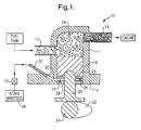
- FIG. 1 is a cross sectional schematic of an embodiment of the invention.
- Referring to FIG. 1, there is seen a schematic representation of an exemplary embodiment of the invention incorporated into a fuel pump 10 having a
pump body 11, a lowpressure fuel inlet 12 and a highpressure fuel outlet 14 for connecting to a fuel rail having fuel injectors for delivering fuel under pressure to the engine (fuel rail, injectors and engine are not shown).Fuel pump body 11 defines afuel pump chamber 16 into which fuel is delivered from the fuel tank viainlet 12. A reciprocatingpiston 18 compresses the fuel during the advance stroke to deliver fuel under high pressure to the fuel rail viafuel outlet 14. Pistonrod 20 may be driven bylobe 22 ofcam shaft 24 although other mounting locations and drive means for operating fuel pump 10 may be used as dictated by the particular engine design being employed (e.g., a rotary driven pump or remotely mounted cambox system). It is therefore understood that this embodiment of the invention is not limited to the reciprocating pump design illustrated in Fig. 1. - As known in the art, fuel pump 10 is fit with a "wet"
seal ring 25 to prevent fuel from leaking out offuel pump chamber 16 between the interfacing surfaces of piston 18 (including rod 20) andpump body 11. According to a preferred embodiment of the invention, afuel leak enclosure 26 is provided on the side ofpiston 18opposite fuel chamber 16. A second "dry"seal ring 28 is provided adjacent thebase 11a ofpump body 11 such thatleak detection enclosure 26 is defined byfirst seal ring 25,pump body 11,rod 20 andsecond seal ring 28. It will be appreciated that asrod 20 reciprocates, bothfirst seal ring 25 andsecond seal ring 28 remain stationary with respect to thepump body 11. Anoutlet port 30 extends fromleak detection 26 throughpump body 11 for connecting to aline 32 ultimately leading to the engine induction system. Should fuel leak frompump chamber 16 intoleak detection enclosure 26, the leaked fuel will be drawn into the engine by the manifold vacuum. Thus, the leaked fuel combines with the air/fuel mixture entering the engine. This of course increases the amount of fuel in the air/fuel mixture and this is detected by the vehicle's fuel monitoring system. - Present day vehicle closed loop fuel systems monitor the fuel delivery rate and can make real time adjustments to the rate of fuel delivery to maintain proper fuel control and emissions. As is well known to those skilled in the art, such closed loop fuel systems measure the oxygen level at the exhaust manifold to determine if the rate of fuel delivery is producing a combustion exhaust that is rich or lean. Based on the detected oxygen level and engine operating condition, the rate of fuel delivery may be increased or decreased to achieve the optimum air/fuel ratio input. A block learn multiplier ("BLM") may also be employed to calculate correction factors and make necessary adjustments to the fuel delivery rate to help keep the air/fuel ratio at the most efficient operating level.
- Thus, with
line 32 leading to the closed loop fuel system, any leaked fuel traveling throughline 32 is sensed as an unexpectedly high fuel level by the fuel monitoring system which responds with the proper fuel delivery adjustment. - In a further, optional embodiment of the invention, a diagnostic component such as a
solenoid 33, for example, may be positioned alongline 32 to indicate whether or not the pump 10 is the source of the unexpected high fuel level. If the fuel monitoring system detects a higher than normal fuel level, thesolenoid 33 may be activated to closeline 32. If the fuel level drops back to expected ranges, then a leaking pump 10 is identified as the source of the unexpectedly high fuel level. If no change in fuel level is detected by the monitoring system when the solenoid is activated, the pump 10 may be ruled out as the source of the high fuel level and other sources may then be investigated. - In an alternate embodiment, a hydrocarbon or
other fuel detector 36 is positioned inside or in close proximity tofuel leak enclosure 26. In this embodiment, anoutlet port 30 andline 32 are not required.Hydrocarbon detector 36 may connect to the fuel monitoring system to provide a signal when a predetermined threshold of hydrocarbons (or other fuel molecules or atoms) are detected inenclosure 26. - It will thus be appreciated that the present inventive fuel leak detection system allows for detection of a fuel leak at the earliest possible moment. Since the leaked fuel is captured in the
leak detection enclosure 26, leaked fuel is not released to the atmosphere or surrounding components. Early alert of the leak allows for quick remedial measures to be taken and thereby hopefully avoiding a total seal and pump failure. - While the invention has been described by reference to various specific embodiments, it should be understood that numerous changes may be made within the spirit and scope of the inventive concepts described. Accordingly, it is intended that the invention not be limited to the described embodiments, but will have full scope defined by the language of the following claims.
Claims (19)
- A fuel pump comprising:a) a fuel pump body having a fuel pump chamber, a fuel inlet port, and a fuel outlet port;b) a piston having a piston rod for connecting to a piston drive operable to reciprocate said piston within said fuel chamber and thereby pump fuel from said chamber through said outlet port;c) a first seal ring positioned at the interfacing surfaces of said piston and said fuel pump body; andd) a fuel leak enclosure located on the side of said piston opposite said fuel pump chamber, said fuel leak enclosure including a fuel outlet port leading the leaked fuel to a fuel monitoring systemwhereby leakage of fuel past said first seal ring passes fuel into said fuel leak enclosure and exits at said enclosure outlet port for detection by the fuel monitoring system.
- The fuel pump of claim 1 wherein said fuel leak enclosure is defined by said first seal ring, said pump body and said piston rod.
- The fuel pump of claim 2 wherein said fuel leak detection enclosure is further defined by a second seal ring connected to said pump body and wherethrough said piston rod extends.
- The fuel pump of claim 1 wherein said fuel leak enclosure fuel outlet port leads to an engine air intake manifold.
- The fuel pump of claim 1, wherein said pump is incorporated into the fuel system of an engine powered vehicle and wherein said fuel monitoring system includes an oxygen detector for determining the air/fuel ratio at the exhaust of the engine.
- A fuel pump comprising:a) a fuel pump chamber;b) a fuel leak enclosure;c) a seal ring between said fuel chamber and said fuel leak detection enclosure; andd) a fuel detector positioned to detect fuel leaking past said seal ring from said fuel chamber into said leak enclosure.
- The fuel pump of claim 6 wherein said fuel detector is operable to detect hydrocarbons.
- The fuel pump of claim 6 wherein said fuel detector is operable to detect alcohol.
- A method of detecting a fuel leak in a component, said method comprising the steps of:a) providing an enclosure positioned to capture fuel leaking from said component such that substantially no leaked fuel is released to the atmosphere; andb) detecting the presence of fuel in said enclosure.
- The method of claim 9 wherein said method further comprises the step of providing an outlet in said enclosure wherethrough said leaked fuel may exit said enclosure and travel to a detector for detecting the presence of fuel in said enclosure.
- The method of claim 10 wherein said detector is part of a closed loop fuel monitoring system.
- The method of claim 11 wherein said detector is an oxygen detector for detecting the air/fuel ratio at the exhaust of an engine.
- The method of claim 9 wherein said detecting step includes providing a fuel detector in said enclosure.
- The method of claim 13 wherein said fuel detector is operable to detect hydrocarbons.
- The method of claim 13 wherein said fuel detector is operable to detect alcohol.
- The method of claim 13 wherein said fuel detector is operable to detect hydrogen.
- The method of claim 9 wherein said component is a fuel pump.
- The method of claim 17 wherein said pump is installed in a vehicle and further comprising the step of generating a signal to a driver of the vehicle upon detecting fuel in said enclosure.
- The method of claim 17 wherein said fuel pump is a high pressure fuel pump for a direct injection engine.
Applications Claiming Priority (1)
| Application Number | Priority Date | Filing Date | Title |
|---|---|---|---|
| US11/488,333 US7240668B1 (en) | 2006-07-18 | 2006-07-18 | Fuel leak detection apparatus and method |
Publications (1)
| Publication Number | Publication Date |
|---|---|
| EP1881198A2 true EP1881198A2 (en) | 2008-01-23 |
Family
ID=38226939
Family Applications (1)
| Application Number | Title | Priority Date | Filing Date |
|---|---|---|---|
| EP07075533A Withdrawn EP1881198A2 (en) | 2006-07-18 | 2007-06-28 | Fuel leak detection apparatus and method |
Country Status (2)
| Country | Link |
|---|---|
| US (1) | US7240668B1 (en) |
| EP (1) | EP1881198A2 (en) |
Families Citing this family (15)
| Publication number | Priority date | Publication date | Assignee | Title |
|---|---|---|---|---|
| CN102072142B (en) * | 2010-10-29 | 2012-12-26 | 宁波圣龙汽车动力系统股份有限公司 | Method for testing anti-seizing property of oil pump |
| US10259597B1 (en) | 2012-08-08 | 2019-04-16 | Tronair, Inc. | Aircraft fuel system test unit |
| US9506417B2 (en) | 2014-04-17 | 2016-11-29 | Ford Global Technologies, Llc | Methods for detecting high pressure pump bore wear |
| US20160281666A1 (en) * | 2015-03-26 | 2016-09-29 | Caterpillar Inc. | Cryogenic pump having vented plunger |
| US11828210B2 (en) | 2020-08-20 | 2023-11-28 | Denso International America, Inc. | Diagnostic systems and methods of vehicles using olfaction |
| US11760169B2 (en) | 2020-08-20 | 2023-09-19 | Denso International America, Inc. | Particulate control systems and methods for olfaction sensors |
| US11636870B2 (en) | 2020-08-20 | 2023-04-25 | Denso International America, Inc. | Smoking cessation systems and methods |
| US12251991B2 (en) | 2020-08-20 | 2025-03-18 | Denso International America, Inc. | Humidity control for olfaction sensors |
| US11932080B2 (en) | 2020-08-20 | 2024-03-19 | Denso International America, Inc. | Diagnostic and recirculation control systems and methods |
| US12017506B2 (en) | 2020-08-20 | 2024-06-25 | Denso International America, Inc. | Passenger cabin air control systems and methods |
| US11881093B2 (en) | 2020-08-20 | 2024-01-23 | Denso International America, Inc. | Systems and methods for identifying smoking in vehicles |
| US12269315B2 (en) | 2020-08-20 | 2025-04-08 | Denso International America, Inc. | Systems and methods for measuring and managing odor brought into rental vehicles |
| US11760170B2 (en) | 2020-08-20 | 2023-09-19 | Denso International America, Inc. | Olfaction sensor preservation systems and methods |
| US11813926B2 (en) | 2020-08-20 | 2023-11-14 | Denso International America, Inc. | Binding agent and olfaction sensor |
| US12377711B2 (en) | 2020-08-20 | 2025-08-05 | Denso International America, Inc. | Vehicle feature control systems and methods based on smoking |
Family Cites Families (5)
| Publication number | Priority date | Publication date | Assignee | Title |
|---|---|---|---|---|
| US3039780A (en) * | 1955-03-21 | 1962-06-19 | Carl H Nordell | Seal for use between relatively movable members |
| EP1113158A3 (en) * | 1999-12-27 | 2002-06-26 | Heinzle, Friedrich | Combustion engine |
| US6807851B2 (en) * | 2001-07-25 | 2004-10-26 | Denso Corporation | Leak-check apparatus of fuel-vapor-processing system, fuel-temperature estimation apparatus and fuel-temperature-sensor diagnosis apparatus |
| JP2003148294A (en) * | 2001-11-12 | 2003-05-21 | Hitachi Ltd | Fuel pump and direct injection engine |
| DE10310123A1 (en) * | 2003-03-07 | 2004-09-23 | Siemens Ag | Radial piston pump |
-
2006
- 2006-07-18 US US11/488,333 patent/US7240668B1/en not_active Expired - Fee Related
-
2007
- 2007-06-28 EP EP07075533A patent/EP1881198A2/en not_active Withdrawn
Also Published As
| Publication number | Publication date |
|---|---|
| US7240668B1 (en) | 2007-07-10 |
Similar Documents
| Publication | Publication Date | Title |
|---|---|---|
| EP1881198A2 (en) | Fuel leak detection apparatus and method | |
| KR101608706B1 (en) | Fuel system for an internal combustion engine | |
| JP3104612B2 (en) | Leak tester and leak test method | |
| US7143747B2 (en) | Common rail fuel injection system | |
| JPH1089090A (en) | Hydraulically operated electronically controlled fuel injection device, oil viscosity measurement device, and oil viscosity measurement method | |
| US20070079792A1 (en) | Method for operating an internal combustion engine | |
| KR101268777B1 (en) | Noise testing system for a fuel pump | |
| JP2010223130A (en) | Fuel property discrimination device | |
| JP4605812B2 (en) | Inspection method | |
| US11242816B1 (en) | Systems and methods for reverse flow detect | |
| JP5825266B2 (en) | Fuel supply system | |
| CN107387285A (en) | A kind of electronic control system device for detecting sealability | |
| JP4275646B2 (en) | High pressure pump for fuel injection system with flow regulator | |
| JP2016142149A (en) | Abnormality diagnosis device | |
| TWI842876B (en) | Monitoring system | |
| JP2004084538A (en) | Common rail fuel injection system | |
| JP2000110683A (en) | Diesel engine for low boiling point fuel | |
| JP3303731B2 (en) | Engine leak test method | |
| EP1411240A1 (en) | Apparatus and method in connection with a fuel injection system | |
| JP3424621B2 (en) | In-cylinder fuel injection system for internal combustion engines | |
| CN104903566A (en) | Shut-down system for engine and method for monitoring shut-down system | |
| US11352965B2 (en) | Reverse flow detection system | |
| JPH02112643A (en) | Fuel injection device | |
| JPH1162765A (en) | Cylinder fuel injection type internal combustion engine | |
| JP2007218208A (en) | Fuel injection device |
Legal Events
| Date | Code | Title | Description |
|---|---|---|---|
| PUAI | Public reference made under article 153(3) epc to a published international application that has entered the european phase |
Free format text: ORIGINAL CODE: 0009012 |
|
| AK | Designated contracting states |
Kind code of ref document: A2 Designated state(s): AT BE BG CH CY CZ DE DK EE ES FI FR GB GR HU IE IS IT LI LT LU LV MC MT NL PL PT RO SE SI SK TR |
|
| AX | Request for extension of the european patent |
Extension state: AL BA HR MK YU |
|
| STAA | Information on the status of an ep patent application or granted ep patent |
Free format text: STATUS: THE APPLICATION IS DEEMED TO BE WITHDRAWN |
|
| 18D | Application deemed to be withdrawn |
Effective date: 20110104 |