EP1881157A1 - Serpentine microcircuits for local heat removal - Google Patents
Serpentine microcircuits for local heat removal Download PDFInfo
- Publication number
- EP1881157A1 EP1881157A1 EP07252841A EP07252841A EP1881157A1 EP 1881157 A1 EP1881157 A1 EP 1881157A1 EP 07252841 A EP07252841 A EP 07252841A EP 07252841 A EP07252841 A EP 07252841A EP 1881157 A1 EP1881157 A1 EP 1881157A1
- Authority
- EP
- European Patent Office
- Prior art keywords
- cooling
- turbine engine
- engine component
- component according
- circuit
- Prior art date
- Legal status (The legal status is an assumption and is not a legal conclusion. Google has not performed a legal analysis and makes no representation as to the accuracy of the status listed.)
- Granted
Links
Images


Classifications
-
- F—MECHANICAL ENGINEERING; LIGHTING; HEATING; WEAPONS; BLASTING
- F01—MACHINES OR ENGINES IN GENERAL; ENGINE PLANTS IN GENERAL; STEAM ENGINES
- F01D—NON-POSITIVE DISPLACEMENT MACHINES OR ENGINES, e.g. STEAM TURBINES
- F01D5/00—Blades; Blade-carrying members; Heating, heat-insulating, cooling or antivibration means on the blades or the members
- F01D5/12—Blades
- F01D5/14—Form or construction
- F01D5/18—Hollow blades, i.e. blades with cooling or heating channels or cavities; Heating, heat-insulating or cooling means on blades
- F01D5/186—Film cooling
-
- F—MECHANICAL ENGINEERING; LIGHTING; HEATING; WEAPONS; BLASTING
- F05—INDEXING SCHEMES RELATING TO ENGINES OR PUMPS IN VARIOUS SUBCLASSES OF CLASSES F01-F04
- F05D—INDEXING SCHEME FOR ASPECTS RELATING TO NON-POSITIVE-DISPLACEMENT MACHINES OR ENGINES, GAS-TURBINES OR JET-PROPULSION PLANTS
- F05D2260/00—Function
- F05D2260/20—Heat transfer, e.g. cooling
- F05D2260/202—Heat transfer, e.g. cooling by film cooling
Definitions
- the present invention relates to a turbine engine component having an improved scheme for cooling an airfoil portion.
- the overall cooling effectiveness is a measure used to determine the cooling characteristics of a particular design.
- the ideal non-achievable goal is unity, which implies that the metal temperature is the same as the coolant temperature inside an airfoil.
- the opposite can also occur when the cooling effectiveness is zero implying that the metal temperature is the same as the gas temperature. In that case, the blade material will certainly melt and burn away.
- existing cooling technology allows the cooling effectiveness to be between 0.5 and 0.6. More advanced technology such as supercooling should be between 0.6 and 0.7. Microcircuit cooling as the most advanced cooling technology in existence today can be made to produce cooling effectiveness higher than 0.7.
- Fig. 1 shows a durability map of cooling effectiveness (x-axis) vs. the film effectiveness (y-axis) for different lines of convective efficiency. Placed in the map is a point 10 related to a new advanced serpentine microcircuit shown in FIGS. 2a - 2c.
- This serpentine microcircuit includes a pressure side serpentine circuit 20 and a suction side serpentine circuit 22 embedded in the airfoil walls 24 and 26.
- FIG. 3 illustrates the cooling flow distribution for a turbine blade with the serpentine microcircuits of FIGS. 2a - 2c embedded in the airfoils walls.
- FIGS. 4A and 4B One such field problem is illustrated in FIGS. 4A and 4B.
- FIG. 4A the streamlines of the gas path close to the external surface of the airfoil illustrate four different regions in which the gas flow changes direction or migration: a tip region, two midsection regions, and a root region. In between the tip and the upper mid region, the flow transitions through a pseudo stagnation point(s). The momentum of the external gas seems to decelerate in such a way as to impose a local thermal load to the part. This manifests itself by regions where the propensity for erosion and oxidation increase in the airfoil surface. The superposition of FIG.
- 4B illustrates the local coincidence between the pseudo-stagnation region and the blade distress in the part surface.
- the upper and lower region also converge onto one another, but even though the space between streamlines decreases, the flow seems to accelerate and there is no pseudo-stagnation regions.
- a mild manifestation of the same tip-to-mid phenomena seems to initiate in the transition region between the mid-to-root regions. It is therefore necessary to tailor the peripheral microcircuit in such a manner as to address these local high thermal load regions.
- a turbine engine component is provided with improved cooling.
- the turbine engine component broadly comprises an airfoil portion having a pressure side and a suction side.
- the turbine engine component further has a first cooling circuit within the pressure side for cooling the pressure side of the airfoil portion and a second cooling circuit within the suction side for cooling the suction side of the airfoil portion and for cooperating with means for creating a cooling film over the pressure side.
- the two peripheral cooling arrangements include a peripheral pressure side microcircuit 100 which may be incorporated or embedded within the wall forming the pressure side of an airfoil portion 104 and a suction side microcircuit 120 which may be incorporated or embedded within the wall forming the suction side of the airfoil portion 104.
- the pressure side peripheral microcircuit 100 is shown.
- the first leg 102 has an inlet 103 which receives cooling fluid from a source (not shown).
- the leg 102 provides a flow of cooling fluid which quenches the hot spot in the tip-to-mid region of the airfoil portion 104 shown in FIG. 4B.
- the cooling fluid within the leg 102 proceeds around a 180 degree bend 106 which is supplemented with a plurality of film holes 108, preferably three film holes.
- the film holes 108 ensure flow acceleration through the bend 106 to a second downstream leg 110 which ends below the platform 112 of the turbine engine component 90 in an exit 164. Cooling fluid from the leg 110 is fed into an internal trailing edge circuit 114 to be discussed hereinafter via the exit 164 where it is used to further cool the airfoil portion 104.
- the circuit 120 has a first leg 122 which communicates with a source (not shown) of cooling fluid. In the first leg 122, the cooling flow convects heat away from the suction side. Since the circuit 120 has no film holes, effective cooling may not be done past the external gage point of the airfoil portion 104 where any film cooling would provide high aerodynamic penalties due to mixing. Thus, the circuit 120 is used to feed cooling fluid to a leading edge microcircuit 124 which wraps around the leading edge 126 of the airfoil portion 104. The circuit 120 feeds or supplies cooling fluid to the leading edge wrap around circuit 124 through a plurality of wall cross over holes 128. As can be seen from FIG.
- the circuit 120 has a bend 130 and a second leg 132.
- the holes 128 are preferably located in the vicinity of the bend 130 and the second leg 132.
- the second leg 132 may also communicate with the wrap around circuit 124 via a passageway 134.
- several holes 136 are located in the leading edge and are used to cool the leading edge of the airfoil portion 104.
- the microcircuit 124 is provided with a plurality of film holes 138 for creating a film of cooling fluid over the pressure side of the airfoil portion.
- the main body internal cooling circuits which include a leading edge internal cooling circuit 150 and the trailing edge internal cooling circuit 114.
- the leading edge internal cooling circuit 150 communicates with a source (not shown) of cooling fluid, such as engine bleed air, via an inlet 151 and has one or more film cooling holes 152 adjacent the tip 154 of the airfoil portion 104 to provide tip cooling.
- the circuit 150 also has a plurality of cross-over holes 156 for supplying cooling fluid to the leading edge microcircuit 124.
- the trailing edge internal circuit 114 also communicates with a source (not shown) of cooling fluid, such as engine bleed air, via an inlet 157 and has one or more film cooling holes 158 adjacent the tip 154 to provide tip cooling.
- the circuit 114 also has a plurality of cross-over holes 160 for communicating with a trailing edge cooling circuit 162 for cooling the trailing edge of the airfoil portion 104.
- the trailing edge internal circuit 114 also receives cooling fluid from the peripheral pressure side microcircuit 100 via the exit 164.
- Each of the leading edge internal circuit 150 and the trailing edge internal circuit 114 may be provided with a plurality of film cooling holes 170 and 172 respectively to form cooling films over the pressure and suction sides of the airfoil portion 104.
- the airfoil portion of a turbine engine component may be very effectively convectively cooled.
- the cooling flow is returned to the trailing edge internal circuit for further cooling of the airfoil.
- the suction side circuit the leading edge of the airfoil is cooled first before discharging in pressure side film. This effective use of coolant allows for positive effects on cycle thermodynamic efficiency, turbine efficiency, rotor inlet temperature impacts, and specific fuel consumption.
Landscapes
- Engineering & Computer Science (AREA)
- Mechanical Engineering (AREA)
- General Engineering & Computer Science (AREA)
- Turbine Rotor Nozzle Sealing (AREA)
Abstract
Description
- The present invention relates to a turbine engine component having an improved scheme for cooling an airfoil portion.
- The overall cooling effectiveness is a measure used to determine the cooling characteristics of a particular design. The ideal non-achievable goal is unity, which implies that the metal temperature is the same as the coolant temperature inside an airfoil. The opposite can also occur when the cooling effectiveness is zero implying that the metal temperature is the same as the gas temperature. In that case, the blade material will certainly melt and burn away. In general, existing cooling technology allows the cooling effectiveness to be between 0.5 and 0.6. More advanced technology such as supercooling should be between 0.6 and 0.7. Microcircuit cooling as the most advanced cooling technology in existence today can be made to produce cooling effectiveness higher than 0.7.
- Fig. 1 shows a durability map of cooling effectiveness (x-axis) vs. the film effectiveness (y-axis) for different lines of convective efficiency. Placed in the map is a
point 10 related to a new advanced serpentine microcircuit shown in FIGS. 2a - 2c. This serpentine microcircuit includes a pressureside serpentine circuit 20 and a suctionside serpentine circuit 22 embedded in theairfoil walls - The Table I below provides the operational parameters used to plot the design point in the durability map.
TABLE I Operational Parameters for serpentine microcircuit beta 2.898 Tg 2581 [F] Tc 1365 [F] Tm 2050 [F] Tm_bulk 1709 [F] Phi_loc 0.437 Phi_bulk 0.717 Tco 1640 [F] Tci 1090 [F] eta_c_loc 0.573 eta_f 0.296 Cooling Flow 3.503% Total WAE 10.8 Legend for Table I
Beta = heat load
Phi_loc = local cooling effectiveness
Phi_bulk = bulk cooling effectiveness
Eta_c_loc = local cooling efficiency
Eta_f = film effectiveness
Tg = gas temperature
Tc = coolant temperature
Tm = metal temperature
Tm_bulk = bulk metal temperature
Tco = exit coolant temperature
Tci = inlet coolant temperature
WAE = compressor engine flow, pps - It should be noted that the overall cooling effectiveness from the table is 0.717 for a film effectiveness of 0.296 and a convective efficiency (or ability to pick-up heat) of 0.573. Also note that the corresponding cooling flow for a turbine blade having this cooling microcircuit is 3.5% engine flow. FIG. 3 illustrates the cooling flow distribution for a turbine blade with the serpentine microcircuits of FIGS. 2a - 2c embedded in the airfoils walls.
- There are however field problems that can be addressed efficiently with peripheral microcircuit designs. One such field problem is illustrated in FIGS. 4A and 4B. In FIG. 4A, the streamlines of the gas path close to the external surface of the airfoil illustrate four different regions in which the gas flow changes direction or migration: a tip region, two midsection regions, and a root region. In between the tip and the upper mid region, the flow transitions through a pseudo stagnation point(s). The momentum of the external gas seems to decelerate in such a way as to impose a local thermal load to the part. This manifests itself by regions where the propensity for erosion and oxidation increase in the airfoil surface. The superposition of FIG. 4B illustrates the local coincidence between the pseudo-stagnation region and the blade distress in the part surface. In the mid region, the upper and lower region also converge onto one another, but even though the space between streamlines decreases, the flow seems to accelerate and there is no pseudo-stagnation regions. A mild manifestation of the same tip-to-mid phenomena seems to initiate in the transition region between the mid-to-root regions. It is therefore necessary to tailor the peripheral microcircuit in such a manner as to address these local high thermal load regions.
- In accordance with the present invention, a turbine engine component is provided with improved cooling. The turbine engine component broadly comprises an airfoil portion having a pressure side and a suction side. The turbine engine component further has a first cooling circuit within the pressure side for cooling the pressure side of the airfoil portion and a second cooling circuit within the suction side for cooling the suction side of the airfoil portion and for cooperating with means for creating a cooling film over the pressure side.
- Other details of the serpentine microcircuits for hot gas migration of the present invention, as well as other advantages attendant thereto, are set forth in the following detailed description and the accompanying drawings wherein like reference numerals depict like elements.
-
- FIG. 1 is a graph showing cooling effectiveness versus film effectiveness for a turbine engine component;
- FIG. 2A shows an airfoil portion of a turbine engine component having a pressure side cooling microcircuit embedded in the pressure side wall and a suction side cooling microcircuit embedded in the suction side wall;
- FIG. 2B is a schematic representation of a pressure side cooling microcircuit used in the airfoil portion of FIG. 2A;
- FIG. 2C is a schematic representation of a suction side cooling microcircuit used in the airfoil portion of FIG. 2A;
- FIG. 3 illustrates the cooling flow distribution for a turbine engine component with serpentine microcircuits embedded in the airfoil walls;
- FIG. 4A is a schematic representation illustrating the pressure side distress on an airfoil surface;
- FIG. 4B is a schematic representation of the local coincidence between the pseudo-stagnation region and the blade distress;
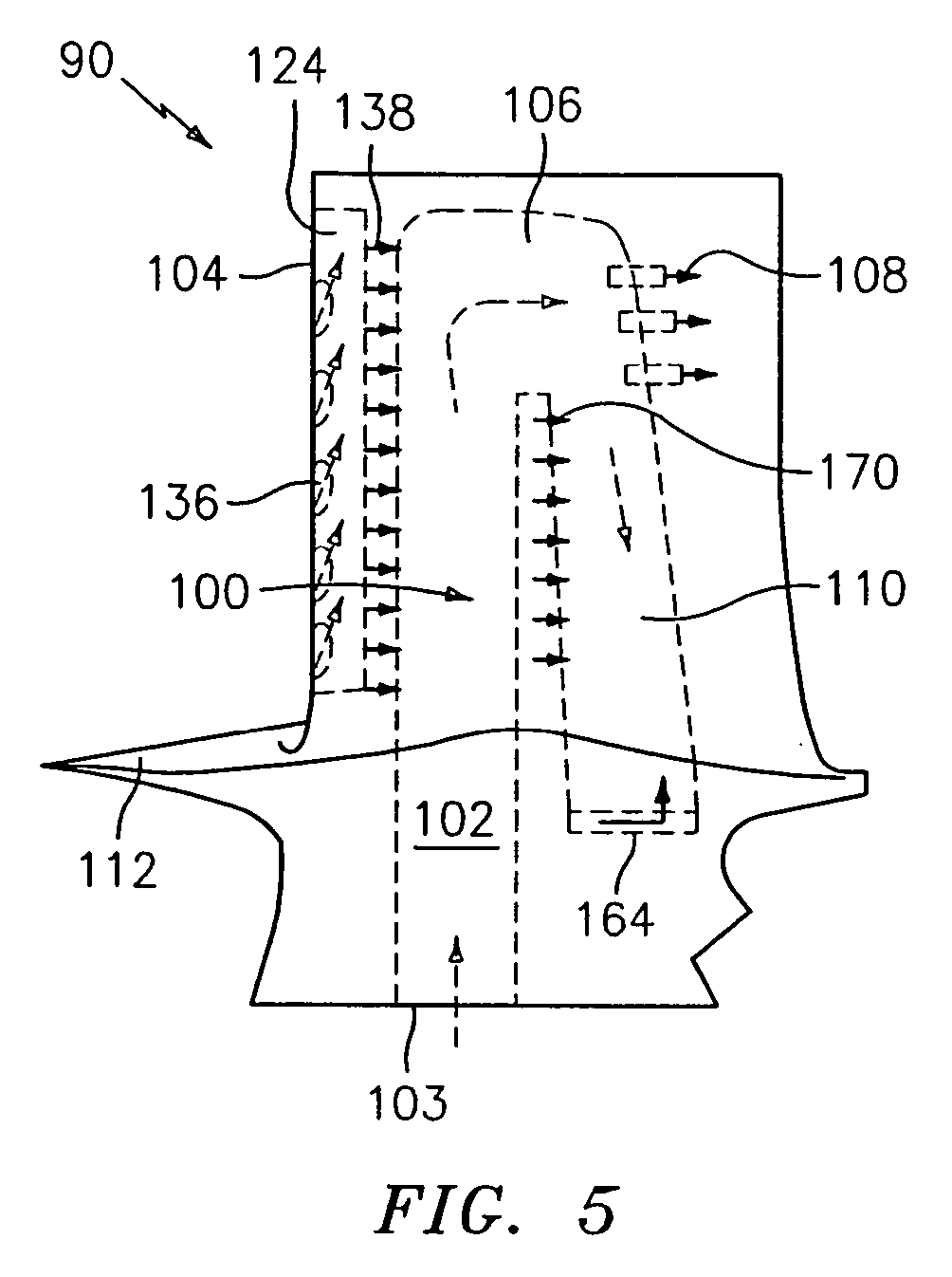
- FIG. 5 is a schematic representation of a peripheral pressure side cooling circuit;
- FIG. 6 is a schematic representation of a peripheral suction side cooling circuit; and
- FIG. 7 is a schematic representation of main body internal cooling circuits.
- Referring now to FIGS. 5 and 6, there are depicted two peripheral cooling arrangements which may be used to address local increases in the airfoil thermal load of a
turbine engine component 90 such as a turbine blade. The two peripheral cooling arrangements include a peripheralpressure side microcircuit 100 which may be incorporated or embedded within the wall forming the pressure side of anairfoil portion 104 and asuction side microcircuit 120 which may be incorporated or embedded within the wall forming the suction side of theairfoil portion 104. - In FIG. 5, the pressure side
peripheral microcircuit 100 is shown. In this circuit, thefirst leg 102 has aninlet 103 which receives cooling fluid from a source (not shown). Theleg 102 provides a flow of cooling fluid which quenches the hot spot in the tip-to-mid region of theairfoil portion 104 shown in FIG. 4B. The cooling fluid within theleg 102 proceeds around a 180degree bend 106 which is supplemented with a plurality of film holes 108, preferably three film holes. The film holes 108 ensure flow acceleration through thebend 106 to a seconddownstream leg 110 which ends below theplatform 112 of theturbine engine component 90 in anexit 164. Cooling fluid from theleg 110 is fed into an internaltrailing edge circuit 114 to be discussed hereinafter via theexit 164 where it is used to further cool theairfoil portion 104. - Referring now to FIG. 6, there is shown a peripheral
suction side microcircuit 120. Thecircuit 120 has afirst leg 122 which communicates with a source (not shown) of cooling fluid. In thefirst leg 122, the cooling flow convects heat away from the suction side. Since thecircuit 120 has no film holes, effective cooling may not be done past the external gage point of theairfoil portion 104 where any film cooling would provide high aerodynamic penalties due to mixing. Thus, thecircuit 120 is used to feed cooling fluid to aleading edge microcircuit 124 which wraps around the leading edge 126 of theairfoil portion 104. Thecircuit 120 feeds or supplies cooling fluid to the leading edge wrap aroundcircuit 124 through a plurality of wall cross over holes 128. As can be seen from FIG. 6, thecircuit 120 has abend 130 and asecond leg 132. Theholes 128 are preferably located in the vicinity of thebend 130 and thesecond leg 132. Thesecond leg 132 may also communicate with the wrap aroundcircuit 124 via apassageway 134. As themicrocircuit 124 wraps around the leading edge,several holes 136 are located in the leading edge and are used to cool the leading edge of theairfoil portion 104. Further, themicrocircuit 124 is provided with a plurality of film holes 138 for creating a film of cooling fluid over the pressure side of the airfoil portion. - Referring now to FIG. 7, there is shown the main body internal cooling circuits which include a leading edge
internal cooling circuit 150 and the trailing edgeinternal cooling circuit 114. The leading edgeinternal cooling circuit 150 communicates with a source (not shown) of cooling fluid, such as engine bleed air, via aninlet 151 and has one or more film cooling holes 152 adjacent thetip 154 of theairfoil portion 104 to provide tip cooling. Thecircuit 150 also has a plurality ofcross-over holes 156 for supplying cooling fluid to theleading edge microcircuit 124. - The trailing edge
internal circuit 114 also communicates with a source (not shown) of cooling fluid, such as engine bleed air, via aninlet 157 and has one or more film cooling holes 158 adjacent thetip 154 to provide tip cooling. Thecircuit 114 also has a plurality ofcross-over holes 160 for communicating with a trailingedge cooling circuit 162 for cooling the trailing edge of theairfoil portion 104. As can be seen from FIG. 7, the trailing edgeinternal circuit 114 also receives cooling fluid from the peripheralpressure side microcircuit 100 via theexit 164. - Each of the leading edge
internal circuit 150 and the trailing edgeinternal circuit 114 may be provided with a plurality of film cooling holes 170 and 172 respectively to form cooling films over the pressure and suction sides of theairfoil portion 104. - Using the pressure and suction side cooling circuits of the present invention, the airfoil portion of a turbine engine component may be very effectively convectively cooled. Using the pressure side circuit, the cooling flow is returned to the trailing edge internal circuit for further cooling of the airfoil. Using the suction side circuit, the leading edge of the airfoil is cooled first before discharging in pressure side film. This effective use of coolant allows for positive effects on cycle thermodynamic efficiency, turbine efficiency, rotor inlet temperature impacts, and specific fuel consumption.
Claims (17)
- A turbine engine component (90) comprising:an airfoil portion (104) having a pressure side and a suction side;a first cooling circuit (100) within said pressure side for cooling said pressure side of said airfoil portion (104); anda second cooling circuit (120) within said suction side for cooling said suction side of said airfoil portion (104) and for cooperating with means for creating a cooling film over said pressure side.
- The turbine engine component according to claim 1, wherein said means for creating a cooling film over said pressure side comprises a cooling circuit (124) wrapped around a leading edge (126) of said airfoil portion (104).
- The turbine engine component according to claim 2, further comprising said cooling circuit (124) wrapped around said leading edge (126) having a first set of film holes (138) for cooling said leading edge.
- The turbine engine component according to claim 3 further comprising said cooling circuit (124) wrapped around said leading edge (126) having a second set of film holes (138) for cooling said pressure side of said airfoil portion (104).
- The turbine engine component according to any preceding claim, further comprising a leading edge internal circuit (150) and a trailing edge internal circuit (114).
- The turbine engine component according to claim 5, wherein said first cooling circuit (100) has an exit (164) which delivers cooling fluid to said trailing edge internal circuit (114).
- The turbine engine component according to claim 6, wherein said first cooling circuit (100) has a first leg (102), a second leg (110), and a bend (106) between said first leg (102) and said second leg (110).
- The turbine engine component according to claim 7, wherein said second leg (110) terminates in said exit (164).
- The turbine engine component according to claim 7 or 8, further comprising means for ensuring flow acceleration through the bend (106).
- The turbine engine component according to claim 9, wherein said flow acceleration ensuring means comprises a plurality of holes (108).
- The turbine engine component according to any of claims 5 to 10, wherein each of said internal circuits (150, 114) has a plurality of film holes for creating a flow of cooling fluid over said pressure side and said suction side.
- The turbine engine component according to any of claims 5 to 11, wherein said leading edge internal circuit (150) has a plurality of cross-over holes (156) for supplying fluid to a leading edge cooling circuit (124).
- The turbine engine component according to any of claims 5 to 12, wherein said trailing edge internal circuit (114) has a plurality of cross-over holes (160) for supplying fluid to a trailing edge cooling circuit (162).
- The turbine engine component according to any of claims 5 to 13, wherein each of said leading edge and said trailing edge internal circuits (150, 114) has means for cooling a tip (154) of said airfoil portion (104).
- The turbine engine component according to any preceding claim, wherein said second cooling circuit (120) has a first leg (122), a second leg (132), and a bend (130) between said first leg (120) and said second leg (132).
- The turbine engine component according to claim 15, wherein said second cooling circuit (120) has a plurality of cross-over holes (128) for supplying cooling fluid to said means for creating a cooling film over said pressure side.
- The turbine engine component according to claim 15 or 16, wherein said second leg (132) communicates with said means for creating a cooling film over said pressure side.
Applications Claiming Priority (2)
| Application Number | Priority Date | Filing Date | Title |
|---|---|---|---|
| US11/489,155 US7513744B2 (en) | 2006-07-18 | 2006-07-18 | Microcircuit cooling and tip blowing |
| US11/494,831 US7581928B1 (en) | 2006-07-28 | 2006-07-28 | Serpentine microcircuits for hot gas migration |
Publications (2)
| Publication Number | Publication Date |
|---|---|
| EP1881157A1 true EP1881157A1 (en) | 2008-01-23 |
| EP1881157B1 EP1881157B1 (en) | 2014-02-12 |
Family
ID=38626923
Family Applications (1)
| Application Number | Title | Priority Date | Filing Date |
|---|---|---|---|
| EP20070252841 Active EP1881157B1 (en) | 2006-07-18 | 2007-07-18 | Serpentine microcircuits for local heat removal |
Country Status (1)
| Country | Link |
|---|---|
| EP (1) | EP1881157B1 (en) |
Cited By (2)
| Publication number | Priority date | Publication date | Assignee | Title |
|---|---|---|---|---|
| CN102606221A (en) * | 2011-01-14 | 2012-07-25 | 通用电气公司 | Curved cooling passages for a turbine component |
| EP2752554A1 (en) * | 2013-01-03 | 2014-07-09 | Siemens Aktiengesellschaft | Blade for a turbomachine |
Citations (7)
| Publication number | Priority date | Publication date | Assignee | Title |
|---|---|---|---|---|
| US5813835A (en) | 1991-08-19 | 1998-09-29 | The United States Of America As Represented By The Secretary Of The Air Force | Air-cooled turbine blade |
| EP1091091A2 (en) * | 1999-10-05 | 2001-04-11 | United Technologies Corporation | Method and apparatus for cooling a wall within a gas turbine engine |
| EP1267038A2 (en) | 2001-06-14 | 2002-12-18 | Rolls-Royce Plc | Air cooled aerofoil |
| EP1420142A1 (en) * | 1997-08-07 | 2004-05-19 | United Technologies Corporation | Cooled airfoil for turbine |
| EP1584790A2 (en) | 2004-04-08 | 2005-10-12 | General Electric Company | Impingement cooled turbine airfoil |
| EP1586739A2 (en) * | 2004-04-15 | 2005-10-19 | General Electric Company | Thermal shield for a gas turbine airfoil |
| US20050265837A1 (en) * | 2003-03-12 | 2005-12-01 | George Liang | Vortex cooling of turbine blades |
-
2007
- 2007-07-18 EP EP20070252841 patent/EP1881157B1/en active Active
Patent Citations (7)
| Publication number | Priority date | Publication date | Assignee | Title |
|---|---|---|---|---|
| US5813835A (en) | 1991-08-19 | 1998-09-29 | The United States Of America As Represented By The Secretary Of The Air Force | Air-cooled turbine blade |
| EP1420142A1 (en) * | 1997-08-07 | 2004-05-19 | United Technologies Corporation | Cooled airfoil for turbine |
| EP1091091A2 (en) * | 1999-10-05 | 2001-04-11 | United Technologies Corporation | Method and apparatus for cooling a wall within a gas turbine engine |
| EP1267038A2 (en) | 2001-06-14 | 2002-12-18 | Rolls-Royce Plc | Air cooled aerofoil |
| US20050265837A1 (en) * | 2003-03-12 | 2005-12-01 | George Liang | Vortex cooling of turbine blades |
| EP1584790A2 (en) | 2004-04-08 | 2005-10-12 | General Electric Company | Impingement cooled turbine airfoil |
| EP1586739A2 (en) * | 2004-04-15 | 2005-10-19 | General Electric Company | Thermal shield for a gas turbine airfoil |
Cited By (4)
| Publication number | Priority date | Publication date | Assignee | Title |
|---|---|---|---|---|
| CN102606221A (en) * | 2011-01-14 | 2012-07-25 | 通用电气公司 | Curved cooling passages for a turbine component |
| CN102606221B (en) * | 2011-01-14 | 2015-07-15 | 通用电气公司 | Curved cooling passages for a turbine component |
| EP2752554A1 (en) * | 2013-01-03 | 2014-07-09 | Siemens Aktiengesellschaft | Blade for a turbomachine |
| WO2014106598A1 (en) * | 2013-01-03 | 2014-07-10 | Siemens Aktiengesellschaft | Blade for a turbomachine |
Also Published As
| Publication number | Publication date |
|---|---|
| EP1881157B1 (en) | 2014-02-12 |
Similar Documents
| Publication | Publication Date | Title |
|---|---|---|
| EP1900904B1 (en) | Multi-peripheral serpentine microcircuits for high aspect ratio blades | |
| EP1882816B1 (en) | Radially split serpentine cooling microcircuits | |
| US8011888B1 (en) | Turbine blade with serpentine cooling | |
| US8366394B1 (en) | Turbine blade with tip rail cooling channel | |
| US7717676B2 (en) | High aspect ratio blade main core modifications for peripheral serpentine microcircuits | |
| US7513744B2 (en) | Microcircuit cooling and tip blowing | |
| US8562295B1 (en) | Three piece bonded thin wall cooled blade | |
| US7862299B1 (en) | Two piece hollow turbine blade with serpentine cooling circuits | |
| US8366392B1 (en) | Composite air cooled turbine rotor blade | |
| US7967563B1 (en) | Turbine blade with tip section cooling channel | |
| US6273682B1 (en) | Turbine blade with preferentially-cooled trailing edge pressure wall | |
| US8016564B1 (en) | Turbine blade with leading edge impingement cooling | |
| EP1884621B1 (en) | Serpentine microciruit cooling with pressure side features | |
| WO2014008016A1 (en) | Airfoil cooling arrangement | |
| US8025482B1 (en) | Turbine blade with dual serpentine cooling | |
| US8317474B1 (en) | Turbine blade with near wall cooling | |
| US20190316472A1 (en) | Double wall airfoil cooling configuration for gas turbine engine | |
| US10590779B2 (en) | Double wall turbine gas turbine engine blade cooling configuration | |
| US10648343B2 (en) | Double wall turbine gas turbine engine vane platform cooling configuration with main core resupply | |
| US7950903B1 (en) | Turbine blade with dual serpentine cooling | |
| US10662780B2 (en) | Double wall turbine gas turbine engine vane platform cooling configuration with baffle impingement | |
| US20080008599A1 (en) | Integral main body-tip microcircuits for blades | |
| US7581928B1 (en) | Serpentine microcircuits for hot gas migration | |
| EP1881157B1 (en) | Serpentine microcircuits for local heat removal | |
| US7988417B1 (en) | Air cooled turbine blade |
Legal Events
| Date | Code | Title | Description |
|---|---|---|---|
| PUAI | Public reference made under article 153(3) epc to a published international application that has entered the european phase |
Free format text: ORIGINAL CODE: 0009012 |
|
| AK | Designated contracting states |
Kind code of ref document: A1 Designated state(s): AT BE BG CH CY CZ DE DK EE ES FI FR GB GR HU IE IS IT LI LT LU LV MC MT NL PL PT RO SE SI SK TR |
|
| AX | Request for extension of the european patent |
Extension state: AL BA HR MK YU |
|
| 17P | Request for examination filed |
Effective date: 20080116 |
|
| 17Q | First examination report despatched |
Effective date: 20080229 |
|
| AKX | Designation fees paid |
Designated state(s): DE GB |
|
| GRAP | Despatch of communication of intention to grant a patent |
Free format text: ORIGINAL CODE: EPIDOSNIGR1 |
|
| INTG | Intention to grant announced |
Effective date: 20130823 |
|
| GRAS | Grant fee paid |
Free format text: ORIGINAL CODE: EPIDOSNIGR3 |
|
| GRAA | (expected) grant |
Free format text: ORIGINAL CODE: 0009210 |
|
| AK | Designated contracting states |
Kind code of ref document: B1 Designated state(s): DE GB |
|
| REG | Reference to a national code |
Ref country code: GB Ref legal event code: FG4D |
|
| REG | Reference to a national code |
Ref country code: DE Ref legal event code: R096 Ref document number: 602007035049 Country of ref document: DE Effective date: 20140327 |
|
| REG | Reference to a national code |
Ref country code: DE Ref legal event code: R097 Ref document number: 602007035049 Country of ref document: DE |
|
| PLBE | No opposition filed within time limit |
Free format text: ORIGINAL CODE: 0009261 |
|
| STAA | Information on the status of an ep patent application or granted ep patent |
Free format text: STATUS: NO OPPOSITION FILED WITHIN TIME LIMIT |
|
| 26N | No opposition filed |
Effective date: 20141113 |
|
| REG | Reference to a national code |
Ref country code: DE Ref legal event code: R097 Ref document number: 602007035049 Country of ref document: DE Effective date: 20141113 |
|
| REG | Reference to a national code |
Ref country code: DE Ref legal event code: R082 Ref document number: 602007035049 Country of ref document: DE Representative=s name: SCHMITT-NILSON SCHRAUD WAIBEL WOHLFROM PATENTA, DE |
|
| REG | Reference to a national code |
Ref country code: DE Ref legal event code: R082 Ref document number: 602007035049 Country of ref document: DE Representative=s name: SCHMITT-NILSON SCHRAUD WAIBEL WOHLFROM PATENTA, DE Ref country code: DE Ref legal event code: R081 Ref document number: 602007035049 Country of ref document: DE Owner name: UNITED TECHNOLOGIES CORP. (N.D.GES.D. STAATES , US Free format text: FORMER OWNER: UNITED TECHNOLOGIES CORP., HARTFORD, CONN., US |
|
| PGFP | Annual fee paid to national office [announced via postgrant information from national office to epo] |
Ref country code: DE Payment date: 20200622 Year of fee payment: 14 |
|
| REG | Reference to a national code |
Ref country code: DE Ref legal event code: R119 Ref document number: 602007035049 Country of ref document: DE |
|
| PG25 | Lapsed in a contracting state [announced via postgrant information from national office to epo] |
Ref country code: DE Free format text: LAPSE BECAUSE OF NON-PAYMENT OF DUE FEES Effective date: 20220201 |
|
| PGFP | Annual fee paid to national office [announced via postgrant information from national office to epo] |
Ref country code: GB Payment date: 20250619 Year of fee payment: 19 |
|
| P01 | Opt-out of the competence of the unified patent court (upc) registered |
Free format text: CASE NUMBER: UPC_APP_0018170_1881157/2025 Effective date: 20251218 |