EP1880941A2 - System for joining acoustic cellular panel sections in edge-to-edge relation - Google Patents
System for joining acoustic cellular panel sections in edge-to-edge relation Download PDFInfo
- Publication number
- EP1880941A2 EP1880941A2 EP07010075A EP07010075A EP1880941A2 EP 1880941 A2 EP1880941 A2 EP 1880941A2 EP 07010075 A EP07010075 A EP 07010075A EP 07010075 A EP07010075 A EP 07010075A EP 1880941 A2 EP1880941 A2 EP 1880941A2
- Authority
- EP
- European Patent Office
- Prior art keywords
- edge
- acoustic
- longitudinal
- barrel
- strip
- Prior art date
- Legal status (The legal status is an assumption and is not a legal conclusion. Google has not performed a legal analysis and makes no representation as to the accuracy of the status listed.)
- Granted
Links
- 230000001413 cellular effect Effects 0.000 title claims description 39
- 210000004027 cell Anatomy 0.000 claims description 57
- 238000000034 method Methods 0.000 claims description 19
- 239000000853 adhesive Substances 0.000 claims description 17
- 230000001070 adhesive effect Effects 0.000 claims description 17
- 210000002421 cell wall Anatomy 0.000 claims description 17
- 239000000945 filler Substances 0.000 claims description 15
- 239000000463 material Substances 0.000 claims description 4
- 238000007789 sealing Methods 0.000 claims description 3
- 238000005187 foaming Methods 0.000 description 10
- 229910052782 aluminium Inorganic materials 0.000 description 6
- XAGFODPZIPBFFR-UHFFFAOYSA-N aluminium Chemical compound [Al] XAGFODPZIPBFFR-UHFFFAOYSA-N 0.000 description 6
- 239000004593 Epoxy Substances 0.000 description 4
- PXHVJJICTQNCMI-UHFFFAOYSA-N Nickel Chemical compound [Ni] PXHVJJICTQNCMI-UHFFFAOYSA-N 0.000 description 4
- 238000010521 absorption reaction Methods 0.000 description 4
- 239000002131 composite material Substances 0.000 description 4
- RTAQQCXQSZGOHL-UHFFFAOYSA-N Titanium Chemical compound [Ti] RTAQQCXQSZGOHL-UHFFFAOYSA-N 0.000 description 3
- 229920006332 epoxy adhesive Polymers 0.000 description 3
- 229910052751 metal Inorganic materials 0.000 description 3
- 239000002184 metal Substances 0.000 description 3
- 229910045601 alloy Inorganic materials 0.000 description 2
- 239000000956 alloy Substances 0.000 description 2
- 229910001026 inconel Inorganic materials 0.000 description 2
- 238000012986 modification Methods 0.000 description 2
- 230000004048 modification Effects 0.000 description 2
- 229910052759 nickel Inorganic materials 0.000 description 2
- 239000010936 titanium Substances 0.000 description 2
- 229910052719 titanium Inorganic materials 0.000 description 2
- 230000013011 mating Effects 0.000 description 1
- 239000007769 metal material Substances 0.000 description 1
Images




Classifications
-
- B—PERFORMING OPERATIONS; TRANSPORTING
- B64—AIRCRAFT; AVIATION; COSMONAUTICS
- B64D—EQUIPMENT FOR FITTING IN OR TO AIRCRAFT; FLIGHT SUITS; PARACHUTES; ARRANGEMENT OR MOUNTING OF POWER PLANTS OR PROPULSION TRANSMISSIONS IN AIRCRAFT
- B64D33/00—Arrangement in aircraft of power plant parts or auxiliaries not otherwise provided for
- B64D33/02—Arrangement in aircraft of power plant parts or auxiliaries not otherwise provided for of combustion air intakes
-
- F—MECHANICAL ENGINEERING; LIGHTING; HEATING; WEAPONS; BLASTING
- F02—COMBUSTION ENGINES; HOT-GAS OR COMBUSTION-PRODUCT ENGINE PLANTS
- F02C—GAS-TURBINE PLANTS; AIR INTAKES FOR JET-PROPULSION PLANTS; CONTROLLING FUEL SUPPLY IN AIR-BREATHING JET-PROPULSION PLANTS
- F02C7/00—Features, components parts, details or accessories, not provided for in, or of interest apart form groups F02C1/00 - F02C6/00; Air intakes for jet-propulsion plants
- F02C7/04—Air intakes for gas-turbine plants or jet-propulsion plants
- F02C7/045—Air intakes for gas-turbine plants or jet-propulsion plants having provisions for noise suppression
-
- F—MECHANICAL ENGINEERING; LIGHTING; HEATING; WEAPONS; BLASTING
- F02—COMBUSTION ENGINES; HOT-GAS OR COMBUSTION-PRODUCT ENGINE PLANTS
- F02K—JET-PROPULSION PLANTS
- F02K1/00—Plants characterised by the form or arrangement of the jet pipe or nozzle; Jet pipes or nozzles peculiar thereto
- F02K1/78—Other construction of jet pipes
- F02K1/82—Jet pipe walls, e.g. liners
- F02K1/827—Sound absorbing structures or liners
-
- B—PERFORMING OPERATIONS; TRANSPORTING
- B64—AIRCRAFT; AVIATION; COSMONAUTICS
- B64D—EQUIPMENT FOR FITTING IN OR TO AIRCRAFT; FLIGHT SUITS; PARACHUTES; ARRANGEMENT OR MOUNTING OF POWER PLANTS OR PROPULSION TRANSMISSIONS IN AIRCRAFT
- B64D33/00—Arrangement in aircraft of power plant parts or auxiliaries not otherwise provided for
- B64D33/02—Arrangement in aircraft of power plant parts or auxiliaries not otherwise provided for of combustion air intakes
- B64D2033/0206—Arrangement in aircraft of power plant parts or auxiliaries not otherwise provided for of combustion air intakes comprising noise reduction means, e.g. acoustic liners
-
- F—MECHANICAL ENGINEERING; LIGHTING; HEATING; WEAPONS; BLASTING
- F05—INDEXING SCHEMES RELATING TO ENGINES OR PUMPS IN VARIOUS SUBCLASSES OF CLASSES F01-F04
- F05D—INDEXING SCHEME FOR ASPECTS RELATING TO NON-POSITIVE-DISPLACEMENT MACHINES OR ENGINES, GAS-TURBINES OR JET-PROPULSION PLANTS
- F05D2260/00—Function
- F05D2260/30—Retaining components in desired mutual position
-
- F—MECHANICAL ENGINEERING; LIGHTING; HEATING; WEAPONS; BLASTING
- F05—INDEXING SCHEMES RELATING TO ENGINES OR PUMPS IN VARIOUS SUBCLASSES OF CLASSES F01-F04
- F05D—INDEXING SCHEME FOR ASPECTS RELATING TO NON-POSITIVE-DISPLACEMENT MACHINES OR ENGINES, GAS-TURBINES OR JET-PROPULSION PLANTS
- F05D2260/00—Function
- F05D2260/96—Preventing, counteracting or reducing vibration or noise
-
- Y—GENERAL TAGGING OF NEW TECHNOLOGICAL DEVELOPMENTS; GENERAL TAGGING OF CROSS-SECTIONAL TECHNOLOGIES SPANNING OVER SEVERAL SECTIONS OF THE IPC; TECHNICAL SUBJECTS COVERED BY FORMER USPC CROSS-REFERENCE ART COLLECTIONS [XRACs] AND DIGESTS
- Y02—TECHNOLOGIES OR APPLICATIONS FOR MITIGATION OR ADAPTATION AGAINST CLIMATE CHANGE
- Y02T—CLIMATE CHANGE MITIGATION TECHNOLOGIES RELATED TO TRANSPORTATION
- Y02T50/00—Aeronautics or air transport
- Y02T50/60—Efficient propulsion technologies, e.g. for aircraft
-
- Y—GENERAL TAGGING OF NEW TECHNOLOGICAL DEVELOPMENTS; GENERAL TAGGING OF CROSS-SECTIONAL TECHNOLOGIES SPANNING OVER SEVERAL SECTIONS OF THE IPC; TECHNICAL SUBJECTS COVERED BY FORMER USPC CROSS-REFERENCE ART COLLECTIONS [XRACs] AND DIGESTS
- Y10—TECHNICAL SUBJECTS COVERED BY FORMER USPC
- Y10T—TECHNICAL SUBJECTS COVERED BY FORMER US CLASSIFICATION
- Y10T29/00—Metal working
- Y10T29/49—Method of mechanical manufacture
- Y10T29/49826—Assembling or joining
- Y10T29/49947—Assembling or joining by applying separate fastener
-
- Y—GENERAL TAGGING OF NEW TECHNOLOGICAL DEVELOPMENTS; GENERAL TAGGING OF CROSS-SECTIONAL TECHNOLOGIES SPANNING OVER SEVERAL SECTIONS OF THE IPC; TECHNICAL SUBJECTS COVERED BY FORMER USPC CROSS-REFERENCE ART COLLECTIONS [XRACs] AND DIGESTS
- Y10—TECHNICAL SUBJECTS COVERED BY FORMER USPC
- Y10T—TECHNICAL SUBJECTS COVERED BY FORMER US CLASSIFICATION
- Y10T29/00—Metal working
- Y10T29/49—Method of mechanical manufacture
- Y10T29/49826—Assembling or joining
- Y10T29/49947—Assembling or joining by applying separate fastener
- Y10T29/49963—Threaded fastener
Definitions
- the invention relates to acoustic panels for aircraft, and more particularly relates to a system for joining edges of one or more acoustic panel sections to maximize the effective acoustic area of the panel sections that is available for noise attenuation.
- Sound absorbing panels or liners often are used to form the inner barrels of the inlets of jet engine nacelles to attenuate noise generated by the engine's fan blades.
- Such panels or liners often include an acoustic cellular core disposed between a perforated inner skin, and an imperforate outer skin.
- the perforated inner skin permits sound waves to enter the innermost ends of the open cells of the core, and the imperforate outer skin reflects the sound waves.
- Such an arrangement is known to dissipate sound energy.
- an acoustic inner barrel of a nacelle typically includes a plurality of circumferential acoustic barrel segments or panels. When the segments are joined together along longitudinal seams, they form a complete acoustic inner barrel.
- the adjoining edges of the acoustic cellular cores of the segments have been connected by a foaming adhesive of a type known to persons of ordinary skill in the art.
- the foaming adhesive 10 typically fills partial cells 12 along adjoined cut edges 14, 16 of the acoustic cellular core sections 18, 20.
- the foaming adhesive 10 also can at least partially fill adjacent full cells 26.
- the foaming adhesive 10 also typically blocks at least some openings 22 in the perforated inner skin 24 along the joint.
- the foaming adhesive 10 effectively prevents sound waves from passing through at least some of the openings 22 in the inner skin 24, and also prevents sound waves from entering the blocked and partially blocked cells 12, 26 of the core sections 18, 20.
- the sound attenuation capability of the associated acoustic inner barrel is less than it would be if the openings 22 and cells 12, 26 remained unblocked by the foaming adhesive 10.
- Such a mechanical joint includes an inner plate 30 and an outer plate 32 on opposed sides of a longitudinal joint 34 between first and second portions 36, 38 of an acoustic barrel 40.
- a plurality of fasteners 42 extend thorough the barrel portions 36, 38 and the inner and outer plates 30, 32, and secure the barrel portions 36, 38 together.
- the inner plate 30 necessarily blocks openings in the perforated inner skin 46, and prevents sound waves from entering the underlying cells 44. Therefore, like the foaming adhesive discussed above, the mechanical connection shown in Fig. 2 effectively reduces the available acoustic area of the inner barrel 40 that is available for sound attenuation.
- the invention includes an acoustic barrel for an engine nacelle inlet.
- the acoustic barrel includes a first longitudinal edge defined by a first cellular core portion disposed between a first perforated inner skin portion and a first outer skin portion, and a second longitudinal edge defined by a second cellular core portion disposed between a second perforated inner skin portion and a second outer skin portion.
- a plurality of first edge cells are disposed along the first longitudinal edge, and a plurality of second edge cells are disposed along the second longitudinal edge.
- Each of the first and second edge cells are characterized by a cell wall opening proximate their respective longitudinal edge.
- At least one strip extends along and substantially covers the cell wall openings in the first and second edge cells. The strip is separate from the first inner and outer skin portions.
- At least one plate extends between and along the first and second longitudinal edges, and is attached to the first and second outer skin portions by a plurality of blind fasteners proximate to the first and second longitudinal edges.
- the invention also includes a method of maximizing the available acoustic area of an engine nacelle inner barrel having an acoustic cellular core, a perforated inner skin, an outer skin, and at least one longitudinal seam extending between first and second cut edges of the acoustic cellular core.
- the method includes sealing the first cut edge of the cellular core such that substantially all of the cells along the first cut edge are unobstructed and available for noise attenuation.
- the method further includes sealing the second cut edge of the cellular core such that substantially all of the cells along the second cut edge are unobstructed and available for noise attenuation.
- the method also includes splicing the first and second edges together by attaching at least one plate to the outer skin across the seam with at least one blind fastener on each side of the seam.
- the invention further includes a joint assembly for connecting first and second longitudinal edges of portions of an acoustic barrel having an open cell core, a perforated inner skin, and an outer skin.
- the joint assembly includes at least one strip covering a plurality of openings in walls of cells along the first and second longitudinal edges, the strip being separate from the inner and outer skins.
- a splice plate has a first portion connected to the outer skin proximate to the first longitudinal edge, and a second portion connected to the outer skin proximate to the second longitudinal edge.
- the invention also includes an acoustic inner barrel for an engine nacelle inlet having an acoustic cellular core, an inner skin, an outer skin, and at least one longitudinal seam.
- the barrel includes means for covering openings in cell walls of a plurality of partial cells along the longitudinal seam. The means for covering is separate from the inner and outer skins.
- the barrel further includes means for connecting opposed edges of the barrel along the seam. The means for connecting is configured to leave cells along the longitudinal seam substantially unobstructed.
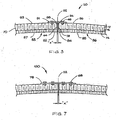
- Fig. 3 shows one embodiment of a joining system 50 according to the invention for joining first and second longitudinal edges 82, 84 of first and second portions 83, 86 of an acoustic barrel 90.
- the acoustic barrel 90 is an inner barrel or liner of an inlet section of a jet engine nacelle.
- the first and second longitudinal edge portions 82, 84 of the first and second barrel portions 83, 86 are arranged in edge-to-edge relation along a seam 92.
- Both the first and second barrel portions 83, 86 include an acoustic cellular core 70.
- the acoustic cellular core 70 has a double-degree-of freedom arrangement of a type known to persons of ordinary skill in the art.
- the core 70 can be of the single-degree-of-freedom type, or a different multiple-degree-of-freedom type (not shown in the figures).
- the core 70 includes an innermost array of cells 74, an outer array of cells 72, and a sound permeable septum 76 therebetween.
- the first and second barrel portions 83, 86 also each include a perforated inner skin 87 on an inside face of the acoustic core 70, and an imperforate outer skin 93.
- the inner skin 87 includes a plurality of spaced openings 23 that permit sound waves to pass through the inner skin 87 to the cells 72, 74 of the acoustic cellular core 70. (See Fig. 5)
- a first plurality of partial edge cells 64 extend along the first longitudinal edge 82, and a second plurality of partial edge cells 58 extend along the second longitudinal edge 84.
- at least some of the edge cells 64, 58 of the acoustic core 70 include openings 65 in their cell walls formed when the edge portions 82, 84 and acoustic cellular core 70 of the first and second barrel portions 83, 86 are cut.
- Edge strips 88, 94 are attached along the longitudinal edges 82, 84, and cover the openings 65 in the cell walls of their respective edges 82, 84.
- the edge strips 88, 94 may be constructed of any suitable and thin material.
- the edge strips 88, 94 are about 0.003 inch to about 0.02 inch thick, though the strips 88, 94 may be thinner or thicker if desired.
- the edge strips 88, 94 can be constructed of a metallic material such as aluminum or titanium foil, a composite material such as graphite-epoxy, or the like.
- the edge strips 88, 94 are adhered to the exposed cell walls along the edges of the cellular core 70 by a non-foaming adhesive.
- the edge strips 88, 94 can be bonded to the cell walls with 3M® Scotch-Weld® Epoxy Adhesive EC-2216 B/A, or another adhesive material having comparable peel and sheer strengths.
- the combined thickness of the edge strips 88, 94 is indicated in Fig. 3 by dimension X.
- X is less than or equal to about 0.12 inch.
- the thin edge strips 88, 94 only occupy an extremely small portion of the inner circumference of the acoustic barrel 90, and thereby maximize the available acoustic area of the barrel 90.
- the edge strips 88, 94 are adhered along the longitudinal edges 82, 84 such that substantially no adhesive fills or partially fills the edge cells 58, 64. Accordingly, the partial edge cells 58, 64 remain substantially open, and thus are available for purposes of sound attenuation.
- a plate 91 is positioned along the seam 92 on the outer skins 93, 96 of the abutted edge portions 82, 84.
- the plate 91 can be constructed of metal, such as aluminum, titanium, or a nickel-based alloy such as Inconel®.
- the plate 91 is constructed of Aluminum 2024, and has a thickness of about 0.09 inch.
- the plate 91 can be constructed of a composite material, such as graphite-epoxy, or the like.
- the plate 91 is connected to the outer skins 93, 96 of the edge portions 82, 84 on each side of the seam 92.
- the plate 91 is connected to the outer skins 93, 96 of the edge portions 82, 84 on each side of the seam 92 by a plurality of blind fasteners 68.
- blind fastener refers to a fastener that can be inserted and tightened without access to the inaccessible or blind side of a mating part.
- the blind fasteners 68 do not obstruct the cells 72, 74 of the acoustic cellular core 70.
- the blind fasteners 68 are blind bolts conforming to either U.S.
- the blind fasteners 68 can be arranged in a single row along each side of the seam 92.
- a wide plate 78 is connected to the outer skins 93, 96 by a plurality of blind fasteners 68 arranged in two rows along each side of the seam 92.
- the size, type, arrangement, and number of blind fasteners 68 that connect the plates 91, 78 to the outer skins 93, 96 can vary depending upon the in-service load conditions experienced by the joints 50, 100.
- the plate 91 can be connected to the outer skins 93, 96 of the edge portions 82, 84 on each side of the seam 92 by a suitable adhesive, such as 3M® Scotch-Weld® Epoxy Adhesive EC-2216 B/A, or the like.
- a suitable adhesive such as 3M® Scotch-Weld® Epoxy Adhesive EC-2216 B/A, or the like.
- the plate 91 can be connected to the outer skins 93, 96 of the edge portions 82, 84 on each side of the seam 92 by a combination of blind fasteners 68 and adhesives.
- substantially all of the surface area of the inner skins 87, 89 on either side of the seam 92 is unaffected by the joining system 50.
- substantially all of the cells 74, 72 of the acoustic cellular core 70 remain unobstructed, and thus available to receive sound waves that enter the cells through openings in the inner skins 87, 89. Accordingly, the joining system 50 maximizes the effective area of the acoustic barrel 90 that is available for the absorption or dissipation of engine noise.
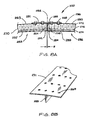
- Fig. 8A shows another embodiment of a joining system 200 according to the invention for joining first and second longitudinal edges 282, 284 of first and second portions 283, 286 of an acoustic barrel 290.
- the first and second longitudinal edge portions 282, 284 of the first and second barrel portions 283, 286 are arranged in edge-to-edge relation along a seam 292.
- Both the first and second barrel portions 283, 286 include an acoustic cellular core 270.
- the acoustic cellular core 270 has a double-degree-of-freedom arrangement of a type known to persons of ordinary skill in the art.
- the core 270 can be of the single-degree-of-freedom type, or a different multiple-degree-of-freedom type (not shown in the figures).
- the core 270 includes an innermost array of cells 274, an outer array of cells 272, and a sound permeable septum 276 therebetween.
- the first and second barrel portions 283, 286 also each include a perforated inner skin 287 on an inside face of the acoustic core 270, and an imperforate outer skin 293.
- the inner skin 287 includes a plurality of spaced openings that permit sound waves to propagate through the inner skin 287 to the cells 272, 274 of the acoustic cellular core 270.
- a first plurality of partial edge cells 264 extend along the first longitudinal edge 282, and a second plurality of partial edge cells 258 extend along the second longitudinal edge 284. At least some of the edge cells 264, 258 of the acoustic core 270 include openings in their cell walls formed when the edge portions 282, 284 and acoustic cellular core 270 of the first and second barrel portions 283, 286 are cut.
- a single filler strip 288 is bonded along the longitudinal edges 282, 284, and covers the openings in the cell walls along both edges.
- the filler strip 288 can be constructed of any suitable and thin material. In one embodiment, the edge strip 288 is about 0.05 inch thick, and is constructed of a metal such as Aluminum 2024.
- the filler strip can be a composite material such as graphite-epoxy, or the like.
- the filler strip 288 is bonded to the exposed cell walls along both edges 282, 284 of the cellular core 270 by a non-foaming adhesive.
- the filler strip 288 can be bonded to the cell walls with 3M® Scotch-Weld® Epoxy Adhesive EC-2216 B/A.
- the total width of the filler strip 288 and the bonding adhesive is indicated in Fig. 8A by dimension Z.
- Z is less than or equal to about 0.2 inch.
- the thin filler strip 288 occupies only and extremely small portion of the inner circumference of the acoustic barrel 290, and thereby maximizes the available acoustic area of the barrel 290. Care is taken during bonding of the filler strip 288 to the longitudinal edges 282, 284 such that substantially no adhesive fills or partially fills the edge cells 258, 264. Thus, the partial edge cells 258, 264 remain substantially open, and thus are available for purposes of sound absorption.
- a plate 291 is positioned along the seam 292 on the outer skins 293, 296 of the abutted edge portions 282, 284.
- the plate 291 can be constructed of metal, such as aluminum, titanium, or a nickel-based alloy such as Inconel®.
- the plate 291 is constructed of Aluminum 2024, and has a thickness of about 0.09 inch.
- the plate 291 can be constructed of a composite material, such as graphite-epoxy, or the like. As shown in Fig.
- the plate is connected to the outer skins 293, 296 of the edge portions 282, 284 on each side of the seam 292 by a plurality of blind fasteners 268, such as MS21141U0603 or MS21141U0604 blind bolts.
- the blind fasteners 268 can be arranged in single or multiple rows along each side of the seam 292. The size, type, arrangement, and number of blind fasteners 268 can vary depending upon the in-service load conditions experienced by the joint 200. As shown in Fig. 8A, substantially all of the surface area of the inner skins 287, 289 on either side of the seam 292 is unaffected by the joining system 200.
- the joining system 200 maximizes the effective area of the acoustic barrel 290 that is available for the absorption or dissipation of engine noise.
- the plate 291 and filler strip 288 shown in Fig. 8A can be constructed as a single unit that provides additional strength and durability to the joint 200.
- a plurality of spaced openings 269 can be provided in the plate 291 for receiving the blind fasteners 268.
- a joining system 50, 100, 200 like that described above can be used to connect longitudinal edge portions of an acoustic barrel along one or more longitudinal seams.
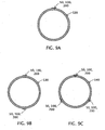
- the joining system 50, 100, 200 is used to join edge portions of a barrel 120 formed in a single piece. Such an arrangement minimizes the number of longitudinal seams, and thereby maximizes the effective acoustic area of the barrel 120.
- a joining system 50, 100, 200 according to the invention also can be used to join longitudinal edges of barrels 130, 140 having two or more separate barrel segments and plural longitudinal seams.
Landscapes
- Engineering & Computer Science (AREA)
- Chemical & Material Sciences (AREA)
- Combustion & Propulsion (AREA)
- Mechanical Engineering (AREA)
- General Engineering & Computer Science (AREA)
- Aviation & Aerospace Engineering (AREA)
- Soundproofing, Sound Blocking, And Sound Damping (AREA)
- Building Environments (AREA)
Abstract
Description
- The invention relates to acoustic panels for aircraft, and more particularly relates to a system for joining edges of one or more acoustic panel sections to maximize the effective acoustic area of the panel sections that is available for noise attenuation.
- Sound absorbing panels or liners often are used to form the inner barrels of the inlets of jet engine nacelles to attenuate noise generated by the engine's fan blades. Such panels or liners often include an acoustic cellular core disposed between a perforated inner skin, and an imperforate outer skin. The perforated inner skin permits sound waves to enter the innermost ends of the open cells of the core, and the imperforate outer skin reflects the sound waves. Such an arrangement is known to dissipate sound energy. Generally, the greater the open area of the perforated inner skin and the greater the number and volume of open cells in the acoustic cellular core available to receive sound waves through the perforated inner skin, the greater the sound attenuation capability of an acoustic inner barrel of a nacelle inlet.
- Typically, an acoustic inner barrel of a nacelle includes a plurality of circumferential acoustic barrel segments or panels. When the segments are joined together along longitudinal seams, they form a complete acoustic inner barrel. Historically, the adjoining edges of the acoustic cellular cores of the segments have been connected by a foaming adhesive of a type known to persons of ordinary skill in the art. As shown in Fig. 1, the foaming adhesive 10 typically fills
partial cells 12 alongadjoined cut edges 14, 16 of the acousticcellular core sections full cells 26. The foaming adhesive 10 also typically blocks at least someopenings 22 in the perforatedinner skin 24 along the joint. Accordingly, the foaming adhesive 10 effectively prevents sound waves from passing through at least some of theopenings 22 in theinner skin 24, and also prevents sound waves from entering the blocked and partially blockedcells core sections openings 22 andcells - Mechanical joints also have been used to connect adjoining edges of acoustic panels. As shown in Fig. 2, such a mechanical joint includes an
inner plate 30 and anouter plate 32 on opposed sides of alongitudinal joint 34 between first andsecond portions acoustic barrel 40. A plurality offasteners 42 extend thorough thebarrel portions outer plates barrel portions inner plate 30 necessarily blocks openings in the perforatedinner skin 46, and prevents sound waves from entering theunderlying cells 44. Therefore, like the foaming adhesive discussed above, the mechanical connection shown in Fig. 2 effectively reduces the available acoustic area of theinner barrel 40 that is available for sound attenuation. - Accordingly, there is a need for a joining method and system for connecting adjoined edges of acoustic cellular panels that minimizes the blockage of openings in the inner skin and of cells proximate to the joint. In addition, there is a need for such a joining method and system that provides a strong and durable connection between the acoustic panels or segments.
- The invention includes an acoustic barrel for an engine nacelle inlet. The acoustic barrel includes a first longitudinal edge defined by a first cellular core portion disposed between a first perforated inner skin portion and a first outer skin portion, and a second longitudinal edge defined by a second cellular core portion disposed between a second perforated inner skin portion and a second outer skin portion. A plurality of first edge cells are disposed along the first longitudinal edge, and a plurality of second edge cells are disposed along the second longitudinal edge. Each of the first and second edge cells are characterized by a cell wall opening proximate their respective longitudinal edge. At least one strip extends along and substantially covers the cell wall openings in the first and second edge cells. The strip is separate from the first inner and outer skin portions. At least one plate extends between and along the first and second longitudinal edges, and is attached to the first and second outer skin portions by a plurality of blind fasteners proximate to the first and second longitudinal edges.
- The invention also includes a method of maximizing the available acoustic area of an engine nacelle inner barrel having an acoustic cellular core, a perforated inner skin, an outer skin, and at least one longitudinal seam extending between first and second cut edges of the acoustic cellular core. The method includes sealing the first cut edge of the cellular core such that substantially all of the cells along the first cut edge are unobstructed and available for noise attenuation. The method further includes sealing the second cut edge of the cellular core such that substantially all of the cells along the second cut edge are unobstructed and available for noise attenuation. The method also includes splicing the first and second edges together by attaching at least one plate to the outer skin across the seam with at least one blind fastener on each side of the seam.
- The invention further includes a joint assembly for connecting first and second longitudinal edges of portions of an acoustic barrel having an open cell core, a perforated inner skin, and an outer skin. The joint assembly includes at least one strip covering a plurality of openings in walls of cells along the first and second longitudinal edges, the strip being separate from the inner and outer skins. A splice plate has a first portion connected to the outer skin proximate to the first longitudinal edge, and a second portion connected to the outer skin proximate to the second longitudinal edge.
- The invention also includes an acoustic inner barrel for an engine nacelle inlet having an acoustic cellular core, an inner skin, an outer skin, and at least one longitudinal seam. The barrel includes means for covering openings in cell walls of a plurality of partial cells along the longitudinal seam. The means for covering is separate from the inner and outer skins. The barrel further includes means for connecting opposed edges of the barrel along the seam. The means for connecting is configured to leave cells along the longitudinal seam substantially unobstructed.
- These and other aspects of the invention will be understood from a reading of the following detailed description together with the drawings.
-
- Fig. 1 is a plan view of a prior art joint that includes a foaming adhesive to connect adjoined edges of acoustic cellular panels.
- Fig. 2 is a cross-sectional view of a prior art mechanical joint for connecting edges of acoustic cellular panels.
- Fig. 3 is a cross-sectional view of one embodiment of a joining method and system according to the invention for connecting edges of acoustic cellular panels.
- Fig. 4 is a perspective view of the joining method and system of Fig. 3 showing the outside face of the joint.
- Fig. 5 is a perspective view of the joining method and system of Figs. 3 and 4 showing the inside face of the joint.
- Fig. 6 is a perspective view of the joining method and system of Figs. 3-5 with portions removed to show hidden details of the joint.
- Fig. 7 is a cross-sectional view of another embodiment of a joining method and system according to the invention.
- Fig. 8A is a cross-sectional view of another embodiment of a joining method and system according to the invention.
- Fig. 8B is a perspective view of a portion of a combined splice plate and filler strip for use in the joining system shown in Fig. 8A.
- Fig. 9A is cross-sectional view of a one-piece acoustic barrel having edges joined by a joining system according to the invention along a single longitudinal seam.
- Fig. 9B is cross-sectional view of a two-piece acoustic barrel having edges joined by joining systems according to the invention along two longitudinal seams.
- Fig. 9C is cross-sectional view of a three-piece acoustic barrel having edges joined by joining systems according to the invention along three longitudinal seams.
- Fig. 3 shows one embodiment of a
joining system 50 according to the invention for joining first and secondlongitudinal edges second portions acoustic barrel 90. In one embodiment, theacoustic barrel 90 is an inner barrel or liner of an inlet section of a jet engine nacelle. The first and secondlongitudinal edge portions second barrel portions seam 92. Both the first andsecond barrel portions cellular core 70. In the embodiment shown, the acousticcellular core 70 has a double-degree-of freedom arrangement of a type known to persons of ordinary skill in the art. Alternatively, the core 70 can be of the single-degree-of-freedom type, or a different multiple-degree-of-freedom type (not shown in the figures). Thecore 70 includes an innermost array ofcells 74, an outer array ofcells 72, and a soundpermeable septum 76 therebetween. The first andsecond barrel portions inner skin 87 on an inside face of theacoustic core 70, and an imperforateouter skin 93. Theinner skin 87 includes a plurality of spacedopenings 23 that permit sound waves to pass through theinner skin 87 to thecells cellular core 70. (See Fig. 5) - As shown in Fig. 3, a first plurality of
partial edge cells 64 extend along the firstlongitudinal edge 82, and a second plurality ofpartial edge cells 58 extend along the secondlongitudinal edge 84. As shown in Fig. 6, at least some of theedge cells acoustic core 70 include openings 65 in their cell walls formed when theedge portions cellular core 70 of the first andsecond barrel portions longitudinal edges respective edges strips cellular core 70 by a non-foaming adhesive. For example, the edge strips 88, 94 can be bonded to the cell walls with 3M® Scotch-Weld® Epoxy Adhesive EC-2216 B/A, or another adhesive material having comparable peel and sheer strengths. The combined thickness of the edge strips 88, 94 is indicated in Fig. 3 by dimension X. Preferably, X is less than or equal to about 0.12 inch. Accordingly, the thin edge strips 88, 94 only occupy an extremely small portion of the inner circumference of theacoustic barrel 90, and thereby maximize the available acoustic area of thebarrel 90. Using methods known to persons of ordinary skill in the art, the edge strips 88, 94 are adhered along thelongitudinal edges edge cells partial edge cells - As shown in Figs. 3, 4 and 6, a
plate 91 is positioned along theseam 92 on theouter skins edge portions plate 91 can be constructed of metal, such as aluminum, titanium, or a nickel-based alloy such as Inconel®. In one embodiment, theplate 91 is constructed of Aluminum 2024, and has a thickness of about 0.09 inch. Alternatively, theplate 91 can be constructed of a composite material, such as graphite-epoxy, or the like. As shown in Fig. 3, theplate 91 is connected to theouter skins edge portions seam 92. Preferably, theplate 91 is connected to theouter skins edge portions seam 92 by a plurality ofblind fasteners 68. As used herein, the term "blind fastener" refers to a fastener that can be inserted and tightened without access to the inaccessible or blind side of a mating part. As can be seen by comparing Fig. 3 to Fig. 2, unlike the through-bolts 42 andinner plate 30 of prior art mechanical joints, theblind fasteners 68 do not obstruct thecells cellular core 70. In one embodiment, theblind fasteners 68 are blind bolts conforming to either U.S. military specification MS21141U0603 or U.S. military specification MS21141U0604. In this embodiment, as shown in Figs. 4 and 6, theblind fasteners 68 can be arranged in a single row along each side of theseam 92. In another embodiment of a joiningsystem 100 according to the invention shown in Fig. 7, awide plate 78 is connected to theouter skins blind fasteners 68 arranged in two rows along each side of theseam 92. The size, type, arrangement, and number ofblind fasteners 68 that connect theplates outer skins joints plate 91 can be connected to theouter skins edge portions seam 92 by a suitable adhesive, such as 3M® Scotch-Weld® Epoxy Adhesive EC-2216 B/A, or the like. In another alternative embodiment, theplate 91 can be connected to theouter skins edge portions seam 92 by a combination ofblind fasteners 68 and adhesives. - As shown in Fig. 5, substantially all of the surface area of the
inner skins seam 92 is unaffected by the joiningsystem 50. In addition, substantially all of thecells cellular core 70 remain unobstructed, and thus available to receive sound waves that enter the cells through openings in theinner skins system 50 maximizes the effective area of theacoustic barrel 90 that is available for the absorption or dissipation of engine noise. - Fig. 8A shows another embodiment of a joining
system 200 according to the invention for joining first and secondlongitudinal edges 282, 284 of first andsecond portions acoustic barrel 290. The first and secondlongitudinal edge portions 282, 284 of the first andsecond barrel portions seam 292. Both the first andsecond barrel portions cellular core 270. In the embodiment shown, the acousticcellular core 270 has a double-degree-of-freedom arrangement of a type known to persons of ordinary skill in the art. Alternatively, thecore 270 can be of the single-degree-of-freedom type, or a different multiple-degree-of-freedom type (not shown in the figures). In the embodiment shown, thecore 270 includes an innermost array ofcells 274, an outer array ofcells 272, and a soundpermeable septum 276 therebetween. The first andsecond barrel portions inner skin 287 on an inside face of theacoustic core 270, and an imperforateouter skin 293. Theinner skin 287 includes a plurality of spaced openings that permit sound waves to propagate through theinner skin 287 to thecells cellular core 270. - As shown in Fig. 8A, a first plurality of
partial edge cells 264 extend along the firstlongitudinal edge 282, and a second plurality ofpartial edge cells 258 extend along the second longitudinal edge 284. At least some of theedge cells acoustic core 270 include openings in their cell walls formed when theedge portions 282, 284 and acousticcellular core 270 of the first andsecond barrel portions single filler strip 288 is bonded along thelongitudinal edges 282, 284, and covers the openings in the cell walls along both edges. Thefiller strip 288 can be constructed of any suitable and thin material. In one embodiment, theedge strip 288 is about 0.05 inch thick, and is constructed of a metal such as Aluminum 2024. Alternatively, the filler strip can be a composite material such as graphite-epoxy, or the like. Thefiller strip 288 is bonded to the exposed cell walls along bothedges 282, 284 of thecellular core 270 by a non-foaming adhesive. For example, thefiller strip 288 can be bonded to the cell walls with 3M® Scotch-Weld® Epoxy Adhesive EC-2216 B/A. The total width of thefiller strip 288 and the bonding adhesive is indicated in Fig. 8A by dimension Z. Preferably, Z is less than or equal to about 0.2 inch. Accordingly, thethin filler strip 288 occupies only and extremely small portion of the inner circumference of theacoustic barrel 290, and thereby maximizes the available acoustic area of thebarrel 290. Care is taken during bonding of thefiller strip 288 to thelongitudinal edges 282, 284 such that substantially no adhesive fills or partially fills theedge cells partial edge cells - As shown in Fig. 8A, a
plate 291 is positioned along theseam 292 on theouter skins edge portions 282, 284. Theplate 291 can be constructed of metal, such as aluminum, titanium, or a nickel-based alloy such as Inconel®. In one embodiment, theplate 291 is constructed of Aluminum 2024, and has a thickness of about 0.09 inch. Alternatively, theplate 291 can be constructed of a composite material, such as graphite-epoxy, or the like. As shown in Fig. 8A, the plate is connected to theouter skins edge portions 282, 284 on each side of theseam 292 by a plurality ofblind fasteners 268, such as MS21141U0603 or MS21141U0604 blind bolts. Theblind fasteners 268 can be arranged in single or multiple rows along each side of theseam 292. The size, type, arrangement, and number ofblind fasteners 268 can vary depending upon the in-service load conditions experienced by the joint 200. As shown in Fig. 8A, substantially all of the surface area of theinner skins seam 292 is unaffected by the joiningsystem 200. In addition, substantially all of thecells cellular core 270 remain open, and thus available to contribute to sound absorption/dissipation. Accordingly, the joiningsystem 200 maximizes the effective area of theacoustic barrel 290 that is available for the absorption or dissipation of engine noise. - As shown in Fig. 8B, the
plate 291 andfiller strip 288 shown in Fig. 8A can be constructed as a single unit that provides additional strength and durability to the joint 200. A plurality of spacedopenings 269 can be provided in theplate 291 for receiving theblind fasteners 268. - As shown in Figs. 9A-9C, a joining
system system barrel 120 formed in a single piece. Such an arrangement minimizes the number of longitudinal seams, and thereby maximizes the effective acoustic area of thebarrel 120. As shown in Figs. 9B and 9C, a joiningsystem barrels - The above description of various embodiments of the invention is intended for purposes of describing different aspects and features of the invention. Persons of ordinary skill in the art will understand that various changes and modifications can be made to the described embodiments without departing from the scope of the invention. All such changes and modifications are intended to be within the scope of the appended claims.
Claims (25)
- An acoustic barrel for an engine nacelle inlet, the acoustic barrel comprising:(a) a first longitudinal edge defined by a first cellular core portion disposed between a first perforated inner skin portion and a first outer skin portion;(b) a second longitudinal edge defined by a second cellular core portion disposed between a second perforated inner skin portion and a second outer skin portion;(c) a plurality of first edge cells along the first longitudinal edge, and a plurality of second edge cells along the second longitudinal edge, each of the first and second edge cells being characterized by a cell wall opening proximate to its respective longitudinal edge;(d) at least one strip substantially covering the cell wall openings in the first and second edge cells, the strip being separate from the first inner and outer skin portions;(e) at least one plate extending between and along the first and second longitudinal edges, the plate being attached to the first and second outer skin portions.
- An acoustic barrel according to claim 1 wherein the strip comprises a first edge strip substantially covering the cell wall openings in the first edge cells, the first edge strip being separate from the first inner and outer skin portions, and a second edge strip substantially covering the cell wall openings in the second edge cells, the second edge strip being separate from the first inner and outer skin portions, wherein the first and second edge strips are substantially parallel, and wherein the combined width of the first second edge strips and the gap is less than or equal to about 0.2 inches wide.
- An acoustic barrel according to claim 1 wherein interior portions of the first and second edge cells are substantially unobstructed.
- An acoustic barrel according to claim 1 wherein the first and second longitudinal edges define a single longitudinal seam in an otherwise continuous barrel.
- An acoustic barrel according to claim 1 wherein the first and second longitudinal edges define a longitudinal seam between first and second barrel segments.
- An acoustic barrel according to claim 1 wherein the at least one plate is attached to the first and second outer skin portions by a plurality of blind fasteners proximate to the first and second longitudinal edges.
- An acoustic barrel according to claim 1 wherein the at least one plate is attached to the first and second outer skin portions by an adhesive material.
- An acoustic barrel according to claim 7 wherein the blind fasteners comprise blind bolts.
- An acoustic barrel according to claim 1 wherein the first and second cellular core portions each include a plurality of cells divided by a perforated septum into first and second cell portions.
- An acoustic barrel according to claim 1 wherein the at least one strip comprises a single filler strip, and an edge of the filler strip is joined to the plate.
- A method of maximizing the available acoustic area of an engine nacelle inner barrel having an acoustic cellular core, a perforated inner skin, an outer skin, and at least one longitudinal seam extending between first and second cut edges of the acoustic cellular core, the method comprising:(a) covering the first cut edge of the cellular core such that substantially all of the cells along the first cut edge remain substantially unobstructed;(b) covering the second cut edge of the cellular core such that substantially all of the cells along the second cut edge remain substantially unobstructed; and(c) splicing the first and second edges together by attaching at least one plate to the outer skin across the seam with at least one blind fastener on each side of the seam.
- A method according to claim 11 and further comprising forming the inner barrel in a single piece having adjoining first and second cut edges defining the longitudinal seam.
- A method according to claim 11 and further comprising forming the inner barrel in at least two segments having adjoining first and second cut edges defining the longitudinal seam.
- A method according to claim 11 wherein sealing either the first or second cut edge of the cellular core includes covering at least a portion of a plurality of openings in cell walls of partial cells along the cut edge with at least one elongated strip that is separate from the inner and outer skins.
- A method according to claim 11 wherein the blind fasteners comprise blind bolts.
- A joint assembly for connecting first and second longitudinal edges of portions of an acoustic barrel having an open cell core, a perforated inner skin, and an outer skin, the joint assembly comprising:(a) at least one strip covering a plurality of openings in walls of cells along the first and second longitudinal edges, the strip being separate from the inner and outer skins; and(b) a splice plate having a first portion connected to the outer skin proximate to the first longitudinal edge, and a second portion connected to the outer skin proximate to the second longitudinal edge.
- A joint assembly according to claim 16, the assembly further comprising a first plurality of blind fasteners connecting the first portion of the splice plate to the outer skin, and a second plurality of blind fasteners connecting the second portion of the splice plate to the outer skin.
- A joint assembly according to claim 17 wherein the blind fasteners comprise blind bolts.
- A joint assembly according to claim 16 wherein the strip comprises a first edge strip covering a plurality of openings in walls of cells along the first longitudinal edge, and a second edge strip covering a plurality of openings in walls of cells along the second longitudinal edge, the first and second edge strips being separate from the inner and outer skins.
- A joint assembly according to claim 16 wherein the strip comprises a single filler strip covering a plurality of openings in walls of cells along both the first and second longitudinal edges, the filler strip being separate from the inner and outer skins.
- A joint assembly according to claim 20 wherein an edge of the filler strip is joined to the splice plate.
- An acoustic inner barrel for an engine nacelle inlet having an acoustic cellular core, an inner skin, an outer skin, and at least one longitudinal seam, the barrel comprising:(a) means for covering openings in cell walls of a plurality of partial cells along the longitudinal seam, the means for covering being separate from the inner and outer skins; and(b) means for connecting opposed edges of the barrel along the seam, the means for connecting being configured to leave sound receiving ends of cells along the longitudinal seam substantially unobstructed.
- An acoustic inner barrel according to claim 22 wherein the means for covering comprises at least one edge strip attached to a longitudinal edge of the acoustic cellular core along the seam.
- An acoustic inner barrel according to claim 22 wherein the means for connecting comprises a plate spanning the seam along the outer skin.
- An acoustic inner barrel according to claim 22 wherein the means for connecting further comprises a plurality of blind fasteners connecting the plate to the outer skin.
Applications Claiming Priority (1)
| Application Number | Priority Date | Filing Date | Title |
|---|---|---|---|
| US11/459,218 US7866440B2 (en) | 2006-07-21 | 2006-07-21 | System for joining acoustic cellular panel sections in edge-to-edge relation |
Publications (3)
| Publication Number | Publication Date |
|---|---|
| EP1880941A2 true EP1880941A2 (en) | 2008-01-23 |
| EP1880941A3 EP1880941A3 (en) | 2011-07-27 |
| EP1880941B1 EP1880941B1 (en) | 2012-09-26 |
Family
ID=38573306
Family Applications (1)
| Application Number | Title | Priority Date | Filing Date |
|---|---|---|---|
| EP07010075A Not-in-force EP1880941B1 (en) | 2006-07-21 | 2007-05-21 | System for joining acoustic cellular panel sections in edge-to-edge relation |
Country Status (2)
| Country | Link |
|---|---|
| US (2) | US7866440B2 (en) |
| EP (1) | EP1880941B1 (en) |
Cited By (9)
| Publication number | Priority date | Publication date | Assignee | Title |
|---|---|---|---|---|
| FR2927952A1 (en) * | 2008-02-27 | 2009-08-28 | Snecma Sa | Quasi-cylindrical sound-insulation wall for turbojet engine nacelle in airplane, has alveolar structure with cylindrical configuration without discontinuity, and carried by another structure formed of juxtaposed sectors fixed end to end |
| EP2186729A1 (en) * | 2008-11-14 | 2010-05-19 | Rohr, Inc. | Acoustic barrel for aircraft engine nacelle including crack and delamination stoppers |
| EP2116695A3 (en) * | 2008-05-06 | 2013-07-03 | Rolls-Royce plc | Fan casing liner panel |
| US9016042B2 (en) | 2011-05-20 | 2015-04-28 | Rohr, Inc. | Reinforcement members for aircraft propulsion system components configured to address delamination of the inner fixed structure |
| EP2362069A3 (en) * | 2010-02-26 | 2017-09-06 | Rolls-Royce plc | Panelled liner assembly of a casing liner in a gas turbine |
| CN108331812A (en) * | 2017-01-18 | 2018-07-27 | 波音公司 | It include the splice of honeycomb core and forming method thereof supported by connection clip |
| EP3372806A1 (en) * | 2017-03-07 | 2018-09-12 | Rolls-Royce Corporation | Acoustic panel of turbine engine and method of arranging the acoustic panel |
| WO2018234710A1 (en) * | 2017-06-23 | 2018-12-27 | Safran Nacelles | ACOUSTIC TREATMENT DEVICE FOR AN AIRCRAFT AIRBORNE NACELLE |
| US20210237890A1 (en) * | 2019-11-07 | 2021-08-05 | Airbus Operations (S.A.S.) | Multifrequency absorption acoustic panel for an aircraft nacelle |
Families Citing this family (30)
| Publication number | Priority date | Publication date | Assignee | Title |
|---|---|---|---|---|
| DE102006026169B4 (en) * | 2006-06-06 | 2012-06-21 | Airbus Operations Gmbh | Aircraft fuselage structure and method for its manufacture |
| DE102006026170B4 (en) * | 2006-06-06 | 2012-06-21 | Airbus Operations Gmbh | Aircraft fuselage structure and method for its manufacture |
| DE102006026168A1 (en) * | 2006-06-06 | 2008-01-31 | Airbus Deutschland Gmbh | Aircraft fuselage structure and method for its manufacture |
| US7866440B2 (en) * | 2006-07-21 | 2011-01-11 | Rohr, Inc. | System for joining acoustic cellular panel sections in edge-to-edge relation |
| FR2905748B1 (en) * | 2006-09-08 | 2011-04-15 | Airbus France | PANEL ASSEMBLY AND MANUFACTURING METHOD |
| FR2926791B1 (en) * | 2008-01-29 | 2010-05-28 | Aircelle Sa | AIR INTAKE FOR AIRCRAFT NACELLE, AND PROPULSIVE ASSEMBLY COMPRISING SUCH AN AIR INTAKE |
| FR2963469B1 (en) * | 2010-07-27 | 2012-07-27 | Aircelle Sa | ACOUSTIC PANEL |
| FR2971613B1 (en) * | 2011-02-10 | 2013-03-15 | Airbus Operations Sas | PANEL FOR ACOUSTIC PROCESSING COMPRISING JOINT BETWEEN TWO PARTS AND METHOD OF REPAIRING A PANEL FOR ACOUSTIC TREATMENT |
| FR2975943B1 (en) * | 2011-06-01 | 2013-05-17 | Aircelle Sa | METHOD FOR MANUFACTURING AN ACOUSTICAL ATTENUATION PANEL |
| DE102011108533A1 (en) * | 2011-07-26 | 2013-01-31 | Rolls-Royce Deutschland Ltd & Co Kg | Exhaust gas turbine cone with three-dimensionally profiled partition and plate-like wall element |
| US8863893B2 (en) * | 2011-11-17 | 2014-10-21 | Spirit Aerosystems, Inc. | Engine inlet varying impedance acoustic liner section |
| FR2984429B1 (en) * | 2011-12-16 | 2014-02-14 | Snecma | VIBRATION DAMPING BANDS WITH FLUID EXHAUST, FOR ACOUSTIC PROTECTION OF AIRCRAFT TURBOMACHINE BLOWER HOUSING |
| EP2620360A1 (en) * | 2012-01-24 | 2013-07-31 | EADS Construcciones Aeronauticas, S.A. | Fire protection device for aircraft |
| US8579076B2 (en) * | 2012-02-29 | 2013-11-12 | Hexcel Corporation | Splicing of curved acoustic honeycomb |
| GB201209658D0 (en) * | 2012-05-31 | 2012-07-11 | Rolls Royce Plc | Acoustic panel |
| GB201313594D0 (en) * | 2013-07-30 | 2013-09-11 | Composite Technology & Applic Ltd | Fan Track Liner |
| WO2015065526A1 (en) * | 2013-10-28 | 2015-05-07 | United Technologies Corporation | Fan case ice liner for turbofan engine |
| US9623621B2 (en) * | 2015-04-03 | 2017-04-18 | The Boeing Company | System and method for securely connecting portions of a composite structure together |
| CN105178823B (en) * | 2015-08-31 | 2017-04-19 | 杭州华为数字技术有限公司 | Noise-reduction door |
| US9708930B2 (en) | 2015-12-09 | 2017-07-18 | Rohr, Inc. | Multi-degree of freedom acoustic panel |
| US10800134B2 (en) | 2016-06-14 | 2020-10-13 | Raytheon Technologies Corporation | Structural panel with woven element core |
| US9779715B1 (en) * | 2016-07-26 | 2017-10-03 | Hexcel Corporation | Method for making contoured acoustic structures |
| US10473030B2 (en) * | 2017-03-07 | 2019-11-12 | Rolls-Royce Corporation | Acoustic panel of turbine engine |
| US10519859B2 (en) * | 2017-03-07 | 2019-12-31 | United Technologies Corporation | Flutter dampening acoustic liner for a turbofan engine |
| FR3086785B1 (en) * | 2018-09-28 | 2022-01-21 | Airbus Operations Sas | ASSEMBLY COMPRISING TWO JUXTAPOSED ACOUSTIC PANELS IN WHICH THE PANELS HAVE A RESISTIVE FACE WHICH EXTENDS TO AN END WALL |
| US11313324B2 (en) * | 2019-04-12 | 2022-04-26 | Rolls-Royce Corporation | Systems and methods of acoustic dampening in a gas turbine engine |
| GB2583751B (en) * | 2019-05-09 | 2022-02-02 | Safran Nacelles Ltd | Acoustic panel |
| US11319833B2 (en) * | 2020-04-24 | 2022-05-03 | General Electric Company | Fan case with crack-arresting backsheet structure and removable containment cartridge |
| CN212899157U (en) * | 2020-07-27 | 2021-04-06 | 开利公司 | Noise reduction device for fan outlet side and heat exchange system comprising same |
| WO2022168761A1 (en) | 2021-02-04 | 2022-08-11 | 出光興産株式会社 | Compound, material for organic electroluminescent element, organic electroluminescent element, and electronic appliance |
Family Cites Families (19)
| Publication number | Priority date | Publication date | Assignee | Title |
|---|---|---|---|---|
| US3579942A (en) * | 1969-12-05 | 1971-05-25 | Thomas & Betts Corp | Fastener anchored in honeycomb panel |
| US4235303A (en) * | 1978-11-20 | 1980-11-25 | The Boeing Company | Combination bulk absorber-honeycomb acoustic panels |
| US4293053A (en) | 1979-12-18 | 1981-10-06 | United Technologies Corporation | Sound absorbing structure |
| US5798778A (en) * | 1992-10-19 | 1998-08-25 | Canon Kabushiki Kaisha | Ink jet head having an ink discharging outlet face and ink jet apparatus provided with said ink jet head |
| DE4340951A1 (en) * | 1992-12-04 | 1994-06-09 | Grumman Aerospace Corp | One-piece engine inlet sound tube |
| US5776579A (en) * | 1996-03-28 | 1998-07-07 | The Boeing Company | Structural bonding with encapsulated foaming adhesive |
| US6017413A (en) * | 1996-10-09 | 2000-01-25 | The Boeing Company | Method and apparatus for honeycomb core splicing |
| FR2767560B1 (en) * | 1997-08-19 | 1999-11-12 | Aerospatiale | NOISE REDUCTION ASSEMBLY FOR AN AIRCRAFT TURBOREACTOR |
| AU4550397A (en) * | 1997-10-09 | 1999-05-03 | Strangaard, Christian | Method of manufacturing a sandwich board and a board and structure manufactured by the method |
| GB9921935D0 (en) * | 1999-09-17 | 1999-11-17 | Rolls Royce | A nacelle assembly for a gas turbine engine |
| FR2840647B1 (en) * | 2002-06-05 | 2004-10-29 | Airbus France | DEVICE FOR CONNECTING TWO TUBULAR PIECES OF AIRCRAFT TURBOREACTOR |
| FR2844304B1 (en) * | 2002-09-10 | 2004-12-10 | Airbus France | ACOUSTICALLY RESISTIVE LAYER FOR ACOUSTIC MITIGATION PANEL, PANEL USING SUCH A LAYER |
| FR2844303B1 (en) * | 2002-09-10 | 2006-05-05 | Airbus France | TUBULAR ACOUSTICAL ATTENUATION PIECE FOR AIRCRAFT REACTOR AIR INTAKE |
| FR2847304B1 (en) * | 2002-11-18 | 2005-07-01 | Airbus France | AIRCRAFT ATTENUATION AIRCRAFT REACTOR NACELLE |
| US6920958B2 (en) * | 2003-10-17 | 2005-07-26 | The Boeing Company | Annular acoustic panel |
| US7328771B2 (en) * | 2004-07-27 | 2008-02-12 | United Technologies Corporation | Zero acoustic splice fan case liner |
| US7296656B2 (en) * | 2005-04-22 | 2007-11-20 | United Technologies Corporation | Acoustic mechanical retainer |
| US7923668B2 (en) * | 2006-02-24 | 2011-04-12 | Rohr, Inc. | Acoustic nacelle inlet lip having composite construction and an integral electric ice protection heater disposed therein |
| US7866440B2 (en) * | 2006-07-21 | 2011-01-11 | Rohr, Inc. | System for joining acoustic cellular panel sections in edge-to-edge relation |
-
2006
- 2006-07-21 US US11/459,218 patent/US7866440B2/en active Active
-
2007
- 2007-05-21 EP EP07010075A patent/EP1880941B1/en not_active Not-in-force
-
2010
- 2010-12-02 US US12/959,156 patent/US8028797B2/en active Active
Non-Patent Citations (1)
| Title |
|---|
| None |
Cited By (16)
| Publication number | Priority date | Publication date | Assignee | Title |
|---|---|---|---|---|
| FR2927952A1 (en) * | 2008-02-27 | 2009-08-28 | Snecma Sa | Quasi-cylindrical sound-insulation wall for turbojet engine nacelle in airplane, has alveolar structure with cylindrical configuration without discontinuity, and carried by another structure formed of juxtaposed sectors fixed end to end |
| EP2116695A3 (en) * | 2008-05-06 | 2013-07-03 | Rolls-Royce plc | Fan casing liner panel |
| US8578697B2 (en) | 2008-05-06 | 2013-11-12 | Rolls-Royce Plc | Fan section |
| EP2186729A1 (en) * | 2008-11-14 | 2010-05-19 | Rohr, Inc. | Acoustic barrel for aircraft engine nacelle including crack and delamination stoppers |
| US7798285B2 (en) | 2008-11-14 | 2010-09-21 | Rohr, Inc. | Acoustic barrel for aircraft engine nacelle including crack and delamination stoppers |
| CN101898639A (en) * | 2008-11-14 | 2010-12-01 | 罗尔股份有限公司 | Acoustic barrel for aircraft engine nacelle including crack and delamination stoppers |
| EP2362069A3 (en) * | 2010-02-26 | 2017-09-06 | Rolls-Royce plc | Panelled liner assembly of a casing liner in a gas turbine |
| US9016042B2 (en) | 2011-05-20 | 2015-04-28 | Rohr, Inc. | Reinforcement members for aircraft propulsion system components configured to address delamination of the inner fixed structure |
| CN108331812A (en) * | 2017-01-18 | 2018-07-27 | 波音公司 | It include the splice of honeycomb core and forming method thereof supported by connection clip |
| EP3372806A1 (en) * | 2017-03-07 | 2018-09-12 | Rolls-Royce Corporation | Acoustic panel of turbine engine and method of arranging the acoustic panel |
| US10612564B2 (en) | 2017-03-07 | 2020-04-07 | Rolls-Royce Corporation | Acoustic panel of turbine engine and method of arranging the acoustic panel |
| WO2018234710A1 (en) * | 2017-06-23 | 2018-12-27 | Safran Nacelles | ACOUSTIC TREATMENT DEVICE FOR AN AIRCRAFT AIRBORNE NACELLE |
| FR3068007A1 (en) * | 2017-06-23 | 2018-12-28 | Safran Nacelles | ACOUSTIC TREATMENT DEVICE FOR AN AIRCRAFT TURBOKARATOR NACELLE |
| US11735153B2 (en) | 2017-06-23 | 2023-08-22 | Safran Nacelles | Acoustic treatment device for an aircraft turbojet engine nacelle |
| US20210237890A1 (en) * | 2019-11-07 | 2021-08-05 | Airbus Operations (S.A.S.) | Multifrequency absorption acoustic panel for an aircraft nacelle |
| US11745887B2 (en) * | 2019-11-07 | 2023-09-05 | Airbus Operations (S.A.S.) | Multifrequency absorption acoustic panel for an aircraft nacelle |
Also Published As
| Publication number | Publication date |
|---|---|
| US20110072637A1 (en) | 2011-03-31 |
| US20080017442A1 (en) | 2008-01-24 |
| US7866440B2 (en) | 2011-01-11 |
| US8028797B2 (en) | 2011-10-04 |
| EP1880941B1 (en) | 2012-09-26 |
| EP1880941A3 (en) | 2011-07-27 |
Similar Documents
| Publication | Publication Date | Title |
|---|---|---|
| EP1880941B1 (en) | System for joining acoustic cellular panel sections in edge-to-edge relation | |
| CA2538806C (en) | Annular acoustic panel | |
| US7798285B2 (en) | Acoustic barrel for aircraft engine nacelle including crack and delamination stoppers | |
| EP1889713B1 (en) | Method of joining composite honeycomb panel sections, and composite panels resulting therefrom | |
| US11686247B2 (en) | Acoustic panel for a nacelle of an aircraft propulsion unit, and related manufacturing methods | |
| US20100108435A1 (en) | Method for making an acoustic absorption panel in particular for the nacelle of an aircraft engine | |
| EP1621752B1 (en) | Noise absorbing liner assembly for a fan case | |
| US20130129483A1 (en) | Crack and delamination stoppers for aircraft propulsion system components | |
| EP3618056B1 (en) | Continuous slanted cell septum | |
| US10273015B2 (en) | Compartmentalized structure for the acoustic treatment and the de-icing of an aircraft nacelle and aircraft nacelle incorporating said structure | |
| CN105501428A (en) | Composite structure having composite-to-metal joints and method for making same | |
| GB2452476A (en) | Acoustic liner for gas turbine engine manufactured by an additive fabrication process | |
| US7296655B2 (en) | Duct liner acoustic splice | |
| CN109763863A (en) | The ring of turbojet blade including Acoustic treatment structure | |
| US11066994B2 (en) | Assembly comprising two juxtaposed acoustic panels in which the panels comprise a resistive face which extends as far as an end wall | |
| CN117730197A (en) | Enhanced acoustic treatment panels for aircraft propulsion units | |
| EP4045410B1 (en) | Aircraft nacelle inlet | |
| EP3966802B1 (en) | Acoustic panel |
Legal Events
| Date | Code | Title | Description |
|---|---|---|---|
| PUAI | Public reference made under article 153(3) epc to a published international application that has entered the european phase |
Free format text: ORIGINAL CODE: 0009012 |
|
| 17P | Request for examination filed |
Effective date: 20070521 |
|
| AK | Designated contracting states |
Kind code of ref document: A2 Designated state(s): AT BE BG CH CY CZ DE DK EE ES FI FR GB GR HU IE IS IT LI LT LU LV MC MT NL PL PT RO SE SI SK TR |
|
| AX | Request for extension of the european patent |
Extension state: AL BA HR MK YU |
|
| PUAL | Search report despatched |
Free format text: ORIGINAL CODE: 0009013 |
|
| AK | Designated contracting states |
Kind code of ref document: A3 Designated state(s): AT BE BG CH CY CZ DE DK EE ES FI FR GB GR HU IE IS IT LI LT LU LV MC MT NL PL PT RO SE SI SK TR |
|
| AX | Request for extension of the european patent |
Extension state: AL BA HR MK RS |
|
| AKX | Designation fees paid |
Designated state(s): AT BE BG CH CY CZ DE DK EE ES FI FR GB GR HU IE IS IT LI LT LU LV MC MT NL PL PT RO SE SI SK TR |
|
| RIC1 | Information provided on ipc code assigned before grant |
Ipc: F02K 1/82 20060101ALI20120301BHEP Ipc: F02C 7/045 20060101ALI20120301BHEP Ipc: B64D 33/02 20060101AFI20120301BHEP |
|
| GRAP | Despatch of communication of intention to grant a patent |
Free format text: ORIGINAL CODE: EPIDOSNIGR1 |
|
| GRAS | Grant fee paid |
Free format text: ORIGINAL CODE: EPIDOSNIGR3 |
|
| GRAA | (expected) grant |
Free format text: ORIGINAL CODE: 0009210 |
|
| AK | Designated contracting states |
Kind code of ref document: B1 Designated state(s): AT BE BG CH CY CZ DE DK EE ES FI FR GB GR HU IE IS IT LI LT LU LV MC MT NL PL PT RO SE SI SK TR |
|
| REG | Reference to a national code |
Ref country code: GB Ref legal event code: FG4D |
|
| REG | Reference to a national code |
Ref country code: CH Ref legal event code: EP |
|
| REG | Reference to a national code |
Ref country code: AT Ref legal event code: REF Ref document number: 576909 Country of ref document: AT Kind code of ref document: T Effective date: 20121015 |
|
| REG | Reference to a national code |
Ref country code: IE Ref legal event code: FG4D |
|
| REG | Reference to a national code |
Ref country code: DE Ref legal event code: R096 Ref document number: 602007025656 Country of ref document: DE Effective date: 20121115 |
|
| PG25 | Lapsed in a contracting state [announced via postgrant information from national office to epo] |
Ref country code: FI Free format text: LAPSE BECAUSE OF FAILURE TO SUBMIT A TRANSLATION OF THE DESCRIPTION OR TO PAY THE FEE WITHIN THE PRESCRIBED TIME-LIMIT Effective date: 20120926 Ref country code: LT Free format text: LAPSE BECAUSE OF FAILURE TO SUBMIT A TRANSLATION OF THE DESCRIPTION OR TO PAY THE FEE WITHIN THE PRESCRIBED TIME-LIMIT Effective date: 20120926 |
|
| REG | Reference to a national code |
Ref country code: AT Ref legal event code: MK05 Ref document number: 576909 Country of ref document: AT Kind code of ref document: T Effective date: 20120926 |
|
| REG | Reference to a national code |
Ref country code: LT Ref legal event code: MG4D Effective date: 20120926 |
|
| REG | Reference to a national code |
Ref country code: NL Ref legal event code: VDEP Effective date: 20120926 |
|
| PG25 | Lapsed in a contracting state [announced via postgrant information from national office to epo] |
Ref country code: GR Free format text: LAPSE BECAUSE OF FAILURE TO SUBMIT A TRANSLATION OF THE DESCRIPTION OR TO PAY THE FEE WITHIN THE PRESCRIBED TIME-LIMIT Effective date: 20121227 Ref country code: SE Free format text: LAPSE BECAUSE OF FAILURE TO SUBMIT A TRANSLATION OF THE DESCRIPTION OR TO PAY THE FEE WITHIN THE PRESCRIBED TIME-LIMIT Effective date: 20120926 Ref country code: LV Free format text: LAPSE BECAUSE OF FAILURE TO SUBMIT A TRANSLATION OF THE DESCRIPTION OR TO PAY THE FEE WITHIN THE PRESCRIBED TIME-LIMIT Effective date: 20120926 Ref country code: SI Free format text: LAPSE BECAUSE OF FAILURE TO SUBMIT A TRANSLATION OF THE DESCRIPTION OR TO PAY THE FEE WITHIN THE PRESCRIBED TIME-LIMIT Effective date: 20120926 |
|
| PG25 | Lapsed in a contracting state [announced via postgrant information from national office to epo] |
Ref country code: RO Free format text: LAPSE BECAUSE OF FAILURE TO SUBMIT A TRANSLATION OF THE DESCRIPTION OR TO PAY THE FEE WITHIN THE PRESCRIBED TIME-LIMIT Effective date: 20120926 Ref country code: CZ Free format text: LAPSE BECAUSE OF FAILURE TO SUBMIT A TRANSLATION OF THE DESCRIPTION OR TO PAY THE FEE WITHIN THE PRESCRIBED TIME-LIMIT Effective date: 20120926 Ref country code: BE Free format text: LAPSE BECAUSE OF FAILURE TO SUBMIT A TRANSLATION OF THE DESCRIPTION OR TO PAY THE FEE WITHIN THE PRESCRIBED TIME-LIMIT Effective date: 20120926 Ref country code: IS Free format text: LAPSE BECAUSE OF FAILURE TO SUBMIT A TRANSLATION OF THE DESCRIPTION OR TO PAY THE FEE WITHIN THE PRESCRIBED TIME-LIMIT Effective date: 20130126 Ref country code: EE Free format text: LAPSE BECAUSE OF FAILURE TO SUBMIT A TRANSLATION OF THE DESCRIPTION OR TO PAY THE FEE WITHIN THE PRESCRIBED TIME-LIMIT Effective date: 20120926 Ref country code: NL Free format text: LAPSE BECAUSE OF FAILURE TO SUBMIT A TRANSLATION OF THE DESCRIPTION OR TO PAY THE FEE WITHIN THE PRESCRIBED TIME-LIMIT Effective date: 20120926 |
|
| PG25 | Lapsed in a contracting state [announced via postgrant information from national office to epo] |
Ref country code: PT Free format text: LAPSE BECAUSE OF FAILURE TO SUBMIT A TRANSLATION OF THE DESCRIPTION OR TO PAY THE FEE WITHIN THE PRESCRIBED TIME-LIMIT Effective date: 20130128 Ref country code: CY Free format text: LAPSE BECAUSE OF FAILURE TO SUBMIT A TRANSLATION OF THE DESCRIPTION OR TO PAY THE FEE WITHIN THE PRESCRIBED TIME-LIMIT Effective date: 20120926 Ref country code: PL Free format text: LAPSE BECAUSE OF FAILURE TO SUBMIT A TRANSLATION OF THE DESCRIPTION OR TO PAY THE FEE WITHIN THE PRESCRIBED TIME-LIMIT Effective date: 20120926 Ref country code: SK Free format text: LAPSE BECAUSE OF FAILURE TO SUBMIT A TRANSLATION OF THE DESCRIPTION OR TO PAY THE FEE WITHIN THE PRESCRIBED TIME-LIMIT Effective date: 20120926 |
|
| PG25 | Lapsed in a contracting state [announced via postgrant information from national office to epo] |
Ref country code: AT Free format text: LAPSE BECAUSE OF FAILURE TO SUBMIT A TRANSLATION OF THE DESCRIPTION OR TO PAY THE FEE WITHIN THE PRESCRIBED TIME-LIMIT Effective date: 20120926 |
|
| PG25 | Lapsed in a contracting state [announced via postgrant information from national office to epo] |
Ref country code: DK Free format text: LAPSE BECAUSE OF FAILURE TO SUBMIT A TRANSLATION OF THE DESCRIPTION OR TO PAY THE FEE WITHIN THE PRESCRIBED TIME-LIMIT Effective date: 20120926 Ref country code: BG Free format text: LAPSE BECAUSE OF FAILURE TO SUBMIT A TRANSLATION OF THE DESCRIPTION OR TO PAY THE FEE WITHIN THE PRESCRIBED TIME-LIMIT Effective date: 20121226 |
|
| PLBE | No opposition filed within time limit |
Free format text: ORIGINAL CODE: 0009261 |
|
| STAA | Information on the status of an ep patent application or granted ep patent |
Free format text: STATUS: NO OPPOSITION FILED WITHIN TIME LIMIT |
|
| PG25 | Lapsed in a contracting state [announced via postgrant information from national office to epo] |
Ref country code: IT Free format text: LAPSE BECAUSE OF FAILURE TO SUBMIT A TRANSLATION OF THE DESCRIPTION OR TO PAY THE FEE WITHIN THE PRESCRIBED TIME-LIMIT Effective date: 20120926 |
|
| 26N | No opposition filed |
Effective date: 20130627 |
|
| REG | Reference to a national code |
Ref country code: DE Ref legal event code: R097 Ref document number: 602007025656 Country of ref document: DE Effective date: 20130627 |
|
| PG25 | Lapsed in a contracting state [announced via postgrant information from national office to epo] |
Ref country code: ES Free format text: LAPSE BECAUSE OF FAILURE TO SUBMIT A TRANSLATION OF THE DESCRIPTION OR TO PAY THE FEE WITHIN THE PRESCRIBED TIME-LIMIT Effective date: 20130106 |
|
| PG25 | Lapsed in a contracting state [announced via postgrant information from national office to epo] |
Ref country code: MC Free format text: LAPSE BECAUSE OF FAILURE TO SUBMIT A TRANSLATION OF THE DESCRIPTION OR TO PAY THE FEE WITHIN THE PRESCRIBED TIME-LIMIT Effective date: 20120926 |
|
| REG | Reference to a national code |
Ref country code: CH Ref legal event code: PL |
|
| PG25 | Lapsed in a contracting state [announced via postgrant information from national office to epo] |
Ref country code: LI Free format text: LAPSE BECAUSE OF NON-PAYMENT OF DUE FEES Effective date: 20130531 Ref country code: CH Free format text: LAPSE BECAUSE OF NON-PAYMENT OF DUE FEES Effective date: 20130531 |
|
| REG | Reference to a national code |
Ref country code: IE Ref legal event code: MM4A |
|
| PG25 | Lapsed in a contracting state [announced via postgrant information from national office to epo] |
Ref country code: IE Free format text: LAPSE BECAUSE OF NON-PAYMENT OF DUE FEES Effective date: 20130521 |
|
| PG25 | Lapsed in a contracting state [announced via postgrant information from national office to epo] |
Ref country code: MT Free format text: LAPSE BECAUSE OF FAILURE TO SUBMIT A TRANSLATION OF THE DESCRIPTION OR TO PAY THE FEE WITHIN THE PRESCRIBED TIME-LIMIT Effective date: 20120926 |
|
| REG | Reference to a national code |
Ref country code: FR Ref legal event code: PLFP Year of fee payment: 9 |
|
| PG25 | Lapsed in a contracting state [announced via postgrant information from national office to epo] |
Ref country code: TR Free format text: LAPSE BECAUSE OF FAILURE TO SUBMIT A TRANSLATION OF THE DESCRIPTION OR TO PAY THE FEE WITHIN THE PRESCRIBED TIME-LIMIT Effective date: 20120926 |
|
| PG25 | Lapsed in a contracting state [announced via postgrant information from national office to epo] |
Ref country code: HU Free format text: LAPSE BECAUSE OF FAILURE TO SUBMIT A TRANSLATION OF THE DESCRIPTION OR TO PAY THE FEE WITHIN THE PRESCRIBED TIME-LIMIT; INVALID AB INITIO Effective date: 20070521 Ref country code: LU Free format text: LAPSE BECAUSE OF NON-PAYMENT OF DUE FEES Effective date: 20130521 |
|
| PGFP | Annual fee paid to national office [announced via postgrant information from national office to epo] |
Ref country code: DE Payment date: 20150422 Year of fee payment: 9 Ref country code: GB Payment date: 20150424 Year of fee payment: 9 |
|
| PGFP | Annual fee paid to national office [announced via postgrant information from national office to epo] |
Ref country code: FR Payment date: 20150422 Year of fee payment: 9 |
|
| REG | Reference to a national code |
Ref country code: DE Ref legal event code: R119 Ref document number: 602007025656 Country of ref document: DE |
|
| GBPC | Gb: european patent ceased through non-payment of renewal fee |
Effective date: 20160521 |
|
| REG | Reference to a national code |
Ref country code: FR Ref legal event code: ST Effective date: 20170131 |
|
| PG25 | Lapsed in a contracting state [announced via postgrant information from national office to epo] |
Ref country code: DE Free format text: LAPSE BECAUSE OF NON-PAYMENT OF DUE FEES Effective date: 20161201 Ref country code: FR Free format text: LAPSE BECAUSE OF NON-PAYMENT OF DUE FEES Effective date: 20160531 |
|
| PG25 | Lapsed in a contracting state [announced via postgrant information from national office to epo] |
Ref country code: GB Free format text: LAPSE BECAUSE OF NON-PAYMENT OF DUE FEES Effective date: 20160521 |