EP1880937A2 - Signal generating apparatus for a bicycle control device - Google Patents
Signal generating apparatus for a bicycle control device Download PDFInfo
- Publication number
- EP1880937A2 EP1880937A2 EP07020634A EP07020634A EP1880937A2 EP 1880937 A2 EP1880937 A2 EP 1880937A2 EP 07020634 A EP07020634 A EP 07020634A EP 07020634 A EP07020634 A EP 07020634A EP 1880937 A2 EP1880937 A2 EP 1880937A2
- Authority
- EP
- European Patent Office
- Prior art keywords
- signal
- input signal
- time interval
- output signal
- upshift
- Prior art date
- Legal status (The legal status is an assumption and is not a legal conclusion. Google has not performed a legal analysis and makes no representation as to the accuracy of the status listed.)
- Granted
Links
Images


Classifications
-
- B—PERFORMING OPERATIONS; TRANSPORTING
- B62—LAND VEHICLES FOR TRAVELLING OTHERWISE THAN ON RAILS
- B62M—RIDER PROPULSION OF WHEELED VEHICLES OR SLEDGES; POWERED PROPULSION OF SLEDGES OR SINGLE-TRACK CYCLES; TRANSMISSIONS SPECIALLY ADAPTED FOR SUCH VEHICLES
- B62M25/00—Actuators for gearing speed-change mechanisms specially adapted for cycles
- B62M25/08—Actuators for gearing speed-change mechanisms specially adapted for cycles with electrical or fluid transmitting systems
Definitions
- the present invention is directed to bicycles and, more particularly, to various features of an apparatus for controlling a bicycle device.
- Bicycle devices that are operated by an electric motor or the like recently have become known.
- the rider may manually operate an electric switch, and the signal produced by the switch may be used to operate a motor that upshifts or downshifts the bicycle transmission accordingly:
- One known bicycle transmission control device includes separate upshift and downshift switches that are separately wired to their corresponding derailleur control units. Such a system increases the amount of hardware that must be mounted to the bicycle.
- Other known bicycle transmissions include a single wire that carries the electrical signals for both upshifting and downshifting the transmission.
- the upshift and downshift signals differ in some way. For example, in an analog system, a +6 volt signal may be used to signal an upshift operation, and a +3 volt signal may be used to signal a downshift operation. Alternatively, a +5 volt signal may be used to signal an upshift operation, and a -5 volt signal may be used to signal a downshift operation.
- a bicycle signal generating apparatus comprises an input unit and a signal generating unit.
- the input unit receives a first input signal and a second input signal, wherein the first input signal corresponds to a first operation of a bicycle device and the second input signal corresponds to a second operation of the bicycle device.
- the signal generating unit generates a first output signal from the first input signal and a second output signal from the second input signal.
- a time interval of the first output signal is based on a time interval of the first input signal, and the first output signal has a transition that occurs within an open interval defined by the time interval of the first input signal.
- a bicycle signal generating apparatus again comprises an input unit and a signal generating unit.
- the input unit receives a first input signal and a second input signal, wherein the first input signal corresponds to a first operation of a bicycle device and the second input signal corresponds to a second operation of the bicycle device.
- the signal generating unit generates a first output signal having a first repeating pattern from the first input signal, and the signal generating unit generates a second output signal having a second repeating pattern from the second input signal.
- the first repeating pattern is different from the second repeating pattern.
- a bicycle signal generating apparatus again comprises an input unit and a signal generating unit.
- the input unit receives a first input signal and a second input signal, wherein the first input signal corresponds to a first operation of a bicycle device and the second input signal corresponds to a second operation of the bicycle device.
- the signal generating unit generates a first output signal including a first pulse from the first input signal and a second output signal including a second pulse from the second input signal. A width of the first pulse is different from a width of the second pulse.
- a bicycle signal generating apparatus again comprises an input unit and a signal generating unit.
- the input unit receives a first input signal and a second input signal, wherein the first input signal corresponds to a first operation of a bicycle device and the second input signal corresponds to a second operation of the bicycle device.
- a time interval of the first input signal is different from a time interval of the second input signal.
- the signal generating unit generates a first output signal from the first input signal and a second output signal from the second input signal.
- a pattern of the first output signal is different from a pattern of the second output signal.
- Fig. 1 is a side view of a bicycle that includes particular embodiments of electrically controlled bicycle transmissions
- Fig. 2 is a detailed view of particular embodiments of handlebar mounted components of the bicycle shown in Fig. 1;
- Fig. 3 is a block diagram of a particular embodiment of a control unit
- Fig. 4A is a timing diagram of an upshift signal provided by a manually operated upshift switch
- Fig. 4B is a timing diagram of an upshift signal provided by a signal generating unit
- Fig. 5A is a timing diagram of a downshift signal provided by a manually operated downshift switch
- Fig. 5B is a timing diagram of a downshift signal provided by the signal generating unit
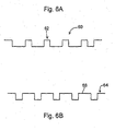
- Fig. 6A is a timing diagram of an alternative embodiment of an upshift signal provided by the signal generating unit
- Fig. 6B is a timing diagram of an alternative embodiment of a downshift signal provided by the signal generating unit
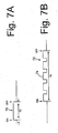
- Fig. 7A is a timing diagram of a single upshift signal provided by the manually operated upshift switch
- Fig. 7B is a timing diagram of a single upshift signal provided by the signal generating unit
- Fig. 8A is a timing diagram of a multiple upshift signal provided by the manually operated upshift switch.
- Fig. 8B is a timing diagram of a multiple upshift signal provided by the signal generating unit.
- Fig. 1 is a side view of a bicycle that includes particular embodiments of electrically controlled bicycle transmissions.
- the bicycle 1 is a sport bicycle of a mountain bike type, and it comprises a frame 2, a front fork 3 rotatably mounted to frame 2, a handlebar assembly 4 mounted to the upper part of front fork 3, a front wheel 5 rotatably attached to the lower part of front fork 3, a rear wheel 6 rotatably attached to the rear of frame 2, a chain 7, a front transmission 8, a rear transmission 9, and a saddle 11.
- a front wheel brake 16 is provided for braking the front wheel 5, and a rear wheel brake 17 is provided for braking the rear wheel 6. As shown in FIG.
- respective grips 12a, 12b and brake levers 13a, 13b are provided on both ends of handlebar assembly 4.
- Brake lever 13b is connected to the front wheel brake 16 for braking front wheel 5
- brake lever 13a is connected to the rear wheel brake 17 for braking rear wheel 6.
- Front transmission 8 is a mechanical unit attached to the central lower part of frame 2 for transmitting drive force generated by the rider to rear transmission 9 via chain 7.
- Front transmission 8 comprises three sprockets 37 of various sizes and a front derailleur 33.
- the three sprockets 37 are installed on a gear crank 31 that rotates when the rider pushes pedals 32a and 32b.
- Gear crank 31 comprises a crankshaft 34 that passes horizontally and rotatably through the central lower part of frame 2, a right crank 35, and a left crank 36.
- One end of right crank 35 is connected to the right side of crankshaft 34
- the three sprockets 37 are attached to right crank 35.
- One end of left crank 36 is connected to the left side of crankshaft 34.
- Front derailleur 33 engages chain 7 with one of the three sprockets 37 and can be moved by a processor-controlled motor (not shown in the figures) that is controlled by a transmission control unit 15 described below.
- a front derailleur position sensor (not shown in the figures) detects the position of front derailleur 33 and hence the current speed step of front transmission 8.
- Rear transmission 9 serves to transmit the driving force transmitted by chain 7 to rear wheel 6.
- Rear transmission 9 comprises a rear sprocket cluster 41 and a rear derailleur 42.
- rear sprocket cluster 41 comprises seven sprockets 43 of different sizes that are mounted concentrically with the hub portion of rear wheel 6.
- Rear derailleur 42 engages chain 7 with one of the seven sprockets 43 and can be moved by a processor-controlled motor (not shown in the figures) that is controlled by transmission control unit 15.
- a rear derailleur position sensor (not shown in the figures) detects the position of rear derailleur 42 and hence the current speed step of rear transmission 9.
- shift command units 14a, 14b are provided inwardly of grips 12a, 12b and brake levers 13a, 13b, respectively.
- Transmission control unit 15 is attached to the central portion of handlebar assembly 4, and it is connected to shift command units 14a, 14b.
- Shift command units 14a, 14b are used for shifting front transmission 8 and rear transmission 9.
- a rear upshift button (switch) 18a and a rear downshift button (switch) 19a are provided in shift command unit 14a
- a front upshift button (switch) 18b and a front downshift button (switch) 19b are provided in shift command unit 14b.
- upshift buttons 18a and 18b provide signals for upshifting front and rear transmissions 8 and 9 by one speed step.
- downshift buttons 19a and 19b provide signals for downshifting front and rear transmissions 8 and 9 by one speed step.
- Transmission control unit 15 controls the operation of front transmission 8 and rear transmission 9 according to the signals provided by shift command units 14a and 14b.
- transmission control unit 15 comprises a control unit 23, a display unit 24 for displaying the current speed step, a power switch 25, and a mode switch 26.
- Control unit 23 includes a CPU 21, a memory 22 and a signal generating unit 29.
- CPU 21 is a programmed processor that operates according to the information stored in memory 22.
- Signal generating unit 29 provides output signals to front derailleur 33 and rear derailleur 42 in response to input signals from shift command units 14a and 14b.
- Power switch 25 turns transmission control unit 15 on and off, and mode switch 26 changes an operating mode of transmission control unit 15.
- transmission control unit 15 includes a box-like housing 27. Display unit 24, power switch 25, and mode switch 26 are arranged on the upper surface of housing 27. Transmission control unit 15 is connected to front transmission 8 and rear transmission 9 by a connector unit 28.
- Fig. 4A is a timing diagram of an upshift signal provided by rear upshift button 18a
- Fig. 4B is a timing diagram of an upshift signal provided by signal generating unit 29 in response to the operation of rear upshift button 18a. Similar signals may be generated in response to the operation of shift command unit 14b.
- pressing rear upshift button 18a for a time interval T1 provides a continuous high first input signal 40 during time interval T1.
- signal generating unit 29 generates a first output signal 44 from first input signal 40, wherein a time interval T2 of first output signal 44 is based on time interval T1 of first input signal 40.
- time interval T1 is the same as time interval T2, but the relationship may change depending upon the application.
- first output signal 40 has a transition (low to high or high to low) that occurs within an open interval defined by the time interval T1 of first input signal 40. In other words, at least one transition occurs sometime during time interval T1 excluding the endpoints of time interval T1.
- first output signal 44 comprises a first pulse 48 that occurs within the open interval, and preferably a plurality of the first pulses 48 that form a first repeating pattern.
- first pulses 48 have high and low pulse widths, each approximately 2 ms in time interval, and the pulse train continues for the entire duration of time interval T2 (e.g., as long as rear upshift button 18a is being pressed).
- Fig. 5A is a timing diagram of a downshift signal provided by rear downshift button 19a
- Fig. 5B is a timing diagram of a downshift signal provided by signal generating unit 29 in response to the operation of rear downshift button 19a.
- pressing rear downshift 19a button for a time interval T3 provides a continuous high second input signal 52 during time interval T3.
- signal generating unit 29 generates a second output signal 54 from second input signal 52, wherein a time interval T4 of second output signal 54 is based on time interval T3 of second input signal 52.
- time interval T3 is the same as time interval T4, but the relationship may change depending upon the application.
- second output signal 54 does not form a pulse within the open interval T3 defined by the time interval of second input signal 52. Instead, second output signal 54 is active low for a plurality of consecutive time intervals T5 (e.g., 2 ms each), thereby forming a repeating (continuous) pattern of low signals for the entire duration of time interval T4 (e.g., as long as rear downshift button 19a is being pressed).
- Fig. 6A is a timing diagram of an alternative embodiment of an upshift (first output) signal 60 provided by signal generating unit 29, and Fig. 6B is a timing diagram of an alternative embodiment of a downshift (second output) signal 64 provided by signal generating unit 29.
- a time interval of upshift signal 60 wherein upshift signal 60 again comprises a plurality of upshift (first) pulses 62, also is based on a time interval of first input signal 40 and form a repeating pattern.
- the high and low pulse widths of upshift signal 60 are not the same. Instead, the high pulse widths are less than the low pulse widths. Of course, the high and low pulse widths may be changed to suit the application.
- downshift signal 64 comprises a plurality of downshift (second) pulses 68 that form a repeating pattern.
- second pulses 68 that form a repeating pattern.
- a plurality of successive pulse widths of the same relative value of downshift signal 64 are different from a plurality of successive pulse widths of the same relative value of upshift signal 60.
- the high pulse widths of downshift signal 64 are greater than the high pulse widths of upshift signal 60
- the low pulse widths of downshift signal 64 are less than the low pulse widths of upshift signal 60.
- the repeating pattern of downshift signal 64 is an inversion of the repeating pattern of upshift signal 60, albeit shifted in phase.
- buttons 18a, 18b, 19a and 19b signals commanding multiple upshifts and/or multiple downshifts may be provided by the appropriate operation of buttons 18a, 18b, 19a and 19b.
- Fig. 7A is a timing diagram of a single upshift signal that may be provided by rear upshift button 18a
- Fig. 7B is a timing diagram of a single upshift signal that may be provided by signal generating unit 29
- Fig. 8A is a timing diagram of a multiple upshift signal that may be provided by rear upshift button 18a
- Fig. 8B is a timing diagram of a multiple upshift signal that may be provided by signal generating unit 29.
- Buttons 18b, 19a and 19b may operate conceptually in the same manner.
- first output signal 72 comprises a plurality of first pulses 74.
- a time interval T7 which is different from (e.g., greater than) time interval T5
- signal generating unit 29 generates a second output signal 78 comprising a plurality of second pulses 80 from second input signal 76 after second input signal 76 turns off, wherein a time interval T8 of second output signal 78 may or may not be based on a time interval T7 of second input signal 76.
- time interval T7 is less than time interval T8, but the relationship may change depending upon the application.
- first output signal 72 has a different pattern than second output signal 78. That way, first output signal 72 can command a single upshift, whereas second output signal 78 can command a multiple upshift (e.g., by two gears).
- second output signal 78 is an inversion of first output signal 72.
- signal generating unit 29 was located within transmission control unit 15, signal generating unit 29 could be placed within shift command units 14a and/or 14b or within some other structure, and control unit 21 may determine the requested operation based on the output signals.
- the signals provided by signal generating unit 29 need not comprise repeating patterns as long as one pattern is distinguishable from the other. While square and rectangular wave pulses were shown, other pulse configurations are possible. While the first and second output signals could be used to control front and rear derailleurs 33 and 42, the teachings herein could be applied to any electrically controlled bicycle device.
Landscapes
- Engineering & Computer Science (AREA)
- Chemical & Material Sciences (AREA)
- Combustion & Propulsion (AREA)
- Transportation (AREA)
- Mechanical Engineering (AREA)
- Steering Devices For Bicycles And Motorcycles (AREA)
- Automatic Cycles, And Cycles In General (AREA)
- Regulating Braking Force (AREA)
- Control Of Transmission Device (AREA)
Abstract


Description
- The present invention is directed to bicycles and, more particularly, to various features of an apparatus for controlling a bicycle device.
- Bicycle devices that are operated by an electric motor or the like recently have become known. For example, the rider may manually operate an electric switch, and the signal produced by the switch may be used to operate a motor that upshifts or downshifts the bicycle transmission accordingly:
- One known bicycle transmission control device includes separate upshift and downshift switches that are separately wired to their corresponding derailleur control units. Such a system increases the amount of hardware that must be mounted to the bicycle. Other known bicycle transmissions include a single wire that carries the electrical signals for both upshifting and downshifting the transmission. In these systems, the upshift and downshift signals differ in some way. For example, in an analog system, a +6 volt signal may be used to signal an upshift operation, and a +3 volt signal may be used to signal a downshift operation. Alternatively, a +5 volt signal may be used to signal an upshift operation, and a -5 volt signal may be used to signal a downshift operation. In a digital system, multibit digital messages that address a particular device and specify the desired operation may be serially communicated on a single wire. In either case, complex calculations must be performed to determine the requested operation with accuracy. In the case of analog systems, the control signals may deteriorate as a result of moisture caused by riding in rain, riding through a puddle, etc.
DocumentEP 1 359 088 discloses a bicycle signal generating apparatus according to the preamble of claim 1. - The present invention is directed to various features of an apparatus for controlling a bicycle device. In one embodiment, a bicycle signal generating apparatus comprises an input unit and a signal generating unit. The input unit receives a first input signal and a second input signal, wherein the first input signal corresponds to a first operation of a bicycle device and the second input signal corresponds to a second operation of the bicycle device. The signal generating unit generates a first output signal from the first input signal and a second output signal from the second input signal. A time interval of the first output signal is based on a time interval of the first input signal, and the first output signal has a transition that occurs within an open interval defined by the time interval of the first input signal.
In another embodiment, not forming part of the present invention, a bicycle signal generating apparatus again comprises an input unit and a signal generating unit. The input unit receives a first input signal and a second input signal, wherein the first input signal corresponds to a first operation of a bicycle device and the second input signal corresponds to a second operation of the bicycle device. The signal generating unit generates a first output signal having a first repeating pattern from the first input signal, and the signal generating unit generates a second output signal having a second repeating pattern from the second input signal. The first repeating pattern is different from the second repeating pattern. - In another embodiment, not forming part of the present invention, a bicycle signal generating apparatus again comprises an input unit and a signal generating unit. The input unit receives a first input signal and a second input signal, wherein the first input signal corresponds to a first operation of a bicycle device and the second input signal corresponds to a second operation of the bicycle device. The signal generating unit generates a first output signal including a first pulse from the first input signal and a second output signal including a second pulse from the second input signal. A width of the first pulse is different from a width of the second pulse.
- In another embodiment, not forming part of the present invention, a bicycle signal generating apparatus again comprises an input unit and a signal generating unit. The input unit receives a first input signal and a second input signal, wherein the first input signal corresponds to a first operation of a bicycle device and the second input signal corresponds to a second operation of the bicycle device. A time interval of the first input signal is different from a time interval of the second input signal. The signal generating unit generates a first output signal from the first input signal and a second output signal from the second input signal. A pattern of the first output signal is different from a pattern of the second output signal.
- Additional inventive features will become apparent from the description below, and such features may be combined with any of the above features alone or in combination to provide additional benefits.
- Fig. 1 is a side view of a bicycle that includes particular embodiments of electrically controlled bicycle transmissions;
- Fig. 2 is a detailed view of particular embodiments of handlebar mounted components of the bicycle shown in Fig. 1;
- Fig. 3 is a block diagram of a particular embodiment of a control unit;
- Fig. 4A is a timing diagram of an upshift signal provided by a manually operated upshift switch;
- Fig. 4B is a timing diagram of an upshift signal provided by a signal generating unit;
- Fig. 5A is a timing diagram of a downshift signal provided by a manually operated downshift switch;
- Fig. 5B is a timing diagram of a downshift signal provided by the signal generating unit;
- Fig. 6A is a timing diagram of an alternative embodiment of an upshift signal provided by the signal generating unit;
- Fig. 6B is a timing diagram of an alternative embodiment of a downshift signal provided by the signal generating unit;
- Fig. 7A is a timing diagram of a single upshift signal provided by the manually operated upshift switch;
- Fig. 7B is a timing diagram of a single upshift signal provided by the signal generating unit;
- Fig. 8A is a timing diagram of a multiple upshift signal provided by the manually operated upshift switch; and
- Fig. 8B is a timing diagram of a multiple upshift signal provided by the signal generating unit.
- Fig. 1 is a side view of a bicycle that includes particular embodiments of electrically controlled bicycle transmissions. The bicycle 1 is a sport bicycle of a mountain bike type, and it comprises a
frame 2, a front fork 3 rotatably mounted toframe 2, a handlebar assembly 4 mounted to the upper part of front fork 3, afront wheel 5 rotatably attached to the lower part of front fork 3, a rear wheel 6 rotatably attached to the rear offrame 2, a chain 7, a front transmission 8, arear transmission 9, and a saddle 11. Afront wheel brake 16 is provided for braking thefront wheel 5, and arear wheel brake 17 is provided for braking the rear wheel 6. As shown in FIG. 2,respective grips 12a, 12b andbrake levers lever 13b is connected to thefront wheel brake 16 for brakingfront wheel 5, andbrake lever 13a is connected to therear wheel brake 17 for braking rear wheel 6. - Front transmission 8 is a mechanical unit attached to the central lower part of
frame 2 for transmitting drive force generated by the rider torear transmission 9 via chain 7. Front transmission 8 comprises threesprockets 37 of various sizes and afront derailleur 33. The threesprockets 37 are installed on a gear crank 31 that rotates when the rider pushespedals 32a and 32b. Gear crank 31 comprises acrankshaft 34 that passes horizontally and rotatably through the central lower part offrame 2, a right crank 35, and aleft crank 36. One end of right crank 35 is connected to the right side ofcrankshaft 34, and the threesprockets 37 are attached to right crank 35. One end of left crank 36 is connected to the left side ofcrankshaft 34. The other ends of right crank 35 and left crank 36rotatably support pedals 32a and 32b, respectively.Front derailleur 33 engages chain 7 with one of the threesprockets 37 and can be moved by a processor-controlled motor (not shown in the figures) that is controlled by atransmission control unit 15 described below. A front derailleur position sensor (not shown in the figures) detects the position offront derailleur 33 and hence the current speed step of front transmission 8. -
Rear transmission 9 serves to transmit the driving force transmitted by chain 7 to rear wheel 6.Rear transmission 9 comprises arear sprocket cluster 41 and arear derailleur 42. In this embodiment,rear sprocket cluster 41 comprises seven sprockets 43 of different sizes that are mounted concentrically with the hub portion of rear wheel 6.Rear derailleur 42 engages chain 7 with one of the seven sprockets 43 and can be moved by a processor-controlled motor (not shown in the figures) that is controlled bytransmission control unit 15. A rear derailleur position sensor (not shown in the figures) detects the position ofrear derailleur 42 and hence the current speed step ofrear transmission 9. - As shown in Fig. 2, shift
command units grips 12a, 12b andbrake levers Transmission control unit 15 is attached to the central portion of handlebar assembly 4, and it is connected to shiftcommand units Shift command units rear transmission 9. A rear upshift button (switch) 18a and a rear downshift button (switch) 19a are provided inshift command unit 14a, and a front upshift button (switch) 18b and a front downshift button (switch) 19b are provided inshift command unit 14b. In this embodiment, upshiftbuttons rear transmissions 8 and 9 by one speed step. Similarly,downshift buttons rear transmissions 8 and 9 by one speed step. -
Transmission control unit 15 controls the operation of front transmission 8 andrear transmission 9 according to the signals provided byshift command units transmission control unit 15, comprises acontrol unit 23, adisplay unit 24 for displaying the current speed step, apower switch 25, and amode switch 26.Control unit 23 includes aCPU 21, amemory 22 and asignal generating unit 29.CPU 21 is a programmed processor that operates according to the information stored inmemory 22. Signal generatingunit 29 provides output signals tofront derailleur 33 andrear derailleur 42 in response to input signals fromshift command units 14a and14b. Power switch 25 turnstransmission control unit 15 on and off, and mode switch 26 changes an operating mode oftransmission control unit 15. As shown in Fig. 2,transmission control unit 15 includes a box-like housing 27.Display unit 24,power switch 25, andmode switch 26 are arranged on the upper surface ofhousing 27.Transmission control unit 15 is connected to front transmission 8 andrear transmission 9 by aconnector unit 28. - Fig. 4A is a timing diagram of an upshift signal provided by
rear upshift button 18a, and Fig. 4B is a timing diagram of an upshift signal provided bysignal generating unit 29 in response to the operation ofrear upshift button 18a. Similar signals may be generated in response to the operation ofshift command unit 14b. As shown in Fig. 4A, pressingrear upshift button 18a for a time interval T1 provides a continuous highfirst input signal 40 during time interval T1. As shown in Fig. 4B,signal generating unit 29 generates afirst output signal 44 fromfirst input signal 40, wherein a time interval T2 offirst output signal 44 is based on time interval T1 offirst input signal 40. In this case, time interval T1 is the same as time interval T2, but the relationship may change depending upon the application. It should be noted thatfirst output signal 40 has a transition (low to high or high to low) that occurs within an open interval defined by the time interval T1 offirst input signal 40. In other words, at least one transition occurs sometime during time interval T1 excluding the endpoints of time interval T1. More specifically,first output signal 44 comprises afirst pulse 48 that occurs within the open interval, and preferably a plurality of thefirst pulses 48 that form a first repeating pattern. In this embodiment,first pulses 48 have high and low pulse widths, each approximately 2 ms in time interval, and the pulse train continues for the entire duration of time interval T2 (e.g., as long asrear upshift button 18a is being pressed). - Fig. 5A is a timing diagram of a downshift signal provided by
rear downshift button 19a, and Fig. 5B is a timing diagram of a downshift signal provided bysignal generating unit 29 in response to the operation ofrear downshift button 19a. As shown in Fig. 5A, pressingrear downshift 19a button for a time interval T3 provides a continuous highsecond input signal 52 during time interval T3. As shown in Fig. 5B,signal generating unit 29 generates asecond output signal 54 fromsecond input signal 52, wherein a time interval T4 ofsecond output signal 54 is based on time interval T3 ofsecond input signal 52. In this case, time interval T3 is the same as time interval T4, but the relationship may change depending upon the application. It should be noted that, in this embodiment, unlikefirst output signal 44,second output signal 54 does not form a pulse within the open interval T3 defined by the time interval ofsecond input signal 52. Instead,second output signal 54 is active low for a plurality of consecutive time intervals T5 (e.g., 2 ms each), thereby forming a repeating (continuous) pattern of low signals for the entire duration of time interval T4 (e.g., as long asrear downshift button 19a is being pressed). - Fig. 6A is a timing diagram of an alternative embodiment of an upshift (first output)
signal 60 provided bysignal generating unit 29, and Fig. 6B is a timing diagram of an alternative embodiment of a downshift (second output)signal 64 provided bysignal generating unit 29. In this embodiment, a time interval ofupshift signal 60, whereinupshift signal 60 again comprises a plurality of upshift (first)pulses 62, also is based on a time interval offirst input signal 40 and form a repeating pattern. However, the high and low pulse widths ofupshift signal 60 are not the same. Instead, the high pulse widths are less than the low pulse widths. Of course, the high and low pulse widths may be changed to suit the application. In this embodiment,downshift signal 64 comprises a plurality of downshift (second)pulses 68 that form a repeating pattern. However, a plurality of successive pulse widths of the same relative value ofdownshift signal 64 are different from a plurality of successive pulse widths of the same relative value ofupshift signal 60. For example, the high pulse widths ofdownshift signal 64 are greater than the high pulse widths ofupshift signal 60, and the low pulse widths ofdownshift signal 64 are less than the low pulse widths ofupshift signal 60. In this embodiment, the repeating pattern ofdownshift signal 64 is an inversion of the repeating pattern ofupshift signal 60, albeit shifted in phase. - While the above is a description of various embodiments of inventive features, further modifications may be employed. For example, while signals commanding single upshifts and single downshifts were provided by the operation of
buttons buttons rear upshift button 18a, and Fig. 7B is a timing diagram of a single upshift signal that may be provided bysignal generating unit 29, whereas Fig. 8A is a timing diagram of a multiple upshift signal that may be provided byrear upshift button 18a, and Fig. 8B is a timing diagram of a multiple upshift signal that may be provided bysignal generating unit 29.Buttons - As shown in Fig. 7A, pressing
rear upshift button 18a for a time interval T5 provides a continuous highfirst input signal 70 during time interval T5. As shown in Fig. 7B,signal generating unit 29 generates afirst output signal 72 fromfirst input signal 70 afterfirst input signal 70 turns off, wherein a time interval T6 offirst output signal 72 may or may not be based on a time interval T5 offirst input signal 70. In this case, time interval T5 is less than time interval T6, but the relationship may change depending upon the application. As in the first embodiment,first output signal 72 comprises a plurality offirst pulses 74. - On the other hand, as shown in Fig. 8A, pressing
rear upshift button 18a for a time interval T7, which is different from (e.g., greater than) time interval T5, provides a continuous highsecond input signal 76 during time interval T7. As shown in Fig. 8B,signal generating unit 29 generates asecond output signal 78 comprising a plurality ofsecond pulses 80 fromsecond input signal 76 aftersecond input signal 76 turns off, wherein a time interval T8 ofsecond output signal 78 may or may not be based on a time interval T7 ofsecond input signal 76. In this case as well, time interval T7 is less than time interval T8, but the relationship may change depending upon the application. In any event,first output signal 72 has a different pattern thansecond output signal 78. That way,first output signal 72 can command a single upshift, whereassecond output signal 78 can command a multiple upshift (e.g., by two gears). In this embodiment,second output signal 78 is an inversion offirst output signal 72. - While
signal generating unit 29 was located withintransmission control unit 15,signal generating unit 29 could be placed withinshift command units 14a and/or 14b or within some other structure, andcontrol unit 21 may determine the requested operation based on the output signals. The signals provided bysignal generating unit 29 need not comprise repeating patterns as long as one pattern is distinguishable from the other. While square and rectangular wave pulses were shown, other pulse configurations are possible. While the first and second output signals could be used to control front andrear derailleurs - The size, shape, location or orientation of the various components may be changed as desired. Components that are shown directly connected or contacting each other may have intermediate structures disposed between them. The functions of one element may be performed by two, and vice versa. The structures and functions of one embodiment may be adopted in another embodiment. It is not necessary for all advantages to be present in a particular embodiment at the same time. Every feature that is unique from the prior art, alone or in combination with other features, also should be considered a separate description of further inventions by the applicant, including the structural and/or functional concepts embodied by such feature(s). Thus, the scope of the invention should not be limited by the specific structures disclosed or the apparent initial focus on a particular structure or feature.
Claims (6)
- A bicycle signal generating apparatus comprising:an input unit that receives a first input signal (40; 70) and a second input signal (52; 76), wherein the first input signal (40; 70) corresponds to a first operation of a bicycle device, and wherein the second input signal (52; 76) corresponds to a second operation of the bicycle device; anda signal generating unit (29);wherein the signal generating unit (29) generates a first output signal (44; 72) from the first input signal (40; 70);
wherein the signal generating unit (29) generates a second output signal (54; 78) from the second input signal (52; 76); characterized in that
a time interval of the first output signal (44; 72) is based on a time interval of the first input signal (40; 70); arid that
the first output signal (44; 72) has a transition that occurs within an open interval defined by the time interval of the first input signal (40; 70). - The apparatus according to claim 1 wherein the first output signal (44; 72) comprises a first pulse that occurs within the open interval.
- The apparatus according to claim 1 or 2 wherein the second output signal (54; 78) does not form a pulse within an open interval defined by the time interval of the second input signal (52; 76).
- The apparatus according to claim 1, 2 or 3 wherein the second output signal (54; 78) comprises a signal having substantially a same value for a plurality of consecutive time intervals.
- The apparatus according to any one of claims 1 to 4 wherein the first output signal (44; 72) comprises a first pulse in particular a plurality of first pulses that occurs within the open interval.
- The apparatus according to claim 5 wherein the plurality of first pulses form a first repeating pattern.
Applications Claiming Priority (2)
| Application Number | Priority Date | Filing Date | Title |
|---|---|---|---|
| US11/161,232 US7522033B2 (en) | 2005-07-27 | 2005-07-27 | Signal generating apparatus for a bicycle control device |
| EP06015593A EP1747987B1 (en) | 2005-07-27 | 2006-07-26 | Signal generating apparatus for a bicycle control device |
Related Parent Applications (2)
| Application Number | Title | Priority Date | Filing Date |
|---|---|---|---|
| EP06015593.4 Division | 2006-07-26 | ||
| EP06015593A Division EP1747987B1 (en) | 2005-07-27 | 2006-07-26 | Signal generating apparatus for a bicycle control device |
Publications (3)
| Publication Number | Publication Date |
|---|---|
| EP1880937A2 true EP1880937A2 (en) | 2008-01-23 |
| EP1880937A3 EP1880937A3 (en) | 2009-02-18 |
| EP1880937B1 EP1880937B1 (en) | 2010-04-28 |
Family
ID=37342446
Family Applications (2)
| Application Number | Title | Priority Date | Filing Date |
|---|---|---|---|
| EP07020634A Not-in-force EP1880937B1 (en) | 2005-07-27 | 2006-07-26 | Signal generating apparatus for a bicycle control device |
| EP06015593A Not-in-force EP1747987B1 (en) | 2005-07-27 | 2006-07-26 | Signal generating apparatus for a bicycle control device |
Family Applications After (1)
| Application Number | Title | Priority Date | Filing Date |
|---|---|---|---|
| EP06015593A Not-in-force EP1747987B1 (en) | 2005-07-27 | 2006-07-26 | Signal generating apparatus for a bicycle control device |
Country Status (5)
| Country | Link |
|---|---|
| US (1) | US7522033B2 (en) |
| EP (2) | EP1880937B1 (en) |
| CN (1) | CN1903654B (en) |
| DE (2) | DE602006003023D1 (en) |
| TW (1) | TWI290114B (en) |
Cited By (1)
| Publication number | Priority date | Publication date | Assignee | Title |
|---|---|---|---|---|
| CN108820126A (en) * | 2017-04-06 | 2018-11-16 | 坎培诺洛有限公司 | Bicycle manual overvide and the bicycle electronic system including it |
Families Citing this family (14)
| Publication number | Priority date | Publication date | Assignee | Title |
|---|---|---|---|---|
| EP2757030B1 (en) | 2008-01-24 | 2015-12-23 | Cycling Sports Group, Inc. | Bicycle user interface system and method of operation thereof |
| US20100010709A1 (en) * | 2008-01-24 | 2010-01-14 | Cannondale Bicycle Corporation | Bicycle distributed computing arrangement and method of operation |
| US7900946B2 (en) * | 2009-03-31 | 2011-03-08 | Shimano Inc. | Bicycle shifting control apparatus |
| US8655561B2 (en) | 2010-06-23 | 2014-02-18 | Shimano Inc. | Bicycle control system having a value generating unit |
| ITMI20121990A1 (en) * | 2012-11-22 | 2014-05-23 | Campagnolo Srl | METHOD OF ELECTRONICALLY CHECKING A BICYCLE CHANGE AND ELECTRICALLY ASSISTED BICYCLE CHANGE |
| US9191038B2 (en) * | 2013-12-24 | 2015-11-17 | Shimano Inc. | Wireless bicycle communication apparatus and wireless bicycle communication system |
| US10046826B2 (en) * | 2015-08-27 | 2018-08-14 | Tektro Technology Corporation | Dual control lever and bicycle control assembly |
| US10829173B2 (en) | 2017-12-21 | 2020-11-10 | Shimano Inc. | Bicycle seatpost assembly |
| US11518470B2 (en) * | 2018-04-30 | 2022-12-06 | Accelerated Systems Inc. | Method and apparatus for controlling a vehicle |
| US11597470B2 (en) | 2018-07-09 | 2023-03-07 | Shimano Inc. | Human-powered vehicle component, mobile electronic device, and equipment for human-powered vehicle |
| US11527980B2 (en) | 2018-07-09 | 2022-12-13 | Shimano Inc. | Electronic device and human-powered vehicle system |
| US11731723B2 (en) | 2018-07-09 | 2023-08-22 | Shimano Inc. | Rider recognition device for human-powered vehicle and control system of human-powered vehicle |
| US11527981B2 (en) * | 2018-07-09 | 2022-12-13 | Shimano Inc. | Human-powered vehicle control device, electronic device, and human-powered vehicle control system |
| TWI697431B (en) * | 2019-05-08 | 2020-07-01 | 彥豪金屬工業股份有限公司 | Bicycle head |
Citations (1)
| Publication number | Priority date | Publication date | Assignee | Title |
|---|---|---|---|---|
| EP1359088A2 (en) | 2002-05-02 | 2003-11-05 | Shimano Inc. | Method and apparatus for controlling a bicycle transmission |
Family Cites Families (13)
| Publication number | Priority date | Publication date | Assignee | Title |
|---|---|---|---|---|
| US4490137A (en) * | 1982-09-30 | 1984-12-25 | Moukheibir Nabil W | Surgically implantable peritoneal dialysis apparatus |
| JPH0620195B2 (en) | 1985-12-06 | 1994-03-16 | 日本電気株式会社 | Speed conversion circuit |
| DE4212320A1 (en) | 1992-04-13 | 1993-10-14 | Fichtel & Sachs Ag | Electric actuator |
| DE4212319A1 (en) | 1992-04-13 | 1993-10-14 | Fichtel & Sachs Ag | control device |
| US6274299B1 (en) * | 1998-06-25 | 2001-08-14 | Eastman Kodak Company | Method of electronically processing an image from a color negative film element |
| IT1310144B1 (en) | 1999-08-24 | 2002-02-11 | Ferrero Spa | SYSTEM AND PROCEDURE FOR THE CONTROL OF TRANSMISSIONS WITH VARIABLE RATIO |
| JP3566682B2 (en) | 2001-09-21 | 2004-09-15 | 株式会社シマノ | Bicycle shift control device and manual shift control device used therefor |
| JP2003120803A (en) * | 2001-10-17 | 2003-04-23 | Shimano Inc | Automatic gear shifting controller for bicycle and method of the same |
| US6741045B2 (en) | 2002-04-23 | 2004-05-25 | Shimano, Inc. | Bicycle control apparatus that communicates power and data over a single transmission path |
| US7116008B2 (en) * | 2002-04-23 | 2006-10-03 | Shimano, Inc. | Electrical communication system for a bicycle |
| US6724299B2 (en) | 2002-06-27 | 2004-04-20 | Shimano, Inc. | Bicycle data communication method and apparatus |
| JP3770390B2 (en) * | 2002-09-19 | 2006-04-26 | 株式会社シマノ | Bicycle shift control device |
| JP2005104286A (en) * | 2003-09-30 | 2005-04-21 | Shimano Inc | Electronic control device for bicycle |
-
2005
- 2005-07-27 US US11/161,232 patent/US7522033B2/en not_active Expired - Fee Related
-
2006
- 2006-03-28 TW TW095110779A patent/TWI290114B/en active
- 2006-07-26 DE DE602006003023T patent/DE602006003023D1/en active Active
- 2006-07-26 EP EP07020634A patent/EP1880937B1/en not_active Not-in-force
- 2006-07-26 EP EP06015593A patent/EP1747987B1/en not_active Not-in-force
- 2006-07-26 DE DE602006013963T patent/DE602006013963D1/en active Active
- 2006-07-27 CN CN2006101075585A patent/CN1903654B/en not_active Expired - Fee Related
Patent Citations (1)
| Publication number | Priority date | Publication date | Assignee | Title |
|---|---|---|---|---|
| EP1359088A2 (en) | 2002-05-02 | 2003-11-05 | Shimano Inc. | Method and apparatus for controlling a bicycle transmission |
Cited By (1)
| Publication number | Priority date | Publication date | Assignee | Title |
|---|---|---|---|---|
| CN108820126A (en) * | 2017-04-06 | 2018-11-16 | 坎培诺洛有限公司 | Bicycle manual overvide and the bicycle electronic system including it |
Also Published As
| Publication number | Publication date |
|---|---|
| EP1880937B1 (en) | 2010-04-28 |
| DE602006013963D1 (en) | 2010-06-10 |
| CN1903654A (en) | 2007-01-31 |
| DE602006003023D1 (en) | 2008-11-20 |
| TW200704563A (en) | 2007-02-01 |
| EP1747987A2 (en) | 2007-01-31 |
| TWI290114B (en) | 2007-11-21 |
| EP1747987B1 (en) | 2008-10-08 |
| US7522033B2 (en) | 2009-04-21 |
| EP1880937A3 (en) | 2009-02-18 |
| EP1747987A3 (en) | 2007-08-22 |
| US20070024435A1 (en) | 2007-02-01 |
| CN1903654B (en) | 2010-08-04 |
Similar Documents
| Publication | Publication Date | Title |
|---|---|---|
| EP1747987B1 (en) | Signal generating apparatus for a bicycle control device | |
| US8475305B2 (en) | Method and apparatus for shifting a bicycle transmission | |
| US8882122B2 (en) | Bicycle gear changing apparatus | |
| US7614971B2 (en) | Apparatus for fine tuning a bicycle derailleur position | |
| US9469377B2 (en) | Bicycle gear changing apparatus | |
| US7730803B2 (en) | Switch designation apparatus for a bicycle control unit | |
| US8998756B2 (en) | Apparatus for adjusting a position of a bicycle derailleur | |
| CN100347038C (en) | Automatic shifting controller for bicycle | |
| EP2808241B1 (en) | Bicycle shifting control apparatus | |
| JP2003327191A (en) | Shift timing decision device | |
| US6725143B2 (en) | Method and apparatus for controlling a bicycle transmission |
Legal Events
| Date | Code | Title | Description |
|---|---|---|---|
| PUAI | Public reference made under article 153(3) epc to a published international application that has entered the european phase |
Free format text: ORIGINAL CODE: 0009012 |
|
| AC | Divisional application: reference to earlier application |
Ref document number: 1747987 Country of ref document: EP Kind code of ref document: P |
|
| AK | Designated contracting states |
Kind code of ref document: A2 Designated state(s): AT BE BG CH CY CZ DE DK EE ES FI FR GB GR HU IE IS IT LI LT LU LV MC NL PL PT RO SE SI SK TR |
|
| AX | Request for extension of the european patent |
Extension state: AL BA HR MK YU |
|
| 17P | Request for examination filed |
Effective date: 20080125 |
|
| RIN1 | Information on inventor provided before grant (corrected) |
Inventor name: SUZUKI, TOSHIKUNIINTRA - SHIMANO, INC. Inventor name: TAKAMOTO, RYUICHIRO Inventor name: KITAMURA, SATOSHI |
|
| PUAL | Search report despatched |
Free format text: ORIGINAL CODE: 0009013 |
|
| AK | Designated contracting states |
Kind code of ref document: A3 Designated state(s): AT BE BG CH CY CZ DE DK EE ES FI FR GB GR HU IE IS IT LI LT LU LV MC NL PL PT RO SE SI SK TR |
|
| AX | Request for extension of the european patent |
Extension state: AL BA HR MK RS |
|
| 17Q | First examination report despatched |
Effective date: 20090416 |
|
| AKX | Designation fees paid |
Designated state(s): DE FR IT |
|
| GRAP | Despatch of communication of intention to grant a patent |
Free format text: ORIGINAL CODE: EPIDOSNIGR1 |
|
| GRAS | Grant fee paid |
Free format text: ORIGINAL CODE: EPIDOSNIGR3 |
|
| GRAA | (expected) grant |
Free format text: ORIGINAL CODE: 0009210 |
|
| AC | Divisional application: reference to earlier application |
Ref document number: 1747987 Country of ref document: EP Kind code of ref document: P |
|
| AK | Designated contracting states |
Kind code of ref document: B1 Designated state(s): DE FR IT |
|
| REF | Corresponds to: |
Ref document number: 602006013963 Country of ref document: DE Date of ref document: 20100610 Kind code of ref document: P |
|
| PLBE | No opposition filed within time limit |
Free format text: ORIGINAL CODE: 0009261 |
|
| STAA | Information on the status of an ep patent application or granted ep patent |
Free format text: STATUS: NO OPPOSITION FILED WITHIN TIME LIMIT |
|
| 26N | No opposition filed |
Effective date: 20110131 |
|
| REG | Reference to a national code |
Ref country code: FR Ref legal event code: PLFP Year of fee payment: 10 |
|
| PGFP | Annual fee paid to national office [announced via postgrant information from national office to epo] |
Ref country code: FR Payment date: 20150629 Year of fee payment: 10 |
|
| PGFP | Annual fee paid to national office [announced via postgrant information from national office to epo] |
Ref country code: IT Payment date: 20160720 Year of fee payment: 11 |
|
| PG25 | Lapsed in a contracting state [announced via postgrant information from national office to epo] |
Ref country code: FR Free format text: LAPSE BECAUSE OF NON-PAYMENT OF DUE FEES Effective date: 20160801 |
|
| REG | Reference to a national code |
Ref country code: FR Ref legal event code: ST Effective date: 20170331 |
|
| PG25 | Lapsed in a contracting state [announced via postgrant information from national office to epo] |
Ref country code: IT Free format text: LAPSE BECAUSE OF NON-PAYMENT OF DUE FEES Effective date: 20170726 |
|
| PGFP | Annual fee paid to national office [announced via postgrant information from national office to epo] |
Ref country code: DE Payment date: 20180710 Year of fee payment: 13 |
|
| REG | Reference to a national code |
Ref country code: DE Ref legal event code: R119 Ref document number: 602006013963 Country of ref document: DE |
|
| PG25 | Lapsed in a contracting state [announced via postgrant information from national office to epo] |
Ref country code: DE Free format text: LAPSE BECAUSE OF NON-PAYMENT OF DUE FEES Effective date: 20200201 |