EP1880905B1 - Bumper with supports - Google Patents
Bumper with supports Download PDFInfo
- Publication number
- EP1880905B1 EP1880905B1 EP20070014123 EP07014123A EP1880905B1 EP 1880905 B1 EP1880905 B1 EP 1880905B1 EP 20070014123 EP20070014123 EP 20070014123 EP 07014123 A EP07014123 A EP 07014123A EP 1880905 B1 EP1880905 B1 EP 1880905B1
- Authority
- EP
- European Patent Office
- Prior art keywords
- bumper
- edge
- support
- slots
- longitudinal
- Prior art date
- Legal status (The legal status is an assumption and is not a legal conclusion. Google has not performed a legal analysis and makes no representation as to the accuracy of the status listed.)
- Not-in-force
Links
Images

Classifications
-
- B—PERFORMING OPERATIONS; TRANSPORTING
- B60—VEHICLES IN GENERAL
- B60R—VEHICLES, VEHICLE FITTINGS, OR VEHICLE PARTS, NOT OTHERWISE PROVIDED FOR
- B60R19/00—Wheel guards; Radiator guards, e.g. grilles; Obstruction removers; Fittings damping bouncing force in collisions
- B60R19/02—Bumpers, i.e. impact receiving or absorbing members for protecting vehicles or fending off blows from other vehicles or objects
- B60R19/24—Arrangements for mounting bumpers on vehicles
- B60R19/26—Arrangements for mounting bumpers on vehicles comprising yieldable mounting means
- B60R19/34—Arrangements for mounting bumpers on vehicles comprising yieldable mounting means destroyed upon impact, e.g. one-shot type
Definitions
- the invention relates to a bumper with - on this to be mounted - projecting from her brackets for attachment to longitudinal members of a vehicle, wherein at the bumper at a distance from each other as a pressure belt or tension belt arranged profile walls and a pair of connecting flank walls form a hollow profile.
- the holder can be configured as at least one side wall and two adjacent thereto transverse walls exhibiting hollow profile with a longitudinal member associated hollow profile support section and the hollow profile of the bumper optionally be curved at least in the region of the brackets relative to a transverse plane of the longitudinal axis of the vehicle.
- a bumper with the longitudinal axis of its longitudinal member crossing plate-like brackets describes the EP 0 718 158 B1 pointing out that in addition to the cross-sectional shape of the bumper and the design of the connection to the vehicle longitudinal beam affects their dimensional stability and their compensation capacity for the incident deformation energy.
- brackets for example US-A-5,080,410 or US-A-4,563,028 - which, however, hardly contribute to the improvement of the dimensional stability of a bumper in an impact.
- the inventor has set the goal, in a bumper of the type mentioned, which has a high degree of dimensional stability with sufficient compensation capacity for the incident deformation energy at low weight, a way to create a stable connection of a bumper to the To allow associated vehicle and to significantly reduce deformation under impact load.
- the bumper's far end of - from a hollow section about rectangular Cross-section existing - holder or its frame-like end edge as a connecting member abut a rear plate, which is preferably welded to the bracket.
- the rear plate From the surface of the rear plate protrudes according to the invention near a longitudinal edge and parallel to a rear plate formed flank web, which rests in the installed position of a side wall outer surface of the posture and thus allows better fixation.
- the rear plate associated longitudinal edge reinforcing - base strip be formed, which has a to the adjacent longitudinal edge of the rear plate inclined surface has a widening to its longitudinal edge cross-section.
- the height of the edge bar corresponds to about half its length.
- the bumper and support unit is provided with compensation elements which limit deformations on the support which are triggered by pressure forces influencing the bumper, for example by the force of a collision.
- the holder is welded at least one end and is equipped near the weld with at least one hole-like wall opening in its wall.
- the described compensation can also be effected by at least one blind slot, which is cut into the edge region of the holder remote from the bumper and inclined to a diametral plane crossing its center line. At the blind slot or at a pair of both sides of the center line and mutually parallel blind slots ends the deformation load.
- Another compensation element should be designed as a rod. This is - similar to the blind slot described above - assigned to the bumper remote edge portion of the holder as a inclined to its center line diametrical plane profile, which protrudes from a lower weld and rests against the surface of the wall. Preference is given to two parallel bars on the outer surface of the wall. In the case of a deformation load also ends their creative force on these rods.
- the holder contains the wall openings and is equipped on its outer surface with those rods.
- Another type of compensation according to the invention is based on an emanating from the front edge of the bumper pair of longitudinal or end slots, each in one of the flank walls in the on the inner or Buchgurt the Bumper adjoining area is arranged.
- the holder is to be connected to the tension belt by a weld so that a part of the wall of this bracket is added below the end slots to the bumper.
- the end slot advantageously overlaps the centerline of the holder, and the end edge of the end slot is adjacent the centerline of the holder. As low, it has been found to choose the length of the end slot shorter than the diameter of the holder.
- these longitudinal or end slots of the bumper may be associated with the wall openings of the holder and / or the end slots extending from the peripheral edge thereof.
- the rods which conform to the outer or surface of the holder can also be used.
- the longitudinal edges of the rear plate should be longer than their transverse edges, and should also be formed on one of the transitions between a transverse edge and a longitudinal edge of the latter a plate portion with a part-circular - preferably a semicircular - outer edge. Its center determines the position of a breakthrough, thanks to which the rear plate can be prefixed to a corresponding counter-member of the longitudinal member.
- openings for connecting members are provided according to a further feature of the invention in the areas of the transitions of the transverse edges to the longitudinal edges - ie also in the other corner areas.
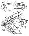
- the bumper 10 is here associated with a pair of vehicle longitudinal members 30, which extend on both sides parallel to the vehicle longitudinal axis A. They are in turn composed of two parallel side walls 34 and these connecting transverse walls 36, the one in Fig. 3 limit recognizable interior 32 of the vehicle longitudinal member 30.
- Fig. 1 In the prior art reproducing right section of Fig. 1 is near the end edge 20 of the hollow section 12 on the right side mounted in the longitudinal member 30 tubular, also made of a extruded from light extruded profile element deformation member 40 indicated as a holder of a profile element at the other end a wedge-shaped in the side support member 43 is fixed.
- Fig. 2 shows - a direction of symmetry axis A directed towards the inclination wall of a holder plate 42 and is screwed in installation position via diagonally arranged holes with the bracket 40 - or the vehicle longitudinal member 30. From the holder plate 42, the wedge-shaped support member 43 is formed to form a cavity.
- FIG. 1 Another embodiment of the connection of the hollow profile 12 to the vehicle side member 30 is at the in Fig. 1 left end of the bumper 10 as well as in Fig. 3 outlined.
- serving as the outer belt in cross-section wavy shaped profile wall 14 both transverse or flank walls 18 with wing-like wall sections as edge strips 15, 15 t overlaps.
- Fig. 3 recognize that the side wall 34 of the Vehicle longitudinal member 30 also with an edge strip 35, the outer surface of the attached transverse wall 36 surmounted.
- the second side wall 34 is not shown here for reasons of clarity and their attachment area highlighted hatched.
- connection of the hollow profile 12 to the vehicle longitudinal member 30 is here by a from a - extruded in turn from an aluminum alloy - as a hollow profile of width b, for example, 55 mm and the height h of 75 mm designed holding member 46.
- an aluminum alloy - as a hollow profile of width b, for example, 55 mm and the height h of 75 mm designed holding member 46.
- At its the vehicle longitudinal member 30 of the profile height e associated and screwed in this plug-in portion 48 approximately rectangular cross-section - of two parallel side walls 49 and connecting transverse walls 50 of the hollow profile of the holder 46 - includes a curvature section 52; in the Fig.
- right side wall 49 is outwardly - so here from the longitudinal axis M 1 of the plug portion 48 to the right - - curved and the other side wall 49 endward to this so introduced that both side walls 49 lie on each other and each of the two transverse walls 50 approximately in its longitudinal center folded.
- the double-layered legs 54 of the trough-like curvature section 52 thus formed are in the range of - not visible in the drawing - breakthroughs of screws 56 or the like. Interspersed through connecting organs, which also engage in bumper-side openings of the flank walls 18. Corresponding openings for connecting members 56 a are provided in the plug portion 48 of the support member 46. These connecting members 56 a store in the vehicle longitudinal member 30 in openings 38th
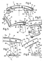
- flank walls 18 and the connecting these profile walls 14, 16 of the bumper 11 in Fig. 4, 5 produce an iw square cross section of a hollow profile 12 a , the corners of which are determined by profile beads 17.
- a profile element 60 tubular shape of the diameter d of a light metal alloy to the tension belt 16 welded to a weld.
- the wall 58 of this profile tube 60 is provided at a small distance f to the tension belt 16 with a pair of wall openings 64, each of which determines an approximately circular edge 66;
- Each wall opening 64 of the deformation member 60 is provided below one of the two lower profile beads 17 of the bumper 11.
- This bottom plate 68 is attached to a partner by screws 56 b .
- two weld seams 62, 62 t are provided, on the lower two of which are arranged on a common diametral D laid through the center line M of the deformation element 60 and inclined at an angle w 1 of approximately 45 ° to the base plate 68, narrow n slots 70 of length n, which emanate from the lower edge 57 of the deformation element 60.
- Fig. 8 illustrates that these blind slots 70 prevent complete detachment of the lower weld 62 t after the emergence of a partial gap 72 between that edge 57 and the lower weld 62 t .
- blind slots 70 are in the embodiment of Fig. 9, 10th Welding rods 74 of the common diametrical D assigned and inclined at that angle w 1 . These welding rods 74 protrude out of the weld 62 t and rest against the outer or surface 59 of the deformation element 60. They connect the latter also in inclined breaking position according to Fig. 10 after the emergence of the partial gap 72 between the edge 57 of the deformation element 60 and the lower weld 62 t with this.
- the upper weld 62 of the tubular profile element 61 of Fig. 11, 12th This also connects to the tension belt 16 of a bumper 11 a near the front edge 20.
- a longitudinal or end slot 76 to recognize the length n 1 is slightly shorter
- the longitudinal slot 76 engages over the center line M of the holder or of the profile element 61, ie, that the greater part of the cross section of the holder 61 in the vicinity of the longitudinal slots 76 is welded to the tension belt 16.
- this slot area opens mouth-like; the tension belt 16 remains in that length n 1 connected to the profile element 61, and the remaining there upper part of the bumper 11 a folds around the end edge or slot edge 78 of the longitudinal slot 76 down. Also in this embodiment, the welds 62, 62 t are spared.
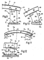
- Fig. 13, 14th illustrate a further conception of a bracket 80 for a sketchy only indicated bumper 10 a on a vehicle, not shown.
- This deformation member 80 approximately square cross-section, whose longitudinal axis is denoted by B, is connected with its bumper 10 a distal end edge 82 to a rear plate 84 of thickness i.
- Their length c and width q or q 1 are greater than the height h and the width b of the support cross-section.
- a lateral Plattenanformung 88 with part-circular, in particular semicircular edge 87 can be seen, which merges from the longitudinal edge 86 and in one of these adjacent transverse edge 89.
- the latter total length q is thus greater than the length q 1 of the other transverse edge 89 a .
- Plattenanformung 88 begins near the longitudinal edge 86 of this parallel adjacent, rising from the surface 85 lateral web 90 of the height h 1 and the axial length z, which corresponds to about twice the height of height h 1 .
- This flank web 90 terminates in each case at an axial distance z 1 to the transverse edges 88, 88 a of the rear plate 84.
- This distance z 1 moreover, also corresponds approximately to half the length z of the flank web 90.
- edge web 90 At the foot edge of the edge web 90 is in the region of the outer surface 92, an inclined, to the longitudinal edge 91 cross-sectional widening skirting 91 of the seat reinforcement formed.
- the distance t of its inner surface 92 from the adjacent longitudinal edge 86 of the rear plate 84 is indicated for the sake of clarity also on the other longitudinal edge 86 a ; its dimension corresponds approximately to half the distance t 1 of the slots 94 of that longitudinal edge 86 a .
- This rear plate 84 is, as I said, the stop member for a corresponding connection element of in Fig. 13, 14th Longitudinal member 30, not shown, and with its - - an outer side wall surface 81 of the bracket 80 adjacent - Flankensteg 90 a particularly favorable position security. Overall, the rear plate 84 forms a end noirrtiges reinforcing member for the connection of the bumper 12 a to the side member 30th
Description
Die Erfindung betrifft eine Stoßstange mit -- an dieser anzubringenden -- von ihr abragende Halterungen zum Befestigen an Längsträgern eines Fahrzeuges, wobei an der Stoßstange in Abstand zueinander als Druckgurt bzw. Zuggurt angeordnete Profilwände und ein Paar diese verbindender Flankenwände ein Hohlprofil bilden. Die Halterung kann als wenigstens eine Seitenwand und zwei an diese anschließende Querwände aufweisendes Hohlprofil mit einem dem Längsträger zugeordneten Hohlprofilträgerabschnitt gestaltet sowie das Hohlprofil der Stoßstange gegebenenfalls zumindest im Bereich der Halterungen gegenüber einer Querebene der Längsachse des Fahrzeugs gewölbt ausgeführt sein.The invention relates to a bumper with - on this to be mounted - projecting from her brackets for attachment to longitudinal members of a vehicle, wherein at the bumper at a distance from each other as a pressure belt or tension belt arranged profile walls and a pair of connecting flank walls form a hollow profile. The holder can be configured as at least one side wall and two adjacent thereto transverse walls exhibiting hollow profile with a longitudinal member associated hollow profile support section and the hollow profile of the bumper optionally be curved at least in the region of the brackets relative to a transverse plane of the longitudinal axis of the vehicle.
Eine Stoßstange mit die Längsachse ihres Längsträgers querenden plattenartigen Halterungen beschreibt die
Zum Befestigen der Stoßstange am Fahrzeug sind eine Vielzahl von Halterungen bekannt -- beispielsweise aus
Aus der
In der
In Kenntnis dieser Gegebenheiten hat sich der Erfinder das Ziel gesetzt, bei einer Stoßstange der eingangs erwähnten Art, die bei geringem Gewicht ein hohes Maß an Formhaltigkeit bei ausreichendem Kompensationsvermögen für die auftreffende Verformungsenergie aufweist, eine Möglichkeit zu schaffen, eine stabile Anbindung einer Stoßstange an das zugeordnete Fahrzeug zu ermöglichen sowie Verformungen bei Stoßbelastung erheblich zu mindern.In view of these circumstances, the inventor has set the goal, in a bumper of the type mentioned, which has a high degree of dimensional stability with sufficient compensation capacity for the incident deformation energy at low weight, a way to create a stable connection of a bumper to the To allow associated vehicle and to significantly reduce deformation under impact load.
Zur Lösung dieser Aufgabe führt die Lehre des unabhängigen Anspruches; die Unteransprüche geben günstige Weiterbildungen an. Zudem fallen in den Rahmen der Erfindung alle Kombinationen aus zumindest zwei der in der Beschreibung, der Zeichnung und/oder den Ansprüchen offenbarten Merkmale. Bei angegebenen Benennungsbereichen sollen auch innerhalb der genannten Grenzen liegende Werte als Grenzwerte offenbart und beliebig einsetzbar sein.To achieve this object, the teaching of the independent claim; the dependent claims indicate favorable developments. In addition, all combinations of at least two of the features disclosed in the description, the drawings and / or the claims fall within the scope of the invention. For given designation ranges, values lying within the specified limits should also be disclosed as limit values and used as desired.
Von besonderer Bedeutung ist es, dass dem der Stoßstange fernen Ende der -- aus einem Hohlprofil etwa rechteckigen Querschnitts bestehenden -- Halterung bzw. deren rahmenartiger Endkante als Anschlussorgan eine Heckplatte anliegt, die bevorzugt mit der Halterung verschweißt ist.Of particular importance is that the bumper's far end of - from a hollow section about rectangular Cross-section existing - holder or its frame-like end edge as a connecting member abut a rear plate, which is preferably welded to the bracket.
Von der Oberfläche der Heckplatte ragt erfindungsgemäß nahe einer Längskante sowie parallel dazu ein der Heckplatte ausgeformter Flankensteg auf, der in Einbaustellung einer Seitenwandaußenfläche der Haltung anliegt und so eine bessere Fixierung ermöglicht. Zur weitergehenden Verbesserung soll an die Außenfläche des Flankensteges ein -- seine der Heckplatte zugeordnete Längskante verstärkender -- Sockelstreifen angeformt sein, der unter Bildung einer zur benachbarten Längskante der Heckplatte geneigten Oberfläche einen sich zu seiner Längskante erweiternden Querschnitt aufweist. Nach einem anderen Merkmal der Erfindung entspricht zudem die axiale Länge des Flankensteges etwa der doppelten Länge seiner axialen Abstände von den Querkanten der Halteplatte. Im Übrigen entspricht die Höhe des Flankensteges etwa dessen halber Länge.From the surface of the rear plate protrudes according to the invention near a longitudinal edge and parallel to a rear plate formed flank web, which rests in the installed position of a side wall outer surface of the posture and thus allows better fixation. To further improve to the outer surface of the edge web a - the rear plate associated longitudinal edge reinforcing - base strip be formed, which has a to the adjacent longitudinal edge of the rear plate inclined surface has a widening to its longitudinal edge cross-section. According to another feature of the invention also corresponds to the axial length of the edge web about twice the length of its axial distances from the transverse edges of the support plate. Incidentally, the height of the edge bar corresponds to about half its length.
Erfindungsgemäß ist die Einheit aus Stoßstange und Halterung mit Kompensationselementen ausgestattet, welche Verformungen an der Halterung begrenzen, die durch die Stoßstange beeinflussende Druckkräfte ausgelöst werden, beispielsweise durch die Wucht eines Zusammenpralls.According to the invention, the bumper and support unit is provided with compensation elements which limit deformations on the support which are triggered by pressure forces influencing the bumper, for example by the force of a collision.
So liegt es im Rahmen der Erfindung, dass die Halterung zumindest einends angeschweißt sowie nahe der Schweißnaht mit wenigstens einem lochartigen Wanddurchbruch in ihrer Wandung ausgestattet ist. Bevorzugt wird dabei, den der Halterung benachbarten beiden Randbereichen der Stoßstange jeweils einen seitlichen Wanddurchbruch zuzuordnen; bevorzugt wird ein etwa kreisförmiger Rand dieses Wanddurchbruches. Letzterer nimmt jene Verformungskräfte auf, wenn er von einer kreisartigen Öffnung zu einem gestreckten Durchbruch wird.So it is within the scope of the invention that the holder is welded at least one end and is equipped near the weld with at least one hole-like wall opening in its wall. In this case, it is preferable to assign a lateral wall opening in each case to the two adjacent edge regions of the bumper adjacent to the holder; an approximately circular edge of this wall opening is preferred. The latter absorbs those deformation forces when it changes from a circular opening to a stretched breakthrough.
Die beschriebene Kompensation kann auch durch zumindest einen Sackschlitz erfolgen, der in den der Stoßstange fernen Randbereich der Halterung eingeschnitten wird und zu einer ihre Mittellinie kreuzenden Diametralebene geneigt ist. Am Sackschlitz bzw. an einem Paar von beidseits der Mittellinie und parallel zueinander verlaufenden Sackschlitzen endet die Verformungsbelastung.The described compensation can also be effected by at least one blind slot, which is cut into the edge region of the holder remote from the bumper and inclined to a diametral plane crossing its center line. At the blind slot or at a pair of both sides of the center line and mutually parallel blind slots ends the deformation load.
Ein weiteres Kompensationselement soll als Stab gestaltet sein. Dieser wird -- ähnlich dem vorstehend beschriebenen Sackschlitz -- dem der Stoßstange fernen Randbereich der Halterung zugeordnet als ein zu einer ihre Mittellinie kreuzenden Diametralebene geneigtes Profil, das aus einer unteren Schweißnaht ragt und der Oberfläche der Wandung anliegt. Bevorzugt werden zwei parallele Stäbe an der äußeren Oberfläche der Wandung. Im Falle einer Verformungsbelastung endet auch hier deren Gestaltungskraft an diesen Stäben.Another compensation element should be designed as a rod. This is - similar to the blind slot described above - assigned to the bumper remote edge portion of the holder as a inclined to its center line diametrical plane profile, which protrudes from a lower weld and rests against the surface of the wall. Preference is given to two parallel bars on the outer surface of the wall. In the case of a deformation load also ends their creative force on these rods.
Diese beiden Kompensationselemente können einzeln oder in Verbund mit dem anderen Element eingesetzt werden; dann enthält die Halterung die Wanddurchbrüche und ist an ihrer äußeren Oberfläche mit jenen Stäben ausgestattet.These two compensation elements can be used individually or in combination with the other element; then the holder contains the wall openings and is equipped on its outer surface with those rods.
Einer anderen erfindungsgemäßen Kompensationsart liegt ein von der Stirnkante der Stoßstange ausgehendes Paar von Längs- oder Stirnschlitzen zugrunde, deren jeder in einer der Flankenwände in deren an den Innen- oder Zuggurt der Stoßstange anschließenden Bereich angeordnet ist. Hier soll die Halterung mit dem Zuggurt durch eine Schweißnaht so verbunden werden, dass ein Teil der Wandung dieser Halterung unterhalb der Stirnschlitze an die Stoßstange angefügt ist. Der Stirnschlitz übergreift vorteilhafterweise die Mittellinie der Halterung, und der Endrand des Stirnschlitzes ist der Mittellinie der Halterung benachbart. Als günstig hat es sich dazu erwiesen, die Länge des Stirnschlitzes kürzer zu wählen als den Durchmesser der Halterung.Another type of compensation according to the invention is based on an emanating from the front edge of the bumper pair of longitudinal or end slots, each in one of the flank walls in the on the inner or Zuggurt the Bumper adjoining area is arranged. Here, the holder is to be connected to the tension belt by a weld so that a part of the wall of this bracket is added below the end slots to the bumper. The end slot advantageously overlaps the centerline of the holder, and the end edge of the end slot is adjacent the centerline of the holder. As low, it has been found to choose the length of the end slot shorter than the diameter of the holder.
Erfindungsgemäß können diesen Längs- oder Stirnschlitzen der Stoßstange die Wanddurchbrüche der Halterung und/oder die von deren Randkante ausgehenden Stirnschlitze zugeordnet sein. Statt der Stirnschlitze können auch die sich an die Außen- oder Oberfläche der Halterung anschmiegenden Stäbe zum Einsatz kommen.According to the invention, these longitudinal or end slots of the bumper may be associated with the wall openings of the holder and / or the end slots extending from the peripheral edge thereof. Instead of the end slots, the rods which conform to the outer or surface of the holder can also be used.
Als günstig hat es sich erwiesen, die Außenkontur derdie Längsachse der Halterung querenden -- Heckplatte rechteckig zu gestalten; dabei sollen die Längskanten der Heckplatte länger sein als ihre Querkanten, auch soll an einem der Übergänge zwischen einer Querkante sowie einer Längskante an letztere ein Plattenabschnitt angeformt sein mit einer teilkreisförmigen -- bevorzugt einer halbkreisartigen -- Außenkante. Deren Zentrum bestimmt die Lage eines Durchbruchs, dank dessen die Heckplatte an einem entsprechenden Gegenorgan des Längsträgers vorfixiert zu werden vermag. Zur endgültigen Festlegung sind nach einem weiteren Merkmal der Erfindung in den Bereichen der Übergänge der Querkanten zu den Längskanten -- also auch in den anderen Eckbereichen -- Durchbrüche für Verbindungsorgane vorgesehen.As low it has proven to make the outer contour of the longitudinal axis of the bracket trailing - rear plate rectangular; In this case, the longitudinal edges of the rear plate should be longer than their transverse edges, and should also be formed on one of the transitions between a transverse edge and a longitudinal edge of the latter a plate portion with a part-circular - preferably a semicircular - outer edge. Its center determines the position of a breakthrough, thanks to which the rear plate can be prefixed to a corresponding counter-member of the longitudinal member. For final determination, openings for connecting members are provided according to a further feature of the invention in the areas of the transitions of the transverse edges to the longitudinal edges - ie also in the other corner areas.
Der besseren Montage wegen erstrecken sich erfindungsgemäß zwischen dem Flankensteg sowie der ihm fern liegenden Längskante der Heckplatte zu deren Querkanten parallele Langlöcher, bevorzugt zwei Langlöcher, deren jeweiliger Abstand zur Innenfläche des Flankensteges etwa dem halben Abstand zur freien Längskante der Heckplatte entspricht.Because of the better installation, according to the invention extend parallel to the transverse edge parallel to the longitudinal edge of the rear plate to the transverse edges parallel slots, preferably two slots whose respective distance to the inner surface of the edge web corresponds approximately half the distance to the free longitudinal edge of the rear panel.
Es ergibt sich dank der Ausgestaltung der Heckplatte eine stabile Anbindung einer Stoßstange an einen der Längsträger des zugeordneten Fahrzeuges und damit eine günstige Lösung der vom Erfinder gesehenen Aufgabe.Thanks to the design of the rear plate, a stable connection of a bumper to one of the longitudinal members of the associated vehicle and thus a favorable solution of the task seen by the inventor results.
Weitere Vorteile, Merkmale und Einzelheiten der Erfindung ergeben sich aus der nachfolgenden Beschreibung bevorzugter Ausführungsbeispiele sowie anhand der Zeichnung; diese zeigt in
- Fig. 1:
- die Draufsicht auf eine Stoßstange in zwei unterschiedlichen Abschnitten mit an beiden Enden ebenfalls unterschiedlich ausgebildeten Halterungen zum jeweiligen Anschluss an einen Längsträger eines Fahrzeuges;
- Fig. 2:
- einen vergrößerten Ausschnitt aus dem rechten der Teil der
Fig. 1 nach dem Stande der Technik; - Fig. 3:
- eine Schrägsicht auf den in
Fig. 1 linken Teil der Stoßstange mit Halterung sowie einem teilweise geschnittenen Längsträger; - Fig. 4, 11:
- jeweils eine Schrägsicht auf eine Stoßstange mit zwei endwärtigen Halterungen;
- Fig. 5:
- die Schrägsicht auf den Gegenstand der
Fig. 4 nach einem Aufprall- oder Biegevorgang; - Fig. 6:
- eine vergrößerte Seitenansicht eines Endabschnittes der Stoßstange nach
Fig. 5 ; - Fig. 7, 9:
- jeweils eine Seitenansicht eines Abschnittes einer Stoßstange mit angefügter Halterung einer anderen Ausgestaltung;
- Fig. 8:
- die Stoßstange der
Fig. 7 nach einem Biegevorgang; - Fig. 10:
- die Stoßstange der
Fig. 9 nach einem Biegevorgang; - Fig. 12:
- die gegenüber
Fig. 11 vergrößerte Seitenansicht eines Abschnittes der Stoßstange nach einem Biegevorgang; - Fig. 13:
- eine Schrägsicht auf eine horizontal verlaufende Halterung einer weiteren Konzeption;
- Fig. 14:
- ein Element aus
Fig. 13 in vergrößerter Schrägsicht.
- Fig. 1:
- the top view of a bumper in two different sections with both ends also differently shaped brackets for connection to a side member of a vehicle;
- Fig. 2:
- an enlarged section of the right part of the
Fig. 1 in the state of the art; - 3:
- an oblique view of the in
Fig. 1 left part of the bumper with Holder and a partially cut longitudinal member; - 4, 11:
- in each case an oblique view of a bumper with two endwärtigen mounts;
- Fig. 5:
- the oblique view of the object of
Fig. 4 after an impact or bending process; - Fig. 6:
- an enlarged side view of an end portion of the bumper after
Fig. 5 ; - Fig. 7, 9:
- each a side view of a portion of a bumper with attached bracket of another embodiment;
- Fig. 8:
- the bumper of the
Fig. 7 after a bending process; - Fig. 10:
- the bumper of the
Fig. 9 after a bending process; - Fig. 12:
- the opposite
Fig. 11 enlarged side view of a portion of the bumper after a bending operation; - Fig. 13:
- an oblique view of a horizontally extending support another conception;
- Fig. 14:
- an element
Fig. 13 in enlarged oblique view.
Die Stoßstange 10 ist hier einem Paar von Fahrzeuglängsträgern 30 zugeordnet, die beidseits parallel zur Fahrzeuglängsachse A verlaufen. Sie sind ihrerseits aus zwei parallelen Seitenwänden 34 und diese verbindenden Querwänden 36 zusammengesetzt, die einen in
In dem den Stand der Technik wiedergebenden rechten Abschnitt der
Eine andere Ausgestaltung des Anschlusses des Hohlprofils 12 an den Fahrzeug-Längsträger 30 ist an dem in
Im Profilinnenraum 22 des Hohlprofils 12 ist einstückig mit den Profilwänden 14, 16 sowie den diese verbindenden Flankenwänden 18 eine -- parallel zu den Profilwänden 14, 16 gerichtete -- Querwand 24 mit jeweils einer zwischen dieser und den Profilwänden 14, 16 verlaufenden Mittelwand 26 vorgesehen. Diese Mittelwände 26 sind zueinander erkennbar höhen- bzw. seitenversetzt.In the
Der Anschluss des Hohlprofils 12 an den Fahrzeuglängsträger 30 wird hier durch ein aus einem -- seinerseits aus einer Aluminiumlegierung stranggepressten -- als Hohlprofil der Breite b von beispielsweise 55 mm sowie der Höhe h von 75 mm gestalteten Halteglied 46 hergestellt. An dessen dem Fahrzeuglängsträger 30 der Profilhöhe e zugeordneten und in diesem verschraubten Steckabschnitt 48 etwa rechteckigen Querschnitts -- aus zwei parallelen Seitenwänden 49 und diese verbindenden Querwänden 50 des Hohlprofils der Halterung 46 -- schließt ein Krümmungsabschnitt 52 an; die in
Die doppellagigen Schenkel 54 des so entstandenen rinnenartigen Krümmungsabschnitts 52 werden im Bereich von -- in der Zeichnung nicht erkennbaren -- Durchbrüchen von Schrauben 56 od.dgl. Verbindungsorganen durchsetzt, welche zudem in stoßstangenseitige Durchbrüche der Flankenwände 18 eingreifen. Entsprechende Durchbrüche für Verbindungsorgane 56a sind im Steckabschnitt 48 des Haltegliedes 46 vorgesehen. Diese Verbindungsorgane 56a lagern im Fahrzeuglängsträger 30 in Durchbrüchen 38.The double-layered legs 54 of the trough-
Die Flankenwände 18 sowie die diese verbindenden Profilwände 14, 16 der Stoßstange 11 in
Wird die Stoßstange 11 bei einem Aufprall -- vor allem bei einem Hochgeschwindigkeitsaufprall oder einem Prall gegen einen stehenden Pfosten -- durch eine beispielsweise in der Längsachse A angreifende äußere Kraft P gemäß
Auch an dem mit einer -- ein Einschubprofil 28 aufnehmenden -- Stoßstange 11 verbundenen rohrartigen Deformationselement 60 der
Statt der Sackschlitze 70 sind im Ausführungsbeispiel der
Die obere Schweißnaht 62 des rohrartigen Profilelements 61 der
In einem der
Die
An der in
An die Fußkante des Flankensteges 90 ist im Bereich von dessen Außenfläche 92 ein geneigter, sich zur Längskante 91 querschnittlich erweiternder Sockelstreifen 91 der Sitzverstärkung angeformt. Der Abstand t seiner Innenfläche 92 von der benachbarten Längskante 86 der Heckplatte 84 ist der besseren Übersicht halber auch an der anderen Längskante 86a angedeutet; sein Maß entspricht etwa dem halben Abstand t1 der Langlöcher 94 von jener Längskante 86a.At the foot edge of the
Nahe jenem Flankensteg 90 enden im Übrigen zwei zu dessen Innenfläche 92 rechtwinklig in der Heckplatte 84 verlaufende Langlöcher 96 der Breite g, die anderseits kurz vor der freien Längskante 86a enden. In den Bereichen der Plattenecken ist jeweils ein Durchbruch 98 zur Aufnahme eines nicht gezeigten Verbindungsorgans -- etwa einer Verbindungsschraube -- zu erkennen.Incidentally, two
Diese Heckplatte 84 ist, wie gesagt, das Anschlagorgan für ein entsprechendes Anschlusselement des in
Claims (19)
- A bumper (10, 10a, 11, 11a) with supports (60, 61, 80) protruding therefrom, for fastening to longitudinal members (30) of a vehicle, profile walls (14, 16) arranged spaced apart from one another as a compression chord and/or tension chord and a pair of flank walls (18) connecting said profile walls forming a hollow profile (12, 12a) on the bumper, the unit consisting of the bumper (10, 10a, 11, 11a) and the support (60, 61, 80) being provided with compensation elements (64, 70, 74, 76, 84) which limit deformations on the support which may be triggered by compressive forces (P) affecting the bumper, and a rear plate (84) bearing as a connecting member against the end of the support (80) remote from the bumper (10a) and/or the terminal edge (82) of said support, said rear plate being welded to the support, characterised in that a flank projection (90) is integrally formed in the vicinity of a longitudinal edge (86) of the rear plate (84) and parallel thereto, said flank projection bearing against a side wall outer surface (81) of the support (80) in the installed position.
- The bumper according to Claim 1, characterised in that the support (60) is welded onto at least one end and is provided in the vicinity of the welded seam (62) with at least one hole-type wall aperture (64) in the wall (58) thereof.
- The bumper according to Claim 2, characterised in that in each case a lateral wall aperture (64) is assigned to the two edge regions (17) of the bumper (11) adjacent to the support (60) (Fig. 4).
- The bumper according to Claim 2 or 3, characterised by an approximately circular edge (66) of the wall aperture (64).
- The bumper according to one of Claims 1 to 4, characterised in that at least one blind slot (70), which is inclined relative to a diametral plane intersecting the central line (M) thereof, is assigned to the edge region of the support (60) remote from the bumper (11), said blind slot running from the edge (57) of the support, preferably two blind slots being provided parallel to one another.
- The bumper according to one of Claims 1 to 4, characterised in that at least one rod (74), which is inclined relative to a diametral plane intersecting the central line (M) thereof, is assigned to the edge region of the support (60) remote from the bumper (11), said rod protruding from a welded seam (62t) and bearing against the surface (59) of the wall (58), in particular two parallel rods (70) being arranged on the outer surface (59) of the wall (58).
- The bumper according to Claim 1, characterised in that a pair of longitudinal slots or front slots (76) run from the front edge (20) of the bumper (11a), each of said slots being arranged in one of the flank walls (18) in the region thereof adjacent to the internal chord or tension chord (16) of the bumper (Fig. 12).
- The bumper according to Claim 7, characterised in that the support (61) is connected to the tension chord (16) by a welded seam (62) such that a part of the wall (58) of said support is joined-on below the front slots (76), the front slot overlapping the central line (M) of the support and the terminal edge (78) of the front slot being adjacent to the central line.
- The bumper according to Claim 7 or 8, characterised in that the length (nl) of the front slot (76) is shorter than the diameter (d) of the support (61).
- The bumper according to one of Claims 1 to 6, characterised in that the support (60) not only contains the wall aperture (64) but is also provided on its outer upper surface (59) with the blind slots (70) or the rods (74).
- The bumper according to one of claims 1 to 10, characterised in that the wall apertures (64) of the support (60) and/or the rods (74) on the outer surface or upper surface (59) thereof are assigned to the longitudinal slots or front slots (76) of the bumper (11a).
- The bumper according to one of Claims 1 to 11, characterised in that the wall apertures (64) of the support (60) and/or the blind slots (70) are assigned to the longitudinal slots or front slots (76) of the bumper (11a).
- The bumper according to one of Claims 1 to 12, characterised in that the rear plate (84) is welded to the terminal edge (82) of the support.
- The bumper according to Claim 13, characterised by a rectangular outer contour of the rear plate (84) traversing the longitudinal axis (B) of the support (80), the longitudinal edges (86, 86a) of said rear plate being longer than the transverse edges (89, 89a) thereof, a shaped plate portion (88) with an edge (87) in the shape of a pitch circle, in particular an approximately semi-circular edge, being integrally formed on one of the transitions between a transverse edge (89) and a longitudinal edge (86).
- The bumper according to Claim 14, characterised in that approximately in the centre of the surface of the shaped plate portion (88) defined by the edge (87), said surface corresponding in its thickness (i) to that of the remaining rear plate (84), an aperture (98) is provided and/or in each case at least one aperture for a connecting member is arranged in the regions of the transitions between the transverse edges (89, 89a) and the longitudinal edges (86, 86a).
- The bumper according to one of the preceding claims, characterised in that a base strip (93) reinforcing the longitudinal edge (91) of the flank projection, assigned to the rear plate (84), is integrally formed on the outer surface (92) of the flank projection, said base strip having a cross section which widens toward its longitudinal edge (91), in particular by forming a surface which is inclined relative to the adjacent longitudinal edge (86) of the rear plate (Fig. 13).
- The bumper according to one of the preceding claims, characterised in that the axial length (z) of the flank projection (90) corresponds to approximately double the length of its axial spacings (zl) from the transverse edges (89) of the rear plate (84) and/or the height (h1) of the flank projection (90) corresponds to approximately half the length (z) thereof.
- The bumper according to Claim 16 or 17, characterised in that slots (96) parallel to the transverse edges (89, 89a) thereof extend between the flank projection (90) and the longitudinal edge (86a) of the rear plate (84) located remotely therefrom, said slots preferably intersecting the longitudinal axis (Q) of the rear plate (84).
- The bumper according to Claim 18, characterised by two slots (96), the respective spacing thereof from the inner surface (94) of the flank projection (90) corresponding approximately to half the spacing (t1) relative to the longitudinal edge (86a).
Applications Claiming Priority (1)
| Application Number | Priority Date | Filing Date | Title |
|---|---|---|---|
| DE102006033822 | 2006-07-19 |
Publications (3)
| Publication Number | Publication Date |
|---|---|
| EP1880905A2 EP1880905A2 (en) | 2008-01-23 |
| EP1880905A3 EP1880905A3 (en) | 2009-08-05 |
| EP1880905B1 true EP1880905B1 (en) | 2014-03-12 |
Family
ID=38645903
Family Applications (1)
| Application Number | Title | Priority Date | Filing Date |
|---|---|---|---|
| EP20070014123 Not-in-force EP1880905B1 (en) | 2006-07-19 | 2007-07-19 | Bumper with supports |
Country Status (1)
| Country | Link |
|---|---|
| EP (1) | EP1880905B1 (en) |
Family Cites Families (9)
| Publication number | Priority date | Publication date | Assignee | Title |
|---|---|---|---|---|
| US4190276A (en) * | 1976-12-22 | 1980-02-26 | Mitsubishi Jidosha Kogyo Kabushiki Kaisha | Deformable impact absorbing device for vehicles |
| JPS594355U (en) | 1982-07-01 | 1984-01-12 | アイシン精機株式会社 | Bumper reinforcement material |
| US5080410A (en) | 1991-04-22 | 1992-01-14 | Chrysler Corporation | Vehicle bumper beam |
| US5875875A (en) * | 1996-11-05 | 1999-03-02 | Knotts; Stephen Eric | Shock isolator and absorber apparatus |
| FR2766437B1 (en) | 1997-07-28 | 1999-10-22 | Ecia Equip Composants Ind Auto | BUMPER FOR MOTOR VEHICLE AND METHODS OF MANUFACTURING THE SAME |
| US6485072B1 (en) * | 1999-12-15 | 2002-11-26 | Ford Global Technologies, Inc. | Bumper system for motor vehicles |
| CA2483845C (en) * | 2002-04-19 | 2012-09-04 | Magna International Inc. | Collision energy-absorbing device |
| DE10234253B3 (en) * | 2002-07-27 | 2004-04-08 | Hydro Aluminium Deutschland Gmbh | Crash box for motor vehicles |
| DE102004060088B3 (en) * | 2004-12-13 | 2006-02-16 | Benteler Automobiltechnik Gmbh | Bumper arrangement for vehicle, comprising crash box and hollow carrying element adjusted with tolerance between them |
-
2007
- 2007-07-19 EP EP20070014123 patent/EP1880905B1/en not_active Not-in-force
Also Published As
| Publication number | Publication date |
|---|---|
| EP1880905A2 (en) | 2008-01-23 |
| EP1880905A3 (en) | 2009-08-05 |
Similar Documents
| Publication | Publication Date | Title |
|---|---|---|
| DE602005004514T2 (en) | BUMPER ROD FOR ONE VEHICLE | |
| DE102005029738B4 (en) | Energy absorber element and this vehicle body using | |
| DE102011111644B4 (en) | Steering support member structure | |
| DE10305185B4 (en) | Bumper reinforcement | |
| EP3668758B1 (en) | Bumper cross-member | |
| DE102007042292B4 (en) | Plastic deformable double cell connection for the front of automobiles | |
| DE10040824B4 (en) | Steering column support beam structure | |
| EP2057041B1 (en) | Energy absorption device, especially for non-axial loads | |
| EP1132263B1 (en) | Wheel guard assembly for a vehicle | |
| EP1342625B1 (en) | Bumper with mounting means | |
| EP1717107A1 (en) | Bumper provided with supports | |
| DE102010006977A1 (en) | Motor vehicle front end | |
| DE112010006033T5 (en) | Vehicle bumper beam and method of making the same | |
| DE202007019296U1 (en) | Arrangement for attaching a bumper to side members of a vehicle | |
| WO2019072653A1 (en) | Bumper crossmember | |
| DE3003924A1 (en) | CAR BOX ASSEMBLY FOR ROAD AND RAIL VEHICLES | |
| DE102006041092A1 (en) | Crumple zone for passenger compartment of automobile body, has body component with extruded profile having hollow chambers that run transverse to extension direction of support profile and extend in high direction of automobile | |
| DE102014008712A1 (en) | Vehicle front structure | |
| DE102007033764B4 (en) | Bumper with brackets | |
| WO2006032439A1 (en) | Bumper device | |
| DE102006019653A1 (en) | Bumper system for vehicle has hollow profile structure with hollow profile insert supports into chassis frame | |
| EP1880905B1 (en) | Bumper with supports | |
| DE102021102365B4 (en) | Bumper assembly with additional support | |
| EP1277621B1 (en) | Bumper for a motor vehicle | |
| EP2090472B1 (en) | Bumper with supports for a vehicle |
Legal Events
| Date | Code | Title | Description |
|---|---|---|---|
| PUAI | Public reference made under article 153(3) epc to a published international application that has entered the european phase |
Free format text: ORIGINAL CODE: 0009012 |
|
| AK | Designated contracting states |
Kind code of ref document: A2 Designated state(s): AT BE BG CH CY CZ DE DK EE ES FI FR GB GR HU IE IS IT LI LT LU LV MC MT NL PL PT RO SE SI SK TR |
|
| AX | Request for extension of the european patent |
Extension state: AL BA HR MK YU |
|
| PUAL | Search report despatched |
Free format text: ORIGINAL CODE: 0009013 |
|
| AK | Designated contracting states |
Kind code of ref document: A3 Designated state(s): AT BE BG CH CY CZ DE DK EE ES FI FR GB GR HU IE IS IT LI LT LU LV MC MT NL PL PT RO SE SI SK TR |
|
| AX | Request for extension of the european patent |
Extension state: AL BA HR MK RS |
|
| 17P | Request for examination filed |
Effective date: 20091125 |
|
| 17Q | First examination report despatched |
Effective date: 20100108 |
|
| AKX | Designation fees paid |
Designated state(s): AT BE BG CH CY CZ DE DK EE ES FI FR GB GR HU IE IS IT LI LT LU LV MC MT NL PL PT RO SE SI SK TR |
|
| RAP1 | Party data changed (applicant data changed or rights of an application transferred) |
Owner name: 3A TECHNOLOGY & MANAGEMENT AG |
|
| RAP1 | Party data changed (applicant data changed or rights of an application transferred) |
Owner name: ENGINEERED PRODUCTS SWITZERLAND AG (LTD.) |
|
| RAP1 | Party data changed (applicant data changed or rights of an application transferred) |
Owner name: CONSTELLIUM SWITZERLAND AG |
|
| GRAP | Despatch of communication of intention to grant a patent |
Free format text: ORIGINAL CODE: EPIDOSNIGR1 |
|
| INTG | Intention to grant announced |
Effective date: 20131128 |
|
| GRAS | Grant fee paid |
Free format text: ORIGINAL CODE: EPIDOSNIGR3 |
|
| GRAA | (expected) grant |
Free format text: ORIGINAL CODE: 0009210 |
|
| AK | Designated contracting states |
Kind code of ref document: B1 Designated state(s): AT BE BG CH CY CZ DE DK EE ES FI FR GB GR HU IE IS IT LI LT LU LV MC MT NL PL PT RO SE SI SK TR |
|
| REG | Reference to a national code |
Ref country code: GB Ref legal event code: FG4D Free format text: NOT ENGLISH |
|
| REG | Reference to a national code |
Ref country code: CH Ref legal event code: EP |
|
| REG | Reference to a national code |
Ref country code: AT Ref legal event code: REF Ref document number: 656052 Country of ref document: AT Kind code of ref document: T Effective date: 20140315 |
|
| REG | Reference to a national code |
Ref country code: IE Ref legal event code: FG4D Free format text: LANGUAGE OF EP DOCUMENT: GERMAN |
|
| REG | Reference to a national code |
Ref country code: DE Ref legal event code: R096 Ref document number: 502007012842 Country of ref document: DE Effective date: 20140424 |
|
| REG | Reference to a national code |
Ref country code: NL Ref legal event code: VDEP Effective date: 20140312 |
|
| PG25 | Lapsed in a contracting state [announced via postgrant information from national office to epo] |
Ref country code: LT Free format text: LAPSE BECAUSE OF FAILURE TO SUBMIT A TRANSLATION OF THE DESCRIPTION OR TO PAY THE FEE WITHIN THE PRESCRIBED TIME-LIMIT Effective date: 20140312 |
|
| REG | Reference to a national code |
Ref country code: LT Ref legal event code: MG4D |
|
| PG25 | Lapsed in a contracting state [announced via postgrant information from national office to epo] |
Ref country code: SE Free format text: LAPSE BECAUSE OF FAILURE TO SUBMIT A TRANSLATION OF THE DESCRIPTION OR TO PAY THE FEE WITHIN THE PRESCRIBED TIME-LIMIT Effective date: 20140312 Ref country code: FI Free format text: LAPSE BECAUSE OF FAILURE TO SUBMIT A TRANSLATION OF THE DESCRIPTION OR TO PAY THE FEE WITHIN THE PRESCRIBED TIME-LIMIT Effective date: 20140312 Ref country code: CY Free format text: LAPSE BECAUSE OF FAILURE TO SUBMIT A TRANSLATION OF THE DESCRIPTION OR TO PAY THE FEE WITHIN THE PRESCRIBED TIME-LIMIT Effective date: 20140312 |
|
| PG25 | Lapsed in a contracting state [announced via postgrant information from national office to epo] |
Ref country code: LV Free format text: LAPSE BECAUSE OF FAILURE TO SUBMIT A TRANSLATION OF THE DESCRIPTION OR TO PAY THE FEE WITHIN THE PRESCRIBED TIME-LIMIT Effective date: 20140312 |
|
| PG25 | Lapsed in a contracting state [announced via postgrant information from national office to epo] |
Ref country code: EE Free format text: LAPSE BECAUSE OF FAILURE TO SUBMIT A TRANSLATION OF THE DESCRIPTION OR TO PAY THE FEE WITHIN THE PRESCRIBED TIME-LIMIT Effective date: 20140312 Ref country code: RO Free format text: LAPSE BECAUSE OF FAILURE TO SUBMIT A TRANSLATION OF THE DESCRIPTION OR TO PAY THE FEE WITHIN THE PRESCRIBED TIME-LIMIT Effective date: 20140312 Ref country code: BG Free format text: LAPSE BECAUSE OF FAILURE TO SUBMIT A TRANSLATION OF THE DESCRIPTION OR TO PAY THE FEE WITHIN THE PRESCRIBED TIME-LIMIT Effective date: 20140612 Ref country code: NL Free format text: LAPSE BECAUSE OF FAILURE TO SUBMIT A TRANSLATION OF THE DESCRIPTION OR TO PAY THE FEE WITHIN THE PRESCRIBED TIME-LIMIT Effective date: 20140312 Ref country code: IS Free format text: LAPSE BECAUSE OF FAILURE TO SUBMIT A TRANSLATION OF THE DESCRIPTION OR TO PAY THE FEE WITHIN THE PRESCRIBED TIME-LIMIT Effective date: 20140712 |
|
| PG25 | Lapsed in a contracting state [announced via postgrant information from national office to epo] |
Ref country code: SK Free format text: LAPSE BECAUSE OF FAILURE TO SUBMIT A TRANSLATION OF THE DESCRIPTION OR TO PAY THE FEE WITHIN THE PRESCRIBED TIME-LIMIT Effective date: 20140312 Ref country code: ES Free format text: LAPSE BECAUSE OF FAILURE TO SUBMIT A TRANSLATION OF THE DESCRIPTION OR TO PAY THE FEE WITHIN THE PRESCRIBED TIME-LIMIT Effective date: 20140312 Ref country code: PL Free format text: LAPSE BECAUSE OF FAILURE TO SUBMIT A TRANSLATION OF THE DESCRIPTION OR TO PAY THE FEE WITHIN THE PRESCRIBED TIME-LIMIT Effective date: 20140312 |
|
| REG | Reference to a national code |
Ref country code: DE Ref legal event code: R097 Ref document number: 502007012842 Country of ref document: DE |
|
| PG25 | Lapsed in a contracting state [announced via postgrant information from national office to epo] |
Ref country code: PT Free format text: LAPSE BECAUSE OF FAILURE TO SUBMIT A TRANSLATION OF THE DESCRIPTION OR TO PAY THE FEE WITHIN THE PRESCRIBED TIME-LIMIT Effective date: 20140714 |
|
| PLBE | No opposition filed within time limit |
Free format text: ORIGINAL CODE: 0009261 |
|
| STAA | Information on the status of an ep patent application or granted ep patent |
Free format text: STATUS: NO OPPOSITION FILED WITHIN TIME LIMIT |
|
| PG25 | Lapsed in a contracting state [announced via postgrant information from national office to epo] |
Ref country code: DK Free format text: LAPSE BECAUSE OF FAILURE TO SUBMIT A TRANSLATION OF THE DESCRIPTION OR TO PAY THE FEE WITHIN THE PRESCRIBED TIME-LIMIT Effective date: 20140312 |
|
| 26N | No opposition filed |
Effective date: 20141215 |
|
| PG25 | Lapsed in a contracting state [announced via postgrant information from national office to epo] |
Ref country code: LU Free format text: LAPSE BECAUSE OF FAILURE TO SUBMIT A TRANSLATION OF THE DESCRIPTION OR TO PAY THE FEE WITHIN THE PRESCRIBED TIME-LIMIT Effective date: 20140719 |
|
| REG | Reference to a national code |
Ref country code: CH Ref legal event code: PL |
|
| REG | Reference to a national code |
Ref country code: DE Ref legal event code: R097 Ref document number: 502007012842 Country of ref document: DE Effective date: 20141215 |
|
| PG25 | Lapsed in a contracting state [announced via postgrant information from national office to epo] |
Ref country code: IT Free format text: LAPSE BECAUSE OF FAILURE TO SUBMIT A TRANSLATION OF THE DESCRIPTION OR TO PAY THE FEE WITHIN THE PRESCRIBED TIME-LIMIT Effective date: 20140312 |
|
| REG | Reference to a national code |
Ref country code: IE Ref legal event code: MM4A |
|
| PG25 | Lapsed in a contracting state [announced via postgrant information from national office to epo] |
Ref country code: CH Free format text: LAPSE BECAUSE OF NON-PAYMENT OF DUE FEES Effective date: 20140731 Ref country code: LI Free format text: LAPSE BECAUSE OF NON-PAYMENT OF DUE FEES Effective date: 20140731 |
|
| REG | Reference to a national code |
Ref country code: FR Ref legal event code: PLFP Year of fee payment: 9 |
|
| PG25 | Lapsed in a contracting state [announced via postgrant information from national office to epo] |
Ref country code: SI Free format text: LAPSE BECAUSE OF FAILURE TO SUBMIT A TRANSLATION OF THE DESCRIPTION OR TO PAY THE FEE WITHIN THE PRESCRIBED TIME-LIMIT Effective date: 20140312 |
|
| PG25 | Lapsed in a contracting state [announced via postgrant information from national office to epo] |
Ref country code: IE Free format text: LAPSE BECAUSE OF NON-PAYMENT OF DUE FEES Effective date: 20140719 |
|
| REG | Reference to a national code |
Ref country code: AT Ref legal event code: MM01 Ref document number: 656052 Country of ref document: AT Kind code of ref document: T Effective date: 20140719 |
|
| PG25 | Lapsed in a contracting state [announced via postgrant information from national office to epo] |
Ref country code: AT Free format text: LAPSE BECAUSE OF NON-PAYMENT OF DUE FEES Effective date: 20140719 |
|
| PG25 | Lapsed in a contracting state [announced via postgrant information from national office to epo] |
Ref country code: MC Free format text: LAPSE BECAUSE OF FAILURE TO SUBMIT A TRANSLATION OF THE DESCRIPTION OR TO PAY THE FEE WITHIN THE PRESCRIBED TIME-LIMIT Effective date: 20140312 |
|
| PG25 | Lapsed in a contracting state [announced via postgrant information from national office to epo] |
Ref country code: GR Free format text: LAPSE BECAUSE OF FAILURE TO SUBMIT A TRANSLATION OF THE DESCRIPTION OR TO PAY THE FEE WITHIN THE PRESCRIBED TIME-LIMIT Effective date: 20140613 Ref country code: MT Free format text: LAPSE BECAUSE OF FAILURE TO SUBMIT A TRANSLATION OF THE DESCRIPTION OR TO PAY THE FEE WITHIN THE PRESCRIBED TIME-LIMIT Effective date: 20140312 |
|
| REG | Reference to a national code |
Ref country code: FR Ref legal event code: PLFP Year of fee payment: 10 |
|
| PG25 | Lapsed in a contracting state [announced via postgrant information from national office to epo] |
Ref country code: TR Free format text: LAPSE BECAUSE OF FAILURE TO SUBMIT A TRANSLATION OF THE DESCRIPTION OR TO PAY THE FEE WITHIN THE PRESCRIBED TIME-LIMIT Effective date: 20140312 Ref country code: HU Free format text: LAPSE BECAUSE OF FAILURE TO SUBMIT A TRANSLATION OF THE DESCRIPTION OR TO PAY THE FEE WITHIN THE PRESCRIBED TIME-LIMIT; INVALID AB INITIO Effective date: 20070719 Ref country code: BE Free format text: LAPSE BECAUSE OF FAILURE TO SUBMIT A TRANSLATION OF THE DESCRIPTION OR TO PAY THE FEE WITHIN THE PRESCRIBED TIME-LIMIT Effective date: 20140731 |
|
| REG | Reference to a national code |
Ref country code: FR Ref legal event code: PLFP Year of fee payment: 11 |
|
| REG | Reference to a national code |
Ref country code: FR Ref legal event code: PLFP Year of fee payment: 12 |
|
| PGFP | Annual fee paid to national office [announced via postgrant information from national office to epo] |
Ref country code: CZ Payment date: 20210712 Year of fee payment: 15 Ref country code: FR Payment date: 20210726 Year of fee payment: 15 |
|
| PGFP | Annual fee paid to national office [announced via postgrant information from national office to epo] |
Ref country code: DE Payment date: 20210728 Year of fee payment: 15 Ref country code: GB Payment date: 20210727 Year of fee payment: 15 |
|
| REG | Reference to a national code |
Ref country code: DE Ref legal event code: R119 Ref document number: 502007012842 Country of ref document: DE |
|
| GBPC | Gb: european patent ceased through non-payment of renewal fee |
Effective date: 20220719 |
|
| PG25 | Lapsed in a contracting state [announced via postgrant information from national office to epo] |
Ref country code: FR Free format text: LAPSE BECAUSE OF NON-PAYMENT OF DUE FEES Effective date: 20220731 Ref country code: CZ Free format text: LAPSE BECAUSE OF NON-PAYMENT OF DUE FEES Effective date: 20220719 |
|
| PG25 | Lapsed in a contracting state [announced via postgrant information from national office to epo] |
Ref country code: GB Free format text: LAPSE BECAUSE OF NON-PAYMENT OF DUE FEES Effective date: 20220719 Ref country code: DE Free format text: LAPSE BECAUSE OF NON-PAYMENT OF DUE FEES Effective date: 20230201 |
|
| P01 | Opt-out of the competence of the unified patent court (upc) registered |
Effective date: 20230411 |