EP1880781A1 - Flaskless molding method - Google Patents
Flaskless molding method Download PDFInfo
- Publication number
- EP1880781A1 EP1880781A1 EP06746214A EP06746214A EP1880781A1 EP 1880781 A1 EP1880781 A1 EP 1880781A1 EP 06746214 A EP06746214 A EP 06746214A EP 06746214 A EP06746214 A EP 06746214A EP 1880781 A1 EP1880781 A1 EP 1880781A1
- Authority
- EP
- European Patent Office
- Prior art keywords
- molding
- flask
- cope
- sand
- drag
- Prior art date
- Legal status (The legal status is an assumption and is not a legal conclusion. Google has not performed a legal analysis and makes no representation as to the accuracy of the status listed.)
- Granted
Links
- 238000000465 moulding Methods 0.000 title claims abstract description 89
- 238000000034 method Methods 0.000 title claims abstract description 36
- 239000003110 molding sand Substances 0.000 claims description 46
- 238000002347 injection Methods 0.000 claims description 24
- 239000007924 injection Substances 0.000 claims description 24
- 239000004576 sand Substances 0.000 abstract description 4
- 238000004519 manufacturing process Methods 0.000 abstract 7
- 230000033001 locomotion Effects 0.000 description 9
- 238000005273 aeration Methods 0.000 description 4
- 230000013011 mating Effects 0.000 description 3
- 238000007664 blowing Methods 0.000 description 2
- 230000000694 effects Effects 0.000 description 1
- 238000003780 insertion Methods 0.000 description 1
- 230000037431 insertion Effects 0.000 description 1
- 238000012986 modification Methods 0.000 description 1
- 230000004048 modification Effects 0.000 description 1
Images


Classifications
-
- B—PERFORMING OPERATIONS; TRANSPORTING
- B22—CASTING; POWDER METALLURGY
- B22C—FOUNDRY MOULDING
- B22C11/00—Moulding machines characterised by the relative arrangement of the parts of same
- B22C11/10—Moulding machines characterised by the relative arrangement of the parts of same with one or more flasks forming part of the machine, from which only the sand moulds made by compacting are removed
-
- B—PERFORMING OPERATIONS; TRANSPORTING
- B22—CASTING; POWDER METALLURGY
- B22C—FOUNDRY MOULDING
- B22C15/00—Moulding machines characterised by the compacting mechanism; Accessories therefor
- B22C15/28—Compacting by different means acting simultaneously or successively, e.g. preliminary blowing and finally pressing
Definitions
- This invention relates to a molding method, and, more particularly, to a flaskless molding method in which formed molds are removed from flasks after the molds are formed.
- Japanese Early-Patent Publication No. 62 [this coresponds to the year1987]-16736 discloses a flaskless molding machine for molding stacked flaskless molds by using two pairs of a cope flask and a drag flask in which one cope flask and one drag flask form one pair.
- a squeeze station mounted on the upper side of a machinery mount is a squeeze station that horizontally squeezes molding sand horizontally as viewed from the floor level.
- a stripping station mounted on the lower side or near the floor level.
- the present invention provides methods for molding stacked upper and lower molds with a flaskless molding machine that includes a cope flask and a drag flask.
- Each flask defines an opening and has at least one sand-filling port for injecting molding sand into the opening, a match plate having upper and lower patterns on top and bottom faces corresponding to the cope and drag flasks, and upper and lower squeezing members, each squeezing member being insertable in and retractable from the corresponding opening of the corresponding flask for squeezing the molding sand to be molded.
- One of the methods comprises the steps of defining upper and lower molding spaces by inserting the upper and lower squeezing members into the respective openings of the respective flasks opposed to the respective patterns of the match plate such that the upper molding space is defined by the cope flask, the top face of the match plate, and the upper squeezing member, and the lower molding space is defined by the drag flask, the bottom face of the match plate, and the lower squeezing member, wherein each molding space has an initial volume; a first injection of the molding sand into each molding space that has the initial volume, from the sand-filling ports; increasing the volume in each molding space above the initial volume by retracting the upper and lower squeezing members by a predetermined length; a second injection of the molding sand into each molding space that has the increased volume, from the sand-filling ports; advancing the upper and lower squeezing members, followed by the second injecting step, to squeeze the molding sand within the upper and lower molding spaces to mold stacked
- the cope and drag flasks are in their vertical positions during the steps of the first and second injections of the molding sand, whereas they are in their horizontal positions during the step of removing the resulting molds.
- the step of defining the molding spaces is carried out while the cope and drag flasks are returning from their horizontal positions, during which the stripping of the molds has been completed, to their vertical positions.
- Another method of the present invention comprises clamping and holding the match plate between the cope flask and the drag flask, wherein the cope and drag flasks are in their horizontal positions; defining upper and lower molding spaces by inserting the upper and lower squeezing members into the respective openings of the respective flasks opposed to the respective patterns of the match plate such that the upper molding space is defined by the cope flask, the top face of the match plate, and the upper squeezing member, and the lower molding space is defined by the drag flask, the bottom face of the match plate, and the lower squeezing member, wherein each molding space has an initial volume; turning the cope and drag flasks and the match plate to their vertical positions in unison; a first injection of the molding sand into each molding space that has the initial volume, from the sand-filling ports; increasing the volume in each molding space above the initial volume by retracting the upper and lower squeezing members by a predetermined length; a second injection of the molding sand into each
- the method may, if necessary, further comprise the step of setting a core in each mold before the step of stacking the cope flask and the drag flask is carried out.
- the step of defining the molding spaces is carried out while the cope and drag flasks, and the match plate, are in their horizontal positions.
- the sand-filling ports for injecting the molding move upward.
- the step of the second injection may begin after each molding space has reached the desired volume and thus the step of increasing the volume in each molding space is completed.
- the step of the second injection may be applied while the upper and lower squeezing members are still retracted during the step of increasing the volume in each molding space such that the step of the second injection can begin before the step of increasing the volume in each molding space has been completed by reaching the desired volume.
- each of the upper and lower squeeze members may be a squeezing plate or a squeezing foot.
- Figs. 1 to 4 show the flaskless molding machine to implement the molding method of the present invention.
- the molding machine includes a rectangular machinery mount whose inner chamber includes a station P for defining molding spaces, a sand-supplying station S, and a core setting/mold stripping station W
- the station P which defines the molding spaces, has two pairs of a cope flask 2 and a drag flask 3. Each flask defines an opening and has a sand-filling port on its sidewall for supplying molding sand. Although in this embodiment one flask has just one sand-filling port, one or more sand-filling ports may be provided with the one flask.
- the station P includes a shuttle 4 for carrying in and carrying out a match plate 5. Both faces of it are formed with patterns, between one of the two pairs of the cope flask 2 and the drag flask 3, and a squeezing mechanism 9.
- the squeezing mechanism 9 includes an upper squeeze plate 6 and a lower squeeze plate 7.
- the squeeze mechanism 9 is pivotally supported on a supporting shaft 8 that is mounted on the machinery mount such that the squeeze mechanism 9 can be reversiblely rotated about the supporting shaft 8 in the vertical plane.
- the range of the rotating or pivoting motion of the squeezing mechanism 9 is between the vertical position and horizontal position. In the vertical position, a pair of the cope flask 2 and the drag flask 3 that are clamped and that hold the match plate 5 therebetween are in their vertical positions. Meanwhile, they are in their horizontal positions at the horizontal position of the rotating motion of the squeezing mechanism 9.
- the station P which defines the molding spaces, also has a transverse cylinder 10 for reversiblely rotating the squeeze mechanism 9.
- the sand-supplying station S includes a sand-supplying device 11 for filling molding sand into a pair of the cope flask 2 and the drag flask 3 that have been in the vertical position, by extending the cylinder 10 through the sand-filling ports.
- the core setting/mold stripping station W includes mold-stripping equipment 12 for stripping the resulting upper half-mold and the lower half-mold from the paired cope and flask 2 and drag flask 3, which are positioned in their horizontal positions and which are stacked such that they contain the upper half-mold and the lower half-mold.
- the core setting/mold stripping station W also includes a rotating mechanism 13 for alternatively and intermittently rotating two pairs of the stacked cope flasks 2 and drag flasks 3 in the horizontal state, in which one pair of the flasks and another pair of flasks are deposed in a parallel relation on a horizontal level, one at a time, between the squeezing mechanism 9 and the mold-stripping device 12.
- the rotating mechanism 13 also can be engaged with each cope flask 2 to move it up and down.
- a pair of connecting rods 14 is vertically and slidably suspended from the front and rear sides of the cope flask 2. The lower ends of the connecting rods 14 can be engaged with the drag flask 3.
- Engaging members 2a are attached to the center positions of the opposed sides of the cope flask 2, while engaging members 3a are attached to the ends of the opposed sides of the drag flask 3 when it is in the squeezing mechanism 9 such that the one pair of the cope flask 2 and the drag flask 3 can be supported by the rotating mechanism 13.
- each engaging member 2a or 3a may have a convex shape with a bore for receiving a pin (not shown) so as to be connected to a mating upper engaging member 37 or the mating lower engaging member 39 (discussed below) of the rotating mechanism 13. Because the profile of each engaging member 2a or 3a may take any form that is suitable for being connected or detachably attached to the mating engaging member 37 or 39, it may take, e.g., a concave profile.
- the shuttle 4 for carrying the match plate includes a ring member 15 that is fitted on the supporting shaft 8 of the squeezing mechanism 9, and a cylinder 16, which is pivotally attached to the sand-supplying device 11.
- the end of a piston rod of the cylinder 16 is pivotally connected to a portion of the ring member 15.
- the shuttle 4 also includes a pair of cantilevered arms 17, the bases of the ends are attached to the ring member 15.
- the shuttle 4 also includes a suspended truck 45 that is laterally movable when the match plate 5 is placed on it.
- the truck 45 is lowered by a predetermined, relatively short, distance by means of the cope flask 2, while the paired and cantilevered arms 17 are pivoted up and down by a telescopic motion of the cylinder 16 such that the arms 17 are engaged with and disengaged from the truck 45.
- the truck 45 runs on rails (not shown) that are provided on the cope flask 2 and the drag flask 3, to carry in and carry out the match plate 5 between the horizontal cope flask 2 and drag flask 3 in the squeezing mechanism 9.
- the cylinder 16 may be replaced with, e.g., a motor, etc.
- a rotating frame 18 is rotatably fitted to the approximate center portion of the supporting shaft 8, which is mounted on the center of the upper surface of the machinery mount 1.
- the rotating frame 18 can thus be reversibly rotated in the vertical plane.
- the right side of the rotating frame 18 is provided with a pair of vertical, elongated guiding arms 19.
- the guiding arms 19 are positioned in the rear and front in relation to each other, to form a predetermined distance therebetween.
- a reverse-L-shaped upper vertically-moving frame 20 and an L-shaped lower vertically-moving frame 21 are vertically and slidably mounted on and across the upper portions and the lower portions, respectively, of two guiding rods 19, by means of holders, each of which is integrally provided with a corresponding frame 20 or 21.
- the upper vertically-moving frame 20 and the lower vertically-moving frame 21 can be moved close to and away from each other by a telescopic motion of an upwardly-facing cylinder 22 and a downwardly-facing cylinder 23, respectively.
- These cylinders 22, 23 are mounted on the rotating frame 18.
- the upper vertically-moving frame 20 has a plurality of cylinders 24 for advancing and retracting the upper squeezing plate 6, while the lower vertically-moving frame 21 has a plurality of cylinders 25 for advancing and retracting the lower squeezing plate 7.
- the horizontal surface of each squeezing plate 6 or 7 has a cross section that suffices to press the corresponding cope or drag flask 2 or 3.
- the cylinders for driving the squeezing plates 6 and 7 cooperate to move in unison with the rotating frame 18.
- the cylinders may be fixed on the fixed portions.
- one group of the cylinders of the squeezing plate 6 or 7 may cooperatively move in unison with the rotating frame, and the other group of cylinders, of the corresponding squeezing plate, may be fixed on the fixed portion.
- the sand-supplying device 11 which is mounted on the top of the machinery mount 1 (near the left side in the figure), includes two aeration tanks 27 so as to separately introduce the molding sand into the cope flask 2 and the drag flask 3, while the injected molding sand is floated or fluidized ("aeration- injecting process ") by compressed air with a low pressure.
- just one aeration tank may be used to fill the molding sand into both the cope flask 2 and the drag flask 3.
- the aeration-injecting sand for floating or fluidizing the molding sand using the compressed air with the low pressure is disclosed, in, e.g., U.S. Patent No. 6,749,003 B2 , assigned to the applicant of the present application. It was found that the desirable pressures of the low-pressure air are from 0.05 Mpa to 0.18 Mpa.
- a suitable injecting process that can be used for the present invention is not limited to the fluidizing and injecting process. For example, a blowing injecting process using compressed air with a higher pressure may be used in the present invention.
- the sand-supplying device 11 may be connected to a decompressor (not shown) to be used together with air at a low pressure, i.e., below atmospheric pressure, in either the aeration-injecting process or the blowing-injecting process.
- a decompressor not shown
- the mold-stripping device 12 includes a stripping plate 28, which is insertable in and retractable from the overlapped horizontal cope flask 2 and drag flask 3. That stripping plate 28 is attached to the lower end of the piston rod of a downwardly-facing cylinder 29 that is mounted on the roof of the machinery mount 1.
- the stripping plate 28 can be moved vertically by a telescopic motion of the cylinder 29.
- a receiving table 30 Placed intermediately below the stripping plate 28 is a receiving table 30 for receiving an upper half-mold and a lower half-mold to be withdrawn from the cope flask 2 and the drag flask 3, respectively.
- the receiving table 30 is moved vertically by a pantograph 32 that can be extended and retracted by telescopic motions of a cylinder 31.
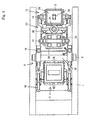
- the pantograph 32 may be replaced with a common lift table that is moved by a suitable cylinder. However, using the pantograph 32 as a driver for elevationally moving the receiving device 30, as in this embodiment, requires no pit for receiving the driver on the floor level on which the molding machine is installed (see Fig. 2).
- a vertically elongated, rotary shaft 33 is horizontally and rotatably mounted on the machinery mount 1.
- the upper end of the rotary shaft 33 is connected to the output of a motor 34, which is mounted on the top of the machinery mount 1.
- the rotary shaft 33 can be reversibly turned within a turning range of 180° by driving the motor 34.
- the motor 34 may be replaced with a suitable cylinder.
- the turning range of 180° of the rotary shaft 33 is just an example of its possible turning ranges for transferring the resulting mold from the on-site position where the mold is formed to the mold-stripping equipment 12 by the rotating mechanism 13. Because this turning range is defined and based on the site where the mold-stripping equipment 12 is installed, it is not limited to the 180°.
- the equipment 12 may be installed in any site, based on the desirable turning range of the shaft.
- the upper portion of the rotary shaft 33 has a supporting member 35 from which two pairs of guiding rods 36 are suspended. They are arranged in a back and front relationship to form a predetermined distance therebetween such that they are opposed to each other across the rotary shaft 33 that is centered therebetween.
- the upper engaging member 37 is vertically and slidably fitted on each pair of the guiding rods 36 to engage the engaging members 2a.
- the upper engaging member 37 is attached to the distal end of the piston rod of the cylinder 38 that is mounted on the rotary shaft 33.
- the upper engaging member 37 can thus be vertically moved by a telescopic motion of the cylinder 38.
- the lower ends of the two pairs of the guiding rods 36 are attached to a lower engaging member 39, which that can be engaged to the engaging members 3a of the two drag flasks 3.
- One of the functions of a mold ejector 40 is to push out the upper and lower half-molds, which are drawn from the cope flask 2 and the drag flask 3, from the receiving table 30.
- the match plate 5 is carried in between the horizontal cope and drag flasks 2 and 3 by extending the cylinder 16 of the shuttle 4.
- the cope flask 2 and the drag flask 3 are then moved closer to each other by means of the upper and lower vertically-moving frames 20 and 21 by retracting both the upwardly-facing cylinder 22 and the downwardly-facing cylinder 23 of the squeezing mechanism 9.
- the cope flask 2 and the drag flask 3 are then clamped, and hold the match plate 5 therebetween, while the clustered cylinders 24 and 25 are extended by a predetermined stroke length.
- the volume of each molding space in this state refers to the initial volume.
- the predetermined stroke length of the extending motion of the clustered cylinder 24 or 25 and thus the predetermined length of the insertion of the upper squeeze plate 6 or the lower squeeze plate 7 corresponds to the initial volume of the molding space to be defined.
- the clustered cylinders 24, 25 may be replaced with a combination of just one large-diameter cylinder and a guide pin.
- the cylinder 10 is extended to rotate the squeeze mechanism 9 clockwise about the supporting shaft 8 such that the paired cope and drag flasks 2 and 3, and the match plate 5, are positioned at their vertical positions while the sand-filling ports are raised.
- the raised sand-filling ports abut the lower ends of the two aeration tanks 27 of the sand-supplying device 11 (see Fig. 4).
- the paired molding spaces may be simultaneously defined.
- two molding spaces may be separately defined at different times.
- the sand-supplying device 11 then injects the molding sand into the paired upper and lower molding spaces through the sand-filling ports (a first injection step), using any suitable injecting method, such as aeration injecting with compressed air that has a low pressure, namely, below atmospheric pressure.
- the clustered cylinders 24 and 25 are retracted by the predetermined stroke length to retract the upper and lower squeeze plates 6 and 7 in immediate proximity to the corresponding openings of the paired cope flask 6 and drag flask 7. Therefore, the volume of each molding space is increased from its initial volume.
- the sand-supplying device 11 then re-injects the molding sand into the increased upper and lower molding spaces through the sand-filling ports (a second injection step).
- the paired cope flask 2 and drag flask 3, and the match plate 5, are returned to their horizontal positions.
- the clustered cylinders 24, 25 are extended such that the upper squeezing plate 6 and lower squeezing plate 7 move into the corresponding flasks to squeeze the molding sand within the two molding spaces.
- the molding sand is squeezed, followed by the two steps of injecting the molding sand.
- the first injecting step is carried out when each molding space has the initial volume.
- the second injecting step is applied to the increased molding spaces.
- the two steps of injecting the molding sand result in the increased hardness of the mold. This remarkable effect may be seen at the portions of the molds near the openings of the paired cope flask 2 and drag flask 3 that contain the molds.
- the first injecting step is applied to the molding spaces, each of which has the initial volume.
- the second injecting step is applied after the increased volumes of the molding spaces, caused by retracting the upper and lower squeeze plates 6 and 7, have been completed.
- the second injecting step may be begun. Accordingly, the blowing of the molding sand into the molding spaces may be continued without any interruption between the first injection step and the second injection step.
- the upwardly-facing cylinder 22 and the downwardly-facing cylinder 23 are extended such that the upper vertically-moving frame 20 and the lower vertically-moving frame 21 are spaced apart from each other.
- the cope flask 2 which contains the half-mold, which is produced by squeezing the molding sand, is lifted by means of the upper engaging member 37 to separate it from the match plate 5 by extending the cylinder 38 of the rotating mechanism 13. Meanwhile, the drag flask 3 is disposed on the lower engaging member 39 of the rotating member 13. The match plate 5 is then carried out from between the cope flask 2 and the drag flask 3 by means of the paired arms 17, by retracting the cylinder 16.
- the motor 34 of the rotating mechanism 13 is driven to turn the rotary shaft 33 in a predetermined range such that the paired upper flask 2 and drag flask 3, each of which contains a mold, are transferred to the mold-stripping equipment 12. A core may then be disposed in each mold, if necessary.
- the cylinder 38 is then retracted to lower the cope flask 2 that contains the mold by means of the engaging member 37 such that the cope flask 2 and the drag flask 3 are stacked.
- the cylinder 31 of the mold-stripping equipment 12 is then extended to rise on the receiving table 30 such that the cope flask 2 and drag flask 3 that contain the molds are disposed on the receiving table 30.
- the cylinder 29 of the mold-stripping equipment 12 is extended such that the stripping plate 28 contacts the half-mold within the cope flask 2.
- the cylinder 31 is then retracted to lower the stripping plate 28 and the receiving table 30 in a cooperative relationship to strip the half-molds from the paired cope flask 2 and drag flasks 3.
- the cylinder 31 is then retracted at the level at which the half-molds are to be ejected such that the ejector 40 is pushed off the paired upper and lower half-molds from the receiving table 40.
- a core be put in each formed half-mold, if so needed. If so, a core is put in each preceding formed half-mold before the cope flask 2 and the drag flask 3, each containing a new formed half-mold, are rotated and thus transferred to the mold-stripping equipment 12. The paired cope flask 2 and drag flask 3 are then stacked on each other to push out the half-molds in them, as discussed above.
- squeezing means are shown as the upper and lower squeezing plates 6 and 7, they may be replaced with squeeze feet that are separately controllable by means of restrictive hydraulic cylinders, and are arranged in respective segments.
Abstract
Description
- This invention relates to a molding method, and, more particularly, to a flaskless molding method in which formed molds are removed from flasks after the molds are formed.
- Japanese Early-Patent Publication No. 62 [this coresponds to the year1987]-16736 discloses a flaskless molding machine for molding stacked flaskless molds by using two pairs of a cope flask and a drag flask in which one cope flask and one drag flask form one pair. In this machine, mounted on the upper side of a machinery mount is a squeeze station that horizontally squeezes molding sand horizontally as viewed from the floor level. Further, mounted on the lower side or near the floor level is a stripping station for matching the molds and removing them vertically from the flasks as viewed from the floor level. Two pairs of the cope flask and the drag flask are alternately and intermittently and reciprocatingly moved between the squeeze station and the stripping station. With this arrangement, because an interchangeable match plate to be sandwiched between the cope and drag flasks can be exchanged near the floor level, the necessary labor is reduced.
- The foregoing conventional machine, however, may encounter a problem. It is that insufficient molding sand might be charged into the flasks, and thus the resulting molds might lack the desired hardness. Accordingly, there is a need for a flaskless molding method that can steadily and readily produce molds having the desired hardness.
- The present invention provides methods for molding stacked upper and lower molds with a flaskless molding machine that includes a cope flask and a drag flask. Each flask defines an opening and has at least one sand-filling port for injecting molding sand into the opening, a match plate having upper and lower patterns on top and bottom faces corresponding to the cope and drag flasks, and upper and lower squeezing members, each squeezing member being insertable in and retractable from the corresponding opening of the corresponding flask for squeezing the molding sand to be molded. One of the methods comprises the steps of defining upper and lower molding spaces by inserting the upper and lower squeezing members into the respective openings of the respective flasks opposed to the respective patterns of the match plate such that the upper molding space is defined by the cope flask, the top face of the match plate, and the upper squeezing member, and the lower molding space is defined by the drag flask, the bottom face of the match plate, and the lower squeezing member, wherein each molding space has an initial volume; a first injection of the molding sand into each molding space that has the initial volume, from the sand-filling ports; increasing the volume in each molding space above the initial volume by retracting the upper and lower squeezing members by a predetermined length; a second injection of the molding sand into each molding space that has the increased volume, from the sand-filling ports; advancing the upper and lower squeezing members, followed by the second injecting step, to squeeze the molding sand within the upper and lower molding spaces to mold stacked upper and lower molds; and removing the resulting upper and lower molds from the cope and drag flasks.
- In one embodiment of the present invention, the cope and drag flasks are in their vertical positions during the steps of the first and second injections of the molding sand, whereas they are in their horizontal positions during the step of removing the resulting molds. In this case, the step of defining the molding spaces is carried out while the cope and drag flasks are returning from their horizontal positions, during which the stripping of the molds has been completed, to their vertical positions.
- Another method of the present invention comprises clamping and holding the match plate between the cope flask and the drag flask, wherein the cope and drag flasks are in their horizontal positions; defining upper and lower molding spaces by inserting the upper and lower squeezing members into the respective openings of the respective flasks opposed to the respective patterns of the match plate such that the upper molding space is defined by the cope flask, the top face of the match plate, and the upper squeezing member, and the lower molding space is defined by the drag flask, the bottom face of the match plate, and the lower squeezing member, wherein each molding space has an initial volume; turning the cope and drag flasks and the match plate to their vertical positions in unison; a first injection of the molding sand into each molding space that has the initial volume, from the sand-filling ports; increasing the volume in each molding space above the initial volume by retracting the upper and lower squeezing members by a predetermined length; a second injection of the molding sand into each molding space that has the increased volume, from the sand-filling ports; advancing the upper and lower squeezing members to squeeze the molding sand within the upper and lower molding spaces, while returning the cope and drag flasks and the match plate to their horizontal positions in unison; removing the match plate from the cope and drag flasks, wherein each flask contains a mold; stacking the cope flask and the drag flask; and removing the molds from the stacked cope and drag flasks.
- The method may, if necessary, further comprise the step of setting a core in each mold before the step of stacking the cope flask and the drag flask is carried out.
- In one embodiment of the present invention, the step of defining the molding spaces is carried out while the cope and drag flasks, and the match plate, are in their horizontal positions. During the step of turning the cope and drag flasks, and the match plate, to their vertical positions in unison, the sand-filling ports for injecting the molding move upward.
- In each method of the present invention, the step of the second injection may begin after each molding space has reached the desired volume and thus the step of increasing the volume in each molding space is completed. Alternatively, the step of the second injection may be applied while the upper and lower squeezing members are still retracted during the step of increasing the volume in each molding space such that the step of the second injection can begin before the step of increasing the volume in each molding space has been completed by reaching the desired volume.
- In each method of the present invention, each of the upper and lower squeeze members may be a squeezing plate or a squeezing foot.
-
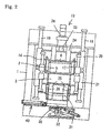
- Fig. 1 is a front view, partly in cross section, of an example of the flaskless molding machine that is applicable to the method of the present invention.
- Fig. 2 shows a view taken along arrows A-A of Fig. 1, where a match plate is clamped and held between a cope flask and a drag flask.
- Fig. 3 is a top view of the molding machine of Fig. 1.
- Fig. 4 is an illustrative sequence of the molding machine of Fig. 1 with a step of injecting molding sand into the cope and drag flasks.
- Figs. 1 to 4 show the flaskless molding machine to implement the molding method of the present invention. The molding machine includes a rectangular machinery mount whose inner chamber includes a station P for defining molding spaces, a sand-supplying station S, and a core setting/mold stripping station W
- The station P, which defines the molding spaces, has two pairs of a
cope flask 2 and adrag flask 3. Each flask defines an opening and has a sand-filling port on its sidewall for supplying molding sand. Although in this embodiment one flask has just one sand-filling port, one or more sand-filling ports may be provided with the one flask. The station P includes ashuttle 4 for carrying in and carrying out amatch plate 5. Both faces of it are formed with patterns, between one of the two pairs of thecope flask 2 and thedrag flask 3, and asqueezing mechanism 9. Thesqueezing mechanism 9 includes anupper squeeze plate 6 and alower squeeze plate 7. They are insertable in and removable from the corresponding openings of the flasks that oppose thematch plate 5 when it is clamped and held between one pair of the core flask and the drag flask. Thesqueeze mechanism 9 is pivotally supported on a supportingshaft 8 that is mounted on the machinery mount such that thesqueeze mechanism 9 can be reversiblely rotated about the supportingshaft 8 in the vertical plane. The range of the rotating or pivoting motion of thesqueezing mechanism 9 is between the vertical position and horizontal position. In the vertical position, a pair of thecope flask 2 and thedrag flask 3 that are clamped and that hold thematch plate 5 therebetween are in their vertical positions. Meanwhile, they are in their horizontal positions at the horizontal position of the rotating motion of thesqueezing mechanism 9. The station P, which defines the molding spaces, also has atransverse cylinder 10 for reversiblely rotating thesqueeze mechanism 9. - The sand-supplying station S includes a sand-supplying
device 11 for filling molding sand into a pair of thecope flask 2 and thedrag flask 3 that have been in the vertical position, by extending thecylinder 10 through the sand-filling ports. - The core setting/mold stripping station W includes mold-
stripping equipment 12 for stripping the resulting upper half-mold and the lower half-mold from the paired cope andflask 2 anddrag flask 3, which are positioned in their horizontal positions and which are stacked such that they contain the upper half-mold and the lower half-mold. The core setting/mold stripping station W also includes arotating mechanism 13 for alternatively and intermittently rotating two pairs of the stackedcope flasks 2 anddrag flasks 3 in the horizontal state, in which one pair of the flasks and another pair of flasks are deposed in a parallel relation on a horizontal level, one at a time, between thesqueezing mechanism 9 and the mold-stripping device 12. Therotating mechanism 13 also can be engaged with eachcope flask 2 to move it up and down. - In each pair of the
cope flask 2 anddrag flask 3 of the two pairs, as shown in Fig. 1 a pair of connectingrods 14 is vertically and slidably suspended from the front and rear sides of thecope flask 2. The lower ends of the connectingrods 14 can be engaged with thedrag flask 3. - Engaging
members 2a are attached to the center positions of the opposed sides of thecope flask 2, whileengaging members 3a are attached to the ends of the opposed sides of thedrag flask 3 when it is in thesqueezing mechanism 9 such that the one pair of thecope flask 2 and thedrag flask 3 can be supported by therotating mechanism 13. For example, eachengaging member rotating mechanism 13. Because the profile of eachengaging member engaging member 37 or 39, it may take, e.g., a concave profile. - As shown in Fig. 1, the
shuttle 4 for carrying the match plate includes aring member 15 that is fitted on the supportingshaft 8 of thesqueezing mechanism 9, and acylinder 16, which is pivotally attached to the sand-supplyingdevice 11. The end of a piston rod of thecylinder 16 is pivotally connected to a portion of thering member 15. Theshuttle 4 also includes a pair ofcantilevered arms 17, the bases of the ends are attached to thering member 15. Theshuttle 4 also includes a suspendedtruck 45 that is laterally movable when thematch plate 5 is placed on it. Thetruck 45 is lowered by a predetermined, relatively short, distance by means of thecope flask 2, while the paired and cantileveredarms 17 are pivoted up and down by a telescopic motion of thecylinder 16 such that thearms 17 are engaged with and disengaged from thetruck 45. Thetruck 45 runs on rails (not shown) that are provided on thecope flask 2 and thedrag flask 3, to carry in and carry out thematch plate 5 between thehorizontal cope flask 2 anddrag flask 3 in thesqueezing mechanism 9. - To move the
arms 17, thecylinder 16 may be replaced with, e.g., a motor, etc. - In the
squeezing mechanism 9, as shown in Fig. 4, a rotatingframe 18 is rotatably fitted to the approximate center portion of the supportingshaft 8, which is mounted on the center of the upper surface of themachinery mount 1. The rotatingframe 18 can thus be reversibly rotated in the vertical plane. The right side of the rotatingframe 18 is provided with a pair of vertical, elongated guidingarms 19. The guidingarms 19 are positioned in the rear and front in relation to each other, to form a predetermined distance therebetween. A reverse-L-shaped upper vertically-movingframe 20 and an L-shaped lower vertically-movingframe 21 are vertically and slidably mounted on and across the upper portions and the lower portions, respectively, of two guidingrods 19, by means of holders, each of which is integrally provided with acorresponding frame frame 20 and the lower vertically-movingframe 21 can be moved close to and away from each other by a telescopic motion of an upwardly-facingcylinder 22 and a downwardly-facingcylinder 23, respectively. Thesecylinders rotating frame 18. - The upper vertically-moving
frame 20 has a plurality ofcylinders 24 for advancing and retracting the upper squeezingplate 6, while the lower vertically-movingframe 21 has a plurality ofcylinders 25 for advancing and retracting the lower squeezingplate 7. The horizontal surface of each squeezingplate flask - In this embodiment, the cylinders for driving the squeezing
plates rotating frame 18. Alternatively, the cylinders may be fixed on the fixed portions. Further, one group of the cylinders of the squeezingplate - In this embodiment, the sand-supplying
device 11, which is mounted on the top of the machinery mount 1 (near the left side in the figure), includes twoaeration tanks 27 so as to separately introduce the molding sand into the copeflask 2 and thedrag flask 3, while the injected molding sand is floated or fluidized ("aeration- injecting process ") by compressed air with a low pressure. Typically, however, just one aeration tank may be used to fill the molding sand into both the copeflask 2 and thedrag flask 3. - The aeration-injecting sand for floating or fluidizing the molding sand using the compressed air with the low pressure is disclosed, in, e.g.,
U.S. Patent No. 6,749,003 B2 , assigned to the applicant of the present application. It was found that the desirable pressures of the low-pressure air are from 0.05 Mpa to 0.18 Mpa. However, a suitable injecting process that can be used for the present invention is not limited to the fluidizing and injecting process. For example, a blowing injecting process using compressed air with a higher pressure may be used in the present invention. Alternatively, the sand-supplyingdevice 11 may be connected to a decompressor (not shown) to be used together with air at a low pressure, i.e., below atmospheric pressure, in either the aeration-injecting process or the blowing-injecting process. - The mold-stripping
device 12 includes a strippingplate 28, which is insertable in and retractable from the overlapped horizontal copeflask 2 and dragflask 3. That strippingplate 28 is attached to the lower end of the piston rod of a downwardly-facingcylinder 29 that is mounted on the roof of themachinery mount 1. The strippingplate 28 can be moved vertically by a telescopic motion of thecylinder 29. Placed intermediately below the strippingplate 28 is a receiving table 30 for receiving an upper half-mold and a lower half-mold to be withdrawn from the copeflask 2 and thedrag flask 3, respectively. Preferably, the receiving table 30 is moved vertically by apantograph 32 that can be extended and retracted by telescopic motions of acylinder 31. Thepantograph 32 may be replaced with a common lift table that is moved by a suitable cylinder. However, using thepantograph 32 as a driver for elevationally moving the receivingdevice 30, as in this embodiment, requires no pit for receiving the driver on the floor level on which the molding machine is installed (see Fig. 2). - In the
rotating mechanism 13, a vertically elongated,rotary shaft 33 is horizontally and rotatably mounted on themachinery mount 1. The upper end of therotary shaft 33 is connected to the output of amotor 34, which is mounted on the top of themachinery mount 1. Therotary shaft 33 can be reversibly turned within a turning range of 180° by driving themotor 34. Themotor 34 may be replaced with a suitable cylinder. - The turning range of 180° of the
rotary shaft 33 is just an example of its possible turning ranges for transferring the resulting mold from the on-site position where the mold is formed to the mold-strippingequipment 12 by the rotatingmechanism 13. Because this turning range is defined and based on the site where the mold-strippingequipment 12 is installed, it is not limited to the 180°. Theequipment 12 may be installed in any site, based on the desirable turning range of the shaft. - The upper portion of the
rotary shaft 33 has a supportingmember 35 from which two pairs of guidingrods 36 are suspended. They are arranged in a back and front relationship to form a predetermined distance therebetween such that they are opposed to each other across therotary shaft 33 that is centered therebetween. The upper engaging member 37 is vertically and slidably fitted on each pair of the guidingrods 36 to engage the engagingmembers 2a. The upper engaging member 37 is attached to the distal end of the piston rod of thecylinder 38 that is mounted on therotary shaft 33. The upper engaging member 37 can thus be vertically moved by a telescopic motion of thecylinder 38. The lower ends of the two pairs of the guidingrods 36 are attached to a lower engagingmember 39, which that can be engaged to the engagingmembers 3a of the twodrag flasks 3. - One of the functions of a
mold ejector 40 is to push out the upper and lower half-molds, which are drawn from the copeflask 2 and thedrag flask 3, from the receiving table 30. - With the molding method of the present invention, first, the
match plate 5 is carried in between the horizontal cope anddrag flasks cylinder 16 of theshuttle 4. - The cope
flask 2 and thedrag flask 3 are then moved closer to each other by means of the upper and lower vertically-movingframes cylinder 22 and the downwardly-facingcylinder 23 of the squeezingmechanism 9. The copeflask 2 and thedrag flask 3 are then clamped, and hold thematch plate 5 therebetween, while the clusteredcylinders upper squeeze plate 6 and thelower squeeze plate 7 to be inserted in the openings of the copeflask 2 and thedrag flask 3 by a predetermined length, to define an upper molding space and a lower molding space. As used herein, the volume of each molding space in this state refers to the initial volume. The predetermined stroke length of the extending motion of the clusteredcylinder upper squeeze plate 6 or thelower squeeze plate 7 corresponds to the initial volume of the molding space to be defined. In addition, the clusteredcylinders - When the upper and lower molding spaces, each of which has the initial volume, are defined, the
cylinder 10 is extended to rotate thesqueeze mechanism 9 clockwise about the supportingshaft 8 such that the paired cope anddrag flasks match plate 5, are positioned at their vertical positions while the sand-filling ports are raised. - The raised sand-filling ports abut the lower ends of the two
aeration tanks 27 of the sand-supplying device 11 (see Fig. 4). - If the height of the cope
flask 2 is the same as that of thedrag flask 3, the paired molding spaces may be simultaneously defined. Alternatively, if the copeflask 2 and thedrag flask 3 have different heights, two molding spaces may be separately defined at different times. - In the sand-injecting station S, the sand-supplying
device 11 then injects the molding sand into the paired upper and lower molding spaces through the sand-filling ports (a first injection step), using any suitable injecting method, such as aeration injecting with compressed air that has a low pressure, namely, below atmospheric pressure. - The clustered
cylinders lower squeeze plates flask 6 and dragflask 7. Therefore, the volume of each molding space is increased from its initial volume. - The sand-supplying
device 11 then re-injects the molding sand into the increased upper and lower molding spaces through the sand-filling ports (a second injection step). The paired copeflask 2 and dragflask 3, and thematch plate 5, are returned to their horizontal positions. During this movement, the clusteredcylinders plate 6 and lower squeezingplate 7 move into the corresponding flasks to squeeze the molding sand within the two molding spaces. - Accordingly, the molding sand is squeezed, followed by the two steps of injecting the molding sand. During them the first injecting step is carried out when each molding space has the initial volume. The second injecting step is applied to the increased molding spaces. The two steps of injecting the molding sand result in the increased hardness of the mold. This remarkable effect may be seen at the portions of the molds near the openings of the paired cope
flask 2 and dragflask 3 that contain the molds. - In the two steps of injecting the molding sand in this embodiment, the first injecting step is applied to the molding spaces, each of which has the initial volume. The second injecting step is applied after the increased volumes of the molding spaces, caused by retracting the upper and
lower squeeze plates - About the beginning of the second injecting step, however, it is not necessary to wait until the increased volumes of the old spaces have been completed. For example, followed by the first injecting step, while the upper and
lower squeeze plates - Following the two steps of injecting the molding sand, the upwardly-facing
cylinder 22 and the downwardly-facingcylinder 23 are extended such that the upper vertically-movingframe 20 and the lower vertically-movingframe 21 are spaced apart from each other. - In the core setting / mold drawing station W, the cope
flask 2, which contains the half-mold, which is produced by squeezing the molding sand, is lifted by means of the upper engaging member 37 to separate it from thematch plate 5 by extending thecylinder 38 of therotating mechanism 13. Meanwhile, thedrag flask 3 is disposed on the lower engagingmember 39 of the rotatingmember 13. Thematch plate 5 is then carried out from between the copeflask 2 and thedrag flask 3 by means of the pairedarms 17, by retracting thecylinder 16. - The
motor 34 of therotating mechanism 13 is driven to turn therotary shaft 33 in a predetermined range such that the pairedupper flask 2 and dragflask 3, each of which contains a mold, are transferred to the mold-strippingequipment 12. A core may then be disposed in each mold, if necessary. Thecylinder 38 is then retracted to lower the copeflask 2 that contains the mold by means of the engaging member 37 such that the copeflask 2 and thedrag flask 3 are stacked. - The
cylinder 31 of the mold-strippingequipment 12 is then extended to rise on the receiving table 30 such that the copeflask 2 and dragflask 3 that contain the molds are disposed on the receiving table 30. Thecylinder 29 of the mold-strippingequipment 12 is extended such that the strippingplate 28 contacts the half-mold within the copeflask 2. Thecylinder 31 is then retracted to lower the strippingplate 28 and the receiving table 30 in a cooperative relationship to strip the half-molds from the paired copeflask 2 anddrag flasks 3. Thecylinder 31 is then retracted at the level at which the half-molds are to be ejected such that theejector 40 is pushed off the paired upper and lower half-molds from the receiving table 40. - In the above-described processes, it is desirable that a core be put in each formed half-mold, if so needed. If so, a core is put in each preceding formed half-mold before the cope
flask 2 and thedrag flask 3, each containing a new formed half-mold, are rotated and thus transferred to the mold-strippingequipment 12. The paired copeflask 2 and dragflask 3 are then stacked on each other to push out the half-molds in them, as discussed above. - Although the present invention has been described with reference to the illustrative embodiments, they are not intended to limit the present invention. It will be apparent that various modifications can be made without departing from the spirit of the present invention, as set forth in the appended claims.
- For example, although the squeezing means are shown as the upper and lower squeezing
plates
Claims (12)
- A method for molding stacked upper and lower molds with a flaskless molding machine that includes a cope flask and a drag flask, each flask defining an opening and having at least one sand-filling port for injecting molding sand into the opening, a match plate having upper and lower patterns on top and bottom faces corresponding to the cope and drag flasks, and upper and lower squeezing members, each squeezing member being insertable into and retractable from the corresponding opening of the corresponding flask for squeezing the molding sand to be molded,
said method being characterized in comprising the steps of :defining upper and lower molding spaces by inserting the upper and lower squeezing members into the respective openings of the respective flasks opposed to the respective patterns of the match plate such that the upper molding space is defined by the cope flask, the top face of the match plate, and the upper squeezing member, and the lower molding space is defined by the drag flask, the bottom face of the match plate, and the lower squeezing member, wherein each molding space has an initial volume;a first injection of the molding sand into each molding space that has the initial volume, from the sand-filling ports;increasing a volume in each molding space above the initial volume by retracting the upper and lower squeezing members by a predetermined length;a second injection of the molding sand into each molding space that has the increased volume from the sand-filling ports;advancing the upper and lower squeezing members, following by the second injecting step, to squeeze the molding sand within the upper and lower molding spaces to mold stacked upper and lower molds; andremoving the resulting upper and lower molds from the cope and drag flasks. - The method of claim 1, wherein said second injection of the molding sand is begin after said step of increasing the volume in each molding space has been completed and thus the desired volume in each molding space has been reached.
- The method of claim 1, wherein said second injection of the molding sand is applied while the upper and lower squeezing members are still retracted in said step of increasing the volume in each molding space such that said second injection of the molding sand is begun before the desired volume has been reached in said step of increasing the volume in each molding space.
- The method of any one of claims 1, 2, and 3, wherein the cope and drag flasks are in their vertical positions during said steps of the first and second injections of the molding sand, whereas they are in their horizontal positions during said step of removing the resulting molds.
- The method of claim 4, wherein said step of defining the molding spaces is carried out while the cope and drag flasks are returning from their horizontal positions to their vertical positions, in which said step of removing the molds has been completed.
- The method of any one of claims 1 to 5, wherein each of the upper and lower squeeze members is a squeezing plate or squeezing foot.
- A method for molding stacked upper and lower molds with a flaskless molding machine that includes a cope flask and a drag flask, where each flask defines an opening and has at least one sand-filling port for injecting molding sand into the opening, wherein a match plate has upper and lower patterns on top and bottom faces corresponding to the cope and drag flasks, wherein there are upper and lower squeezing members, each squeezing member being insertable into and retractable from the corresponding opening of the corresponding flask for squeezing the molding sand to be molded,
said method being characterized in comprising the steps of:clamping and holding the match plate between the cope flask and the drag flask, wherein the cope and drag flasks are in their horizontal positions;defining upper and lower molding spaces by inserting the upper and lower squeezing members into the respective openings of the respective flasks opposed to the respective patterns of the match plate such that the upper molding space is defined by the cope flask, the top face of the match plate, and the upper squeezing member, and the lower molding space is defined by the drag flask, the bottom face of the match plate, and the lower squeezing member, wherein each molding space has an initial volume;turning the cope and drag flasks and the match plate to their vertical positions in unison;a first injection of the molding sand into each molding space that has the initial volume, from the sand-filling ports;increasing a volume in each molding space above the initial volume by retracting the upper and lower squeezing members by a predetermined length;a second injection of the molding sand into each molding space that has the increased volume, from the sand-filling ports; advancing the upper and lower squeezing members to squeeze the molding sand within the upper and lower molding spaces, while returning the cope and drag flasks and the match plate to their horizontal positions in unison;removing the match plate from the cope and drag flasks, wherein each flask contains a mold;stacking the cope flask and the drag flask; andremoving the molds from the stacked cope and drag flasks. - The method of claim 7, further comprising the step of setting a core in each mold prior to said step of stacking the cope flask and the drag flask.
- The method of claim 7 or 8, wherein said second injection of the molding sand is begun after said step of increasing the volume in each mold space has been completed and thus the desired volume in each molding space has been reached.
- The method of claim 7 or 8, wherein said second injection is applied while the upper and lower squeezing members are still retracted in said step of increasing the volume in each molding space such that said second injection of the molding sand is begun before said step of increasing the volume in each molding space has been completed by reaching the desired volume.
- The method of any one of claims 7 to 10, wherein said step of defining the molding spaces is carried out while the cope and drag flasks, and the match plate, are in their horizontal positions;
said step of turning the cope and drag flasks, and the match plate, to their vertical positions in unison causes the sand-filling ports for injecting the molding sand to move upward;
said cope and drag flasks being in their vertical positions during said steps of the first and second injections of the molding sand; and
said cope and drag flasks being in their horizontal positions during said step of removing the molds. - The method of any one of claims 7 to 11, wherein each of the upper and lower squeeze members may be a squeezing plate or squeezing foot.
Priority Applications (1)
| Application Number | Priority Date | Filing Date | Title |
|---|---|---|---|
| PL06746214T PL1880781T3 (en) | 2005-05-10 | 2006-05-10 | Flaskless molding method |
Applications Claiming Priority (2)
| Application Number | Priority Date | Filing Date | Title |
|---|---|---|---|
| JP2005137127A JP4374619B2 (en) | 2005-05-10 | 2005-05-10 | Molding method for upper and lower molds without casting frames |
| PCT/JP2006/309400 WO2006121076A1 (en) | 2005-05-10 | 2006-05-10 | Flaskless molding method |
Publications (3)
| Publication Number | Publication Date |
|---|---|
| EP1880781A1 true EP1880781A1 (en) | 2008-01-23 |
| EP1880781A4 EP1880781A4 (en) | 2009-07-22 |
| EP1880781B1 EP1880781B1 (en) | 2011-03-16 |
Family
ID=37396583
Family Applications (1)
| Application Number | Title | Priority Date | Filing Date |
|---|---|---|---|
| EP06746214A Active EP1880781B1 (en) | 2005-05-10 | 2006-05-10 | Flaskless molding method |
Country Status (10)
| Country | Link |
|---|---|
| US (1) | US8056605B2 (en) |
| EP (1) | EP1880781B1 (en) |
| JP (1) | JP4374619B2 (en) |
| KR (1) | KR101135781B1 (en) |
| CN (1) | CN101175589B (en) |
| BR (1) | BRPI0608786B1 (en) |
| DE (1) | DE602006020716D1 (en) |
| DK (1) | DK1880781T3 (en) |
| PL (1) | PL1880781T3 (en) |
| WO (1) | WO2006121076A1 (en) |
Cited By (1)
| Publication number | Priority date | Publication date | Assignee | Title |
|---|---|---|---|---|
| EP2777844A4 (en) * | 2012-01-20 | 2016-04-13 | Sintokogio Ltd | Flaskless mold making device, flaskless mold making method, and sand receiving device |
Families Citing this family (12)
| Publication number | Priority date | Publication date | Assignee | Title |
|---|---|---|---|---|
| US7823621B2 (en) * | 2005-06-13 | 2010-11-02 | Sintokogio, Ltd. | Method for making flaskless upper and lower molds, an apparatus therefor, and a method for placing a core |
| EP1857200B1 (en) * | 2007-05-25 | 2010-10-06 | Sintokogio, Ltd. | Flaskless molding machine |
| BR112012028034B1 (en) * | 2010-07-23 | 2017-12-19 | Sintokogio, Ltd. | A METHOD OF MOLDING WITHOUT BOXES OF MOLDING AND A MOLDING MACHINE WITHOUT BOXES OF MOLDING |
| JP5510823B2 (en) * | 2010-07-23 | 2014-06-04 | 新東工業株式会社 | Unframed mold making method and unframed mold making apparatus |
| JP5594593B2 (en) * | 2010-10-06 | 2014-09-24 | 新東工業株式会社 | Punched frame mold making apparatus and punched frame mold making method |
| CN103658523B (en) * | 2013-12-27 | 2015-07-15 | 山西宇达集团有限公司 | Process method for producing large size sculpture through resin sand removable-flask moulding |
| CN104841890B (en) * | 2015-04-06 | 2016-08-24 | 林杭 | A kind of branch mailbox moulding machine |
| KR101652411B1 (en) * | 2016-02-24 | 2016-08-30 | (주)중앙 | mold manufacturing equipment with transmission means capable of preventing damage of sand mold |
| CN106734948A (en) * | 2016-11-30 | 2017-05-31 | 蓝强 | A kind of two-sided casting die |
| CN106734969B (en) * | 2016-12-25 | 2018-07-03 | 重庆市永川区泰兴机械厂 | Pressing type stripper apparatus |
| CN108296455A (en) * | 2017-10-31 | 2018-07-20 | 柳州市柳晶科技股份有限公司 | Precoated sand core shooter |
| CN107999708A (en) * | 2017-12-12 | 2018-05-08 | 严传玉 | A kind of sand mold manufacturing machine |
Citations (3)
| Publication number | Priority date | Publication date | Assignee | Title |
|---|---|---|---|---|
| EP0098405A1 (en) * | 1982-07-06 | 1984-01-18 | Heidelberger Druckmaschinen Aktiengesellschaft | Method of producing large size green sand moulding parts (mould area 1-3 m2) for pouring into flaskless moulds |
| US4463794A (en) * | 1979-09-17 | 1984-08-07 | Kabushiki Kaisha Toyoda Jidoshokki Seisakusho | Apparatus for producing containerless sand molds |
| JP2005007439A (en) * | 2003-06-19 | 2005-01-13 | Sintokogio Ltd | Method for molding mold |
Family Cites Families (7)
| Publication number | Priority date | Publication date | Assignee | Title |
|---|---|---|---|---|
| USRE28735E (en) * | 1972-03-10 | 1976-03-16 | Pettibone Corporation | Cyclicly-operable machine adapted to produce and assemble cope and drag mold parts |
| JPH0673514B2 (en) | 1985-07-16 | 1994-09-21 | 松下電器産業株式会社 | Dishwashing method |
| ES2182481T3 (en) * | 1999-02-23 | 2003-03-01 | Disa Ind As | MACHINE TO PRODUCE MOLDS WITHOUT MOLDING BOX. |
| EP1149646B1 (en) * | 1999-11-04 | 2011-05-18 | Sintokogio, Ltd. | Molding device and molding method for sand mold |
| JP2003103345A (en) * | 2001-09-27 | 2003-04-08 | Hideo Hamada | Frameless mold forming machine and pattern plate used therefor |
| DE602004030478D1 (en) * | 2003-12-18 | 2011-01-20 | Sintokogio Ltd | METHOD AND DEVICE FOR THE CASE-FREE SHAPING OF A TOP AND LOWER BOX AND METHOD FOR REPLACING A TURN PLATE |
| EA008842B1 (en) * | 2004-03-18 | 2007-08-31 | Синтокогио, Лтд. | Method and device for forming molding flask-less, upper and lower molds |
-
2005
- 2005-05-10 JP JP2005137127A patent/JP4374619B2/en active Active
-
2006
- 2006-05-10 BR BRPI0608786-8A patent/BRPI0608786B1/en active IP Right Grant
- 2006-05-10 DE DE602006020716T patent/DE602006020716D1/en active Active
- 2006-05-10 CN CN2006800161083A patent/CN101175589B/en active Active
- 2006-05-10 KR KR1020077028619A patent/KR101135781B1/en active IP Right Grant
- 2006-05-10 EP EP06746214A patent/EP1880781B1/en active Active
- 2006-05-10 PL PL06746214T patent/PL1880781T3/en unknown
- 2006-05-10 US US11/913,624 patent/US8056605B2/en active Active
- 2006-05-10 DK DK06746214.3T patent/DK1880781T3/en active
- 2006-05-10 WO PCT/JP2006/309400 patent/WO2006121076A1/en active Application Filing
Patent Citations (3)
| Publication number | Priority date | Publication date | Assignee | Title |
|---|---|---|---|---|
| US4463794A (en) * | 1979-09-17 | 1984-08-07 | Kabushiki Kaisha Toyoda Jidoshokki Seisakusho | Apparatus for producing containerless sand molds |
| EP0098405A1 (en) * | 1982-07-06 | 1984-01-18 | Heidelberger Druckmaschinen Aktiengesellschaft | Method of producing large size green sand moulding parts (mould area 1-3 m2) for pouring into flaskless moulds |
| JP2005007439A (en) * | 2003-06-19 | 2005-01-13 | Sintokogio Ltd | Method for molding mold |
Non-Patent Citations (1)
| Title |
|---|
| See also references of WO2006121076A1 * |
Cited By (1)
| Publication number | Priority date | Publication date | Assignee | Title |
|---|---|---|---|---|
| EP2777844A4 (en) * | 2012-01-20 | 2016-04-13 | Sintokogio Ltd | Flaskless mold making device, flaskless mold making method, and sand receiving device |
Also Published As
| Publication number | Publication date |
|---|---|
| CN101175589B (en) | 2010-05-19 |
| DK1880781T3 (en) | 2011-06-20 |
| BRPI0608786B1 (en) | 2015-02-10 |
| JP4374619B2 (en) | 2009-12-02 |
| KR101135781B1 (en) | 2012-04-16 |
| EP1880781A4 (en) | 2009-07-22 |
| DE602006020716D1 (en) | 2011-04-28 |
| EP1880781B1 (en) | 2011-03-16 |
| US20090078389A1 (en) | 2009-03-26 |
| CN101175589A (en) | 2008-05-07 |
| JP2006315012A (en) | 2006-11-24 |
| WO2006121076A1 (en) | 2006-11-16 |
| BRPI0608786A2 (en) | 2010-01-26 |
| PL1880781T3 (en) | 2011-07-29 |
| KR20080009320A (en) | 2008-01-28 |
| US8056605B2 (en) | 2011-11-15 |
Similar Documents
| Publication | Publication Date | Title |
|---|---|---|
| US8056605B2 (en) | Flaskless molding method | |
| KR101600981B1 (en) | Simultaneous molding method, and ejection molding device | |
| TW555600B (en) | Die molding machine and pattern carrier | |
| EP0468355B1 (en) | Flaskless molding machine | |
| US10875086B2 (en) | Molding flask for a molding machine and a molding process using the molding flask | |
| US7654302B2 (en) | Method and apparatus for molding an upper and a lower mold having no flask, and a method for replacing a match plate used therefor | |
| EP1897634B1 (en) | Apparatus for molding molding flask-free upper casting mold and lower casting mold | |
| EP1935533B1 (en) | Molding machine | |
| US7654303B2 (en) | Method and apparatus for molding an upper and a lower mold having no flask | |
| JP5168743B2 (en) | Simultaneous mold making method and blank frame mold making apparatus | |
| EP1857200B1 (en) | Flaskless molding machine | |
| EP1878518A1 (en) | A method of changing a match plate in a flaskless molding apparatus for an upper mold and a lower mold | |
| CN210587041U (en) | Novel molding machine of high-efficient easy maintenance | |
| KR20090101466A (en) | Molding machine and molding method | |
| RU2354491C2 (en) | Casting-box for moulding machine and moulding method using casting-box |
Legal Events
| Date | Code | Title | Description |
|---|---|---|---|
| PUAI | Public reference made under article 153(3) epc to a published international application that has entered the european phase |
Free format text: ORIGINAL CODE: 0009012 |
|
| 17P | Request for examination filed |
Effective date: 20071105 |
|
| AK | Designated contracting states |
Kind code of ref document: A1 Designated state(s): AT BE BG CH CY CZ DE DK EE ES FI FR GB GR HU IE IS IT LI LT LU LV MC NL PL PT RO SE SI SK TR |
|
| DAX | Request for extension of the european patent (deleted) | ||
| A4 | Supplementary search report drawn up and despatched |
Effective date: 20090622 |
|
| 17Q | First examination report despatched |
Effective date: 20091029 |
|
| RAP1 | Party data changed (applicant data changed or rights of an application transferred) |
Owner name: SINTOKOGIO, LTD. |
|
| GRAP | Despatch of communication of intention to grant a patent |
Free format text: ORIGINAL CODE: EPIDOSNIGR1 |
|
| GRAS | Grant fee paid |
Free format text: ORIGINAL CODE: EPIDOSNIGR3 |
|
| GRAA | (expected) grant |
Free format text: ORIGINAL CODE: 0009210 |
|
| AK | Designated contracting states |
Kind code of ref document: B1 Designated state(s): AT BE BG CH CY CZ DE DK EE ES FI FR GB GR HU IE IS IT LI LT LU LV MC NL PL PT RO SE SI SK TR |
|
| REG | Reference to a national code |
Ref country code: GB Ref legal event code: FG4D |
|
| REG | Reference to a national code |
Ref country code: CH Ref legal event code: EP |
|
| REG | Reference to a national code |
Ref country code: IE Ref legal event code: FG4D |
|
| REF | Corresponds to: |
Ref document number: 602006020716 Country of ref document: DE Date of ref document: 20110428 Kind code of ref document: P |
|
| REG | Reference to a national code |
Ref country code: DE Ref legal event code: R096 Ref document number: 602006020716 Country of ref document: DE Effective date: 20110428 |
|
| REG | Reference to a national code |
Ref country code: DK Ref legal event code: T3 |
|
| REG | Reference to a national code |
Ref country code: NL Ref legal event code: VDEP Effective date: 20110316 |
|
| PG25 | Lapsed in a contracting state [announced via postgrant information from national office to epo] |
Ref country code: SE Free format text: LAPSE BECAUSE OF FAILURE TO SUBMIT A TRANSLATION OF THE DESCRIPTION OR TO PAY THE FEE WITHIN THE PRESCRIBED TIME-LIMIT Effective date: 20110316 Ref country code: GR Free format text: LAPSE BECAUSE OF FAILURE TO SUBMIT A TRANSLATION OF THE DESCRIPTION OR TO PAY THE FEE WITHIN THE PRESCRIBED TIME-LIMIT Effective date: 20110617 Ref country code: LV Free format text: LAPSE BECAUSE OF FAILURE TO SUBMIT A TRANSLATION OF THE DESCRIPTION OR TO PAY THE FEE WITHIN THE PRESCRIBED TIME-LIMIT Effective date: 20110316 Ref country code: ES Free format text: LAPSE BECAUSE OF FAILURE TO SUBMIT A TRANSLATION OF THE DESCRIPTION OR TO PAY THE FEE WITHIN THE PRESCRIBED TIME-LIMIT Effective date: 20110627 Ref country code: LT Free format text: LAPSE BECAUSE OF FAILURE TO SUBMIT A TRANSLATION OF THE DESCRIPTION OR TO PAY THE FEE WITHIN THE PRESCRIBED TIME-LIMIT Effective date: 20110316 |
|
| REG | Reference to a national code |
Ref country code: PL Ref legal event code: T3 |
|
| LTIE | Lt: invalidation of european patent or patent extension |
Effective date: 20110316 |
|
| PG25 | Lapsed in a contracting state [announced via postgrant information from national office to epo] |
Ref country code: SI Free format text: LAPSE BECAUSE OF FAILURE TO SUBMIT A TRANSLATION OF THE DESCRIPTION OR TO PAY THE FEE WITHIN THE PRESCRIBED TIME-LIMIT Effective date: 20110316 Ref country code: BG Free format text: LAPSE BECAUSE OF FAILURE TO SUBMIT A TRANSLATION OF THE DESCRIPTION OR TO PAY THE FEE WITHIN THE PRESCRIBED TIME-LIMIT Effective date: 20110616 Ref country code: AT Free format text: LAPSE BECAUSE OF FAILURE TO SUBMIT A TRANSLATION OF THE DESCRIPTION OR TO PAY THE FEE WITHIN THE PRESCRIBED TIME-LIMIT Effective date: 20110316 Ref country code: FI Free format text: LAPSE BECAUSE OF FAILURE TO SUBMIT A TRANSLATION OF THE DESCRIPTION OR TO PAY THE FEE WITHIN THE PRESCRIBED TIME-LIMIT Effective date: 20110316 Ref country code: CY Free format text: LAPSE BECAUSE OF FAILURE TO SUBMIT A TRANSLATION OF THE DESCRIPTION OR TO PAY THE FEE WITHIN THE PRESCRIBED TIME-LIMIT Effective date: 20110316 |
|
| PG25 | Lapsed in a contracting state [announced via postgrant information from national office to epo] |
Ref country code: BE Free format text: LAPSE BECAUSE OF FAILURE TO SUBMIT A TRANSLATION OF THE DESCRIPTION OR TO PAY THE FEE WITHIN THE PRESCRIBED TIME-LIMIT Effective date: 20110316 |
|
| PG25 | Lapsed in a contracting state [announced via postgrant information from national office to epo] |
Ref country code: EE Free format text: LAPSE BECAUSE OF FAILURE TO SUBMIT A TRANSLATION OF THE DESCRIPTION OR TO PAY THE FEE WITHIN THE PRESCRIBED TIME-LIMIT Effective date: 20110316 Ref country code: PT Free format text: LAPSE BECAUSE OF FAILURE TO SUBMIT A TRANSLATION OF THE DESCRIPTION OR TO PAY THE FEE WITHIN THE PRESCRIBED TIME-LIMIT Effective date: 20110718 |
|
| PG25 | Lapsed in a contracting state [announced via postgrant information from national office to epo] |
Ref country code: IS Free format text: LAPSE BECAUSE OF FAILURE TO SUBMIT A TRANSLATION OF THE DESCRIPTION OR TO PAY THE FEE WITHIN THE PRESCRIBED TIME-LIMIT Effective date: 20110716 Ref country code: RO Free format text: LAPSE BECAUSE OF FAILURE TO SUBMIT A TRANSLATION OF THE DESCRIPTION OR TO PAY THE FEE WITHIN THE PRESCRIBED TIME-LIMIT Effective date: 20110316 Ref country code: SK Free format text: LAPSE BECAUSE OF FAILURE TO SUBMIT A TRANSLATION OF THE DESCRIPTION OR TO PAY THE FEE WITHIN THE PRESCRIBED TIME-LIMIT Effective date: 20110316 |
|
| PG25 | Lapsed in a contracting state [announced via postgrant information from national office to epo] |
Ref country code: MC Free format text: LAPSE BECAUSE OF NON-PAYMENT OF DUE FEES Effective date: 20110531 Ref country code: NL Free format text: LAPSE BECAUSE OF FAILURE TO SUBMIT A TRANSLATION OF THE DESCRIPTION OR TO PAY THE FEE WITHIN THE PRESCRIBED TIME-LIMIT Effective date: 20110316 |
|
| REG | Reference to a national code |
Ref country code: CH Ref legal event code: PL |
|
| PLBE | No opposition filed within time limit |
Free format text: ORIGINAL CODE: 0009261 |
|
| STAA | Information on the status of an ep patent application or granted ep patent |
Free format text: STATUS: NO OPPOSITION FILED WITHIN TIME LIMIT |
|
| PG25 | Lapsed in a contracting state [announced via postgrant information from national office to epo] |
Ref country code: LI Free format text: LAPSE BECAUSE OF NON-PAYMENT OF DUE FEES Effective date: 20110531 Ref country code: CH Free format text: LAPSE BECAUSE OF NON-PAYMENT OF DUE FEES Effective date: 20110531 |
|
| REG | Reference to a national code |
Ref country code: FR Ref legal event code: ST Effective date: 20120131 |
|
| 26N | No opposition filed |
Effective date: 20111219 |
|
| GBPC | Gb: european patent ceased through non-payment of renewal fee |
Effective date: 20110616 |
|
| REG | Reference to a national code |
Ref country code: IE Ref legal event code: MM4A |
|
| REG | Reference to a national code |
Ref country code: DE Ref legal event code: R097 Ref document number: 602006020716 Country of ref document: DE Effective date: 20111219 |
|
| PG25 | Lapsed in a contracting state [announced via postgrant information from national office to epo] |
Ref country code: IE Free format text: LAPSE BECAUSE OF NON-PAYMENT OF DUE FEES Effective date: 20110510 Ref country code: FR Free format text: LAPSE BECAUSE OF NON-PAYMENT OF DUE FEES Effective date: 20110531 |
|
| PG25 | Lapsed in a contracting state [announced via postgrant information from national office to epo] |
Ref country code: IT Free format text: LAPSE BECAUSE OF FAILURE TO SUBMIT A TRANSLATION OF THE DESCRIPTION OR TO PAY THE FEE WITHIN THE PRESCRIBED TIME-LIMIT Effective date: 20110316 |
|
| PG25 | Lapsed in a contracting state [announced via postgrant information from national office to epo] |
Ref country code: GB Free format text: LAPSE BECAUSE OF NON-PAYMENT OF DUE FEES Effective date: 20110616 |
|
| PG25 | Lapsed in a contracting state [announced via postgrant information from national office to epo] |
Ref country code: LU Free format text: LAPSE BECAUSE OF NON-PAYMENT OF DUE FEES Effective date: 20110510 |
|
| PG25 | Lapsed in a contracting state [announced via postgrant information from national office to epo] |
Ref country code: HU Free format text: LAPSE BECAUSE OF FAILURE TO SUBMIT A TRANSLATION OF THE DESCRIPTION OR TO PAY THE FEE WITHIN THE PRESCRIBED TIME-LIMIT Effective date: 20110316 |
|
| PGFP | Annual fee paid to national office [announced via postgrant information from national office to epo] |
Ref country code: DK Payment date: 20230524 Year of fee payment: 18 Ref country code: DE Payment date: 20230519 Year of fee payment: 18 Ref country code: CZ Payment date: 20230502 Year of fee payment: 18 |
|
| PGFP | Annual fee paid to national office [announced via postgrant information from national office to epo] |
Ref country code: TR Payment date: 20230508 Year of fee payment: 18 Ref country code: PL Payment date: 20230428 Year of fee payment: 18 |