EP1879374A1 - Image processing apparatus and method - Google Patents
Image processing apparatus and method Download PDFInfo
- Publication number
- EP1879374A1 EP1879374A1 EP07109288A EP07109288A EP1879374A1 EP 1879374 A1 EP1879374 A1 EP 1879374A1 EP 07109288 A EP07109288 A EP 07109288A EP 07109288 A EP07109288 A EP 07109288A EP 1879374 A1 EP1879374 A1 EP 1879374A1
- Authority
- EP
- European Patent Office
- Prior art keywords
- image processing
- image
- pixels
- processing apparatus
- candidate
- Prior art date
- Legal status (The legal status is an assumption and is not a legal conclusion. Google has not performed a legal analysis and makes no representation as to the accuracy of the status listed.)
- Granted
Links
Images





Classifications
-
- H—ELECTRICITY
- H04—ELECTRIC COMMUNICATION TECHNIQUE
- H04N—PICTORIAL COMMUNICATION, e.g. TELEVISION
- H04N1/00—Scanning, transmission or reproduction of documents or the like, e.g. facsimile transmission; Details thereof
- H04N1/38—Circuits or arrangements for blanking or otherwise eliminating unwanted parts of pictures
-
- H—ELECTRICITY
- H04—ELECTRIC COMMUNICATION TECHNIQUE
- H04N—PICTORIAL COMMUNICATION, e.g. TELEVISION
- H04N1/00—Scanning, transmission or reproduction of documents or the like, e.g. facsimile transmission; Details thereof
- H04N1/387—Composing, repositioning or otherwise geometrically modifying originals
-
- G—PHYSICS
- G06—COMPUTING OR CALCULATING; COUNTING
- G06T—IMAGE DATA PROCESSING OR GENERATION, IN GENERAL
- G06T7/00—Image analysis
- G06T7/10—Segmentation; Edge detection
- G06T7/11—Region-based segmentation
Definitions
- the present invention relates to an image processing apparatus and an image processing method, and more particularly, to an image processing apparatus and an image processing method, which are capable of removing a certain region of an input image or dividing a certain portion of the input image with a reduced computation and a high applicability.
- An image processing apparatus such as a copier, a multifunction copier or the like, incorporates scanning an object to generate its image as a copy of the object, processing the generated image, and printing the processed image on a record medium such as a paper. Such image processing may be performed by a separate image processing apparatus.
- U.S. Patent No. 6,330,050 discloses a conventional technique which estimates heights of portions on coordinates of an input image from a scan plane, and corrects a distortion of the image based on the estimated heights.
- this technique has a problem in that a great deal of computation is required to estimate the heights and this technique is applicable only when the folding line is parallel to a scanner, that is, is perpendicular to a main scan direction.
- the present invention provides an image processing apparatus and an image processing method, which are capable of removing a certain region of an input image or dividing a certain portion of the input image with a reduced computation and a high applicability.
- an image processing method including determining one or more candidate pixels having variation of brightness in a first direction, among a plurality of pixels constituting an input image, the variation of brightness exceeding a first reference value, determining a certain region in which a total number of candidate pixels existing in a row of pixels in a second direction different from the first direction exceeds a second reference value, and generating an output image free from the determined certain region.
- the first and second directions may be horizontal and vertical directions of the input image, respectively.
- the first reference value may be twice the variation of brightness in the vertical direction.
- the second reference value may be equal to 80% of the total number of corresponding pixels in the row of pixels.
- the determining of the one or more candidate pixels may further include determining a candidate pixel block comprising at least one candidate pixel among a plurality of 9*9 pixel blocks constituting the input image, and the determining of the certain region comprises determining the certain region in a unit of the candidate pixel block.
- the image processing method may further include substituting the candidate pixel block for at least one pixel block arranged in the horizontal direction from the candidate pixel block.
- the image processing method may further include generating the input image by scanning a copy object.
- the image processing method may further include printing the generated output image on a record medium.
- the generating of the output image comprises dividing the input image into two output images on the basis of the determined certain region.
- an image processing apparatus including an image processing part that determines one or more candidate pixels having variation of brightness in a first direction, among a plurality of pixels constituting an input image, the variation of brightness exceeding a first reference value, and a certain region in which a total number of candidate pixels existing in a row of pixels in a second direction different from the first direction exceeds a second reference value, and generates an output image free from the determined certain region.
- the first and second directions may be horizontal and vertical directions of the input image, respectively.
- the first reference value may be twice the variation of brightness in the vertical direction.
- the second reference value may be equal to 80% of the total number of corresponding pixels in the row of pixels.
- the image processing part may determine a candidate pixel block comprising at least one candidate pixel among a plurality of 9*9 pixel blocks constituting the input image, and determines the certain region in a unit of candidate pixel block.
- the image processing part may substitute the candidate pixel block for at least one pixel block arranged in the horizontal direction from the candidate pixel block.
- the image processing apparatus may further include a scanning part that generates the input image by scanning a copy object.
- the image processing apparatus may further include a printing part that prints the generated output image on a record medium.
- the image processing part may generate the output image by dividing the input image into two output images on the basis of the determined certain region.
- a computer readable recording medium to perform a method, the method including determining one or more candidate pixels having variation of brightness in a first direction, among a plurality of pixels constituting an input image, the variation of brightness exceeding a first reference value; determining a certain region in which a total number of candidate pixels existing in a row of pixels in a second direction different from the first direction exceeds a second reference value; and generating an output image free from the determined certain region.
- an image processing apparatus including an image processing part to determine a region of an image as a folding line when the region includes one or more pixels having a predetermined brightness change and when the number of the one or more pixels is greater than a reference number, and to remove the region from the image to generate an output image.
- the image processing part may adjust brightness of the one or more pixels to determine the region of the image as the folding line.
- the image processing part may determine the region of the image as the folding line according to a unit of a block including one or more pixels.
- the image processing part may dilate the one or more pixels to determine the region of the image as the folding line.
- the output image may include two images disposed opposite to each other with respect to the region.
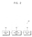
- FIG. 2 is a block diagram illustrating an image processing apparatus 100 according to an embodiment of the present invention.
- the image processing apparatus 100 may be embodied by a copier, a multifunction copier or the like.
- the image processing apparatus 100 may include a scanning part 110, an image processing part 120, and a printing part 130.
- the scanning part 110 scans a copy object to generate its image having a plurality of pixels.
- a book will be considered as the copy object.
- the book contacts a scan plane (not shown) by unfolding two pages to be copied. In this case, a center portion between the two pages is lifted up above the scan plane, and other portions of the two pages may contact the scan plane.
- An example of an input image 10 generated by the scanning part 110 is illustrated in Figure 1.
- the input image 10 includes page images 12 (12a and 12b) and a folding line 11 darkened between the page images 12a and 12b.
- the image processing part 120 detects the folding line 11 out of the input image 10 generated by the scanning part 110 and processes the input image 10 to generate an output image free from the detected folding line 11.
- the folding line 11 is selected as an example of a "certain region" in the pages.
- the image processing part 120 removes the folding line 11 from the input image 10 to generate the output image including only the page images 12a and 12b.
- the image processing part 120 may divide the input image 10 on the basis of the folding line 11 and generate a first output image and a second output image corresponding to the page images 12a and 12b, respectively.
- the folding line 11 may be an example of a row of pixels having a sudden change in brightness as compared to adjacent pixels.
- the printing part 130 prints the output image generated by the image processing part 120 on a record medium such as a paper.
- the printing part 130 may print the output image on one sheet of paper or may print the first and second output images on separate papers.
- the printing part 130 may perform at least one of various printing operations, for example, inkjet printing, laser printing, etc.
- the image processing part 120 may be incorporated in a separate image processing apparatus (not shown) from the scanning part 110 and/or the printing part 130.
- the image processing part 120 determines candidate pixels whose variations of brightness in a first direction exceed a first reference value, among a plurality of pixels that constitute the input image 10. In other words, the image processing part 120 detects the candidate pixels corresponding to an edge whose brightness suddenly changes in a horizontal direction in the input image 10.
- the horizontal direction refers to a direction substantially perpendicular to the folding line 11 and a vertical direction refers to a direction substantially parallel to the folding line 11.
- the candidate pixels are determined by detecting the variations of brightness of pixels using conventional methods such as Sobel edge detection and so on.
- the image processing part 120 finds a horizontal and a vertical brightness gradient of pixels.
- the following Equation 1 and Equation 2 may be used to find the horizontal and vertical brightness gradients.
- Gx ( Image ( x - 1 , y - 1 ) - Image ( x - 1 , y ) + Image ( x - 1 , y + 1 ) - Image ⁇ x + 1 , y - 1 Image ( x + 1 , y ) + Image ⁇ x + 1 , y + 1 ) / 3
- Gy ( Image ( x - 1 , y - 1 ) - Image ( x , y - 1 ) + Image ( x + 1 , y - 1 ) - Image ⁇ x - 1 , y + 1 Image ( x , y + 1 ) + Image ⁇ x + 1 , y + 1 ) / 3
- Gx represents variations of brightness of pixels in an x-direction, i.e., a vertical direction
- Gy represents variations of brightness of pixels in a y-direction, i.e., a horizontal direction
- Image(x,y) represents brightness of any pixel(x,y).
- the image processing part 120 determines pixels whose variations of brightness in the horizontal direction exceed the first reference value, as the candidate pixels.
- the first reference value may be twice the variations of brightness of pixels in the vertical direction. For example, if Gy>Gx*2, that is, if the variations of brightness of pixels in the horizontal direction is more than twice the variations of brightness of pixels in the vertical direction, the image processing part 120 may determine the pixels as the candidate pixels.
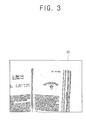
- Figure 3 illustrates an edge map 20 as a resultant image of the input image 10 of Figure 1 which may be obtained when only the candidate pixels of the input image are dotted.
- the edge map 20 may have noises depending on characteristics of the input image 10.
- the image processing part 120 may process the image in a unit of a pixel block, which is a set of adjacent pixels, not in a unit of a pixel, in order to minimize effects of the noises and increase a speed of calculation. This image processing is referred to as a sub-sampling.
- the unit of 9*9 pixel blocks is used.
- the image processing part 120 determines candidate pixel blocks, each including at least one candidate pixel, among the 9*9 pixel blocks. In this case, representative values of the candidate pixel blocks are set to be an on-state.
- Figure 4 illustrates a sub-sampled image 30 of the input image 10 of Figure 1 according to the sub-sampling image processing.
- the image processing may be performed in either the unit of "pixel” or the unit of "pixel block.”
- the unit of "pixel” will be described by way of an example, but the unit of "pixel block” can be used for the image processing.
- a peak value in the folding line may be reduced due to a skew which may exist in an actual image depending on environments where the input image is obtained or the copy object is scanned. This may lower the precision of detection of the folding line. Accordingly, the image processing part 120 dilates the sub-sampled image 30 in the horizontal direction, which is called morphological dilation.
- the image processing part 120 may substitute at least one pixel arranged parallel to a particular candidate pixel with a new candidate pixel. For example, as illustrated in Figure 5, when a candidate pixel 41 is detected, the image processing part 120 determines five pixels 42 arranged in the left of the detected candidate pixel 41 as new candidate pixels.
- Figure 6 illustrates an image 50 generated through the dilation process.
- the image processing part 120 detects a portion where the number of candidate pixels in the vertical direction increases suddenly, that is, a region where the number of candidate pixels in the vertical direction reaches a peak. In other words, the image processing part 120 determines a region where the total number of candidate pixels existing in a row of pixels in the vertical direction exceeds a second reference value, as the folding line 11.
- the portion determined as the folding line 11 is removed from the input image to generate the output image.
- two images disposed opposite to each other with respect to the portion determined as the folding line 11 may be separated from the input image 10 to generate two output images.
- the second reference value may correspond to 80% of the total number of pixels in the row of pixels in the vertical direction.
- the second reference value may be 80% of the total number of pixels in the row of pixels in the vertical direction within the page images 12.
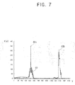
- Figure 7 is a graph 60 illustrating the total number f(y) of candidate pixels determined at a point i (i is a natural number) on a y-axis of an image.
- f(y) has its peaks 60a and 60b near the folding line and at an end portion of the book.
- the image processing part 120 may detect a region of the page images in the input image and then consider a positional relation of the detected region with the peaks.
- the image processing part 120 may discriminate the peak 60a corresponding to the folding line 11 in consideration of characteristics of an image before and after a peak.
- Figure 8 is a flow chart illustrating an image processing method according to an embodiment of the present invention. Referring to Figure 8, with respect to a plurality of pixels constituting an input image, variations of brightness of pixels in a horizontal direction are compared with variations of brightness of pixels in a vertical direction, and then, based on the comparison, candidate pixels whose brightness changes suddenly are determined at operation S110.
- operation S120 sub-sampling is performed on an image in which only the candidate pixels determined at the operation S110 are dotted in order to minimize effects of noises and reduce the amount of computation.
- operation S130 morphological dilation is performed on the image sub-sampled at the operation S120 in order to minimize an effect of a skew or the like.
- a folding line in which the number of candidate pixels increases suddenly in the vertical direction is determined at operation S140.
- an output image free from the folding line determined at the operation S140 is generated at operation S150.
- a row in which the number of candidate pixels increases suddenly in the vertical direction may be determined, and then, an input image may be divided based on the determined row of pixels to generate an output image at operation S150.
- the image processing method may further include an operation S910 of scanning a copy object to generate an input image before the operation S100 of Figure 8, and an operation S920 of printing the generated output image on a record medium such as a paper after the operation S100 of Figure 8, as illustrated in Figure 9.
- the present invention can also be embodied as computer-readable codes as a program on a computer-readable recording medium to perform the above-described method.
- the computer-readable recording medium is any data storage device that can store data which can be thereafter read by a computer system. Examples of the computer-readable recording media include read-only memory (ROM), random-access memory (RAM), CD-ROMs, magnetic tapes, floppy disks, optical data storage devices, and carrier waves (such as data transmission through the Internet).
- the computer-readable recording medium can also be distributed over network-coupled computer systems so that the computer-readable code is stored and executed in a distributed fashion. Also, functional programs, codes, and code segments to accomplish the present invention can be easily construed by programmers skilled in the art to which the present invention pertains.
- the present invention provides an image processing apparatus and an image processing method, which are capable of removing a certain region of an input image with little amount of computation and high applicability.
- the certain region may be circumferences of right and left pages of a book, which come out relatively darker, compared to other regions of the pages.
- candidate pixels may be determined in consideration of sudden change of brightness of pixels in both of the horizontal and vertical directions.
Landscapes
- Engineering & Computer Science (AREA)
- Multimedia (AREA)
- Signal Processing (AREA)
- Computer Vision & Pattern Recognition (AREA)
- Physics & Mathematics (AREA)
- General Physics & Mathematics (AREA)
- Theoretical Computer Science (AREA)
- Image Processing (AREA)
- Editing Of Facsimile Originals (AREA)
Abstract
Description
- The present invention relates to an image processing apparatus and an image processing method, and more particularly, to an image processing apparatus and an image processing method, which are capable of removing a certain region of an input image or dividing a certain portion of the input image with a reduced computation and a high applicability.
- An image processing apparatus, such as a copier, a multifunction copier or the like, incorporates scanning an object to generate its image as a copy of the object, processing the generated image, and printing the processed image on a record medium such as a paper. Such image processing may be performed by a separate image processing apparatus.
- There are various objects that we can copy, and among them are books copied in two pages at the same time by unfolding them. In this case, a center line formed between the two pages is lifted up from a scan plane during scanning, so relatively less light reaches a region along the center line. Thus, the region comes out relatively darker, compared to other copied area of the two pages. In particular, a very middle line (hereinafter referred to as "folding line") comes out the darkest. An example of a
folding line 11 is shown in Figure 1. - It is desirable to remove a folding line image portion corresponding to a portion where substantial image distortion occurs. As one of conventional techniques for removing the folding line image,
U.S. Patent No. 6,330,050 discloses a conventional technique which estimates heights of portions on coordinates of an input image from a scan plane, and corrects a distortion of the image based on the estimated heights. - However, this technique has a problem in that a great deal of computation is required to estimate the heights and this technique is applicable only when the folding line is parallel to a scanner, that is, is perpendicular to a main scan direction.
- The present invention provides an image processing apparatus and an image processing method, which are capable of removing a certain region of an input image or dividing a certain portion of the input image with a reduced computation and a high applicability.
- Additional aspects and advantages of the present invention will be set forth in part in the description which follows and, in part, will be obvious from the description, or may be learned by practice of the invention.
- The foregoing and/or other aspects of the present invention may be achieved by providing an image processing method including determining one or more candidate pixels having variation of brightness in a first direction, among a plurality of pixels constituting an input image, the variation of brightness exceeding a first reference value, determining a certain region in which a total number of candidate pixels existing in a row of pixels in a second direction different from the first direction exceeds a second reference value, and generating an output image free from the determined certain region.
- The first and second directions may be horizontal and vertical directions of the input image, respectively.
- The first reference value may be twice the variation of brightness in the vertical direction.
- The second reference value may be equal to 80% of the total number of corresponding pixels in the row of pixels.
- The determining of the one or more candidate pixels may further include determining a candidate pixel block comprising at least one candidate pixel among a plurality of 9*9 pixel blocks constituting the input image, and the determining of the certain region comprises determining the certain region in a unit of the candidate pixel block.
- The image processing method may further include substituting the candidate pixel block for at least one pixel block arranged in the horizontal direction from the candidate pixel block.
- The image processing method may further include generating the input image by scanning a copy object.
- The image processing method may further include printing the generated output image on a record medium.
- The generating of the output image comprises dividing the input image into two output images on the basis of the determined certain region.
- The foregoing and/or other aspects of the present invention may also be achieved by providing an image processing apparatus including an image processing part that determines one or more candidate pixels having variation of brightness in a first direction, among a plurality of pixels constituting an input image, the variation of brightness exceeding a first reference value, and a certain region in which a total number of candidate pixels existing in a row of pixels in a second direction different from the first direction exceeds a second reference value, and generates an output image free from the determined certain region.
- The first and second directions may be horizontal and vertical directions of the input image, respectively.
- The first reference value may be twice the variation of brightness in the vertical direction.
- The second reference value may be equal to 80% of the total number of corresponding pixels in the row of pixels.
- The image processing part may determine a candidate pixel block comprising at least one candidate pixel among a plurality of 9*9 pixel blocks constituting the input image, and determines the certain region in a unit of candidate pixel block.
- The image processing part may substitute the candidate pixel block for at least one pixel block arranged in the horizontal direction from the candidate pixel block.
- The image processing apparatus may further include a scanning part that generates the input image by scanning a copy object.
- The image processing apparatus may further include a printing part that prints the generated output image on a record medium.
- The image processing part may generate the output image by dividing the input image into two output images on the basis of the determined certain region.
- The foregoing and/or other aspects of the present invention may also be achieved by providing a computer readable recording medium to perform a method, the method including determining one or more candidate pixels having variation of brightness in a first direction, among a plurality of pixels constituting an input image, the variation of brightness exceeding a first reference value; determining a certain region in which a total number of candidate pixels existing in a row of pixels in a second direction different from the first direction exceeds a second reference value; and generating an output image free from the determined certain region.
- The foregoing and/or other aspects of the present invention may also be achieved by providing an image processing apparatus including an image processing part to determine a region of an image as a folding line when the region includes one or more pixels having a predetermined brightness change and when the number of the one or more pixels is greater than a reference number, and to remove the region from the image to generate an output image.
- The image processing part may adjust brightness of the one or more pixels to determine the region of the image as the folding line.
- The image processing part may determine the region of the image as the folding line according to a unit of a block including one or more pixels.
- The image processing part may dilate the one or more pixels to determine the region of the image as the folding line.
- The output image may include two images disposed opposite to each other with respect to the region.
- These and/or other aspects and advantages of the present invention will become apparent and more readily appreciated from the following description of the embodiments, taken in conjunction with the accompanying drawings of which:
- Figure 1 is a view illustrating a scanned image having a folding line;
- Figure 2 is a block diagram illustrating an image processing apparatus according to an embodiment of the present invention;
- Figure 3 is a view illustrating an edge map obtained in the image processing apparatus of Figure 2 according to an embodiment of the present invention;
- Figure 4 is a view illustrating a sub-sampled image obtained in the image processing apparatus of Figure 2 according to an embodiment of the present invention;
- Figure 5 is a view illustrating a dilation process of the image processing apparatus of Figure 2 according to an embodiment of the present invention;
- Figure 6 is a view illustrating a generated image after the dilation process of Figure 5 according to an embodiment of the present invention;
- Figure 7 is a graph illustrating a total number of pixels at a point on a y-axis of an image according to an embodiment of the present invention;
- Figure 8 is a flow chart illustrating an image processing method according to an embodiment of the present invention; and
- Figure 9 is a flow chart illustrating an image processing method of an image processing apparatus according to an embodiment of the present invention.
- Reference will now be made in detail to the embodiments of the present invention, examples of which are illustrated in the accompanying drawings, wherein like reference numerals refer to the like elements throughout. The embodiments are described below in order to explain the present invention by referring to the figures.
- Figure 2 is a block diagram illustrating an
image processing apparatus 100 according to an embodiment of the present invention. Theimage processing apparatus 100 may be embodied by a copier, a multifunction copier or the like. - Referring to Figure 2, the
image processing apparatus 100 may include ascanning part 110, animage processing part 120, and aprinting part 130. - The
scanning part 110 scans a copy object to generate its image having a plurality of pixels. In the present embodiment, a book will be considered as the copy object. The book contacts a scan plane (not shown) by unfolding two pages to be copied. In this case, a center portion between the two pages is lifted up above the scan plane, and other portions of the two pages may contact the scan plane. An example of aninput image 10 generated by thescanning part 110 is illustrated in Figure 1. Theinput image 10 includes page images 12 (12a and 12b) and afolding line 11 darkened between thepage images - Referring to Figures 1 and 2, the
image processing part 120 detects thefolding line 11 out of theinput image 10 generated by thescanning part 110 and processes theinput image 10 to generate an output image free from the detectedfolding line 11. In the present embodiment, thefolding line 11 is selected as an example of a "certain region" in the pages. Theimage processing part 120 removes thefolding line 11 from theinput image 10 to generate the output image including only thepage images image processing part 120 may divide theinput image 10 on the basis of thefolding line 11 and generate a first output image and a second output image corresponding to thepage images folding line 11 may be an example of a row of pixels having a sudden change in brightness as compared to adjacent pixels. - The
printing part 130 prints the output image generated by theimage processing part 120 on a record medium such as a paper. Theprinting part 130 may print the output image on one sheet of paper or may print the first and second output images on separate papers. Theprinting part 130 may perform at least one of various printing operations, for example, inkjet printing, laser printing, etc. - The
image processing part 120 may be incorporated in a separate image processing apparatus (not shown) from thescanning part 110 and/or theprinting part 130. - The
image processing part 120 determines candidate pixels whose variations of brightness in a first direction exceed a first reference value, among a plurality of pixels that constitute theinput image 10. In other words, theimage processing part 120 detects the candidate pixels corresponding to an edge whose brightness suddenly changes in a horizontal direction in theinput image 10. In the present embodiment, the horizontal direction refers to a direction substantially perpendicular to thefolding line 11 and a vertical direction refers to a direction substantially parallel to thefolding line 11. - The candidate pixels are determined by detecting the variations of brightness of pixels using conventional methods such as Sobel edge detection and so on. The
image processing part 120 finds a horizontal and a vertical brightness gradient of pixels. The followingEquation 1 andEquation 2 may be used to find the horizontal and vertical brightness gradients.

- Gx represents variations of brightness of pixels in an x-direction, i.e., a vertical direction, Gy represents variations of brightness of pixels in a y-direction, i.e., a horizontal direction, and Image(x,y) represents brightness of any pixel(x,y).
- In addition, the
image processing part 120 determines pixels whose variations of brightness in the horizontal direction exceed the first reference value, as the candidate pixels. In the present embodiment, the first reference value may be twice the variations of brightness of pixels in the vertical direction. For example, if Gy>Gx*2, that is, if the variations of brightness of pixels in the horizontal direction is more than twice the variations of brightness of pixels in the vertical direction, theimage processing part 120 may determine the pixels as the candidate pixels. Figure 3 illustrates anedge map 20 as a resultant image of theinput image 10 of Figure 1 which may be obtained when only the candidate pixels of the input image are dotted. - The
edge map 20 may have noises depending on characteristics of theinput image 10. Theimage processing part 120 may process the image in a unit of a pixel block, which is a set of adjacent pixels, not in a unit of a pixel, in order to minimize effects of the noises and increase a speed of calculation. This image processing is referred to as a sub-sampling. In the present embodiment, the unit of 9*9 pixel blocks is used. Theimage processing part 120 determines candidate pixel blocks, each including at least one candidate pixel, among the 9*9 pixel blocks. In this case, representative values of the candidate pixel blocks are set to be an on-state. Figure 4 illustrates asub-sampled image 30 of theinput image 10 of Figure 1 according to the sub-sampling image processing. - In the present embodiment, the image processing may be performed in either the unit of "pixel" or the unit of "pixel block." In the following description, the unit of "pixel" will be described by way of an example, but the unit of "pixel block" can be used for the image processing.
- A peak value in the folding line may be reduced due to a skew which may exist in an actual image depending on environments where the input image is obtained or the copy object is scanned. This may lower the precision of detection of the folding line. Accordingly, the
image processing part 120 dilates thesub-sampled image 30 in the horizontal direction, which is called morphological dilation. - The
image processing part 120 may substitute at least one pixel arranged parallel to a particular candidate pixel with a new candidate pixel. For example, as illustrated in Figure 5, when acandidate pixel 41 is detected, theimage processing part 120 determines fivepixels 42 arranged in the left of the detectedcandidate pixel 41 as new candidate pixels. Figure 6 illustrates animage 50 generated through the dilation process. - In order to detect the
folding line 11, theimage processing part 120 detects a portion where the number of candidate pixels in the vertical direction increases suddenly, that is, a region where the number of candidate pixels in the vertical direction reaches a peak. In other words, theimage processing part 120 determines a region where the total number of candidate pixels existing in a row of pixels in the vertical direction exceeds a second reference value, as thefolding line 11. The portion determined as thefolding line 11 is removed from the input image to generate the output image. Alternatively, two images disposed opposite to each other with respect to the portion determined as thefolding line 11 may be separated from theinput image 10 to generate two output images. In the present embodiment, the second reference value may correspond to 80% of the total number of pixels in the row of pixels in the vertical direction. If thepage images 12 do not extend throughout in the vertical direction, like theinput image 10 illustrated in Figure 1, the second reference value may be 80% of the total number of pixels in the row of pixels in the vertical direction within thepage images 12. Figure 7 is agraph 60 illustrating the total number f(y) of candidate pixels determined at a point i (i is a natural number) on a y-axis of an image. - As illustrated in Figure 7, f(y) has its
peaks peak 60a, which corresponds to thefolding line 11, out of the twopeaks image processing part 120 may detect a region of the page images in the input image and then consider a positional relation of the detected region with the peaks. As an alternative embodiment, theimage processing part 120 may discriminate thepeak 60a corresponding to thefolding line 11 in consideration of characteristics of an image before and after a peak. - Figure 8 is a flow chart illustrating an image processing method according to an embodiment of the present invention. Referring to Figure 8, with respect to a plurality of pixels constituting an input image, variations of brightness of pixels in a horizontal direction are compared with variations of brightness of pixels in a vertical direction, and then, based on the comparison, candidate pixels whose brightness changes suddenly are determined at operation S110.
- Next, at operation S120, sub-sampling is performed on an image in which only the candidate pixels determined at the operation S110 are dotted in order to minimize effects of noises and reduce the amount of computation. Next, at operation S130, morphological dilation is performed on the image sub-sampled at the operation S120 in order to minimize an effect of a skew or the like.
- Next, with respect to the image obtained at the operation S130, a folding line in which the number of candidate pixels increases suddenly in the vertical direction is determined at operation S140. Next, an output image free from the folding line determined at the operation S140 is generated at operation S150.
- As an alternative embodiment, with respect to the image obtained at the operation S130, a row in which the number of candidate pixels increases suddenly in the vertical direction may be determined, and then, an input image may be divided based on the determined row of pixels to generate an output image at operation S150.
- As another alternative embodiment, the image processing method may further include an operation S910 of scanning a copy object to generate an input image before the operation S100 of Figure 8, and an operation S920 of printing the generated output image on a record medium such as a paper after the operation S100 of Figure 8, as illustrated in Figure 9.
- The present invention can also be embodied as computer-readable codes as a program on a computer-readable recording medium to perform the above-described method. The computer-readable recording medium is any data storage device that can store data which can be thereafter read by a computer system. Examples of the computer-readable recording media include read-only memory (ROM), random-access memory (RAM), CD-ROMs, magnetic tapes, floppy disks, optical data storage devices, and carrier waves (such as data transmission through the Internet). The computer-readable recording medium can also be distributed over network-coupled computer systems so that the computer-readable code is stored and executed in a distributed fashion. Also, functional programs, codes, and code segments to accomplish the present invention can be easily construed by programmers skilled in the art to which the present invention pertains.
- As described above, the present invention provides an image processing apparatus and an image processing method, which are capable of removing a certain region of an input image with little amount of computation and high applicability.
- In addition, according to the present invention, it is possible to divide and print page images in an input image through detection of a folding line of a book.
- In addition, according to the present invention, by performing sub-sampling, an image robust to noises can be generated and the amount of computation for process of the image can be further reduced.
- Furthermore, according to the present invention, by performing morphological dilation, a certain region of an image can be discriminated more precisely.
- For example, although the folding line has been illustrated as the certain region in the above embodiments, the certain region may be circumferences of right and left pages of a book, which come out relatively darker, compared to other regions of the pages. In this case, candidate pixels may be determined in consideration of sudden change of brightness of pixels in both of the horizontal and vertical directions.
- Although a few embodiments of the present invention have been shown and described, it will be appreciated by those skilled in the art that changes may be made in these embodiments without departing from the scope of the invention as defined in the appended claims.
Claims (24)
- An image processing method comprising:determining one or more candidate pixels among a plurality of pixels constituting an input image, the one or more candidate pixels having a variation of brightness compared to adjacent pixels in a first direction exceeding a first reference value;determining a certain region in which a total number of candidate pixels existing in a row of pixels in a second direction different from the first direction exceeds a second reference value; andgenerating an output image excluding the determined certain region.
- The image processing method according to claim 1, wherein the first and second directions are horizontal and vertical directions of the input image, respectively.
- The image processing method according to claim 1 or 2, wherein the first reference value is twice a variation of brightness in the second direction.
- The image processing method according to any one of the preceding claims, wherein the second reference value is equal to 80% of a total number of corresponding pixels in the row of pixels.
- The image processing method according to any one of the preceding claims, wherein the determining of the one or more candidate pixels comprises:determining a candidate pixel block comprising at least one candidate pixel among a plurality of N by N pixel blocks constituting the input image, N being a natural number; andthe determining of the certain region comprises determining the certain region in a unit of the candidate pixel block.
- The image processing method according to claim 5, further comprising:substituting the candidate pixel block for at least one pixel block arranged in the first direction from the candidate pixel block.
- The image processing method according to any one of the preceding claims, further comprising: generating the input image by scanning a copy object.
- The image processing method according to any one of the preceding claims, further comprising:printing the generated output image on a record medium.
- The image processing method according to any of the preceding claims, wherein the generating of the output image comprises dividing the input image into at least two output images on the basis of the determined certain region.
- An image processing apparatus comprising:an image processing part (120) configured to determine one or more candidate pixels among a plurality of pixels constituting an input image, the one or more candidate pixels having a variation of brightness compared to adjacent pixels in a first direction exceeding a first reference value, and to determine a certain region in which a total number of candidate pixels existing in a row of pixels in a second direction different from the first direction exceeds a second reference value, and to generate an output image excluding the determined certain region.
- The image processing apparatus according to claim 10, wherein the first and second directions are horizontal and vertical directions of the input image, respectively.
- The image processing apparatus according to claim 10 or 11, wherein the first reference value is twice the variation of brightness in the second direction.
- The image processing apparatus according to any one of claims 11 to 12, wherein the second reference value is equal to 80% of a total number of corresponding pixels in the row of pixels.
- The image processing apparatus according to any one of claims 10 to 13, wherein the image processing part (120) is configured to determine a candidate pixel block comprising at least one candidate pixel among a plurality of N by N pixel blocks constituting the input image, N being a natural number, and determines the certain region in a unit of the candidate pixel block.
- The image processing apparatus according to claim 14, wherein the image processing part (120) is configured to substitute the candidate pixel block for at least one pixel block arranged in the horizontal direction from the candidate pixel block.
- The image processing apparatus according to any one of claims 10 to 15, further comprising:a scanning part (110) configured to generate the input image by scanning a copy object.
- The image processing apparatus according to any one of claims 10 to 16, further comprising:a printing part (130) configured to print the generated output image on a record medium.
- The image processing apparatus according to any one of claims 10 to 17, wherein the image processing part (120) is configured to generate the output image by dividing the input image into at least two output images on the basis of the determined certain region.
- A computer readable recording medium containing computer readable codes as a program to perform an image processing method according to any one of claims 1 to 9.
- An image processing apparatus comprising:an image processing part (120) configured to determine a region of an image as a folding line when the region includes one or more pixels having a predetermined brightness change and when the number of the one or more pixels is greater than a reference number, and to remove the region from the image to generate an output image.
- The image processing apparatus according to claim 20, wherein the image processing part (120) is configured to adjust brightness of the one or more pixels to determine the region of the image as the folding line.
- The image processing apparatus according to claim 20, wherein the image processing part (120) is configured to determine the region of the image as the folding line according to a unit of a block including one or more pixels.
- The image processing apparatus according to claim 20, wherein the image processing part (120) is configured to dilate the one or more pixels to determine the region of the image as the folding line.
- The image processing apparatus according to claim 20, wherein the output image comprises two images disposed opposite to each other with respect to the region.
Applications Claiming Priority (1)
| Application Number | Priority Date | Filing Date | Title |
|---|---|---|---|
| KR1020060066532A KR100944002B1 (en) | 2006-07-14 | 2006-07-14 | Image processing unit and image processing method |
Publications (2)
| Publication Number | Publication Date |
|---|---|
| EP1879374A1 true EP1879374A1 (en) | 2008-01-16 |
| EP1879374B1 EP1879374B1 (en) | 2018-09-19 |
Family
ID=38472939
Family Applications (1)
| Application Number | Title | Priority Date | Filing Date |
|---|---|---|---|
| EP07109288.6A Not-in-force EP1879374B1 (en) | 2006-07-14 | 2007-05-31 | Image processing apparatus and method |
Country Status (4)
| Country | Link |
|---|---|
| US (2) | US7848590B2 (en) |
| EP (1) | EP1879374B1 (en) |
| KR (1) | KR100944002B1 (en) |
| CN (1) | CN101106630B (en) |
Families Citing this family (4)
| Publication number | Priority date | Publication date | Assignee | Title |
|---|---|---|---|---|
| KR100944002B1 (en) * | 2006-07-14 | 2010-02-24 | 삼성전자주식회사 | Image processing unit and image processing method |
| JP4433030B2 (en) * | 2007-10-01 | 2010-03-17 | ブラザー工業株式会社 | Image processing apparatus and control program for image processing apparatus |
| US8306335B2 (en) * | 2011-03-30 | 2012-11-06 | Seiko Epson Corporation | Method of analyzing digital document images |
| JP2025027225A (en) * | 2023-08-14 | 2025-02-27 | キヤノン株式会社 | IMAGE PROCESSING APPARATUS, CONTROL METHOD FOR IMAGE PROCESSING APPARATUS, AND PROGRAM |
Citations (6)
| Publication number | Priority date | Publication date | Assignee | Title |
|---|---|---|---|---|
| US6124950A (en) * | 1997-04-15 | 2000-09-26 | Minolta Co., Ltd. | Apparatus and method for detecting book document along the longitudinal edge |
| WO2001011864A2 (en) * | 1999-08-11 | 2001-02-15 | Asci, Inc. | System and method for processing optically scanned documents |
| EP1093084A1 (en) * | 1998-06-30 | 2001-04-18 | Sharp Kabushiki Kaisha | Image correction device |
| EP1294174A2 (en) * | 2001-08-21 | 2003-03-19 | Konica Corporation | Image erasure of areas outside a document |
| US20060007505A1 (en) * | 2004-06-30 | 2006-01-12 | Mahesan Chelvayohan | Bound document scanning method and apparatus |
| US20060193533A1 (en) * | 2001-08-27 | 2006-08-31 | Tadashi Araki | Method and system for correcting distortions in image data scanned from bound originals |
Family Cites Families (21)
| Publication number | Priority date | Publication date | Assignee | Title |
|---|---|---|---|---|
| US4538181A (en) * | 1983-02-28 | 1985-08-27 | Kollmorgen Technologies | Optical scanner |
| DE69216315T2 (en) * | 1991-07-26 | 1997-06-26 | Oce Nederland Bv | Method and system for determining a reference value for a color display variable obtained by scanning an original with a color scanner |
| DE69228647T2 (en) | 1991-11-01 | 1999-09-23 | Eastman Kodak Co., Rochester | Method and device for detecting text in dot matrix printing to improve optical character recognition |
| US5377019A (en) * | 1991-12-02 | 1994-12-27 | Minolta Co., Ltd. | Document reading apparatus having a function of determining effective document region based on a detected data |
| JP2956377B2 (en) * | 1992-08-24 | 1999-10-04 | ミノルタ株式会社 | Image reading device |
| JPH05336341A (en) * | 1992-05-29 | 1993-12-17 | Ricoh Co Ltd | Image processing device |
| US5677776A (en) * | 1994-09-29 | 1997-10-14 | Minolta Co., Ltd. | Image reader for processing an image of a document |
| JP3384208B2 (en) * | 1994-09-29 | 2003-03-10 | ミノルタ株式会社 | Image reading device |
| JP3199978B2 (en) * | 1995-03-31 | 2001-08-20 | シャープ株式会社 | Liquid crystal display |
| US6330050B1 (en) * | 1997-07-24 | 2001-12-11 | Ricoh Company, Ltd | Image processing device for providing correction of a curvature distortion of a bound portion of a spread book |
| US6549295B1 (en) * | 1997-12-15 | 2003-04-15 | Insight, Inc. | Method for making products having merged images |
| US6462835B1 (en) * | 1998-07-15 | 2002-10-08 | Kodak Polychrome Graphics, Llc | Imaging system and method |
| JP2000041141A (en) | 1998-07-21 | 2000-02-08 | Murata Mach Ltd | Image processing unit |
| JP3807583B2 (en) * | 1999-04-19 | 2006-08-09 | 本田技研工業株式会社 | Road area determination device |
| JP4157251B2 (en) | 2000-03-30 | 2008-10-01 | パナソニック コミュニケーションズ株式会社 | Image processing apparatus and image processing method |
| JP3615462B2 (en) * | 2000-05-12 | 2005-02-02 | 三洋電機株式会社 | Automatic exposure control camera |
| JP2004032551A (en) * | 2002-06-27 | 2004-01-29 | Seiko Epson Corp | Image processing method, image processing apparatus, and projector |
| US7864349B2 (en) * | 2003-07-30 | 2011-01-04 | International Business Machines Corporation | Immediate verification of printed copy |
| KR101156114B1 (en) * | 2005-07-16 | 2012-06-20 | 삼성전자주식회사 | Method and apparatus for compensating image data in a scanning device |
| KR100944002B1 (en) * | 2006-07-14 | 2010-02-24 | 삼성전자주식회사 | Image processing unit and image processing method |
| US8290293B2 (en) * | 2006-10-17 | 2012-10-16 | Samsung Electronics Co., Ltd. | Image compensation in regions of low image contrast |
-
2006
- 2006-07-14 KR KR1020060066532A patent/KR100944002B1/en not_active Expired - Fee Related
-
2007
- 2007-01-24 US US11/626,480 patent/US7848590B2/en active Active
- 2007-05-31 EP EP07109288.6A patent/EP1879374B1/en not_active Not-in-force
- 2007-06-13 CN CN2007101110102A patent/CN101106630B/en not_active Expired - Fee Related
-
2010
- 2010-11-26 US US12/954,722 patent/US8238659B2/en not_active Expired - Fee Related
Patent Citations (6)
| Publication number | Priority date | Publication date | Assignee | Title |
|---|---|---|---|---|
| US6124950A (en) * | 1997-04-15 | 2000-09-26 | Minolta Co., Ltd. | Apparatus and method for detecting book document along the longitudinal edge |
| EP1093084A1 (en) * | 1998-06-30 | 2001-04-18 | Sharp Kabushiki Kaisha | Image correction device |
| WO2001011864A2 (en) * | 1999-08-11 | 2001-02-15 | Asci, Inc. | System and method for processing optically scanned documents |
| EP1294174A2 (en) * | 2001-08-21 | 2003-03-19 | Konica Corporation | Image erasure of areas outside a document |
| US20060193533A1 (en) * | 2001-08-27 | 2006-08-31 | Tadashi Araki | Method and system for correcting distortions in image data scanned from bound originals |
| US20060007505A1 (en) * | 2004-06-30 | 2006-01-12 | Mahesan Chelvayohan | Bound document scanning method and apparatus |
Also Published As
| Publication number | Publication date |
|---|---|
| US7848590B2 (en) | 2010-12-07 |
| US20110069335A1 (en) | 2011-03-24 |
| CN101106630B (en) | 2012-01-04 |
| KR100944002B1 (en) | 2010-02-24 |
| EP1879374B1 (en) | 2018-09-19 |
| US20080013857A1 (en) | 2008-01-17 |
| KR20080007025A (en) | 2008-01-17 |
| CN101106630A (en) | 2008-01-16 |
| US8238659B2 (en) | 2012-08-07 |
Similar Documents
| Publication | Publication Date | Title |
|---|---|---|
| US8064721B2 (en) | Method and apparatus for removing noise from a digital image | |
| US20030063802A1 (en) | Image processing method, apparatus and system | |
| US8368964B2 (en) | Method for estimation of image defocus and defocus restoration | |
| EP1215881B1 (en) | Method and apparatus for Image distortion correction | |
| EP1221811A2 (en) | Estimation of local defocus distance and geometric distortion based on scanned image features | |
| EP1879374B1 (en) | Image processing apparatus and method | |
| EP2026135B1 (en) | Image forming apparatus and method thereof | |
| US6944353B2 (en) | Image processing system | |
| EP1310940A1 (en) | Color display device and method | |
| US20090161952A1 (en) | Image processing apparatus and image processing method | |
| US11328425B2 (en) | Image processing apparatus and non-transitory computer readable medium | |
| EP1310904A9 (en) | Method for processing document, recorded medium on which document processing program is recorded and document processor | |
| JP4084537B2 (en) | Image processing apparatus, image processing method, recording medium, and image forming apparatus | |
| US7545535B2 (en) | Robust automatic page size detection algorithm for scan application | |
| JP4005243B2 (en) | Image processing device | |
| JP2001285631A (en) | Area determining method and device | |
| JP4403993B2 (en) | Image processing apparatus, image forming apparatus, image processing method, and program | |
| JP2004145634A (en) | Image processing apparatus and image processing method | |
| JP7283145B2 (en) | Information processing device and information processing program | |
| JP2007128342A (en) | Image determination apparatus, image determination method, and image determination program | |
| JP2024089294A (en) | Print defect detection system and print defect detection program | |
| JP3957523B2 (en) | Color image processing apparatus, color image processing method, program, and recording medium | |
| JP4091174B2 (en) | Image processing apparatus and image processing method | |
| JP2024071828A (en) | Image processing device, method, and program | |
| JP2005208981A (en) | Featured value extraction device, method for extracting featured value, and document filing device |
Legal Events
| Date | Code | Title | Description |
|---|---|---|---|
| PUAI | Public reference made under article 153(3) epc to a published international application that has entered the european phase |
Free format text: ORIGINAL CODE: 0009012 |
|
| 17P | Request for examination filed |
Effective date: 20070531 |
|
| AK | Designated contracting states |
Kind code of ref document: A1 Designated state(s): AT BE BG CH CY CZ DE DK EE ES FI FR GB GR HU IE IS IT LI LT LU LV MC MT NL PL PT RO SE SI SK TR |
|
| AX | Request for extension of the european patent |
Extension state: AL BA HR MK YU |
|
| 17Q | First examination report despatched |
Effective date: 20080724 |
|
| AKX | Designation fees paid |
Designated state(s): DE FR GB NL |
|
| RAP1 | Party data changed (applicant data changed or rights of an application transferred) |
Owner name: SAMSUNG ELECTRONICS CO., LTD. |
|
| RAP1 | Party data changed (applicant data changed or rights of an application transferred) |
Owner name: S-PRINTING SOLUTION CO., LTD. |
|
| GRAP | Despatch of communication of intention to grant a patent |
Free format text: ORIGINAL CODE: EPIDOSNIGR1 |
|
| STAA | Information on the status of an ep patent application or granted ep patent |
Free format text: STATUS: GRANT OF PATENT IS INTENDED |
|
| RAP1 | Party data changed (applicant data changed or rights of an application transferred) |
Owner name: HP PRINTING KOREA CO., LTD. |
|
| INTG | Intention to grant announced |
Effective date: 20180615 |
|
| GRAS | Grant fee paid |
Free format text: ORIGINAL CODE: EPIDOSNIGR3 |
|
| GRAA | (expected) grant |
Free format text: ORIGINAL CODE: 0009210 |
|
| STAA | Information on the status of an ep patent application or granted ep patent |
Free format text: STATUS: THE PATENT HAS BEEN GRANTED |
|
| AK | Designated contracting states |
Kind code of ref document: B1 Designated state(s): DE FR GB NL |
|
| REG | Reference to a national code |
Ref country code: GB Ref legal event code: FG4D |
|
| REG | Reference to a national code |
Ref country code: DE Ref legal event code: R096 Ref document number: 602007056166 Country of ref document: DE |
|
| REG | Reference to a national code |
Ref country code: NL Ref legal event code: MP Effective date: 20180919 |
|
| PG25 | Lapsed in a contracting state [announced via postgrant information from national office to epo] |
Ref country code: NL Free format text: LAPSE BECAUSE OF FAILURE TO SUBMIT A TRANSLATION OF THE DESCRIPTION OR TO PAY THE FEE WITHIN THE PRESCRIBED TIME-LIMIT Effective date: 20180919 |
|
| REG | Reference to a national code |
Ref country code: DE Ref legal event code: R097 Ref document number: 602007056166 Country of ref document: DE |
|
| PLBE | No opposition filed within time limit |
Free format text: ORIGINAL CODE: 0009261 |
|
| STAA | Information on the status of an ep patent application or granted ep patent |
Free format text: STATUS: NO OPPOSITION FILED WITHIN TIME LIMIT |
|
| 26N | No opposition filed |
Effective date: 20190620 |
|
| REG | Reference to a national code |
Ref country code: DE Ref legal event code: R082 Ref document number: 602007056166 Country of ref document: DE Representative=s name: SCHOPPE, ZIMMERMANN, STOECKELER, ZINKLER, SCHE, DE Ref country code: DE Ref legal event code: R081 Ref document number: 602007056166 Country of ref document: DE Owner name: HEWLETT-PACKARD DEVELOPMENT COMPANY, L.P., SPR, US Free format text: FORMER OWNER: HP PRINTING KOREA CO., LTD., SUWON-SI, GYEONGGI-DO, KR |
|
| REG | Reference to a national code |
Ref country code: GB Ref legal event code: 732E Free format text: REGISTERED BETWEEN 20191212 AND 20191218 |
|
| PGFP | Annual fee paid to national office [announced via postgrant information from national office to epo] |
Ref country code: FR Payment date: 20210608 Year of fee payment: 16 |
|
| PGFP | Annual fee paid to national office [announced via postgrant information from national office to epo] |
Ref country code: GB Payment date: 20220426 Year of fee payment: 16 Ref country code: DE Payment date: 20210716 Year of fee payment: 16 |
|
| REG | Reference to a national code |
Ref country code: DE Ref legal event code: R119 Ref document number: 602007056166 Country of ref document: DE |
|
| GBPC | Gb: european patent ceased through non-payment of renewal fee |
Effective date: 20230531 |
|
| PG25 | Lapsed in a contracting state [announced via postgrant information from national office to epo] |
Ref country code: DE Free format text: LAPSE BECAUSE OF NON-PAYMENT OF DUE FEES Effective date: 20231201 Ref country code: GB Free format text: LAPSE BECAUSE OF NON-PAYMENT OF DUE FEES Effective date: 20230531 |
|
| PG25 | Lapsed in a contracting state [announced via postgrant information from national office to epo] |
Ref country code: FR Free format text: LAPSE BECAUSE OF NON-PAYMENT OF DUE FEES Effective date: 20230531 |