EP1879067A1 - Diaphragm device - Google Patents
Diaphragm device Download PDFInfo
- Publication number
- EP1879067A1 EP1879067A1 EP07013394A EP07013394A EP1879067A1 EP 1879067 A1 EP1879067 A1 EP 1879067A1 EP 07013394 A EP07013394 A EP 07013394A EP 07013394 A EP07013394 A EP 07013394A EP 1879067 A1 EP1879067 A1 EP 1879067A1
- Authority
- EP
- European Patent Office
- Prior art keywords
- diaphragm
- lens barrel
- vane
- frame
- cover
- Prior art date
- Legal status (The legal status is an assumption and is not a legal conclusion. Google has not performed a legal analysis and makes no representation as to the accuracy of the status listed.)
- Withdrawn
Links
- 230000001105 regulatory effect Effects 0.000 claims description 3
- 230000003287 optical effect Effects 0.000 description 11
- 230000002093 peripheral effect Effects 0.000 description 8
- 230000004048 modification Effects 0.000 description 2
- 238000012986 modification Methods 0.000 description 2
- 239000000470 constituent Substances 0.000 description 1
- 238000003384 imaging method Methods 0.000 description 1
- 230000000149 penetrating effect Effects 0.000 description 1
Images




Classifications
-
- G—PHYSICS
- G03—PHOTOGRAPHY; CINEMATOGRAPHY; ANALOGOUS TECHNIQUES USING WAVES OTHER THAN OPTICAL WAVES; ELECTROGRAPHY; HOLOGRAPHY
- G03B—APPARATUS OR ARRANGEMENTS FOR TAKING PHOTOGRAPHS OR FOR PROJECTING OR VIEWING THEM; APPARATUS OR ARRANGEMENTS EMPLOYING ANALOGOUS TECHNIQUES USING WAVES OTHER THAN OPTICAL WAVES; ACCESSORIES THEREFOR
- G03B9/00—Exposure-making shutters; Diaphragms
- G03B9/02—Diaphragms
-
- G—PHYSICS
- G03—PHOTOGRAPHY; CINEMATOGRAPHY; ANALOGOUS TECHNIQUES USING WAVES OTHER THAN OPTICAL WAVES; ELECTROGRAPHY; HOLOGRAPHY
- G03B—APPARATUS OR ARRANGEMENTS FOR TAKING PHOTOGRAPHS OR FOR PROJECTING OR VIEWING THEM; APPARATUS OR ARRANGEMENTS EMPLOYING ANALOGOUS TECHNIQUES USING WAVES OTHER THAN OPTICAL WAVES; ACCESSORIES THEREFOR
- G03B9/00—Exposure-making shutters; Diaphragms
- G03B9/02—Diaphragms
- G03B9/06—Two or more co-operating pivoted blades, e.g. iris type
Definitions
- the present invention relates to a diaphragm device.
- monitor cameras are broadly used, for example, at financial-institution branches or locations and retail stores.
- the monitor camera is equipped with a lens unit (lens barrel) similarly to the usual camera.
- a diaphragm device is arranged to regulate the amount of incident light.
- the diaphragm device is structured with precision components, including diaphragm vanes, a lever for moving the vanes, a driver device for electrically operating the lever (see, for example, JP-A-2003-233102 ).
- the monitor camera in its nature is possibly to be broken by a person who is not desired to be taken an image of by the monitor camera. For this reason, there is a need to improve the resistance to an impact force as compared to the usual camera.
- the monitor camera is damaged at its diaphragm device, imaging is no longer available properly because of the impossibility to regulate the amount of light. In this case, the monitor camera is not allowed to exhibit its monitor function.
- An object of an illustrative, non-limiting embodiment of the present invention is to provide a diaphragm device improved in the resistance to vibration, impacts and so on.
- a diaphragm device comprising: a diaphragm mechanism having a diaphragm vane and a diaphragm frame receiving the diaphragm vane; a diaphragm-mechanism cover fixed to a lens barrel to which the diaphragm mechanism is attached, the diaphragm-mechanism cover clamping the diaphragm mechanism with a receiving surface of the lens barrel.
- the diaphragm mechanism and the diaphragm-mechanism cover are inserted in the lens barrel through a side surface of the lens barrel, and a part of the diaphragm mechanism and a part of the diaphragm-mechanism cover protruding outward relative to the side surface of the lens barrel.
- the diaphragm device further comprises a supporting member in a portion of the diaphragm mechanism protruding outward relative to the side surface of the lens barrel, the supporting member supporting the diaphragm mechanism in a direction of the diaphragm mechanism detachable from the lens barrel.
- the diaphragm mechanism and the diaphragm-mechanism cover are to be inserted in the lens barrel, in a state that at least a part thereof protrudes relative to the side surface of the lens barrel.
- the diaphragm-mechanism cover is fixed to the lens barrel on which the diaphragm mechanism is attached, to clamp the diaphragm mechanism with the surface of the receiving surface of the lens barrel.
- the diaphragm-mechanism cover is provided with a supporting member in a portion of the diaphragm mechanism protruding outward relative to the side surface of the lens barrel and for supporting the diaphragm mechanism in a direction of the diaphragm mechanism detachable from the lens barrel.
- the diaphragm mechanism In the event that a force is applied by vibration, an impact or the like in the direction of the diaphragm mechanism detachable from the lens barrel, the diaphragm mechanism is clamped between the diaphragm-mechanism cover and the receiving surface of the lens barrel. Because the diaphragm mechanism is supported by the supporting member of the diaphragm-mechanism cover in the direction of the diaphragm mechanism detachable from the lens barrel, the diaphragm mechanism is positively prevented from falling off the lens barrel.
- the support member may be in abutment against an end surface of the diaphragm mechanism, in the direction of the diaphragm mechanism detachable from the lens barrel.
- the diaphragm mechanism can be positively suppressed from falling off the lens barrel.
- the support member may be provided in a manner surrounding an outer periphery of the diaphragm mechanism, in the portion of the diaphragm mechanism protruding outward relative to the side surface of the lens barrel. According to the structure, because the support member is provided in a manner surrounding an outer periphery of the diaphragm mechanism, the diaphragm mechanism can be supported positively. Even in the event that vibration, an impact or the like is applied, the diaphragm mechanism can be suppressed from falling off the lens barrel.
- the diaphragm vane may be opposed to one surface of the diaphragm-mechanism cover, a falling-off preventing rail being, provided protruding from the one surface of the diaphragm cover toward the diaphragm vane and for regulating the vane from moving vertically to a surface thereof.
- a falling-off preventing rail being, provided protruding from the one surface of the diaphragm cover toward the diaphragm vane and for regulating the vane from moving vertically to a surface thereof.
- the diaphragm mechanism may be attached to the diaphragm frame and has drive means for driving the diaphragm vane, the drive means having an engage unit that engages with the diaphragm frame when attached to the diaphragm frame, the diaphragm frame having an opening in which the engage unit is inserted, the engage unit being to deform in a course of being inserted in the opening and engage with an edge of the opening due to a restoration from deformation, the diaphragm-mechanism cover having a rib protruding toward the opening, the rib being provided in a direction the engage unit of deforming and in a position close to the engage unit when the diaphragm mechanism and the diaphragm-mechanism cover are attached to the lens barrel.
- the diaphragm-mechanism cover has a rib in the direction of the engage unit deforming and in a position close to the engage unit, the engage unit is suppressed from deforming by the abutment between the engage unit and the rib. Accordingly, the engage unit is positively prevented from deforming and going into disengagement from the opening edge. Even in the event that vibration, an impact or the like is applied, the drive means is positively suppressed from being detached from the diaphragm mechanism.
- a novel, improved diaphragm device can be provided which is improved in the resistance to vibration, an impact or the like.
- Fig. 1 is a sectional view showing a lens unit (barrel) having a diaphragm mechanism according to an exemplary embodiment of the invention, illustrating a vertical section taken along the optical axis P thereof.
- the lens unit 10 has a fixed cylinder 12.
- the fixed cylinder 12 is provided with a diaphragm mechanism 30.
- a lens frame 14 is arranged in front of the diaphragm mechanism 30 (closer to the subject) while a lens frame 16 is arranged in back of the diaphragm mechanism 30.
- a focus ring 18 and a zoom ring 20 are arranged outer of the fixed cylinder 12.
- the lens frame 14 holds a focus lens (group) 22 therein.
- the lens frame 14 is arranged with an engagement pin 14a projecting relative to the peripheral surface thereof.
- the fixed cylinder 12 is axially formed with a straight groove 12a.
- the lens frame 16 holds therein a zoom lens (group) 26.
- the lens frame 16 is arranged with an engagement pin 16a projecting relative to the peripheral surface thereof.
- the fixed cylinder 12 is axially formed with a straight groove 12b.
- the focus ring 18 is rotatably arranged over the outer peripheral surface of the fixed cylinder 12, in a position the lens frame 14 is arranged.
- the focus ring 18 has an inner peripheral surface in which a cam groove 18a is formed helically about the optical axis.
- the engagement pin 14a, attached on the lens frame 14, is in engagement with the cam groove 18a of the focus ring 18. Accordingly, rotating the focus ring 18 causes the intersection, between the cam groove 18a of the focus ring 18 and the straight groove 12a of the fixed cylinder 12, to displace axially. This causes the engagement pin 14a, lens frame 14 and focus lens 22 to axially displace in accordance with the intersection. In this manner, by rotating the focus ring 18, the focus lens 22 can be adjusted in position thus effecting focal adjustment.
- the zoom ring 20 is rotatably arranged over the outer peripheral surface of the fixed cylinder 12, in a position the lens frame 16 is arranged.
- the zoom ring 20 has an inner peripheral surface in which a cam groove 20a is formed helically about the optical axis.
- the engagement pin 16a, attached on the lens frame 16 is in engagement with the cam groove 20a of the zoom ring 20. Accordingly, rotating the zoom ring 20 causes the intersection, between the cam groove 20a of the zoom ring 20 and the straight groove 12b of the fixed cylinder 12, to displace in the optical axial direction. This causes the engagement pin 16a, lens frame 16 and zoom lens 26 to axially displace in accordance with the intersection.
- zoom lens 26 can be adjusted in position to adjust the focal length (zoom angle-of-view) thereof.
- zoom function may be provided to the front-group lens while focus function be to the rear-group lens.
- the diaphragm mechanism 30 has a diaphragm frame 32, two vanes 34, 36, a driver device (drive means) 38 for driving the vanes, and a lever 40 (not shown in Fig. 1) fixed on the dive shaft 38a of the driver device 38. Meanwhile, a diaphragm-mechanism cover 50 is arranged in front of the diaphragm mechanism 39, as shown in Fig. 1.
- the diaphragm mechanism 30 and the diaphragm-mechanism cover 50 constitute a diaphragm device of the embodiment.
- Fig. 2 shows a planar structure of the diaphragm mechanism 30, illustrating a state as viewed from a side closer to the subject.
- the diaphragm mechanism 30 has the diaphragm frame 32.
- the diaphragm frame 32 is provided with an aperture 32f circular in form about the optical axis P and a rib 32e.
- the rib 32e is provided in a manner protruding toward the subject, in a peripheral edge of the diaphragm frame 32, as shown in Figs. 1 and 2.
- the vanes 34, 36 are arranged laid one over another at the inner side of the rib 32e, as shown in Fig. 2.
- the vane 34 located closer to the subject, is formed with elongate openings 34a, 34b, 34c.
- the diaphragm frame 32 has engagement pins 32a, 32b, 32c, 32d that project toward the subject.
- the openings 34a, 34b, 34c are respectively in engagement with the three engagement pins 32a, 32b, 32c.
- the vane 36 is formed with openings 36a, 36b, 36c.
- the openings 36a, 36b, 36c are respectively in engagement with the three engagement pins 32a, 32b, 32d provided on the diaphragm frame 32.
- the engagement pins 32a, 32b, 32c, 32d are each made increased in diameter at the tip thereof in order to ensure the engagement with the vanes 34, 36.
- the vane 34 is formed with a cutout 34e corresponding to the aperture 32f of the diaphragm frame 34.
- the vane 36 is formed with a cutout 36e corresponding to the aperture 32f of the diaphragm frame 32.
- the driver device 38 is attached to a lower part of the diaphragm frame 32.
- the driver device 38 is attached from rear onto the diaphragm frame 32.
- the drive shaft 38a of the driver device 38 is directed to the diaphragm frame 32, and the drive shaft 38a is attached with the lever 40.
- the lever 40 has engagement pins 40a, 40b at its both ends. The engagement pin 40a is engaged with the opening 34d formed in the vane 34 while the engagement pin 40b is with the opening 36d formed in the vane 36.
- the lever 40 is shown in a state moved the greatest in the direction of the arrow A by means of the driver device 38.
- the vane 34 is in the lowermost position in Fig. 2 while the vane 36 is in the uppermost position. Accordingly, the cutout 34e of the vane 34 and the cutout 36e of the vane 36 are distant from each other to open the aperture 32f of the diaphragm frame 32, as shown in Fig. 2.
- an oprining 12c is formed penetrating to the interior, in the fixed cylinder at a lower part of the outer periphery thereof.
- the diaphragm mechanism 30 is inserted together with the diaphragm-mechanism cover 50, in the interior of the fixed cylinder 12 through the openings 12c.
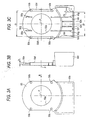
- Figs. 3A to 3C show a structure of the diaphragm-mechanism cover 50.
- Fig. 3A shows the diaphragm-mechanism cover 50 as viewed from the subject side
- Fig. 3B shows the diaphragm-mechanism cover 50 as viewed in a direction of the arrow B in Fig. 3A.
- Fig. 3C shows the diaphragm-mechanism cover 50 as viewed from the side of the diaphragm mechanism 30.
- the diaphragm-mechanism cover 50 has functions to prevent the diaphragm mechanism 30 from falling off the fixed cylinder 12, to prevent the vanes 34, 36 from falling off the diaphragm frame 32, and to prevent the driver device 38 from falling off the diaphragm frame 32.
- the diaphragm-mechanism cover 50 is formed through with an opening 50a about the optical axis P.
- screw holes 50b are formed at four locations to insert fixing screws 52.
- a diaphragm-mechanism support frame (supporting member) 50c is provided extending rearward.
- the diaphragm mechanism 30 has a region, where the driver device 38 is attached, protruding outward of the fixed cylinder 12, as shown in Fig. 1.
- the diaphragm-mechanism support frame 50c is provided in a manner surrounding, at the below and both sides, the diaphragm mechanism 30 in its portion protruding lower than the fixed cylinder 12.
- diaphragm-mechanism cover 50 has an abutment surface 50d to abut against a receiving surface 12d of the fixed cylinder 12, on the side closer to the diaphragm mechanism 30.
- the diaphragm-mechanism cover 50 has a height "h", with respect to the direction of the optical axis P, of from its main surface 50e closer to the diaphragm mechanism to the abutment surfaces 50d.
- the height "h" corresponds to a thickness "t" of the diaphragm frame 32 at its rib 32e portion shown in Fig. 1.
- the abutment surfaces 50d are structured such that the spacing d1 between the left and right ones shown in Fig. 3C is greater than a width d2 of the diaphragm frame 32 shown in Fig. 2.
- the spacing d1 between the abutment surfaces 50d may be structured equal to the width d2 of the diaphragm frame 32 so as to fit the diaphragm frame 32 between the abutment surfaces 50d.
- Fig. 4 shows the diaphragm mechanism 30 in a state covered with a diaphragm-mechanism cover 50, as viewed from the subject side.
- Fig. 5 shows a combination of the Fig. 4 diaphragm mechanism 30 and diaphragm-mechanism cover 50, in a state attached on the fixed cylinder 12.
- the diaphragm mechanism 30 and the diaphragm-mechanism cover 50 are inserted into the interior of the fixed cylinder 12 through the opening 12c of the fixed cylinder 12.
- the diaphragm mechanism 30 at its surface closer to the lens frame 16 abuts against the receiving surface 12d of the fixed cylinder 12, as shown in Fig. 1.
- the diaphragm-mechanism cover 50 at its abutment surface 50d abuts against the receiving surface 12d of the fixed cylinder 12 while the rib 32e at its tip abuts against a main surface 50e of the diaphragm-mechanism cover 50.
- the diaphragm frame 32 has a thickness t corresponding to the height "h" of the diaphragm-mechanism cover 50 wherein the width d2 of the diaphragm mechanism 30 is smaller than the spacing d1 between the abutment surfaces 50d. Accordingly, the diaphragm mechanism 30, in its widthwise direction, is received in between the two abutment surfaces 50d and, in its optical axis P direction, is clamped between the main surface 50e of the diaphragm-mechanism cover 50 and the receiving surface 12d of the fixed cylinder 12.
- the diaphragm mechanism 30 is fixedly clamped between the main surface 50e of the diaphragm-mechanism cover 50 and the receiving surface 12d of the fixed cylinder 12.
- the receiving surface 12d is shown at its inner peripheral end surface by the broken line 12e. The end face 12e is in a position radially closer to the optical axis P than the position the fixing screws 52 are screwed.
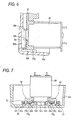
- Fig. 6 is a view showing the Fig. 1 driver device and its neighborhood by magnification, illustrating a state the lower end 32g of the diaphragm frame 32 is supported by the diaphragm-mechanism support frame 50c.
- a rib 50f is provided in an inner surface of the diaphragm-mechanism support frame 50c and in a direction toward the lower end 32g of the diaphragm frame 32.
- the diaphragm mechanism 30 and the diaphragm-mechanism cover 50 are inserted in the fixed cylinder 12 and the fixed screws 52 are tightened, the diaphragm-mechanism cover 50 is fixed to the fixed cylinder 12.
- the rib 50f of the diaphragm-mechanism support frame 50c abuts against the lower end 32g of the diaphragm frame 32 so that the diaphragm mechanism 30 at its lower end (lower end 32g of the diaphragm frame 32) can be supported by the rib 50f.
- the diaphragm mechanism 30 has a region, extending from the lower end 32g to the both sides, surrounded by the diaphragm-mechanism support frame 50c and supported by placing the spacing d3 between the abutment surfaces 50i of the inner surface of the diaphragm-mechanism support frame 50c (see Fig.
- a rib may be provided in the inner surface of the diaphragm-mechanism support frame 50c, to abut against the widthwise both sides of the diaphragm frame 32.
- the diaphragm mechanism 30 is positively supported by the diaphragm-mechanism support frame 50c.
- the diaphragm mechanism 30 is suppressed from moving toward departing from the fixed cylinder 12 by means of the diaphragm-mechanism support frame 50c and the rib 50f. This can firmly hold the diaphragm mechanism 30 on the fixed cylinder 12. Even in the event that a great impact force is applied to the lens unit 10, the diaphragm mechanism 30 can be positively prevented from falling off the fixed cylinder 12.
- vane falling-off preventing rails 50g are provided projecting toward the diaphragm mechanism 30.
- the vane falling-off preventing rails 50g are provided extending along the direction in which the vanes 34, 36 are driven.
- the vane-falling-off preventing rails 50g are defined in the height relative to the main surface 50e such that a predetermined clearance is provided between an upper surface of the vane-falling-off preventing rails 50g and the vane 34 located closer to the subject.
- Fig. 7 is a view showing a section taken along the one-dot chain line.I-I' in Fig. 4, in the state that the diaphragm mechanism 30 and the diaphragm-mechanism cover 50 are fixed to the fixed cylinder 12.
- Fig. 7 shows mainly a joint region of between the driver device 38 and the diaphragm frame 32.
- the driver device 38 is protruded with two engagers 38b extending toward the diaphragm frame 32. Meanwhile, the diaphragm frame 32 is provided with an opening 32h in which the engagers 38b are to be inserted.
- the engagers 38b of the driver device 38 are inserted in the opening 32h in the state the diaphragm-mechanism cover 50 is removed from the diaphragm mechanism 30.
- the engagers 38b deform toward the center of the opening 32h when being inserted in the opening 32h.
- the engagers 38b at their engagement faces 38c come into engagement with the opening 32h at its edge. This joins the driver device 38 and the diaphragm frame 32 together.
- the diaphragm-mechanism cover 50 has two ribs 50h for preventing the driver device 38 from falling off, as shown in Fig. 7.
- the driver device 38 is attached on the diaphragm frame 32 and then the diaphragm mechanism 30 and the diaphragm-mechanism cover 50 are mounted to the fixed cylinder 12, the falling-off preventing ribs 50h are inserted to between the two engagers 38b and abutted against the opposite surfaces of the two engagers 38b.
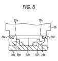
- Fig. 8 is a view for explaining the function of the falling-off preventing rib 50h.
- the engagers 38b deform in the direction to release the engagement of the engaging surface 38c and the opening 32h (in a direction of the arrow C in Fig. 8).
- the engagers 38b do not deform in the direction toward the arrow C. Accordingly, there occurs no disengagement at between the engagement surface 38c and the opening 32h edge. Even in the event that a great impact force is applied to the lens unit 10, the driver device 38 can be positively suppressed from falling off the diaphragm mechanism 30.
- the present embodiment can positively suppress the falling of the diaphragm mechanism 30 off the fixed cylinder 12, of the vanes 34, 36 off the diaphragm frame 32 and of the driver device 38 off the diaphragm frame 32. Therefore, it is possible to positively suppress the occurrence of a poor video image resulting from such falling off.
Landscapes
- Physics & Mathematics (AREA)
- General Physics & Mathematics (AREA)
- Lens Barrels (AREA)
- Diaphragms For Cameras (AREA)
Abstract
Description
- The present invention relates to a diaphragm device.
- Recently, monitor cameras (monitor CCTV cameras) are broadly used, for example, at financial-institution branches or locations and retail stores. The monitor camera is equipped with a lens unit (lens barrel) similarly to the usual camera. In the lens unit, a diaphragm device is arranged to regulate the amount of incident light. The diaphragm device is structured with precision components, including diaphragm vanes, a lever for moving the vanes, a driver device for electrically operating the lever (see, for example,
JP-A-2003-233102 - However, in the event that vibration or an impact is applied to the diaphragm device, a component, e.g. the vane or the driver device, falls off the diaphragm device. Where such vibration or an impact is significant, the diaphragm device itself is possibly detached from the lens device.
- Particularly, in a certain case, the monitor camera in its nature is possibly to be broken by a person who is not desired to be taken an image of by the monitor camera. For this reason, there is a need to improve the resistance to an impact force as compared to the usual camera.
- In case the monitor camera is damaged at its diaphragm device, imaging is no longer available properly because of the impossibility to regulate the amount of light. In this case, the monitor camera is not allowed to exhibit its monitor function.
- An object of an illustrative, non-limiting embodiment of the present invention is to provide a diaphragm device improved in the resistance to vibration, impacts and so on.
- According to an aspect of the invention, there is provided a diaphragm device comprising: a diaphragm mechanism having a diaphragm vane and a diaphragm frame receiving the diaphragm vane; a diaphragm-mechanism cover fixed to a lens barrel to which the diaphragm mechanism is attached, the diaphragm-mechanism cover clamping the diaphragm mechanism with a receiving surface of the lens barrel. The diaphragm mechanism and the diaphragm-mechanism cover are inserted in the lens barrel through a side surface of the lens barrel, and a part of the diaphragm mechanism and a part of the diaphragm-mechanism cover protruding outward relative to the side surface of the lens barrel. The diaphragm device further comprises a supporting member in a portion of the diaphragm mechanism protruding outward relative to the side surface of the lens barrel, the supporting member supporting the diaphragm mechanism in a direction of the diaphragm mechanism detachable from the lens barrel.
- According to the above structure, the diaphragm mechanism and the diaphragm-mechanism cover are to be inserted in the lens barrel, in a state that at least a part thereof protrudes relative to the side surface of the lens barrel. The diaphragm-mechanism cover is fixed to the lens barrel on which the diaphragm mechanism is attached, to clamp the diaphragm mechanism with the surface of the receiving surface of the lens barrel. The diaphragm-mechanism cover is provided with a supporting member in a portion of the diaphragm mechanism protruding outward relative to the side surface of the lens barrel and for supporting the diaphragm mechanism in a direction of the diaphragm mechanism detachable from the lens barrel. In the event that a force is applied by vibration, an impact or the like in the direction of the diaphragm mechanism detachable from the lens barrel, the diaphragm mechanism is clamped between the diaphragm-mechanism cover and the receiving surface of the lens barrel. Because the diaphragm mechanism is supported by the supporting member of the diaphragm-mechanism cover in the direction of the diaphragm mechanism detachable from the lens barrel, the diaphragm mechanism is positively prevented from falling off the lens barrel.
- Meanwhile, the support member may be in abutment against an end surface of the diaphragm mechanism, in the direction of the diaphragm mechanism detachable from the lens barrel. According to the structure, because the support member is in abutment against an end surface of the diaphragm mechanism in the direction of the diaphragm mechanism detachable from the lens barrel, the diaphragm mechanism can be positively suppressed from falling off the lens barrel.
- Meanwhile, the support member may be provided in a manner surrounding an outer periphery of the diaphragm mechanism, in the portion of the diaphragm mechanism protruding outward relative to the side surface of the lens barrel. According to the structure, because the support member is provided in a manner surrounding an outer periphery of the diaphragm mechanism, the diaphragm mechanism can be supported positively. Even in the event that vibration, an impact or the like is applied, the diaphragm mechanism can be suppressed from falling off the lens barrel.
- Meanwhile, the diaphragm vane may be opposed to one surface of the diaphragm-mechanism cover, a falling-off preventing rail being, provided protruding from the one surface of the diaphragm cover toward the diaphragm vane and for regulating the vane from moving vertically to a surface thereof. According to the structure, because the diaphragm vane is regulated from moving vertically to the surface of the diaphragm vane by means of the falling-off preventing rail, the diaphragm vane can be positively suppressed from falling off the diaphragm frame even when vibration, an impact or the like is applied.
- Meanwhile, the diaphragm mechanism may be attached to the diaphragm frame and has drive means for driving the diaphragm vane, the drive means having an engage unit that engages with the diaphragm frame when attached to the diaphragm frame, the diaphragm frame having an opening in which the engage unit is inserted, the engage unit being to deform in a course of being inserted in the opening and engage with an edge of the opening due to a restoration from deformation, the diaphragm-mechanism cover having a rib protruding toward the opening, the rib being provided in a direction the engage unit of deforming and in a position close to the engage unit when the diaphragm mechanism and the diaphragm-mechanism cover are attached to the lens barrel. According to the structure, because the diaphragm-mechanism cover has a rib in the direction of the engage unit deforming and in a position close to the engage unit, the engage unit is suppressed from deforming by the abutment between the engage unit and the rib. Accordingly, the engage unit is positively prevented from deforming and going into disengagement from the opening edge. Even in the event that vibration, an impact or the like is applied, the drive means is positively suppressed from being detached from the diaphragm mechanism.
- The features of the invention will appear more fully upon consideration of the exemplary embodiment of the invention, which are schematically set forth in the drawings, in which:
- Fig. 1 is a sectional view showing a lens unit having a diaphragm device according to an exemplary embodiment of the present invention;
- Fig. 2 is a view showing a planar structure of the diaphragm device;
- Figs. 3A to 3C are views showing a structure of a diaphragm-mechanism cover;
- Fig. 4 is a view the diaphragm mechanism in a state put over with the diaphragm-mechanism cover, as viewed from the subject side;
- Fig. 5 is a view showing a combination of the Fig. 4 diaphragm mechanism and diaphragm-mechanism cover in a state attached on the fixed cylinder;
- Fig. 6 is a view showing a Fig. 1 driver device and its neighborhood by magnification;
- Fig. 7 is a view showing a section taken along the one-dot chain line I-I' in Fig. 4 wherein the diaphragm mechanism and the diaphragm-mechanism cover are fixed to the fixed cylinder;
- Fig. 8 is a view for explaining a function of the falling-off preventing rib.
- Although the invention will be described below with reference to the exemplary embodiments thereof, the following exemplary embodiments and modifications do not restrict the invention.
- According to an exemplary embodiment of the invention, a novel, improved diaphragm device can be provided which is improved in the resistance to vibration, an impact or the like.
- With reference to the drawings, explanation will be made in detail below on an exemplary embodiment according to the present invention. Note that, in the specification and drawings, the constituent element having substantially the same functional structure is attached with the same reference numeral, and omitted to explain duplicatedly.
- Fig. 1 is a sectional view showing a lens unit (barrel) having a diaphragm mechanism according to an exemplary embodiment of the invention, illustrating a vertical section taken along the optical axis P thereof. As shown in Fig. 1, the
lens unit 10 has a fixedcylinder 12. The fixedcylinder 12 is provided with adiaphragm mechanism 30. In the interior of the fixedcylinder 12, alens frame 14 is arranged in front of the diaphragm mechanism 30 (closer to the subject) while alens frame 16 is arranged in back of thediaphragm mechanism 30. Meanwhile, afocus ring 18 and azoom ring 20 are arranged outer of the fixedcylinder 12. - The
lens frame 14 holds a focus lens (group) 22 therein. Thelens frame 14 is arranged with anengagement pin 14a projecting relative to the peripheral surface thereof. Meanwhile, the fixedcylinder 12 is axially formed with astraight groove 12a. By fitting theengagement pin 14a in thestraight groove 12a, thelens frame 14 and thefocus lens 22 are guided along thestraight groove 12a and moved straightly in the optical axial direction. - The
lens frame 16 holds therein a zoom lens (group) 26. Thelens frame 16 is arranged with anengagement pin 16a projecting relative to the peripheral surface thereof. Meanwhile, the fixedcylinder 12 is axially formed with astraight groove 12b. By fitting theengagement pin 16a in thestraight groove 12b, thelens frame 16 and thezoom lens 26 are guided along thestraight groove 12b and moved straightly in the optical axial direction. - The
focus ring 18 is rotatably arranged over the outer peripheral surface of the fixedcylinder 12, in a position thelens frame 14 is arranged. Thefocus ring 18 has an inner peripheral surface in which acam groove 18a is formed helically about the optical axis. Theengagement pin 14a, attached on thelens frame 14, is in engagement with thecam groove 18a of thefocus ring 18. Accordingly, rotating thefocus ring 18 causes the intersection, between thecam groove 18a of thefocus ring 18 and thestraight groove 12a of the fixedcylinder 12, to displace axially. This causes theengagement pin 14a,lens frame 14 and focuslens 22 to axially displace in accordance with the intersection. In this manner, by rotating thefocus ring 18, thefocus lens 22 can be adjusted in position thus effecting focal adjustment. - The
zoom ring 20 is rotatably arranged over the outer peripheral surface of the fixedcylinder 12, in a position thelens frame 16 is arranged. Thezoom ring 20 has an inner peripheral surface in which acam groove 20a is formed helically about the optical axis. Theengagement pin 16a, attached on thelens frame 16, is in engagement with thecam groove 20a of thezoom ring 20. Accordingly, rotating thezoom ring 20 causes the intersection, between thecam groove 20a of thezoom ring 20 and thestraight groove 12b of the fixedcylinder 12, to displace in the optical axial direction. This causes theengagement pin 16a,lens frame 16 andzoom lens 26 to axially displace in accordance with the intersection. In this manner, by rotating thezoom ring 20, thezoom lens 26 can be adjusted in position to adjust the focal length (zoom angle-of-view) thereof. Incidentally, although focus function was provided to the front-group lens while zoom function was to the rear-group lens in this embodiment, zoom function may be provided to the front-group lens while focus function be to the rear-group lens. - The
diaphragm mechanism 30 has adiaphragm frame 32, twovanes driver device 38. Meanwhile, a diaphragm-mechanism cover 50 is arranged in front of the diaphragm mechanism 39, as shown in Fig. 1. Thediaphragm mechanism 30 and the diaphragm-mechanism cover 50 constitute a diaphragm device of the embodiment. - Fig. 2 shows a planar structure of the
diaphragm mechanism 30, illustrating a state as viewed from a side closer to the subject. - As shown in Fig. 2, the
diaphragm mechanism 30 has thediaphragm frame 32. Thediaphragm frame 32 is provided with anaperture 32f circular in form about the optical axis P and arib 32e. Therib 32e is provided in a manner protruding toward the subject, in a peripheral edge of thediaphragm frame 32, as shown in Figs. 1 and 2. - The
vanes rib 32e, as shown in Fig. 2. Thevane 34, located closer to the subject, is formed withelongate openings diaphragm frame 32 hasengagement pins openings engagement pins - Likewise, the
vane 36 is formed withopenings openings engagement pins diaphragm frame 32. The engagement pins 32a, 32b, 32c, 32d are each made increased in diameter at the tip thereof in order to ensure the engagement with thevanes - The
vane 34 is formed with acutout 34e corresponding to theaperture 32f of thediaphragm frame 34. Meanwhile, thevane 36 is formed with acutout 36e corresponding to theaperture 32f of thediaphragm frame 32. - As shown in Fig. 1, the
driver device 38 is attached to a lower part of thediaphragm frame 32. Thedriver device 38 is attached from rear onto thediaphragm frame 32. As shown in Fig. 2, the drive shaft 38a of thedriver device 38 is directed to thediaphragm frame 32, and the drive shaft 38a is attached with thelever 40. Thelever 40 hasengagement pins engagement pin 40a is engaged with theopening 34d formed in thevane 34 while theengagement pin 40b is with theopening 36d formed in thevane 36. - In Fig. 2, the
lever 40 is shown in a state moved the greatest in the direction of the arrow A by means of thedriver device 38. In this state, thevane 34 is in the lowermost position in Fig. 2 while thevane 36 is in the uppermost position. Accordingly, thecutout 34e of thevane 34 and thecutout 36e of thevane 36 are distant from each other to open theaperture 32f of thediaphragm frame 32, as shown in Fig. 2. - Meanwhile, when the
lever 40 is moved in the opposite direction to the arrow A from the Fig. 2 state, the aperture given by thecutouts lever 40 is moved the greatest in the opposite direction to the arrow A, thevane 34 is in the uppermost position in Fig. 2 while thevane 36 is in the lowermost position. In this state, thevanes aperture 32f of thediaphragm frame 32. - As shown in Fig. 1, between the
focus ring 18 and thezoom ring 20, anoprining 12c is formed penetrating to the interior, in the fixed cylinder at a lower part of the outer periphery thereof. Thediaphragm mechanism 30 is inserted together with the diaphragm-mechanism cover 50, in the interior of the fixedcylinder 12 through theopenings 12c. - Figs. 3A to 3C show a structure of the diaphragm-
mechanism cover 50. Fig. 3A shows the diaphragm-mechanism cover 50 as viewed from the subject side while Fig. 3B shows the diaphragm-mechanism cover 50 as viewed in a direction of the arrow B in Fig. 3A. Meanwhile, Fig. 3C shows the diaphragm-mechanism cover 50 as viewed from the side of thediaphragm mechanism 30. - In this embodiment, the diaphragm-
mechanism cover 50 has functions to prevent thediaphragm mechanism 30 from falling off the fixedcylinder 12, to prevent thevanes diaphragm frame 32, and to prevent thedriver device 38 from falling off thediaphragm frame 32. - First explained is the mechanism that prevents the
diaphragm mechanism 30 from falling off the fixedcylinder 12. As shown in Fig. 3A, the diaphragm-mechanism cover 50 is formed through with anopening 50a about the optical axis P. In the diaphragm-mechanism cover 50, screw holes 50b are formed at four locations to insert fixing screws 52. - In the diaphragm-
mechanism cover 50, a diaphragm-mechanism support frame (supporting member) 50c is provided extending rearward. Thediaphragm mechanism 30 has a region, where thedriver device 38 is attached, protruding outward of the fixedcylinder 12, as shown in Fig. 1. The diaphragm-mechanism support frame 50c is provided in a manner surrounding, at the below and both sides, thediaphragm mechanism 30 in its portion protruding lower than the fixedcylinder 12. - As shown in Figs. 3B and 3C, diaphragm-
mechanism cover 50 has anabutment surface 50d to abut against a receivingsurface 12d of the fixedcylinder 12, on the side closer to thediaphragm mechanism 30. As shown in Fig. 3B, the diaphragm-mechanism cover 50 has a height "h", with respect to the direction of the optical axis P, of from itsmain surface 50e closer to the diaphragm mechanism to the abutment surfaces 50d. The height "h" corresponds to a thickness "t" of thediaphragm frame 32 at itsrib 32e portion shown in Fig. 1. - The abutment surfaces 50d are structured such that the spacing d1 between the left and right ones shown in Fig. 3C is greater than a width d2 of the
diaphragm frame 32 shown in Fig. 2. Incidentally, the spacing d1 between the abutment surfaces 50d may be structured equal to the width d2 of thediaphragm frame 32 so as to fit thediaphragm frame 32 between the abutment surfaces 50d. - Fig. 4 shows the
diaphragm mechanism 30 in a state covered with a diaphragm-mechanism cover 50, as viewed from the subject side. Fig. 5 shows a combination of the Fig. 4diaphragm mechanism 30 and diaphragm-mechanism cover 50, in a state attached on the fixedcylinder 12. - As shown in Fig. 5, the
diaphragm mechanism 30 and the diaphragm-mechanism cover 50 are inserted into the interior of the fixedcylinder 12 through theopening 12c of the fixedcylinder 12. In this state, thediaphragm mechanism 30 at its surface closer to thelens frame 16 abuts against the receivingsurface 12d of the fixedcylinder 12, as shown in Fig. 1. Meanwhile, the diaphragm-mechanism cover 50 at itsabutment surface 50d abuts against the receivingsurface 12d of the fixedcylinder 12 while therib 32e at its tip abuts against amain surface 50e of the diaphragm-mechanism cover 50. Thediaphragm frame 32 has a thickness t corresponding to the height "h" of the diaphragm-mechanism cover 50 wherein the width d2 of thediaphragm mechanism 30 is smaller than the spacing d1 between the abutment surfaces 50d. Accordingly, thediaphragm mechanism 30, in its widthwise direction, is received in between the twoabutment surfaces 50d and, in its optical axis P direction, is clamped between themain surface 50e of the diaphragm-mechanism cover 50 and the receivingsurface 12d of the fixedcylinder 12. - As shown in Fig. 5, four fixing
screws 52 are inserted in the screw holes 50b of the diaphragm-mechanism cover 50. The fixing screws 52 are screwed to the receivingsurface 12d of the fixedcylinder 12. This fixes the diaphragm-mechanism cover 50 to the fixedcylinder 12. Simultaneously, thediaphragm mechanism 30 is fixedly clamped between themain surface 50e of the diaphragm-mechanism cover 50 and the receivingsurface 12d of the fixedcylinder 12. Incidentally, in Fig. 5, the receivingsurface 12d is shown at its inner peripheral end surface by thebroken line 12e. Theend face 12e is in a position radially closer to the optical axis P than the position the fixing screws 52 are screwed. - Meanwhile, the
diaphragm mechanism 30 is supported surrounded by the diaphragm-mechanism support frame 50c of the diaphragm-mechanism cover 50, at its lower part extending from thelower end 32g of thediaphragm frame 32 to widthwise both-side regions thereof. Fig. 6 is a view showing the Fig. 1 driver device and its neighborhood by magnification, illustrating a state thelower end 32g of thediaphragm frame 32 is supported by the diaphragm-mechanism support frame 50c. - As shown in Fig. 6, a
rib 50f is provided in an inner surface of the diaphragm-mechanism support frame 50c and in a direction toward thelower end 32g of thediaphragm frame 32. In the state thediaphragm mechanism 30 and the diaphragm-mechanism cover 50 are inserted in the fixedcylinder 12 and the fixed screws 52 are tightened, the diaphragm-mechanism cover 50 is fixed to the fixedcylinder 12. In this state, therib 50f of the diaphragm-mechanism support frame 50c abuts against thelower end 32g of thediaphragm frame 32 so that thediaphragm mechanism 30 at its lower end (lower end 32g of the diaphragm frame 32) can be supported by therib 50f. Meanwhile, thediaphragm mechanism 30 has a region, extending from thelower end 32g to the both sides, surrounded by the diaphragm-mechanism support frame 50c and supported by placing the spacing d3 between the abutment surfaces 50i of the inner surface of the diaphragm-mechanism support frame 50c (see Fig. 3C) in coincidence with the width d4 of the diaphragm frame 32 (see Fig. 2). Here, a rib may be provided in the inner surface of the diaphragm-mechanism support frame 50c, to abut against the widthwise both sides of thediaphragm frame 32. - Therefore, the
diaphragm mechanism 30 is positively supported by the diaphragm-mechanism support frame 50c. Thediaphragm mechanism 30 is suppressed from moving toward departing from the fixedcylinder 12 by means of the diaphragm-mechanism support frame 50c and therib 50f. This can firmly hold thediaphragm mechanism 30 on the fixedcylinder 12. Even in the event that a great impact force is applied to thelens unit 10, thediaphragm mechanism 30 can be positively prevented from falling off the fixedcylinder 12. - Now explanation is made on the mechanism that prevents the
vanes main surface 50e of the diaphragm-mechanism support cover 50, vane falling-off preventingrails 50g are provided projecting toward thediaphragm mechanism 30. The vane falling-off preventingrails 50g are provided extending along the direction in which thevanes rails 50g are defined in the height relative to themain surface 50e such that a predetermined clearance is provided between an upper surface of the vane-falling-off preventingrails 50g and thevane 34 located closer to the subject. - With this structure, even in the event that such an impact force is applied as to move the
vans vane 34, 36), thevanes rail 50g, thus being restricted from moving toward the subject. This can suppress thevanes openings vane 34 and the engagement pins 32a, 32b, 32c and at between theopenings vane 36 and the engagement pins 32a, 32b, 32c. Meanwhile, disengagement can be prevented at between the opening 34d of thevane 34 and theengagement pin 40a of thelever 40 and at between the opening 36d of thevane 36 and theengagement pin 40b of thelever 40. This can prevent thevanes vanes - Now explanation is made on the mechanism that support the
driver device 38 on thediaphragm frame 32. Fig. 7 is a view showing a section taken along the one-dot chain line.I-I' in Fig. 4, in the state that thediaphragm mechanism 30 and the diaphragm-mechanism cover 50 are fixed to the fixedcylinder 12. Fig. 7 shows mainly a joint region of between thedriver device 38 and thediaphragm frame 32. - As shown in Figs. 2 and 7, the
driver device 38 is protruded with twoengagers 38b extending toward thediaphragm frame 32. Meanwhile, thediaphragm frame 32 is provided with anopening 32h in which theengagers 38b are to be inserted. When joining thediaphragm 32 and thedriver device 38 together, theengagers 38b of thedriver device 38 are inserted in theopening 32h in the state the diaphragm-mechanism cover 50 is removed from thediaphragm mechanism 30. - On this occasion, the
engagers 38b deform toward the center of theopening 32h when being inserted in theopening 32h. By returning to the former state, theengagers 38b at their engagement faces 38c come into engagement with theopening 32h at its edge. This joins thedriver device 38 and thediaphragm frame 32 together. - Meanwhile, the diaphragm-
mechanism cover 50 has tworibs 50h for preventing thedriver device 38 from falling off, as shown in Fig. 7. When thedriver device 38 is attached on thediaphragm frame 32 and then thediaphragm mechanism 30 and the diaphragm-mechanism cover 50 are mounted to the fixedcylinder 12, the falling-off preventingribs 50h are inserted to between the twoengagers 38b and abutted against the opposite surfaces of the twoengagers 38b. - Fig. 8 is a view for explaining the function of the falling-off preventing
rib 50h. When thedriver device 38 falls off thediaphragm frame 32, theengagers 38b deform in the direction to release the engagement of theengaging surface 38c and theopening 32h (in a direction of the arrow C in Fig. 8). In this case, in the embodiment, because the falling-off preventingribs 50h are inserted in between the twoengagers 38b and abutted against the opposite surfaces of the twoengagers 38b, theengagers 38b do not deform in the direction toward the arrow C. Accordingly, there occurs no disengagement at between theengagement surface 38c and theopening 32h edge. Even in the event that a great impact force is applied to thelens unit 10, thedriver device 38 can be positively suppressed from falling off thediaphragm mechanism 30. - As explained so far, the present embodiment can positively suppress the falling of the
diaphragm mechanism 30 off the fixedcylinder 12, of thevanes diaphragm frame 32 and of thedriver device 38 off thediaphragm frame 32. Therefore, it is possible to positively suppress the occurrence of a poor video image resulting from such falling off. - Although the preferred embodiment of the invention was explained so far while referring to the appended drawings, the invention is naturally not limited to the embodiment. The person skilled in the art apparently is to reach a revision or modification variously within the scope set forth in the claims, which are naturally construed belonged to the technical scope of the present invention.
- This application claims foreign priority from
Japanese Patent Application No. 2006-194002, filed July 14, 2006
Claims (6)
- A diaphragm device comprising:a diaphragm mechanism having a diaphragm vane and a diaphragm frame receiving the diaphragm vane;a diaphragm-mechanism cover fixed to a lens barrel to which the diaphragm mechanism is attached, the diaphragm-mechanism cover clamping the diaphragm mechanism with a receiving surface of the lens barrel; andwhereinthe diaphragm mechanism and the diaphragm-mechanism cover are inserted in the lens barrel through a side surface of the lens barrel, and a part of the diaphragm mechanism and a part of the diaphragm-mechanism cover protruding outward relative to the side surface of the lens barrel, andthe diaphragm device further comprises a supporting member in a portion of the diaphragm mechanism protruding outward relative to the side surface of the lens barrel, the supporting member supporting the diaphragm mechanism in a direction of the diaphragm mechanism detachable from the lens barrel.
- The diaphragm device according to claim 1, wherein the supporting member is in abutment against an end surface of the diaphragm mechanism, in the direction of the diaphragm mechanism detachable from the lens barrel.
- The diaphragm device according to claim 1, wherein the support member surrounds an outer periphery of the diaphragm mechanism, in the portion of the diaphragm mechanism protruding outward relative to the side surface of the lens barrel.
- The diaphragm device according to claim 1, wherein
the diaphragm vane is opposed to one surface of the diaphragm-mechanism cover, and
the diaphragm-mechanism cover has a falling-off preventing rail protruding from the one surface of the diaphragm-mechanism cover toward the diaphragm vane, the falling-off preventing rail regulating the diaphragm vane from moving vertically to a surface of the diaphragm vane. - The diaphragm device according to claim 1, wherein
the diaphragm mechanism is attached to the diaphragm frame and includes a drive device that drives the diaphragm vane,
the drive device includes an engaging unit that engages with the diaphragm frame when attached to the diaphragm frame,
the diaphragm frame has an opening in which the engaging unit is inserted,
the engaging unit is to deform in a course of being inserted in the opening and engage with an edge of the opening due to a restoration from deformation,
the diaphragm-mechanism cover has a rib protruding toward the opening, and
when the diaphragm mechanism and the diaphragm-mechanism cover are attached to the lens barrel, the rib is positioned in a direction of the engage unit deforming and in a position close to the engage unit. - A lens unit comprising: a fixed cylinder; a diaphragm device according to claim 1; a focus ring; and a zoom ring.
Applications Claiming Priority (1)
| Application Number | Priority Date | Filing Date | Title |
|---|---|---|---|
| JP2006194002A JP4796911B2 (en) | 2006-07-14 | 2006-07-14 | Aperture device |
Publications (1)
| Publication Number | Publication Date |
|---|---|
| EP1879067A1 true EP1879067A1 (en) | 2008-01-16 |
Family
ID=38603394
Family Applications (1)
| Application Number | Title | Priority Date | Filing Date |
|---|---|---|---|
| EP07013394A Withdrawn EP1879067A1 (en) | 2006-07-14 | 2007-07-09 | Diaphragm device |
Country Status (6)
| Country | Link |
|---|---|
| US (1) | US7518808B2 (en) |
| EP (1) | EP1879067A1 (en) |
| JP (1) | JP4796911B2 (en) |
| KR (1) | KR100894997B1 (en) |
| CN (1) | CN100582913C (en) |
| TW (1) | TWI387842B (en) |
Families Citing this family (4)
| Publication number | Priority date | Publication date | Assignee | Title |
|---|---|---|---|---|
| JP5825783B2 (en) * | 2010-12-21 | 2015-12-02 | キヤノン株式会社 | Lens barrel and imaging device |
| CN104950549B (en) * | 2015-07-06 | 2017-10-13 | 中山联合光电科技股份有限公司 | A kind of attachment means of shutter and guide cylinder |
| CN111149035A (en) * | 2017-09-28 | 2020-05-12 | 日本电产科宝株式会社 | Blade drive device for shooting |
| JP6733107B2 (en) * | 2018-12-20 | 2020-07-29 | エスゼット ディージェイアイ テクノロジー カンパニー リミテッドSz Dji Technology Co.,Ltd | Lens device, imaging device, and moving body |
Citations (4)
| Publication number | Priority date | Publication date | Assignee | Title |
|---|---|---|---|---|
| JPH09281546A (en) * | 1996-04-15 | 1997-10-31 | Fuji Photo Optical Co Ltd | Manual type diaphragm mechanism for lens barrel |
| JPH11142906A (en) * | 1997-11-06 | 1999-05-28 | Victor Co Of Japan Ltd | Diaphragm mechanism for lens barrel |
| JPH11231190A (en) * | 1998-02-10 | 1999-08-27 | Fuji Photo Optical Co Ltd | Lens barrel |
| US20030147642A1 (en) * | 2002-02-07 | 2003-08-07 | Fuji Photo Optical Co., Ltd. | Aperture mechanism |
Family Cites Families (5)
| Publication number | Priority date | Publication date | Assignee | Title |
|---|---|---|---|---|
| JPH0622826Y2 (en) * | 1986-06-04 | 1994-06-15 | キヤノン電子株式会社 | Light amount diaphragm device |
| JPH075467Y2 (en) * | 1987-11-19 | 1995-02-08 | ニスカ 株式会社 | Light amount diaphragm device for camera |
| JPH06230457A (en) * | 1993-02-01 | 1994-08-19 | Konica Corp | Camera |
| JP3893082B2 (en) * | 2002-06-03 | 2007-03-14 | 株式会社タムロン | Aperture device, video camera incorporating the same, and lens for video camera |
| GB2416218B (en) * | 2003-05-29 | 2007-03-21 | Nihon Seimitsu Sokki Co Ltd | Diaphragm device |
-
2006
- 2006-07-14 JP JP2006194002A patent/JP4796911B2/en not_active Expired - Fee Related
-
2007
- 2007-06-29 CN CN200710126315A patent/CN100582913C/en not_active Expired - Fee Related
- 2007-07-09 KR KR1020070068591A patent/KR100894997B1/en not_active Expired - Fee Related
- 2007-07-09 EP EP07013394A patent/EP1879067A1/en not_active Withdrawn
- 2007-07-12 US US11/826,155 patent/US7518808B2/en not_active Expired - Fee Related
- 2007-07-13 TW TW096125672A patent/TWI387842B/en not_active IP Right Cessation
Patent Citations (4)
| Publication number | Priority date | Publication date | Assignee | Title |
|---|---|---|---|---|
| JPH09281546A (en) * | 1996-04-15 | 1997-10-31 | Fuji Photo Optical Co Ltd | Manual type diaphragm mechanism for lens barrel |
| JPH11142906A (en) * | 1997-11-06 | 1999-05-28 | Victor Co Of Japan Ltd | Diaphragm mechanism for lens barrel |
| JPH11231190A (en) * | 1998-02-10 | 1999-08-27 | Fuji Photo Optical Co Ltd | Lens barrel |
| US20030147642A1 (en) * | 2002-02-07 | 2003-08-07 | Fuji Photo Optical Co., Ltd. | Aperture mechanism |
Also Published As
| Publication number | Publication date |
|---|---|
| JP2008020792A (en) | 2008-01-31 |
| KR20080007105A (en) | 2008-01-17 |
| TWI387842B (en) | 2013-03-01 |
| US7518808B2 (en) | 2009-04-14 |
| CN100582913C (en) | 2010-01-20 |
| KR100894997B1 (en) | 2009-04-24 |
| US20080018976A1 (en) | 2008-01-24 |
| CN101105619A (en) | 2008-01-16 |
| JP4796911B2 (en) | 2011-10-19 |
| TW200804967A (en) | 2008-01-16 |
Similar Documents
| Publication | Publication Date | Title |
|---|---|---|
| JP6576512B2 (en) | Accessories and imaging apparatus and imaging system capable of mounting the accessories | |
| US20070177867A1 (en) | Camera | |
| EP1868372A1 (en) | Lens apparatus focus adjustment support device and focus adjusting | |
| CN112492141B (en) | Lens mounts, accessories, camera mounts and camera equipment | |
| EP1879067A1 (en) | Diaphragm device | |
| JP2010020183A (en) | Lens barrel and imaging apparatus | |
| EP1598696A2 (en) | Lens barrel | |
| CN100524006C (en) | Projection display apparatus | |
| EP3820137B1 (en) | Imaging apparatus | |
| KR101594301B1 (en) | Apparatus for driving lens | |
| JP2022183284A (en) | Accessories and imaging devices and imaging systems that can be equipped with them | |
| JP5093036B2 (en) | Lens barrel and imaging device | |
| CN1244014C (en) | Camera system and intermediate adapter | |
| JP2000075185A (en) | Lens barrel | |
| US8471957B2 (en) | Lens barrel with supporting flames and imaging device | |
| JP2500892B2 (en) | Auxiliary optical system mounting adapter | |
| JPH11295579A (en) | Lens device, camera and scope | |
| JP2014032357A (en) | Lens barrel, optical device and manufacturing method | |
| US7561345B2 (en) | Method for fabricating lens unit, lens unit and imaging apparatus | |
| JP5026358B2 (en) | Image sensor support mechanism | |
| US20250189755A1 (en) | Lens unit, lens barrel, and adjustment method | |
| US20250068039A1 (en) | Imaging apparatus | |
| JP2006039098A (en) | Lens position adjusting mechanism | |
| JP2018077381A (en) | Lens barrel and imaging device | |
| JP5168024B2 (en) | Lens barrel and imaging device |
Legal Events
| Date | Code | Title | Description |
|---|---|---|---|
| PUAI | Public reference made under article 153(3) epc to a published international application that has entered the european phase |
Free format text: ORIGINAL CODE: 0009012 |
|
| 17P | Request for examination filed |
Effective date: 20070709 |
|
| AK | Designated contracting states |
Kind code of ref document: A1 Designated state(s): AT BE BG CH CY CZ DE DK EE ES FI FR GB GR HU IE IS IT LI LT LU LV MC MT NL PL PT RO SE SI SK TR |
|
| AX | Request for extension of the european patent |
Extension state: AL BA HR MK YU |
|
| AKX | Designation fees paid |
Designated state(s): AT BE BG CH CY CZ DE DK EE ES FI FR GB GR HU IE IS IT LI LT LU LV MC MT NL PL PT RO SE SI SK TR |
|
| RAP1 | Party data changed (applicant data changed or rights of an application transferred) |
Owner name: FUJIFILM CORPORATION |
|
| STAA | Information on the status of an ep patent application or granted ep patent |
Free format text: STATUS: THE APPLICATION IS DEEMED TO BE WITHDRAWN |
|
| 18D | Application deemed to be withdrawn |
Effective date: 20140201 |