EP1879063A1 - Motorized table apparatus and microscope stage - Google Patents
Motorized table apparatus and microscope stage Download PDFInfo
- Publication number
- EP1879063A1 EP1879063A1 EP07011570A EP07011570A EP1879063A1 EP 1879063 A1 EP1879063 A1 EP 1879063A1 EP 07011570 A EP07011570 A EP 07011570A EP 07011570 A EP07011570 A EP 07011570A EP 1879063 A1 EP1879063 A1 EP 1879063A1
- Authority
- EP
- European Patent Office
- Prior art keywords
- movement table
- movement
- drive elements
- ultrasonic
- slide member
- Prior art date
- Legal status (The legal status is an assumption and is not a legal conclusion. Google has not performed a legal analysis and makes no representation as to the accuracy of the status listed.)
- Withdrawn
Links
Images



Classifications
-
- G—PHYSICS
- G02—OPTICS
- G02B—OPTICAL ELEMENTS, SYSTEMS OR APPARATUS
- G02B21/00—Microscopes
- G02B21/24—Base structure
- G02B21/26—Stages; Adjusting means therefor
-
- H—ELECTRICITY
- H02—GENERATION; CONVERSION OR DISTRIBUTION OF ELECTRIC POWER
- H02N—ELECTRIC MACHINES NOT OTHERWISE PROVIDED FOR
- H02N2/00—Electric machines in general using piezoelectric effect, electrostriction or magnetostriction
- H02N2/02—Electric machines in general using piezoelectric effect, electrostriction or magnetostriction producing linear motion, e.g. actuators; Linear positioners ; Linear motors
- H02N2/026—Electric machines in general using piezoelectric effect, electrostriction or magnetostriction producing linear motion, e.g. actuators; Linear positioners ; Linear motors by pressing one or more vibrators against the driven body
-
- H—ELECTRICITY
- H02—GENERATION; CONVERSION OR DISTRIBUTION OF ELECTRIC POWER
- H02N—ELECTRIC MACHINES NOT OTHERWISE PROVIDED FOR
- H02N2/00—Electric machines in general using piezoelectric effect, electrostriction or magnetostriction
- H02N2/02—Electric machines in general using piezoelectric effect, electrostriction or magnetostriction producing linear motion, e.g. actuators; Linear positioners ; Linear motors
- H02N2/028—Electric machines in general using piezoelectric effect, electrostriction or magnetostriction producing linear motion, e.g. actuators; Linear positioners ; Linear motors along multiple or arbitrary translation directions, e.g. XYZ stages
Definitions
- the present invention relates to a motorized table apparatus, such as a microscope stage, allowing a use in a field requiring a positioning.
- a conventional motorized table apparatus for use in a microscope (simply noted as “motorized table” hereinafter) employs in its drive unit a rotary motor, such as a stepping motor, and a motion transmission mechanism for converting a rotational drive force of the motor into a directional movement of a table.
- a rotary motor such as a stepping motor
- a motion transmission mechanism for converting a rotational drive force of the motor into a directional movement of a table.
- manual table As an example, if an observer who has been using a manual table apparatus (simply noted as “manual table” hereinafter) by covering with by a box, such as a thermal insulation box, limiting a space surrounding the table, or using a manual table by placing various apparatuses, such as a micro-manipulator and incubator wants to replace the manual table with a motorized table, the latter take a larger space than the former, and therefore it is difficult to simply replace the former.
- a box such as a thermal insulation box
- An ultrasonic wave actuator performs a drive and a stop by a friction force in a contact part between a driven body and a friction member (i.e., a drive element) equipped on the actuator itself. Consequently, a variation of friction force at the contact part due to a change in contact state and a contamination results in changing a movement speed and a movement amount.
- a variation of friction force actually and drastically affects a movement characteristic of the table.
- there are only two contact points according to the conventional technique and therefore a movement amount becomes half if the friction of either one of drive elements becomes zero causing a slip.
- a problem occurs such as a time to arrive at a target position becoming very long, or an inability to position at the target position in the worst case.
- the purpose of the present invention is to provide a motorized table apparatus and a microscope stage which are capable of alleviating an influence of a friction force variation in a contact part between a drive element of an ultrasonic oscillator and a driven body and of moving a table stably.
- a motorized table apparatus comprises a support unit for supporting a movement table so as to allow it to move in a single axis direction relative to a stationary unit which is fixed to the movement table; a slide member which is equipped on the movement table and which has a length equivalent to, or more than, a moving range of the movement table; an ultrasonic oscillator which is equipped on the stationary unit, which moves the movement table, and which comprises a single piezoelectric body and two drive elements; and a pressure application unit for supporting so that the two drive elements of the ultrasonic oscillator and the slide member are pressed by a constant force, wherein a plurality of the ultrasonic oscillators are equipped.
- a motorized table apparatus comprises a support unit for supporting a movement table so as to allow it to move in a single axis direction relative to a stationary unit which is fixed to the movement table; a slide member which is equipped on the stationary unit and which has a length equivalent to, or more than, a moving range of the movement table; an ultrasonic oscillator which is equipped on the movement table, which moves the movement table and which comprises a single piezoelectric body and two drive elements; and a pressure application unit for supporting so that the two drive elements of the ultrasonic oscillator and the slide member are pressed by a constant force, wherein a plurality of the ultrasonic oscillators are equipped.
- Fig. 1 is a diagram showing a configuration of a microscope stage which is a motorized table apparatus according to the embodiment 1 of the present invention.
- the microscope stage shown in Fig. 1 is roughly divided into a stationary base 1, a Y table 2 and an X table 3, with the Y table 2 being supported so as to allow it to move in the Y direction relative to the stationary base 1, and the X table 3 being supported so as to allow it to move in the X direction relative to the Y table 2.
- the Y table 2 can also be defined as a stationary unit which is fixed relative to the X table 3.
- first guides 4 i.e., 4a and 4b
- 5 i.e., 5a and 5b
- second guides 6 i.e. , 6a and 6b
- 7 i.e., 7a and 7b
- Slide plates 8 and 9 are mounted onto the respective side surfaces of first guides 4a and 5a which are fixed onto the stationary base 1.
- the mounting positions of the slide plates 8 and 9 are preferably such that the longitudinal center line of the slides 8 and 9 is parallel with the moving direction of the Y table 2 and also on a plane which goes through the center line of the guide direction of the first and second guides 4a and 5a; they are not necessarily limited to the positions, however.
- the lengths of the slide plates 8 and 9 in the longitudinal direction are lengths equivalent to, or more than, the moving range of the Y table 2 relative to the stationary base 1.
- Ultrasonic motors 10 and 11 are placed so as to be fixed onto the bottom surface of the Y table 2 and contacted to the slide plates 8 and 9, respectively. Such placement makes the ultrasonic motors 10 and 11 placed opposite so as to sandwich the stationary base 1.
- Fig. 1 shows the ultrasonic motors 10 and 11 in simplification; they are actually configured as shown in a later described Fig. 2, however.
- a linear scale 12 is fixed onto the side surface of the first guide 4a which is fixed onto the stationary base 1. While the mounting position of the linear scale 12 is such that the center line of the linear scale 12 in the longitudinal direction is parallel with the moving direction of the Y table 2 and also on the plane going through the center line of the respective guide directions of the first guides 4a and 5a; the mounting position, however, may be discretionary, provided that it is a position where the center line of the longitudinal direction of the linear scale 12 is fixed onto the stationary base 1 in parallel with the moving direction of the Y table 2.
- a sensor head 13 is placed so as to be fixed to the bottom surface of the Y table 2 and opposite to the linear scale 12.
- Slide plates 14 and 15 are mounted onto the respective side surfaces of the second guides 6b and 7b which are fixed onto the X table 3.
- the mounting positions of the slide plates 14 and 15 are preferably such that the longitudinal center lines of the slide plates 14 and 15 are in parallel with the moving direction of the X table 3 and also on a plane going through the center line of the respective guide directions of the second guides 6b and 7b; the positions, however, may not be limited as such.
- the longitudinal length of the slide plates 14 and 15 are respectively equivalent to, or more than, the moving range of the X table 3 relative to the Y table 2.
- Ultrasonic motors 16 and 17 are placed so as to be fixed onto the top surface of the Y table 2 and in contact with the slide plates 14 and 15, respectively. Such placement makes the ultrasonic motors 16 and 17 placed opposite so as to sandwich the X table 3. Note, Fig. 1 also shows the ultrasonic motors 16 and 17 in simplification; they are actually configured as shown in a later described Fig. 2, however.
- a linear scale 18 is fixed onto the side surface of the second guide 7b which is fixed onto the X table 3. While the mounting position of the linear scale 18 is such that the center line of the linear scale 18 in the longitudinal direction is parallel with the moving direction of the X table 3 and also on the plane going through the center line of the respective guide directions of the second guides 6b and 7b; the mounting position, however, may be discretionary, provided that it is a position where the center line of the longitudinal direction of the linear scale 18 is fixed onto the X table 3 in parallel with the moving direction thereof.
- a sensor head 19 is placed so as to be fixed onto the top surface of the Y table 2 and opposite to the linear scale 18.
- the description is on a configuration of the ultrasonic motor in detail by referring to Fig. 2.
- the present embodiment is configured to use the same configuration for the ultrasonic motors 10, 11, 16 and 17, and therefore the description is provided here by letting the ultrasonic motor 10 represent them.
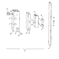
- Fig. 2 is a diagram showing a detail of a configuration of the ultrasonic motor 10.
- two drive elements 27 and 28 are mounted onto a layered piezoelectric element 26 oscillating by being applied by an electric signal, and the drive elements 27 and 28 are in contact with the slide plate 8 with a prescribed force.
- the drive elements 27 and 28 have a plane-to-plane contact respectively with the slide plate 8.
- one layered piezoelectric element 26 and two drive elements 27 and 28 constitute one ultrasonic oscillator.
- a support pin 29 is fixed onto the top surface of the layered piezoelectric element 26 with an adhesive, or such.
- a stationary member 30 is fixed onto the Y table 2 by screws, or such, going through fixing screw holes 31 and 32.
- the inside of the stationary member 30 is featured with a groove of a width allowing an insertion of a support member 33 so that the insertion of fixing pin 36 into respective fixing pin-use holes 34 and 35 in the state of the support member 33 being inserted into the groove part of the stationary member 30 fixes between the support member 33 and stationary member 30.
- the support member 33 is fixed onto the stationary member 30 rotatably against the stationary member 30 around the fixing pin 36 as axis.
- the support pin 29 fixed onto the top surface of the layered piezoelectric element 26 is supported without a play by a V-shaped support pin reception part 37 featured in the bottom of the support member 33.
- a pressure force with which the slide plate 8 and drive elements 27 and 28 are in contact with one another is applied by a pressure application member 38 such as a plunger.
- a male screw is usually formed on the periphery of the pressure application member 38. Therefore, the pressure application member 38 is screwed into a pressure application member-use tap 39 featured in the stationary member 30. As it is screwed in, the tip part of the pressure application member 38 is pressed against the top surface of the support member 33. In this case, the support member 33 rotates around the fixing pin 36.
- the ultrasonic motor 10 comprises a pressure application mechanism, that is, pressure application means, so that the drive elements 27 and 28 are pressed onto the slide plate 8 with a prescribed constant force as described above.
- the detail of the configuration of the ultrasonic motor is that one ultrasonic motor is equipped with the two drive elements 27 and 28 as described above. As a result, there are four contact spots between the slide plates 14 and 15 and the drive elements which are involved in a movement of the X table 3 because two ultrasonic motors 16 and 17 are placed opposite to the X table 3. Likewise, there are also four contact spots between the slide plates 8 and 9 and drive elements which are involved in a movement of the Y table 2.
- the microscope stage shown in Fig. 1 premises a use by fixing the stationary base 1 onto a microscope or such, and therefore the centers of the stationary base 1, Y table 2 and X table 3 are featured with opening parts 20, 21 and 22, respectively, so as to allow a passage of light. This prevents a barrier against a microscopic observation.
- the microscope stage according to the present embodiment is configured such that the two drive elements of the ultrasonic motor 10 contacts securely with the slide plate 8, and the two drive elements of the ultrasonic motor 11 contacts securely with the slide plate 9, within the moving range of the Y table 2 relative to the stationary base 1.
- the two drive elements of the ultrasonic motor 16 contacts securely with the slide plate 14, and the two drive elements of the ultrasonic motor 17 contacts securely with the slide plate 15, within the moving range of the X table 3 relative to the Y table 2.
- the present embodiment is configured such that the basic operation of the ultrasonic motors 10, 11, 16 and 17 when they are applied with an electric signal is the same as noted in the URL "http://www.olympus.co.jp/jp/crdc/tech/1997b/bm9712 00uslmj.cfm", for example.
- the sensor heads 13 and 19 use the optical linear encoder as noted in the Laid-Open Japanese Patent Application Publication No. H11-243258 , for example.
- an electric signal is applied to the ultrasonic motors 10 and 11.
- the application of the electric signal makes the ultrasonic motors 10 and 11 move on the slide plates 8 and 9.
- the ultrasonic motors 10 and 11 are fixed onto the Y table 2 which is supported by the first guides 4 and 5 allowing a movement in the Y direction relative to the stationary base 1, and therefore the Y table 2 moves in the Y direction.
- the movement amount is detected by the linear scale 12 and sensor head 13, enabling a calculation of an error against the target position.
- An electric signal is applied to the ultrasonic motors 10 and 11 until the error amount becomes no more than a target value, thereby moving the Y table 2 in the Y direction.
- the drive torque necessary for the movement is generated by the friction force by the contact of drive elements respectively equipped in the ultrasonic motors 10 and 11 with the slide plates 8 and 9, respectively.
- an electric signal is applied to the ultrasonic motors 16 and 17.
- the application of the electric signal makes the ultrasonic motors 16 and 17 move relatively on the slide plates 14 and 15.
- the ultrasonic motors 16 and 17 are fixed onto the X table 3 which is supported by the second guides 6 and 7 so as to allow a movement in the X direction relative to the Y table 2 and therefore the X table 3 moves in the X direction.
- the movement amount is detected by the linear scale 18 and sensor head 19, enabling a calculation of error against a target position.
- An electric signal is applied to the ultrasonic motors 16 and 17 until the error amount becomes no more than a target value, thereby moving the X table 3 in the X direction.
- the drive torque necessary for the movement is generated by the friction force by the contact of the drive elements respectively equipped in the ultrasonic motors 16 and 17 with the slide plates 14 and 15.
- the configuration and operation of the microscope stage as described above make it possible to alleviate an influence of a variation of friction force between the drive elements and slide plates, and move the table stably.
- the conventional motorized table apparatus there have been only two contact points between the drive elements and slide plates for one axis direction, creating the problem of the movement amount fluctuating greatly, resulting in degrading the operating characteristic as an X-Y table, if the friction force of either one of the contact points is varied for some reason.
- the microscope stage according to the present embodiment is configured such that the number of contact parts between the drive elements and slide plates increases to four for one axis direction and therefore, even if a fluctuation of friction force is caused in either one of the contact parts, a variation of the movement amount can be greatly reduced, thereby preventing a large degradation of the operating characteristic as an X-Y table.
- Fig. 3A is a diagram exemplifying an operating characteristic of a conventional motorized table apparatus in which there are only two contact points between a drive element and a slide plate for one axis direction; and Fig. 3B is a diagram exemplifying an operating characteristic of the microscope stage according to the embodiment 1 in which there are four contact parts between a drive element and a slide plate for one axis direction.
- Figs. 3A and 3B each shows an operating characteristic when an electric signal is applied so as to move a stage by 0.1 micrometers in one axis direction.
- the conventional motorized table apparatus allows a large fluctuation in an actual movement amount against the applied electric signal of 0.1 micrometers, whereas the microscope stage according to the present embodiment largely keeps the actual movement amount against the applied electric signal of 0. 1 micrometers, thus obtaining a good operating characteristic, as shown in Figs. 3A and 3B.
- a motorized table apparatus is a single axis stage in place of an X-Y two-axis stage; otherwise it is the same configuration and operation as the microscope stage according to the embodiment 1.
- Fig. 4 is a diagram showing a diagram showing a configuration of a motorized table apparatus according to the present embodiment.
- the motorized table apparatus comprises a stationary base 41 and a movement table 42 as major components, with the movement table 42 being supported so as to allow a movement in one axis direction relative to the stationary base 41 as shown in Fig. 4.
- What supports the movement table 42 so as to allow a movement in one axis direction are guides 43 (i.e., 43a and 43b) and 44 (i.e., 44a and 44b), which are support means such as a cross-roller guide, fixed onto the top surface of the stationary base 41 and the bottom surface of the movement table 42.
- the respective side surfaces of the guides 43b and 44b which are fixed onto the bottom surface of the movement table 42 are respectively attached with slide plates (i.e., the slide plate attached to the side surface of the guide 43b is not shown in a drawing herein, while the slide plate attached to the side surface of the guide 44b is the numeral 45).
- the attachment position of the slide plates are similar to the position described for the embodiment 1.
- the respective lengths of the slide plates in the longitudinal direction are equivalent to, or more than, the moving range of the movement table 42 relative to the stationary base 41.
- Ultrasonic motors 46 and 47 are placed so as to be fixed onto the top surface of the stationary base 41 and in contact with the slide plates, respectively. Such placements result in placing the ultrasonic motors 46 and 47 opposite to each other so as to sandwich the movement table 42.
- Fig. 4 shows a simplification of the ultrasonic motors 46 and 47, which are actually configured as the one shown in the above described Fig. 2.
- the linear scale 48 is fixed onto the side surface of the guide 44b fixed onto the bottom surface of the movement table 42.
- the mounting position of the linear scale 48 is also similar to the position described in the embodiment 1.
- the sensor head 49 is placed so as to be fixed onto the top surface of the stationary base 41 and opposite to the linear scale 48.
- the motorized table apparatus is configured such that the two drive elements of the ultrasonic motor 46 are securely in contact with the slide plate 45, and that the two drive elements of the ultrasonic motor 47 are securely in contact with a slide plate (not shown in a drawing herein), within the moving range of the movement table 42 relative to the stationary base 41.
- This is also basically similar to that of the microscope stage according to the embodiment 1. That is, when the movement table 42 is desired to move in one axis direction, an electric signal is applied to the ultrasonic motors 46 and 47. The application of the electric signal makes the ultrasonic motors 46 and 47 move relatively on the slide plates.
- the ultrasonic motors 46 and 47 are fixed onto the stationary base 41, and the movement table 42 is supported by the guides 43 and 44 so as to allow a movement in a single axis direction relative to the stationary base 41, and therefore the movement table 42 moves in the single axis direction.
- the movement amount is detected by the linear scale 48 and sensor head 49, enabling a calculation of an error against the target position.
- An electric signal is applied to the ultrasonic motors 46 and 47 until the error amount becomes no more than a target value, thereby moving the movement table 42 in the single axis direction.
- the drive torque necessary for the movement is generated by the friction force by the contact of drive elements respectively equipped in the ultrasonic motors 46 and 47 with the slide plates.
- the configuration and operation of the motorized table apparatus as described above make it possible to alleviate an influence of a variation of the friction force between the drive elements and slide plates, and drive the table stably likewise the microscope stage according to the embodiment 1.
- a motorized table apparatus is configured to place two ultrasonic motors lined up on one side, in place of them being opposite to each other, it is otherwise basically the same as the configuration and operation of the motorized table apparatus according to the embodiment 2.
- Fig. 5 is a diagram showing a configuration of a motorized table apparatus according to the present embodiment. Note that, in the showing Fig. 5, the same component sign is assigned to the same constituent component shown in Fig. 4.
- the motorized table apparatus is configured such that, associated with placing the two ultrasonic motors 46 and 47 lined up on one side, the linear scale 48 (not shown in Fig. 5) is fixed onto the side surface of the guide 43b fixed onto the bottom surface of the movement table 42 and the sensor head 49 is fixed onto the top surface of the stationary base 41 and is placed so as to be opposite to the linear scale 48 as shown in Fig. 5.
- a single slide plate 51 for the two ultrasonic motors 46 and 47 is fixed onto the guide 44b. It is otherwise configured similar to the motorized table apparatus according to the embodiment 2.
- a movement of the movement table 42 uses the two ultrasonic motors 46 and 47 placed by lining up on one side; it is otherwise similar to that of the motorized table apparatus according to the embodiment 2 and therefore the description is omitted here.
- the configuration and operation of the motorized table apparatus as described above make it possible to alleviate an influence of a variation of the friction force between the drive elements and slide plate and drive the table stably likewise the microscope stage according to the embodiment 2.
- the motorized table apparatus can also be configured to further elongate the longitudinal length of the slide plate 51 so that the entirety of the oscillators of the respective ultrasonic motors 46 and 47 are in contact with the slide plate 51 without fail within the moving range of the movement table 42 relative to the stationary base 41.
- the length in such a case is apparently the length equivalent to, or more than, the moving range of the movement table 42 relative to the station base 41.
- the present invention is contrived to enable an alleviation of degradation of an operating characteristic of a table due to a fluctuation of friction force at the contact part between the drive element and driven body of an ultrasonic oscillator and a stable movement of the table.
Landscapes
- Physics & Mathematics (AREA)
- Chemical & Material Sciences (AREA)
- Analytical Chemistry (AREA)
- General Physics & Mathematics (AREA)
- Optics & Photonics (AREA)
- Microscoopes, Condenser (AREA)
- General Electrical Machinery Utilizing Piezoelectricity, Electrostriction Or Magnetostriction (AREA)
- Details Of Measuring And Other Instruments (AREA)
- Container, Conveyance, Adherence, Positioning, Of Wafer (AREA)
Abstract
Description
- The present invention relates to a motorized table apparatus, such as a microscope stage, allowing a use in a field requiring a positioning.
- A conventional motorized table apparatus for use in a microscope (simply noted as "motorized table" hereinafter) employs in its drive unit a rotary motor, such as a stepping motor, and a motion transmission mechanism for converting a rotational drive force of the motor into a directional movement of a table. These motor and motion transmission mechanism need a large installation space, hence creating a problem of protruding from the upper surface and/or outer periphery of the table. As an example, if an observer who has been using a manual table apparatus (simply noted as "manual table" hereinafter) by covering with by a box, such as a thermal insulation box, limiting a space surrounding the table, or using a manual table by placing various apparatuses, such as a micro-manipulator and incubator wants to replace the manual table with a motorized table, the latter take a larger space than the former, and therefore it is difficult to simply replace the former.
- In order to solve such a problem, proposed is a motorized table using an ultrasonic wave actuator as represented by Laid-Open
Japanese Patent Application Publication Nos. 2005-265996 2000-28767 - An ultrasonic wave actuator performs a drive and a stop by a friction force in a contact part between a driven body and a friction member (i.e., a drive element) equipped on the actuator itself. Consequently, a variation of friction force at the contact part due to a change in contact state and a contamination results in changing a movement speed and a movement amount. There is a problem that, if there are a small number of contact points, a variation of friction force actually and drastically affects a movement characteristic of the table. As an example, there are only two contact points according to the conventional technique, and therefore a movement amount becomes half if the friction of either one of drive elements becomes zero causing a slip. When the movement amount varies as such, a problem occurs such as a time to arrive at a target position becoming very long, or an inability to position at the target position in the worst case.
- In consideration of the situation as described above, the purpose of the present invention is to provide a motorized table apparatus and a microscope stage which are capable of alleviating an influence of a friction force variation in a contact part between a drive element of an ultrasonic oscillator and a driven body and of moving a table stably.
- In order to achieve the above described purpose, a motorized table apparatus according to a first aspect of the present invention comprises a support unit for supporting a movement table so as to allow it to move in a single axis direction relative to a stationary unit which is fixed to the movement table; a slide member which is equipped on the movement table and which has a length equivalent to, or more than, a moving range of the movement table; an ultrasonic oscillator which is equipped on the stationary unit, which moves the movement table, and which comprises a single piezoelectric body and two drive elements; and a pressure application unit for supporting so that the two drive elements of the ultrasonic oscillator and the slide member are pressed by a constant force, wherein a plurality of the ultrasonic oscillators are equipped.
- A motorized table apparatus according to a second aspect of the present invention comprises a support unit for supporting a movement table so as to allow it to move in a single axis direction relative to a stationary unit which is fixed to the movement table; a slide member which is equipped on the stationary unit and which has a length equivalent to, or more than, a moving range of the movement table; an ultrasonic oscillator which is equipped on the movement table, which moves the movement table and which comprises a single piezoelectric body and two drive elements; and a pressure application unit for supporting so that the two drive elements of the ultrasonic oscillator and the slide member are pressed by a constant force, wherein a plurality of the ultrasonic oscillators are equipped.
-
- Fig. 1 is a diagram showing a configuration of a microscope stage which is a motorized table apparatus according to a
preferred embodiment 1; - Fig. 2 is a diagram showing a detail of a configuration of an ultrasonic motor;
- Fig. 3A is a diagram exemplifying an operating characteristic of a conventional motorized table in which there are only two contact points between a drive element and a slide plates for one axis direction;
- Fig. 3B is a diagram exemplifying an operating characteristic of the microscope stage according to the
embodiment 1 in which there are four contact points between a drive element and a slide plates for one axis direction; - Fig. 4 is a diagram showing a diagram showing a configuration of a motorized table apparatus according to a
preferred embodiment 2; and - Fig. 5 is a diagram showing a configuration of a motorized table apparatus according to a
preferred embodiment 3. - The following is a description of the preferred embodiment of the present invention by referring to the accompanying drawings.
- Fig. 1 is a diagram showing a configuration of a microscope stage which is a motorized table apparatus according to the
embodiment 1 of the present invention. - The microscope stage shown in Fig. 1 is roughly divided into a
stationary base 1, a Y table 2 and an X table 3, with the Y table 2 being supported so as to allow it to move in the Y direction relative to thestationary base 1, and the X table 3 being supported so as to allow it to move in the X direction relative to the Y table 2. Note that the Y table 2 can also be defined as a stationary unit which is fixed relative to the X table 3. - What support the Y table 2 so as to allow it to move in the Y direction are first guides 4 (i.e., 4a and 4b) and 5 (i.e., 5a and 5b) which are support means, such as cross roller guides, fixed onto the top surface of the
stationary base 1 and the bottom surface of the Y table 3, and what supports the X table 3 so as to allow it to move in the X direction are second guides 6 (i. e. , 6a and 6b) and 7 (i.e., 7a and 7b) which are support means, such as cross roller guides, fixed onto the top surface of the Y table 2 and the bottom surface of the X table 3. - Slide plates 8 and 9 are mounted onto the respective side surfaces of
first guides stationary base 1. The mounting positions of the slide plates 8 and 9 are preferably such that the longitudinal center line of the slides 8 and 9 is parallel with the moving direction of the Y table 2 and also on a plane which goes through the center line of the guide direction of the first andsecond guides stationary base 1. -
Ultrasonic motors ultrasonic motors stationary base 1. Note, Fig. 1 shows theultrasonic motors - A
linear scale 12 is fixed onto the side surface of thefirst guide 4a which is fixed onto thestationary base 1. While the mounting position of thelinear scale 12 is such that the center line of thelinear scale 12 in the longitudinal direction is parallel with the moving direction of the Y table 2 and also on the plane going through the center line of the respective guide directions of thefirst guides linear scale 12 is fixed onto thestationary base 1 in parallel with the moving direction of the Y table 2. - A
sensor head 13 is placed so as to be fixed to the bottom surface of the Y table 2 and opposite to thelinear scale 12. -
Slide plates second guides slide plates slide plates second guides slide plates -
Ultrasonic motors 16 and 17 are placed so as to be fixed onto the top surface of the Y table 2 and in contact with theslide plates ultrasonic motors 16 and 17 placed opposite so as to sandwich the X table 3. Note, Fig. 1 also shows theultrasonic motors 16 and 17 in simplification; they are actually configured as shown in a later described Fig. 2, however. - A
linear scale 18 is fixed onto the side surface of thesecond guide 7b which is fixed onto the X table 3. While the mounting position of thelinear scale 18 is such that the center line of thelinear scale 18 in the longitudinal direction is parallel with the moving direction of the X table 3 and also on the plane going through the center line of the respective guide directions of thesecond guides linear scale 18 is fixed onto the X table 3 in parallel with the moving direction thereof. - A
sensor head 19 is placed so as to be fixed onto the top surface of the Y table 2 and opposite to thelinear scale 18. - Here, the description is on a configuration of the ultrasonic motor in detail by referring to Fig. 2. The present embodiment is configured to use the same configuration for the
ultrasonic motors ultrasonic motor 10 represent them. - Fig. 2 is a diagram showing a detail of a configuration of the
ultrasonic motor 10. - Referring to Fig. 2, two
drive elements piezoelectric element 26 oscillating by being applied by an electric signal, and thedrive elements drive elements piezoelectric element 26 and twodrive elements support pin 29 is fixed onto the top surface of the layeredpiezoelectric element 26 with an adhesive, or such. - Meanwhile, a
stationary member 30 is fixed onto the Y table 2 by screws, or such, going through fixingscrew holes stationary member 30 is featured with a groove of a width allowing an insertion of a support member 33 so that the insertion offixing pin 36 into respective fixing pin-use holes stationary member 30 fixes between the support member 33 andstationary member 30. In this case, the support member 33 is fixed onto thestationary member 30 rotatably against thestationary member 30 around thefixing pin 36 as axis. - The
support pin 29 fixed onto the top surface of the layeredpiezoelectric element 26 is supported without a play by a V-shaped supportpin reception part 37 featured in the bottom of the support member 33. A pressure force with which the slide plate 8 anddrive elements pressure application member 38 such as a plunger. A male screw is usually formed on the periphery of thepressure application member 38. Therefore, thepressure application member 38 is screwed into a pressure application member-use tap 39 featured in thestationary member 30. As it is screwed in, the tip part of thepressure application member 38 is pressed against the top surface of the support member 33. In this case, the support member 33 rotates around the fixingpin 36. This rotation results in pressing thesupport pin 29 which is in contact with the V-shaped supportpin reception part 37 featured at the bottom surface of the support member 33 in the same direction as the pressing direction of thepressure application member 38. Associated with this, thesupport pin 29, layeredpiezoelectric element 26 and driveelements drive elements pressure application member 38 further increases the pressing force. Theultrasonic motor 10 comprises a pressure application mechanism, that is, pressure application means, so that thedrive elements - The detail of the configuration of the ultrasonic motor is that one ultrasonic motor is equipped with the two
drive elements slide plates ultrasonic motors 16 and 17 are placed opposite to the X table 3. Likewise, there are also four contact spots between the slide plates 8 and 9 and drive elements which are involved in a movement of the Y table 2. - Meanwhile, the microscope stage shown in Fig. 1 premises a use by fixing the
stationary base 1 onto a microscope or such, and therefore the centers of thestationary base 1, Y table 2 and X table 3 are featured with openingparts - Note that the microscope stage according to the present embodiment is configured such that the two drive elements of the
ultrasonic motor 10 contacts securely with the slide plate 8, and the two drive elements of theultrasonic motor 11 contacts securely with the slide plate 9, within the moving range of the Y table 2 relative to thestationary base 1. Likewise, the two drive elements of theultrasonic motor 16 contacts securely with theslide plate 14, and the two drive elements of the ultrasonic motor 17 contacts securely with theslide plate 15, within the moving range of the X table 3 relative to the Y table 2. - The next is a description on operations of the tables of the microscope stage.
- Note that the present embodiment is configured such that the basic operation of the
ultrasonic motors Japanese Patent Application Publication No. H11-243258 - When the Y table 2 is desired to move in the Y direction on the microscope stage, an electric signal is applied to the
ultrasonic motors ultrasonic motors ultrasonic motors stationary base 1, and therefore the Y table 2 moves in the Y direction. The movement amount is detected by thelinear scale 12 andsensor head 13, enabling a calculation of an error against the target position. An electric signal is applied to theultrasonic motors ultrasonic motors - Meanwhile, when the X table 3 is desired to move in the X direction, an electric signal is applied to the
ultrasonic motors 16 and 17. The application of the electric signal makes theultrasonic motors 16 and 17 move relatively on theslide plates ultrasonic motors 16 and 17 are fixed onto the X table 3 which is supported by the second guides 6 and 7 so as to allow a movement in the X direction relative to the Y table 2 and therefore the X table 3 moves in the X direction. The movement amount is detected by thelinear scale 18 andsensor head 19, enabling a calculation of error against a target position. An electric signal is applied to theultrasonic motors 16 and 17 until the error amount becomes no more than a target value, thereby moving the X table 3 in the X direction. The drive torque necessary for the movement is generated by the friction force by the contact of the drive elements respectively equipped in theultrasonic motors 16 and 17 with theslide plates - The configuration and operation of the microscope stage as described above make it possible to alleviate an influence of a variation of friction force between the drive elements and slide plates, and move the table stably. In the conventional motorized table apparatus, there have been only two contact points between the drive elements and slide plates for one axis direction, creating the problem of the movement amount fluctuating greatly, resulting in degrading the operating characteristic as an X-Y table, if the friction force of either one of the contact points is varied for some reason. Contrarily, the microscope stage according to the present embodiment is configured such that the number of contact parts between the drive elements and slide plates increases to four for one axis direction and therefore, even if a fluctuation of friction force is caused in either one of the contact parts, a variation of the movement amount can be greatly reduced, thereby preventing a large degradation of the operating characteristic as an X-Y table.
- The description at this time is on a difference of operating characteristics between the conventional motorized table apparatus, which has only two contacts points between the drive elements and slide plates for one axis direction, and the microscope stage according to the present embodiment, which has four contact parts between the drive elements and slide plates for one axis direction, by referring to Figs. 3A and 3B.
- Fig. 3A is a diagram exemplifying an operating characteristic of a conventional motorized table apparatus in which there are only two contact points between a drive element and a slide plate for one axis direction; and Fig. 3B is a diagram exemplifying an operating characteristic of the microscope stage according to the
embodiment 1 in which there are four contact parts between a drive element and a slide plate for one axis direction. Figs. 3A and 3B each shows an operating characteristic when an electric signal is applied so as to move a stage by 0.1 micrometers in one axis direction. - The conventional motorized table apparatus allows a large fluctuation in an actual movement amount against the applied electric signal of 0.1 micrometers, whereas the microscope stage according to the present embodiment largely keeps the actual movement amount against the applied electric signal of 0. 1 micrometers, thus obtaining a good operating characteristic, as shown in Figs. 3A and 3B.
- A motorized table apparatus according to the
embodiment 2 of the present invention is a single axis stage in place of an X-Y two-axis stage; otherwise it is the same configuration and operation as the microscope stage according to theembodiment 1. - Fig. 4 is a diagram showing a diagram showing a configuration of a motorized table apparatus according to the present embodiment.
- The motorized table apparatus comprises a
stationary base 41 and a movement table 42 as major components, with the movement table 42 being supported so as to allow a movement in one axis direction relative to thestationary base 41 as shown in Fig. 4. What supports the movement table 42 so as to allow a movement in one axis direction are guides 43 (i.e., 43a and 43b) and 44 (i.e., 44a and 44b), which are support means such as a cross-roller guide, fixed onto the top surface of thestationary base 41 and the bottom surface of the movement table 42. - The respective side surfaces of the
guides guide 43b is not shown in a drawing herein, while the slide plate attached to the side surface of theguide 44b is the numeral 45). The attachment position of the slide plates are similar to the position described for theembodiment 1. The respective lengths of the slide plates in the longitudinal direction are equivalent to, or more than, the moving range of the movement table 42 relative to thestationary base 41. -
Ultrasonic motors stationary base 41 and in contact with the slide plates, respectively. Such placements result in placing theultrasonic motors ultrasonic motors - The
linear scale 48 is fixed onto the side surface of theguide 44b fixed onto the bottom surface of the movement table 42. The mounting position of thelinear scale 48 is also similar to the position described in theembodiment 1. - The
sensor head 49 is placed so as to be fixed onto the top surface of thestationary base 41 and opposite to thelinear scale 48. - Note that the motorized table apparatus according to the present embodiment is configured such that the two drive elements of the
ultrasonic motor 46 are securely in contact with theslide plate 45, and that the two drive elements of theultrasonic motor 47 are securely in contact with a slide plate (not shown in a drawing herein), within the moving range of the movement table 42 relative to thestationary base 41. - The next is a description on a table operation of the motorized table apparatus according to the present embodiment. This is also basically similar to that of the microscope stage according to the
embodiment 1. That is, when the movement table 42 is desired to move in one axis direction, an electric signal is applied to theultrasonic motors ultrasonic motors ultrasonic motors stationary base 41, and the movement table 42 is supported by theguides stationary base 41, and therefore the movement table 42 moves in the single axis direction. The movement amount is detected by thelinear scale 48 andsensor head 49, enabling a calculation of an error against the target position. An electric signal is applied to theultrasonic motors ultrasonic motors - The configuration and operation of the motorized table apparatus as described above make it possible to alleviate an influence of a variation of the friction force between the drive elements and slide plates, and drive the table stably likewise the microscope stage according to the
embodiment 1. - A motorized table apparatus according to the
embodiment 3 of the present invention is configured to place two ultrasonic motors lined up on one side, in place of them being opposite to each other, it is otherwise basically the same as the configuration and operation of the motorized table apparatus according to theembodiment 2. - Fig. 5 is a diagram showing a configuration of a motorized table apparatus according to the present embodiment. Note that, in the showing Fig. 5, the same component sign is assigned to the same constituent component shown in Fig. 4.
- The motorized table apparatus according to the present embodiment is configured such that, associated with placing the two
ultrasonic motors guide 43b fixed onto the bottom surface of the movement table 42 and thesensor head 49 is fixed onto the top surface of thestationary base 41 and is placed so as to be opposite to thelinear scale 48 as shown in Fig. 5. Asingle slide plate 51 for the twoultrasonic motors guide 44b. It is otherwise configured similar to the motorized table apparatus according to theembodiment 2. - As for a table operation of the motorized table apparatus configured as described above, a movement of the movement table 42 uses the two
ultrasonic motors embodiment 2 and therefore the description is omitted here. - The configuration and operation of the motorized table apparatus as described above make it possible to alleviate an influence of a variation of the friction force between the drive elements and slide plate and drive the table stably likewise the microscope stage according to the
embodiment 2. - Note that the motorized table apparatus according to the present embodiment can also be configured to further elongate the longitudinal length of the
slide plate 51 so that the entirety of the oscillators of the respectiveultrasonic motors slide plate 51 without fail within the moving range of the movement table 42 relative to thestationary base 41. The length in such a case is apparently the length equivalent to, or more than, the moving range of the movement table 42 relative to thestation base 41. - As such, the present invention has been described in detail, whereas the present invention can of course be improved or changed in various manners possible within the scope thereof in lieu of being limited to the above described embodiments.
- As described above, the present invention is contrived to enable an alleviation of degradation of an operating characteristic of a table due to a fluctuation of friction force at the contact part between the drive element and driven body of an ultrasonic oscillator and a stable movement of the table.
Claims (7)
- A motorized table apparatus, comprising:a support unit (6,7) for supporting a movement table (3) so as to allow it to move in a single axis direction relative to a stationary unit (2) which is fixed to the movement table (3);a slide member (14, 15) which is equipped on the movement table (3) and which has a length equivalent to, or more than, a moving range of the movement table (3);an ultrasonic oscillator (16, 17) which is equipped on the stationary unit (2), which moves the movement table (3) and which comprises a single piezoelectric body (26) and two drive elements (27, 28) ; anda pressure application unit (38) for supporting so that the two drive elements (27, 28) of the ultrasonic oscillator (16, 17) and the slide member (14, 15) are pressed by a constant force, whereina plurality of the ultrasonic oscillators (16, 17) are equipped.
- A motorized table apparatus, comprising:a support unit (4, 5) for supporting a movement table (2) so as to allow it to move in a single axis direction relative to a stationary unit (1) which is fixed to the movement table (2);a slide member (8, 9) which is equipped on the stationary unit (1) and which has a length equivalent to, or more than, a moving range of the movement table (2) ;an ultrasonic oscillator (10, 11) which is equipped on the movement table (2), which moves the movement table (2) and which comprises a single piezoelectric body (26) and two drive elements (27, 28) ; anda pressure application unit (38) for supporting so that the two drive elements (27, 28) of the ultrasonic oscillator (10, 11) and the slide member (8, 9) are pressed by a constant force, whereina plurality of the ultrasonic oscillators (10, 11) are equipped.
- The motorized table apparatus according to claim 1, wherein
the ultrasonic oscillator (16, 17) is placed opposite to the center line of a movement direction of the movement table (3). - The motorized table apparatus according to claim 2, wherein
the ultrasonic oscillator (10, 11) is placed opposite to the center line of a movement direction of the movement table (2). - The motorized table apparatus according to claim 1, wherein
the two drive elements (27, 28) of the ultrasonic oscillator (16, 17) have a plane-to-plane contact respectively with the slide member (14, 15). - The motorized table apparatus according to claim 2, wherein
the two drive elements (27, 28) of the ultrasonic oscillator (10, 11) have a plane-to-plane contact respectively with the slide member (14, 15). - A microscope stage, comprising:a stationary base (1) fixed to a microscope;a first movement table (2) movable along a first axis relative to the stationary base (1);a second movement table (3) movable along a second axis approximately perpendicular to the first axis relative to the first movement table (2);a first support unit (4, 5) for supporting the first movement table (2) so as to allow it to move in the first axis direction relative to the stationary base (1) ;a second support unit (6, 7) for supporting the second movement table (3) so as to allow it to move in the second axis direction relative to the first movement table (2);a first slide member (8, 9) which is equipped on the stationary base (1) and which has a length equivalent to, or more than, the moving range of the first movement table (2);a second slide member (14, 15) which is equipped on the second movement table (3) and which has a length equivalent to, or more than, the moving range of the second movement table (3);a first ultrasonic oscillator (10, 11) which is equipped on the first movement table (2), which moves the first movement table (2) in the first direction and which is constituted by a single piezoelectric body (26) and two drive elements (27, 28);a second ultrasonic oscillator (16, 17) which is equipped on the first movement table (2), which moves the second movement table (3) in the second direction and which is constituted by a single piezoelectric body (26) and two drive elements (27, 28);a first pressure application unit (38) for supporting the two dive elements (27, 28) of the first ultrasonic oscillator (10, 11) are pressed onto the first slide member (8, 9) at a certain force; anda second pressure application unit (38) for supporting the two dive elements (27, 28) of the second ultrasonic oscillator (16, 17) are pressed onto the second slide member (14, 15) at a certain force, whereina plurality of the first ultrasonic oscillators (10, 11) and that of the second ultrasonic oscillators (16, 17) are respectively equipped.
Applications Claiming Priority (1)
| Application Number | Priority Date | Filing Date | Title |
|---|---|---|---|
| JP2006189331A JP2008014913A (en) | 2006-07-10 | 2006-07-10 | Electric table device and microscope stage |
Publications (1)
| Publication Number | Publication Date |
|---|---|
| EP1879063A1 true EP1879063A1 (en) | 2008-01-16 |
Family
ID=38610519
Family Applications (1)
| Application Number | Title | Priority Date | Filing Date |
|---|---|---|---|
| EP07011570A Withdrawn EP1879063A1 (en) | 2006-07-10 | 2007-06-13 | Motorized table apparatus and microscope stage |
Country Status (3)
| Country | Link |
|---|---|
| US (1) | US7791796B2 (en) |
| EP (1) | EP1879063A1 (en) |
| JP (1) | JP2008014913A (en) |
Cited By (3)
| Publication number | Priority date | Publication date | Assignee | Title |
|---|---|---|---|---|
| WO2010018206A1 (en) * | 2008-08-15 | 2010-02-18 | Itk Dr. Kassen Gmbh | Positioning system |
| CN105094147A (en) * | 2014-04-23 | 2015-11-25 | 中国科学院物理研究所 | Precise actuating device |
| CN110010190A (en) * | 2019-04-30 | 2019-07-12 | 珠海澳大科技研究院 | Three-dimensional constant force parallel flexible mini positioning platform |
Families Citing this family (9)
| Publication number | Priority date | Publication date | Assignee | Title |
|---|---|---|---|---|
| DE112006003352B4 (en) * | 2005-12-06 | 2017-05-11 | Thk Co., Ltd. | XY table actuator |
| US8063383B2 (en) * | 2008-11-04 | 2011-11-22 | Sergiy Pryadkin | Inertial positioner and an optical instrument for precise positioning |
| USD632717S1 (en) | 2009-07-13 | 2011-02-15 | Maerzhaeuser Wetzlar Gmbh & Co. Kg | Microscope table |
| EP2488911B1 (en) * | 2009-10-16 | 2017-07-26 | Thorlabs, Inc. | Motorized stage |
| USD657407S1 (en) * | 2009-12-15 | 2012-04-10 | Sanyo Electric Co., Ltd. | Microscope |
| USD653274S1 (en) * | 2010-10-15 | 2012-01-31 | Thorlabs, Inc. | Motorized stage |
| TWI465008B (en) * | 2010-11-18 | 2014-12-11 | Htc Corp | Handheld electronic device |
| FR3046451B1 (en) * | 2016-01-06 | 2018-07-06 | Micro-Controle - Spectra-Physics | SYSTEM FOR GENERATING DISPLACEMENT OF A SUPPORT PLATE ACCORDING TO SIX DEGREES OF FREEDOM. |
| JP7805858B2 (en) * | 2022-05-13 | 2026-01-26 | 株式会社日立ハイテク | Stage device, charged particle beam device and vacuum device |
Citations (5)
| Publication number | Priority date | Publication date | Assignee | Title |
|---|---|---|---|---|
| JPH07181277A (en) * | 1993-12-24 | 1995-07-21 | Olympus Optical Co Ltd | Drive |
| EP0938144A2 (en) | 1998-02-20 | 1999-08-25 | Seiko Instruments Inc. | Stage utilizing ultrasonic motor and printer utilizing the stage |
| JP2000028767A (en) | 1998-07-08 | 2000-01-28 | Kyocera Corp | Linear guide device |
| US20030201695A1 (en) * | 2002-04-03 | 2003-10-30 | Olympus Optical Co., Ltd. | Ultrasonic linear motor |
| JP2005265996A (en) | 2004-03-16 | 2005-09-29 | Olympus Corp | Microscopic stage |
Family Cites Families (5)
| Publication number | Priority date | Publication date | Assignee | Title |
|---|---|---|---|---|
| DE19940124C2 (en) * | 1998-08-31 | 2003-04-10 | Olympus Optical Co | Platform with a displacement enhancement mechanism |
| JP3523510B2 (en) * | 1998-11-30 | 2004-04-26 | 京セラ株式会社 | Linear guide device |
| US7180662B2 (en) * | 2004-04-12 | 2007-02-20 | Applied Scientific Instrumentation Inc. | Stage assembly and method for optical microscope including Z-axis stage and piezoelectric actuator for rectilinear translation of Z stage |
| JP4689993B2 (en) * | 2004-09-07 | 2011-06-01 | オリンパス株式会社 | Vibration wave motor |
| JP2008136318A (en) * | 2006-11-29 | 2008-06-12 | Olympus Corp | Ultrasonic motor and microscope stage |
-
2006
- 2006-07-10 JP JP2006189331A patent/JP2008014913A/en active Pending
-
2007
- 2007-06-13 EP EP07011570A patent/EP1879063A1/en not_active Withdrawn
- 2007-06-20 US US11/820,740 patent/US7791796B2/en not_active Expired - Fee Related
Patent Citations (5)
| Publication number | Priority date | Publication date | Assignee | Title |
|---|---|---|---|---|
| JPH07181277A (en) * | 1993-12-24 | 1995-07-21 | Olympus Optical Co Ltd | Drive |
| EP0938144A2 (en) | 1998-02-20 | 1999-08-25 | Seiko Instruments Inc. | Stage utilizing ultrasonic motor and printer utilizing the stage |
| JP2000028767A (en) | 1998-07-08 | 2000-01-28 | Kyocera Corp | Linear guide device |
| US20030201695A1 (en) * | 2002-04-03 | 2003-10-30 | Olympus Optical Co., Ltd. | Ultrasonic linear motor |
| JP2005265996A (en) | 2004-03-16 | 2005-09-29 | Olympus Corp | Microscopic stage |
Cited By (5)
| Publication number | Priority date | Publication date | Assignee | Title |
|---|---|---|---|---|
| WO2010018206A1 (en) * | 2008-08-15 | 2010-02-18 | Itk Dr. Kassen Gmbh | Positioning system |
| CN105094147A (en) * | 2014-04-23 | 2015-11-25 | 中国科学院物理研究所 | Precise actuating device |
| EP3136399A4 (en) * | 2014-04-23 | 2017-04-12 | Institute Of Physics Chinese Academy Of Sciences | Precision actuating device |
| CN110010190A (en) * | 2019-04-30 | 2019-07-12 | 珠海澳大科技研究院 | Three-dimensional constant force parallel flexible mini positioning platform |
| CN110010190B (en) * | 2019-04-30 | 2021-11-16 | 珠海澳大科技研究院 | Three-dimensional constant force parallel flexible micro-positioning platform |
Also Published As
| Publication number | Publication date |
|---|---|
| JP2008014913A (en) | 2008-01-24 |
| US7791796B2 (en) | 2010-09-07 |
| US20080043325A1 (en) | 2008-02-21 |
Similar Documents
| Publication | Publication Date | Title |
|---|---|---|
| US7791796B2 (en) | Motorized table apparatus and microscope stage | |
| JP4674218B2 (en) | Lens transfer device | |
| JP5191999B2 (en) | Optical structure unit | |
| JP6214193B2 (en) | Vibration wave drive device, two-dimensional drive device, image shake correction device, interchangeable lens, imaging device, and automatic stage | |
| JP6305377B2 (en) | Vibrating actuator, device and optical instrument | |
| CN107210687A (en) | The micro, slight type motor mounting of integrated form | |
| US8638026B2 (en) | Stage drive device | |
| AU2005263777A1 (en) | Geodesic measuring instrument with a piezo drive | |
| US7141914B2 (en) | Micromanipulator including piezoelectric benders | |
| JP4945587B2 (en) | Piezoelectric motor, electronic device with piezoelectric motor, and stage equipped with piezoelectric motor | |
| JP4328575B2 (en) | Positioning mechanism using vibration type drive | |
| JP6152019B2 (en) | Linear drive unit using ultrasonic motor | |
| JP6949905B2 (en) | Actuators, devices | |
| CN121028315B (en) | Four-degree-of-freedom flexible adjusting structure | |
| JP2018088821A (en) | Vibrating actuator, device and optical instrument | |
| JPH06194579A (en) | Stage with adjustable fine movement | |
| JP2005265996A (en) | Microscopic stage | |
| JP3347658B2 (en) | Tables and their driving units | |
| JP2010041762A (en) | Drive device | |
| KR100507840B1 (en) | Dual servo xy stage using leaf spring guide | |
| JP5142974B2 (en) | Switching mechanism by ultrasonic transducer | |
| JP7077107B2 (en) | Vibration actuators and devices with vibration actuators | |
| JP2025059704A (en) | Vibration actuator, optical device, and electronic device | |
| EP1758217A2 (en) | Optical apparatus having a laser light source unit, and image recording apparatus | |
| JP5395363B2 (en) | Positioning device |
Legal Events
| Date | Code | Title | Description |
|---|---|---|---|
| PUAI | Public reference made under article 153(3) epc to a published international application that has entered the european phase |
Free format text: ORIGINAL CODE: 0009012 |
|
| AK | Designated contracting states |
Kind code of ref document: A1 Designated state(s): AT BE BG CH CY CZ DE DK EE ES FI FR GB GR HU IE IS IT LI LT LU LV MC MT NL PL PT RO SE SI SK TR |
|
| AX | Request for extension of the european patent |
Extension state: AL BA HR MK YU |
|
| 17P | Request for examination filed |
Effective date: 20080716 |
|
| 17Q | First examination report despatched |
Effective date: 20080814 |
|
| AKX | Designation fees paid |
Designated state(s): DE |
|
| STAA | Information on the status of an ep patent application or granted ep patent |
Free format text: STATUS: THE APPLICATION IS DEEMED TO BE WITHDRAWN |
|
| 18D | Application deemed to be withdrawn |
Effective date: 20140103 |