EP1878874A2 - Integral main body-tip microcircuite for blades - Google Patents
Integral main body-tip microcircuite for blades Download PDFInfo
- Publication number
- EP1878874A2 EP1878874A2 EP07252702A EP07252702A EP1878874A2 EP 1878874 A2 EP1878874 A2 EP 1878874A2 EP 07252702 A EP07252702 A EP 07252702A EP 07252702 A EP07252702 A EP 07252702A EP 1878874 A2 EP1878874 A2 EP 1878874A2
- Authority
- EP
- European Patent Office
- Prior art keywords
- leg
- turbine engine
- engine component
- component according
- cooling
- Prior art date
- Legal status (The legal status is an assumption and is not a legal conclusion. Google has not performed a legal analysis and makes no representation as to the accuracy of the status listed.)
- Granted
Links
- 238000001816 cooling Methods 0.000 claims abstract description 54
- 239000002826 coolant Substances 0.000 claims abstract description 27
- 239000012530 fluid Substances 0.000 claims description 9
- 239000012809 cooling fluid Substances 0.000 claims description 5
- 238000004891 communication Methods 0.000 claims description 4
- 239000000463 material Substances 0.000 description 3
- 238000000034 method Methods 0.000 description 3
- 239000003870 refractory metal Substances 0.000 description 3
- 229910000601 superalloy Inorganic materials 0.000 description 3
- XEEYBQQBJWHFJM-UHFFFAOYSA-N Iron Chemical compound [Fe] XEEYBQQBJWHFJM-UHFFFAOYSA-N 0.000 description 2
- PXHVJJICTQNCMI-UHFFFAOYSA-N Nickel Chemical compound [Ni] PXHVJJICTQNCMI-UHFFFAOYSA-N 0.000 description 2
- 238000002955 isolation Methods 0.000 description 2
- RTAQQCXQSZGOHL-UHFFFAOYSA-N Titanium Chemical compound [Ti] RTAQQCXQSZGOHL-UHFFFAOYSA-N 0.000 description 1
- WYTGDNHDOZPMIW-RCBQFDQVSA-N alstonine Natural products C1=CC2=C3C=CC=CC3=NC2=C2N1C[C@H]1[C@H](C)OC=C(C(=O)OC)[C@H]1C2 WYTGDNHDOZPMIW-RCBQFDQVSA-N 0.000 description 1
- 238000005266 casting Methods 0.000 description 1
- 238000010276 construction Methods 0.000 description 1
- 229910052742 iron Inorganic materials 0.000 description 1
- 239000002184 metal Substances 0.000 description 1
- 229910052751 metal Inorganic materials 0.000 description 1
- 229910052759 nickel Inorganic materials 0.000 description 1
- 238000005086 pumping Methods 0.000 description 1
- 239000010936 titanium Substances 0.000 description 1
- 229910052719 titanium Inorganic materials 0.000 description 1
Images


Classifications
-
- F—MECHANICAL ENGINEERING; LIGHTING; HEATING; WEAPONS; BLASTING
- F01—MACHINES OR ENGINES IN GENERAL; ENGINE PLANTS IN GENERAL; STEAM ENGINES
- F01D—NON-POSITIVE DISPLACEMENT MACHINES OR ENGINES, e.g. STEAM TURBINES
- F01D5/00—Blades; Blade-carrying members; Heating, heat-insulating, cooling or antivibration means on the blades or the members
- F01D5/12—Blades
- F01D5/14—Form or construction
- F01D5/18—Hollow blades, i.e. blades with cooling or heating channels or cavities; Heating, heat-insulating or cooling means on blades
- F01D5/186—Film cooling
-
- F—MECHANICAL ENGINEERING; LIGHTING; HEATING; WEAPONS; BLASTING
- F05—INDEXING SCHEMES RELATING TO ENGINES OR PUMPS IN VARIOUS SUBCLASSES OF CLASSES F01-F04
- F05D—INDEXING SCHEME FOR ASPECTS RELATING TO NON-POSITIVE-DISPLACEMENT MACHINES OR ENGINES, GAS-TURBINES OR JET-PROPULSION PLANTS
- F05D2230/00—Manufacture
- F05D2230/20—Manufacture essentially without removing material
- F05D2230/21—Manufacture essentially without removing material by casting
-
- F—MECHANICAL ENGINEERING; LIGHTING; HEATING; WEAPONS; BLASTING
- F05—INDEXING SCHEMES RELATING TO ENGINES OR PUMPS IN VARIOUS SUBCLASSES OF CLASSES F01-F04
- F05D—INDEXING SCHEME FOR ASPECTS RELATING TO NON-POSITIVE-DISPLACEMENT MACHINES OR ENGINES, GAS-TURBINES OR JET-PROPULSION PLANTS
- F05D2250/00—Geometry
- F05D2250/10—Two-dimensional
- F05D2250/18—Two-dimensional patterned
- F05D2250/185—Two-dimensional patterned serpentine-like
-
- Y—GENERAL TAGGING OF NEW TECHNOLOGICAL DEVELOPMENTS; GENERAL TAGGING OF CROSS-SECTIONAL TECHNOLOGIES SPANNING OVER SEVERAL SECTIONS OF THE IPC; TECHNICAL SUBJECTS COVERED BY FORMER USPC CROSS-REFERENCE ART COLLECTIONS [XRACs] AND DIGESTS
- Y02—TECHNOLOGIES OR APPLICATIONS FOR MITIGATION OR ADAPTATION AGAINST CLIMATE CHANGE
- Y02T—CLIMATE CHANGE MITIGATION TECHNOLOGIES RELATED TO TRANSPORTATION
- Y02T50/00—Aeronautics or air transport
- Y02T50/60—Efficient propulsion technologies, e.g. for aircraft
Definitions
- the present invention relates to a cooling microcircuit for use in a turbine engine component such as a turbine blade.
- prior art turbine blades have a plurality of cavities with each blade internal cavity feeding a cooling microcircuit located on a side of the airfoil, either on a pressure side or on a suction side.
- a cooling microcircuit located on a side of the airfoil, either on a pressure side or on a suction side.
- the flow in the internal supply cavities assume relatively low Mach number distribution when compared to more conventional serpentine cooling designs. Due to these low Mach numbers, the rotational forces, resulting from the angular speeds of the rotor, become predominant. This, in turn, induces a series of cavity vortices inside the supply cavities. Since the internal cavities supply coolant air to the microcircuits embedded in the wall, the location of these supply links, between cavity and microcircuit, become extremely important.
- FIGS. 1 and 2 there is shown an airfoil with embedded wall circuits having cooling supply flows from a large internal cavity.
- the embedded circuits on the pressure side would experience a relative lower flow compared to those on the suction side.
- the cooling effectiveness is much lower on the pressure side than on the suction side.
- the simpler option is the second option above where a blade is designed to have dedicated and independent cooling supplies to each microcircuit.
- the microcircuit flow cooling characteristics are then de-sensitized from potential high rotational effects and other interferences.
- seven internal large cavities were cored for the turbine blade of FIG. 1, leading to six internal ribs within the airfoil portion.
- the existence of several cold ribs is particularly significant for this application, as cold ribs provide increased creep capability for the airfoil.
- FIGS. 3 - 5 the direct relationship of one microcircuit per supply cavity leads to potential assembly issues when microcircuit cores are tied-in with the main-body cores of the supply cavities during the pre-casting operation.
- the cooling microcircuit is a separate and independent circuit.
- a turbine engine component which broadly comprises an airfoil portion having a tip, a root portion, and a cooling microcircuit arrangement within the airfoil portion.
- the cooling microcircuit arrangement comprises a multi-leg main body portion for allowing a flow of coolant to convectively cool the airfoil portion and at least one integrally formed tip cooling microcircuit for cooling the tip of the airfoil portion.
- FIG. 6 To solve the problem of core assembly, while taking advantage of the isolation of each microcircuit from a total independent supply, the cooling scheme of FIG. 6 is presented.
- a turbine engine component 10 such as a turbine blade, having an airfoil portion 12, a platform 14, and a root portion 16.
- the airfoil portion 12 has a tip 18.
- a cooling microcircuit 20 is imbedded within the airfoil portion 12.
- the imbedded cooling microcircuit 20 receives a coolant flow stream from an inlet 24 formed within the root portion 16.
- the inlet 24 is preferably positioned adjacent a leading edge of the root portion 16.
- the inlet 24 may communicate with any suitable source of cooling fluid such as engine bleed air.
- the coolant flow stream is allowed to flow radially upward (in a direction away from the platform 14) through a first leg 26 of the cooling microcircuit 20 so as to take advantage of the natural pumping force.
- the cooling microcircuit 20 may have a serpentine configuration.
- the tip cooling circuit 30 comprises a plurality of spaced apart flow passages 70.
- Each flow passage 70 has an inlet which may communicate with and receive coolant from the first leg 26 as well as from a U-shaped flow turn portion 34 connecting the legs 26 and 28.
- the cooling microcircuit 30 may be provided with a third leg 36 in which the coolant flows radially upward.
- the tip circuit 32 also may comprise a plurality of spaced apart flow passages 72.
- Each flow passage 72 may have an inlet which communicates with the third leg 36 of the cooling microcircuit 20 so as to receive coolant therefrom.
- Each cooling circuit passage 70 and 72 has a fluid outlet or exit 33 which allows cooling fluid to flow over a surface of the airfoil portion 12.
- the exits 33 are configured to allow the coolant to exit on the pressure side 35 of the airfoil portion 12.
- the tip cooling exits 33 from the circuits 30 and 32 may extend from a point near the leading edge 44 to a point near the trailing edge 50 of the airfoil portion 12.
- a root inlet refresher leg 38 may be fabricated within the root portion 16.
- the root inlet refresher leg 38 is in fluid communication with the third leg 36 and may be used to insure adequate cooling flow in the third leg 36.
- the root inlet refresher leg 38 may communicate with any suitable source (not shown) of cooling fluid such as engine bleed air.
- exit tabs 40 forming film slots 42 may be provided in the legs 26 and/or 28.
- the exit tabs 40 and film slots 42 allow coolant fluid to flow from the legs 26 and/or 28 onto a surface of the airfoil portion.
- the surface may be the pressure side surface 35 or the suction side surface 37. Fluid exiting the slots 42 helps form a cooling film over one or more of the exterior surfaces of the turbine engine component 10.
- Such film slots 42 may be useful in an open-cooling system.
- the leading edge 44 of the airfoil portion 12 may be provided with a plurality of fluid outlets or exits 46 which allow a film of coolant to flow over the leading edge portions of the pressure side 35 and the suction side 37 of the airfoil portion 12.
- the outlets or exits 46 may be supplied with coolant from a supply cavity 48.
- the supply cavity 48 may communicate directly with a source (not shown) of cooling fluid, such as engine bleed air, or alternatively, the supply cavity 48 may be in fluid communication with the first leg 26.
- the cooling microcircuit of the present invention may also be used in a closed loop system without film cooling for industrial gas turbine applications where the external thermal load is not as high as that for aircraft engine applications.
- the cooling microcircuit arrangement of the present invention may be formed using any suitable technique known in the art.
- one or more sheets formed from a refractory metal material may be configured in the shape of the cooling microcircuit arrangement 20 including the inlet 24 and the root inlet refresher leg 38, the legs 26, 28, and 36, the tip cooling microcircuits 30 and 32, the exits 33, the tabs 40, and the film slots 42.
- the refractory metal material sheets may be placed or positioned within a mold cavity.
- the turbine engine component 10 including the airfoil portion 12, the platform 14, and the root portion 16 may be cast from any suitable metal known in the art such as a nickel based superalloy, a titanium based superalloy, or an iron based superalloy.
- the refractory metal material sheets may be removed using any suitable means known in the art, leaving the cooling microcircuit arrangement 20 of the present invention.
Abstract
Description
- The present invention relates to a cooling microcircuit for use in a turbine engine component such as a turbine blade.
- As it can be appreciated from FIGS. 1 and 2, prior art turbine blades have a plurality of cavities with each blade internal cavity feeding a cooling microcircuit located on a side of the airfoil, either on a pressure side or on a suction side. For blade cooling designs with double wall construction, or imbedded microcircuits in the airfoils, such as those illustrated in FIGS. 1 and 2, the flow in the internal supply cavities assume relatively low Mach number distribution when compared to more conventional serpentine cooling designs. Due to these low Mach numbers, the rotational forces, resulting from the angular speeds of the rotor, become predominant. This, in turn, induces a series of cavity vortices inside the supply cavities. Since the internal cavities supply coolant air to the microcircuits embedded in the wall, the location of these supply links, between cavity and microcircuit, become extremely important.
- There are two possible ways to solve this problem. First, one can determine the characteristics of these in-plane secondary vortices in a way so as to facilitate access of the cooling air into the microcircuits. Second, one can de-sensitize the microcircuit cooling to the supply links by having one supply cavity per microcircuit. If neither of these options is followed, a concern exists of having multiple feeds from one internal cavity to more than one microcircuit, which would lead to a flow imbalance.
- In the FIGS. 1 and 2, there is shown an airfoil with embedded wall circuits having cooling supply flows from a large internal cavity. In the configuration shown, the embedded circuits on the pressure side would experience a relative lower flow compared to those on the suction side. As a result the cooling effectiveness is much lower on the pressure side than on the suction side.
- The simpler option is the second option above where a blade is designed to have dedicated and independent cooling supplies to each microcircuit. As a result, the microcircuit flow cooling characteristics are then de-sensitized from potential high rotational effects and other interferences. As a consequence of this cooling design philosophy, seven internal large cavities were cored for the turbine blade of FIG. 1, leading to six internal ribs within the airfoil portion. The existence of several cold ribs is particularly significant for this application, as cold ribs provide increased creep capability for the airfoil. However, as illustrated in FIGS. 3 - 5, the direct relationship of one microcircuit per supply cavity leads to potential assembly issues when microcircuit cores are tied-in with the main-body cores of the supply cavities during the pre-casting operation. In addition, the cooling microcircuit is a separate and independent circuit.
- Thus, there remains a problem of core assembly to be solved when designing cooling microcircuits for turbine engine components such as turbine blades.
- In accordance with the present invention, there is provided a solution to the core assembly problem which also takes advantage of the isolation of each microcircuit from a total independent supply.
- In accordance with the present invention, there is provided a turbine engine component which broadly comprises an airfoil portion having a tip, a root portion, and a cooling microcircuit arrangement within the airfoil portion. The cooling microcircuit arrangement comprises a multi-leg main body portion for allowing a flow of coolant to convectively cool the airfoil portion and at least one integrally formed tip cooling microcircuit for cooling the tip of the airfoil portion.
- Other details of the integral main body-tip microcircuits for blades of the present invention, as well as other advantages attendant thereto, are set forth in the following detailed description and the accompanying drawings wherein like reference numerals depict like elements.
-
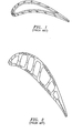
- FIG. 1 is an illustration of a prior art turbine blade having internal blade cavities for separate imbedded airfoil wall microcircuits;
- FIG. 2 is an illustration of a prior art turbine blade having dedicated supply cavities per microcircuit to avoid cooling effectiveness debits;
- FIG. 3 is an illustration of a portion of a prior art turbine blade having three pressure side microcircuits;
- FIG. 4 is an illustration of a portion of a prior art turbine blade having two suction side microcircuits;
- FIG. 5 is an illustration of a prior art turbine blade having a trailing edge microcircuit; and
- FIG. 6 is an illustration of a turbine blade having a serpentine airfoil microcircuit supplied from the blade root and integrated main mid-body with tip microcircuit as one unit.
- To solve the problem of core assembly, while taking advantage of the isolation of each microcircuit from a total independent supply, the cooling scheme of FIG. 6 is presented. As shown in this figure, there is provided a
turbine engine component 10, such as a turbine blade, having anairfoil portion 12, aplatform 14, and aroot portion 16. Theairfoil portion 12 has atip 18. Acooling microcircuit 20 is imbedded within theairfoil portion 12. The imbeddedcooling microcircuit 20 receives a coolant flow stream from aninlet 24 formed within theroot portion 16. Theinlet 24 is preferably positioned adjacent a leading edge of theroot portion 16. Theinlet 24 may communicate with any suitable source of cooling fluid such as engine bleed air. The coolant flow stream is allowed to flow radially upward (in a direction away from the platform 14) through afirst leg 26 of thecooling microcircuit 20 so as to take advantage of the natural pumping force. As can be seen from FIG. 6, thecooling microcircuit 20 may have a serpentine configuration. Thus, as the coolant flow stream reaches the vicinity of thetip 18 of theairfoil portion 12, the coolant flow bends and proceeds to asecond leg 28. Within thesecond leg 28, the coolant flows radially downward (in a direction toward the platform 14). In this arrangement, some bypass coolant flow may be used to cool thetip 18 viatip cooling circuits tip cooling circuit 30 comprises a plurality of spaced apartflow passages 70. Eachflow passage 70 has an inlet which may communicate with and receive coolant from thefirst leg 26 as well as from a U-shapedflow turn portion 34 connecting thelegs - The
cooling microcircuit 30 may be provided with athird leg 36 in which the coolant flows radially upward. Thetip circuit 32 also may comprise a plurality of spaced apartflow passages 72. Eachflow passage 72 may have an inlet which communicates with thethird leg 36 of thecooling microcircuit 20 so as to receive coolant therefrom. Eachcooling circuit passage exit 33 which allows cooling fluid to flow over a surface of theairfoil portion 12. Preferably, theexits 33 are configured to allow the coolant to exit on thepressure side 35 of theairfoil portion 12. Thetip cooling exits 33 from thecircuits edge 44 to a point near thetrailing edge 50 of theairfoil portion 12. By providing the cooling microcircuit arrangement described herein, three separate circuits make up one unit and thus facilitate the assembly process. - A root
inlet refresher leg 38 may be fabricated within theroot portion 16. The rootinlet refresher leg 38 is in fluid communication with thethird leg 36 and may be used to insure adequate cooling flow in thethird leg 36. The rootinlet refresher leg 38 may communicate with any suitable source (not shown) of cooling fluid such as engine bleed air. - As can be seen from the foregoing description, an integral main body and
tip microcircuit arrangement 20 has been provided. Theturbine engine component 10 is cooled convectively in this way. - If desired,
exit tabs 40 formingfilm slots 42 may be provided in thelegs 26 and/or 28. Theexit tabs 40 andfilm slots 42 allow coolant fluid to flow from thelegs 26 and/or 28 onto a surface of the airfoil portion. The surface may be thepressure side surface 35 or thesuction side surface 37. Fluid exiting theslots 42 helps form a cooling film over one or more of the exterior surfaces of theturbine engine component 10.Such film slots 42 may be useful in an open-cooling system. - If desired, the leading
edge 44 of theairfoil portion 12 may be provided with a plurality of fluid outlets or exits 46 which allow a film of coolant to flow over the leading edge portions of thepressure side 35 and thesuction side 37 of theairfoil portion 12. The outlets or exits 46 may be supplied with coolant from asupply cavity 48. Thesupply cavity 48 may communicate directly with a source (not shown) of cooling fluid, such as engine bleed air, or alternatively, thesupply cavity 48 may be in fluid communication with thefirst leg 26. - The cooling microcircuit of the present invention may also be used in a closed loop system without film cooling for industrial gas turbine applications where the external thermal load is not as high as that for aircraft engine applications.
- The cooling microcircuit arrangement of the present invention may be formed using any suitable technique known in the art. In a preferred method of forming the cooling microcircuit, one or more sheets formed from a refractory metal material may be configured in the shape of the cooling
microcircuit arrangement 20 including theinlet 24 and the rootinlet refresher leg 38, thelegs tip cooling microcircuits exits 33, thetabs 40, and thefilm slots 42. The refractory metal material sheets may be placed or positioned within a mold cavity. Thereafter, theturbine engine component 10 including theairfoil portion 12, theplatform 14, and theroot portion 16 may be cast from any suitable metal known in the art such as a nickel based superalloy, a titanium based superalloy, or an iron based superalloy. After the turbine engine component has been cast, the refractory metal material sheets may be removed using any suitable means known in the art, leaving the coolingmicrocircuit arrangement 20 of the present invention.
Claims (16)
- A turbine engine component (10) comprising:an airfoil portion (12) having a tip (18) and a root portion (16);a cooling microcircuit arrangement (20) within said airfoil portion (12); andsaid cooling microcircuit arrangement (20) comprising a multi-leg main body portion for allowing a flow of coolant to convectively cool said airfoil portion (12) and at least one integrally formed tip cooling microcircuit (30,32).
- The turbine engine component according to claim 1, wherein said multi-leg main body portion comprises a serpentine cooling arrangement.
- The turbine engine component according to claim 1 or 2, further comprising a coolant inlet (24) extending through said root portion (16) and communicating with said multi-leg main body portion.
- The turbine engine component according to claim 3, wherein said coolant inlet (24) is located adjacent a leading edge of said root portion (16).
- The turbine engine component according to claim 3 or 4, wherein said multi-leg main body portion has a first leg (26) which allows coolant from said coolant inlet (24) to flow radially upwards towards said tip (18).
- The turbine engine component according to claim 5, further comprising said at least one integrally formed cooling microcircuit (30) being in fluid communication with said first leg (26).
- The turbine engine component according to claim 5, further comprising a plurality of integrally formed cooling microcircuits (30) being in fluid communication with said first leg (26).
- The turbine engine component according to any of claims 5 to 7, wherein said multi-leg main body portion has a second leg (28) which receives coolant from said first leg (26) and in which said coolant flows radially downward.
- The turbine engine component according to claim 8, further comprising a plurality of film cooling slots (42) located between said first leg (26) and said second leg (28) for allowing coolant to flow over a surface of said airfoil portion (12).
- The turbine engine component according to claim 8 or 9, further comprising said multi-leg main body portion having a third leg (36) in which coolant moves radially upward.
- The turbine engine component according to claim 10, further comprising a refresher inlet (38) extending within said root portion (16) and supplying coolant to said third leg (36).
- The turbine engine component according to claim 10 or 11, further comprising said at least one tip cooling microcircuit (32) communicating with said third leg (36).
- The turbine engine component according to claim 10 or 11, further comprising a plurality of tip cooling microcircuits (32) communicating with said third leg (36).
- The turbine engine component according to any preceding claim, wherein each said tip cooling microcircuit (30,32) has an exit for allowing cooling fluid to flow over a pressure side surface (35) of said airfoil portion (12).
- The turbine engine component according to any preceding claim, further comprising a platform (14) positioned intermediate said airfoil portion (12) and said root portion (16).
- The turbine engine component according to any preceding claim, further comprising said airfoil portion (12) having a leading edge (44), a pressure side wall (35), and a suction side wall (37), and said leading edge (44) having a plurality of fluid outlets (46) for allowing said coolant to flow over at least one of a leading edge portion of the pressure side wall and a leading edge portion of the suction side wall.
Applications Claiming Priority (1)
| Application Number | Priority Date | Filing Date | Title |
|---|---|---|---|
| US11/484,143 US20080008599A1 (en) | 2006-07-10 | 2006-07-10 | Integral main body-tip microcircuits for blades |
Publications (3)
| Publication Number | Publication Date |
|---|---|
| EP1878874A2 true EP1878874A2 (en) | 2008-01-16 |
| EP1878874A3 EP1878874A3 (en) | 2011-05-25 |
| EP1878874B1 EP1878874B1 (en) | 2012-06-27 |
Family
ID=38461959
Family Applications (1)
| Application Number | Title | Priority Date | Filing Date |
|---|---|---|---|
| EP07252702A Active EP1878874B1 (en) | 2006-07-10 | 2007-07-05 | Integral main body-tip microcircuit for blades |
Country Status (3)
| Country | Link |
|---|---|
| US (1) | US20080008599A1 (en) |
| EP (1) | EP1878874B1 (en) |
| JP (1) | JP2008019861A (en) |
Cited By (3)
| Publication number | Priority date | Publication date | Assignee | Title |
|---|---|---|---|---|
| EP1927414A3 (en) * | 2006-11-30 | 2008-07-30 | United Technologies Corporation | RMC-Defined tip blowing slots for turbine blades |
| EP2223753A1 (en) | 2009-02-17 | 2010-09-01 | United Technologies Corporation | Process and refractory metal core for creating varying thickness microcircuits for turbine engine components |
| EP2385216A3 (en) * | 2010-05-06 | 2014-02-19 | United Technologies Corporation | Turbine airfoil with body microcircuits terminating in platform |
Families Citing this family (12)
| Publication number | Priority date | Publication date | Assignee | Title |
|---|---|---|---|---|
| US8157527B2 (en) | 2008-07-03 | 2012-04-17 | United Technologies Corporation | Airfoil with tapered radial cooling passage |
| US8572844B2 (en) | 2008-08-29 | 2013-11-05 | United Technologies Corporation | Airfoil with leading edge cooling passage |
| US8303252B2 (en) | 2008-10-16 | 2012-11-06 | United Technologies Corporation | Airfoil with cooling passage providing variable heat transfer rate |
| US8109725B2 (en) | 2008-12-15 | 2012-02-07 | United Technologies Corporation | Airfoil with wrapped leading edge cooling passage |
| US9429027B2 (en) | 2012-04-05 | 2016-08-30 | United Technologies Corporation | Turbine airfoil tip shelf and squealer pocket cooling |
| US9422817B2 (en) | 2012-05-31 | 2016-08-23 | United Technologies Corporation | Turbine blade root with microcircuit cooling passages |
| WO2015060989A1 (en) | 2013-10-24 | 2015-04-30 | United Technologies Corporation | Lost core molding cores for forming cooling passages |
| WO2015126488A2 (en) | 2013-12-23 | 2015-08-27 | United Technologies Corporation | Lost core structural frame |
| US10508554B2 (en) | 2015-10-27 | 2019-12-17 | General Electric Company | Turbine bucket having outlet path in shroud |
| US9885243B2 (en) | 2015-10-27 | 2018-02-06 | General Electric Company | Turbine bucket having outlet path in shroud |
| US10156145B2 (en) * | 2015-10-27 | 2018-12-18 | General Electric Company | Turbine bucket having cooling passageway |
| US10787932B2 (en) * | 2018-07-13 | 2020-09-29 | Honeywell International Inc. | Turbine blade with dust tolerant cooling system |
Citations (4)
| Publication number | Priority date | Publication date | Assignee | Title |
|---|---|---|---|---|
| EP1101899A1 (en) * | 1999-11-18 | 2001-05-23 | United Technologies Corporation | Method and apparatus for cooling an airfoil |
| EP1288439A1 (en) * | 2001-08-28 | 2003-03-05 | Snecma Moteurs | Cooling fluid flow configuration for a gas turbine blade |
| EP1445424A2 (en) * | 2003-02-05 | 2004-08-11 | United Technologies Corporation | Microcircuit cooling for a turbine blade tip |
| EP1577498A1 (en) * | 2004-03-16 | 2005-09-21 | United Technologies Corporation | Microcircuit cooling for a turbine airfoil |
Family Cites Families (2)
| Publication number | Priority date | Publication date | Assignee | Title |
|---|---|---|---|---|
| US7334991B2 (en) * | 2005-01-07 | 2008-02-26 | Siemens Power Generation, Inc. | Turbine blade tip cooling system |
| US7431562B2 (en) * | 2005-12-21 | 2008-10-07 | General Electric Company | Method and apparatus for cooling gas turbine rotor blades |
-
2006
- 2006-07-10 US US11/484,143 patent/US20080008599A1/en not_active Abandoned
-
2007
- 2007-06-27 JP JP2007168349A patent/JP2008019861A/en active Pending
- 2007-07-05 EP EP07252702A patent/EP1878874B1/en active Active
Patent Citations (4)
| Publication number | Priority date | Publication date | Assignee | Title |
|---|---|---|---|---|
| EP1101899A1 (en) * | 1999-11-18 | 2001-05-23 | United Technologies Corporation | Method and apparatus for cooling an airfoil |
| EP1288439A1 (en) * | 2001-08-28 | 2003-03-05 | Snecma Moteurs | Cooling fluid flow configuration for a gas turbine blade |
| EP1445424A2 (en) * | 2003-02-05 | 2004-08-11 | United Technologies Corporation | Microcircuit cooling for a turbine blade tip |
| EP1577498A1 (en) * | 2004-03-16 | 2005-09-21 | United Technologies Corporation | Microcircuit cooling for a turbine airfoil |
Cited By (6)
| Publication number | Priority date | Publication date | Assignee | Title |
|---|---|---|---|---|
| EP1927414A3 (en) * | 2006-11-30 | 2008-07-30 | United Technologies Corporation | RMC-Defined tip blowing slots for turbine blades |
| EP2246133A1 (en) * | 2006-11-30 | 2010-11-03 | United Technologies Corporation | RMC-defined tip blowing slots for turbine blades |
| EP2223753A1 (en) | 2009-02-17 | 2010-09-01 | United Technologies Corporation | Process and refractory metal core for creating varying thickness microcircuits for turbine engine components |
| US8347947B2 (en) | 2009-02-17 | 2013-01-08 | United Technologies Corporation | Process and refractory metal core for creating varying thickness microcircuits for turbine engine components |
| US9038700B2 (en) | 2009-02-17 | 2015-05-26 | United Technologies Corporation | Process and refractory metal core for creating varying thickness microcircuits for turbine engine components |
| EP2385216A3 (en) * | 2010-05-06 | 2014-02-19 | United Technologies Corporation | Turbine airfoil with body microcircuits terminating in platform |
Also Published As
| Publication number | Publication date |
|---|---|
| EP1878874B1 (en) | 2012-06-27 |
| US20080008599A1 (en) | 2008-01-10 |
| EP1878874A3 (en) | 2011-05-25 |
| JP2008019861A (en) | 2008-01-31 |
Similar Documents
| Publication | Publication Date | Title |
|---|---|---|
| EP1878874B1 (en) | Integral main body-tip microcircuit for blades | |
| US7744347B2 (en) | Peripheral microcircuit serpentine cooling for turbine airfoils | |
| US9797261B2 (en) | Internal cooling of engine components | |
| EP1070829B1 (en) | Internally cooled airfoil | |
| EP1927414B1 (en) | RMC-Defined tip blowing slots for turbine blades | |
| EP2565383B1 (en) | Airfoil with cooling passage | |
| US8057183B1 (en) | Light weight and highly cooled turbine blade | |
| US7722327B1 (en) | Multiple vortex cooling circuit for a thin airfoil | |
| EP1900904B1 (en) | Multi-peripheral serpentine microcircuits for high aspect ratio blades | |
| EP1865151A2 (en) | Microcircuit cooling for blades | |
| US7967563B1 (en) | Turbine blade with tip section cooling channel | |
| KR20070078974A (en) | Microcircuits for small engines | |
| EP1939400A2 (en) | Airfoil cooling with staggered refractory metal cores forming microcircuits | |
| EP1882820A1 (en) | Microcircuit cooling and blade tip blowing | |
| EP2022941B1 (en) | Turbine blade of a gas turbine engine | |
| JP2008144760A (en) | Turbine engine component, and method for forming airfoil portion of turbine engine component | |
| JP2007218262A5 (en) | ||
| US8186953B1 (en) | Multiple piece turbine blade | |
| JP2008032006A (en) | Radially split serpentine microcircuit | |
| US20160245097A1 (en) | Airfoil and method for manufacturing an airfoil | |
| JP2012036888A (en) | Bucket assembly cooling apparatus and method for forming the bucket assembly | |
| JP2007170392A (en) | Airfoil for rotor blade, and turbine blade | |
| WO2014108318A1 (en) | Blade for a turbomachine | |
| WO2014106598A1 (en) | Blade for a turbomachine |
Legal Events
| Date | Code | Title | Description |
|---|---|---|---|
| PUAI | Public reference made under article 153(3) epc to a published international application that has entered the european phase |
Free format text: ORIGINAL CODE: 0009012 |
|
| AK | Designated contracting states |
Kind code of ref document: A2 Designated state(s): AT BE BG CH CY CZ DE DK EE ES FI FR GB GR HU IE IS IT LI LT LU LV MC MT NL PL PT RO SE SI SK TR |
|
| AX | Request for extension of the european patent |
Extension state: AL BA HR MK YU |
|
| 17P | Request for examination filed |
Effective date: 20080114 |
|
| PUAL | Search report despatched |
Free format text: ORIGINAL CODE: 0009013 |
|
| AK | Designated contracting states |
Kind code of ref document: A3 Designated state(s): AT BE BG CH CY CZ DE DK EE ES FI FR GB GR HU IE IS IT LI LT LU LV MC MT NL PL PT RO SE SI SK TR |
|
| AX | Request for extension of the european patent |
Extension state: AL BA HR MK RS |
|
| RTI1 | Title (correction) |
Free format text: INTEGRAL MAIN BODY-TIP MICROCIRCUIT FOR BLADES |
|
| GRAP | Despatch of communication of intention to grant a patent |
Free format text: ORIGINAL CODE: EPIDOSNIGR1 |
|
| AKX | Designation fees paid |
Designated state(s): DE GB |
|
| GRAS | Grant fee paid |
Free format text: ORIGINAL CODE: EPIDOSNIGR3 |
|
| GRAA | (expected) grant |
Free format text: ORIGINAL CODE: 0009210 |
|
| AK | Designated contracting states |
Kind code of ref document: B1 Designated state(s): DE GB |
|
| REG | Reference to a national code |
Ref country code: GB Ref legal event code: FG4D |
|
| REG | Reference to a national code |
Ref country code: DE Ref legal event code: R096 Ref document number: 602007023562 Country of ref document: DE Effective date: 20120830 |
|
| PLBE | No opposition filed within time limit |
Free format text: ORIGINAL CODE: 0009261 |
|
| STAA | Information on the status of an ep patent application or granted ep patent |
Free format text: STATUS: NO OPPOSITION FILED WITHIN TIME LIMIT |
|
| 26N | No opposition filed |
Effective date: 20130328 |
|
| REG | Reference to a national code |
Ref country code: DE Ref legal event code: R097 Ref document number: 602007023562 Country of ref document: DE Effective date: 20130328 |
|
| REG | Reference to a national code |
Ref country code: DE Ref legal event code: R082 Ref document number: 602007023562 Country of ref document: DE Representative=s name: SCHMITT-NILSON SCHRAUD WAIBEL WOHLFROM PATENTA, DE |
|
| REG | Reference to a national code |
Ref country code: DE Ref legal event code: R082 Ref document number: 602007023562 Country of ref document: DE Representative=s name: SCHMITT-NILSON SCHRAUD WAIBEL WOHLFROM PATENTA, DE Ref country code: DE Ref legal event code: R081 Ref document number: 602007023562 Country of ref document: DE Owner name: UNITED TECHNOLOGIES CORP. (N.D.GES.D. STAATES , US Free format text: FORMER OWNER: UNITED TECHNOLOGIES CORP., HARTFORD, CONN., US |
|
| REG | Reference to a national code |
Ref country code: DE Ref legal event code: R081 Ref document number: 602007023562 Country of ref document: DE Owner name: RAYTHEON TECHNOLOGIES CORPORATION (N.D.GES.D.S, US Free format text: FORMER OWNER: UNITED TECHNOLOGIES CORP. (N.D.GES.D. STAATES DELAWARE), FARMINGTON, CONN., US |
|
| P01 | Opt-out of the competence of the unified patent court (upc) registered |
Effective date: 20230519 |
|
| PGFP | Annual fee paid to national office [announced via postgrant information from national office to epo] |
Ref country code: GB Payment date: 20230620 Year of fee payment: 17 |
|
| PGFP | Annual fee paid to national office [announced via postgrant information from national office to epo] |
Ref country code: DE Payment date: 20230620 Year of fee payment: 17 |