EP1878657A2 - Aircraft archway architecture - Google Patents
Aircraft archway architecture Download PDFInfo
- Publication number
- EP1878657A2 EP1878657A2 EP07021188A EP07021188A EP1878657A2 EP 1878657 A2 EP1878657 A2 EP 1878657A2 EP 07021188 A EP07021188 A EP 07021188A EP 07021188 A EP07021188 A EP 07021188A EP 1878657 A2 EP1878657 A2 EP 1878657A2
- Authority
- EP
- European Patent Office
- Prior art keywords
- aircraft
- archway
- archways
- members
- pair
- Prior art date
- Legal status (The legal status is an assumption and is not a legal conclusion. Google has not performed a legal analysis and makes no representation as to the accuracy of the status listed.)
- Granted
Links
Images


Classifications
-
- B—PERFORMING OPERATIONS; TRANSPORTING
- B64—AIRCRAFT; AVIATION; COSMONAUTICS
- B64D—EQUIPMENT FOR FITTING IN OR TO AIRCRAFT; FLIGHT SUITS; PARACHUTES; ARRANGEMENT OR MOUNTING OF POWER PLANTS OR PROPULSION TRANSMISSIONS IN AIRCRAFT
- B64D11/00—Passenger or crew accommodation; Flight-deck installations not otherwise provided for
-
- B—PERFORMING OPERATIONS; TRANSPORTING
- B64—AIRCRAFT; AVIATION; COSMONAUTICS
- B64C—AEROPLANES; HELICOPTERS
- B64C1/00—Fuselages; Constructional features common to fuselages, wings, stabilising surfaces or the like
- B64C1/06—Frames; Stringers; Longerons ; Fuselage sections
- B64C1/066—Interior liners
-
- B—PERFORMING OPERATIONS; TRANSPORTING
- B64—AIRCRAFT; AVIATION; COSMONAUTICS
- B64D—EQUIPMENT FOR FITTING IN OR TO AIRCRAFT; FLIGHT SUITS; PARACHUTES; ARRANGEMENT OR MOUNTING OF POWER PLANTS OR PROPULSION TRANSMISSIONS IN AIRCRAFT
- B64D11/00—Passenger or crew accommodation; Flight-deck installations not otherwise provided for
- B64D11/0023—Movable or removable cabin dividers, e.g. for class separation
-
- B—PERFORMING OPERATIONS; TRANSPORTING
- B64—AIRCRAFT; AVIATION; COSMONAUTICS
- B64D—EQUIPMENT FOR FITTING IN OR TO AIRCRAFT; FLIGHT SUITS; PARACHUTES; ARRANGEMENT OR MOUNTING OF POWER PLANTS OR PROPULSION TRANSMISSIONS IN AIRCRAFT
- B64D11/00—Passenger or crew accommodation; Flight-deck installations not otherwise provided for
- B64D11/02—Toilet fittings
-
- B—PERFORMING OPERATIONS; TRANSPORTING
- B64—AIRCRAFT; AVIATION; COSMONAUTICS
- B64D—EQUIPMENT FOR FITTING IN OR TO AIRCRAFT; FLIGHT SUITS; PARACHUTES; ARRANGEMENT OR MOUNTING OF POWER PLANTS OR PROPULSION TRANSMISSIONS IN AIRCRAFT
- B64D11/00—Passenger or crew accommodation; Flight-deck installations not otherwise provided for
- B64D11/06—Arrangements of seats, or adaptations or details specially adapted for aircraft seats
- B64D11/0691—Arrangements of seats, or adaptations or details specially adapted for aircraft seats specially adapted for cabin crew
-
- B—PERFORMING OPERATIONS; TRANSPORTING
- B64—AIRCRAFT; AVIATION; COSMONAUTICS
- B64D—EQUIPMENT FOR FITTING IN OR TO AIRCRAFT; FLIGHT SUITS; PARACHUTES; ARRANGEMENT OR MOUNTING OF POWER PLANTS OR PROPULSION TRANSMISSIONS IN AIRCRAFT
- B64D11/00—Passenger or crew accommodation; Flight-deck installations not otherwise provided for
- B64D2011/0046—Modular or preassembled units for creating cabin interior structures
Definitions
- the present invention relates to architectural structures for aircraft and more particularly to improved structures, cabin furnishing, accessories and auxiliary equipment for aircraft.
- the interior configuration and architecture of aircraft have become relatively standardized today.
- the arrangements of the passenger seats, bulkheads, lavatories, serving areas, and crew spaces have been developed for convenience and accommodation of both passengers and crew.
- the passenger compartments are typically divided into two or more sections with bulkheads and lavatories being positioned accordingly. Aisles and passageway spaces are left between sets of seats and at the access doors.
- the support lines and conduits for the accessory and auxiliary systems are typically positioned in the lower bay below the passenger compartment (cabin) or in the crown or space above the passenger cabin.
- the wires and lines are passed between the lower bay and crown, or between one of those areas and the passenger cabins through the sidewalls or support members adjacent the exterior of the aircraft.
- one or more arch-type members are positioned in the cabin of the aircraft.
- the archways preferably are inverted generally "U-shaped" structures which extend along the inside surfaces of the passenger cabins and have hollow interiors for placement and passage of electrical wires, air conditioning ducts, water lines and the like.
- the archways are placed at stable locations within the cabin, such as at fixed door locations, so that they will reduce potential impact on seat configurations.
- the archways provide a path or raceway for the system transport elements particularly between the crown and lower bays of the aircraft.
- the archways also can be positioned at architectural points of interest in the aircraft to help define and establish cabin proportions and also provide logical locations for passage of auxiliary system components. Placement of the archways at door locations provides a passage to run systems at each doorway without interfering with structural intercoastals located between framed bays at the door locations.
- the archways allow penetration through the floor of the cabin which can be standardized, reducing the variation in floor panel design.
- the archways can serve as receptacles for lavatory and gallery monuments, further reducing the complexity associated with integrating those elements into the interior of the aircraft.
- the archways further can eliminate the need for design close-out seals for outboard monuments.
- the present invention simplifies the installation complexity and eliminates the installation variability associated with installing and running transport elements between the crown and lower bays of the aircraft.
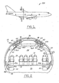
- FIGURE 1 illustrates an aircraft in which the present invention can be utilized.
- FIGURE 2 is a cross-section through the aircraft as shown in Figure 1 and depicting use of the present invention.
- FIGURE 3 is a perspective view of an aircraft cabin interior, illustrating the use of the present invention.
- FIGURE 4 is a perspective view illustrating the use of a plurality of archways in an aircraft in accordance with the present invention.
- FIGURE 5 depicts the use of a pair of inventive archways at an exterior door to the passenger compartment.
- FIGURE 6 is a cross-sectional view of the archways as shown in Figure 2.
- FIGURE 7 is a cross-section of an alternate embodiment of an archway in accordance with the present invention.
- FIGURE 8 is a cross-section of still another alternate embodiment of an archway in accordance with the present invention.
- FIGURE 9 illustrates use of the present invention for lavatories and other accessory systems.
- FIGURE 10 depicts a cross-section of still another alternate embodiment of an archway in accordance with the present invention.
- Efficient interior configuration and modification of airplanes and other aircraft is of value to airline companies and customers by reducing the costs associated with designing and installing cabin furnishings and auxiliary and support systems. Often, these activities will result in modifications to system transport elements, such as electrical wiring, water lines, or environment control system ducts resulting in increased costs and lead time for delivery of the desired aircraft. This problem is amplified for those transport elements that must run or be passed between the airplane crown and the lower lobe or bay, since current design practices result in loss of windows in the sidewalls, or longer than desired runs to fixed monuments at the fore or aft bulkheads.
- the complexity and costs associated with providing for system runs between the crown and lower bays of airplanes and other aircraft has a significant impact on interior architecture, interior flexibility, body structure at doorways and manufacturing installation time.
- the present invention simplifies the installation complexity and eliminates the installation variability associated with running transport elements between the crown and lower bay areas.
- the present invention uses architectural arches or archways at one or more locations along the length of the aircraft.
- the archways provide raceways or passageways for system transport elements, particularly for those which need to be passed from the crown to the lower bay of the aircraft.
- the archways also can be placed at stable locations within the fuselage or cabin of the aircraft, such as at fixed door locations which reduce the potential impact on seat configuration and provide improved cabin configurations.
- Archways located on either side of a doorway will enable a number of different functions, such as architectural delineation of cabin volumes that are properly proportioned, and enclosure of system transport elements, including, but not limited to, electrical power and signal, water and conditioned air.
- the architectural archways also can incorporate a stable floor coupling in order to pass system transporting elements through the floor while meeting existing requirements for floor penetrations.
- the inventive archways further will provide accommodation for items, including, but not limited to, system control panels, lavatories, emergency equipment and flight attendant seats.
- the archways When properly sized and configured, the archways will have the ability to provide for retractable features or otherwise hide these elements within the archway when not in use.
- an altered method for interior cabin lighting via recessed task lighting can result, particularly through the use of luminescent cover panels or wash lighting from within the archways.
- the present invention will also provide a way to more efficiently create and control air temperature zones within the cabin by using an archway located air curtain to prevent air draft from moving fore and aft between cabins.
- the present invention further can reduce the impact of external temperature extremes on cabin interior temperatures while in the boarding or deplaning processes.
- various stations or zones within the cabin can be designated where passengers can experience a local enhanced air environment contained within a station or zone. This could include local humidification, increased air mixing, or ionized/purified air.
- the present invention can provide a more integrated look for outboard lavatories or gallery monuments by designing the archways to accept the modules without the use of closeout seals or foams.
- system connections servicing these monuments can be readily accessible.
- archways located at doorways can serve as a system plenum to connect the systems that run between the crown of the airplane, the lower lobe or bay, and the main passenger cabin.
- the archways can assist in defining and establishing cabin proportions and also provide logical locations for system runs associated with water, power, and conditioned air.
- the placement at door locations provides a way to run systems at each doorway without having to interfere with the structural intercoastals located between frame bays typically positioned at door locations.
- the penetration through the floor can be standardized which will reduce the variation in floor panel designs.
- Figure 1 is a perspective view of an airplane or aircraft in which the present invention can be utilized.
- the airplane is referred to generally by the reference numeral 20.
- Figure 2 is a representative cross-section 2-2 taken at a location along the length of the fuselage or cabin of the airplane 20.
- the aircraft includes a main passenger cabin 24, an upper crown area 26 and a lower lobe or bay 28, all positioned with an outer skin or exterior 30 of the airplane.
- the lower bay 28 typically is utilized for transporting luggage and other material
- the passenger cabin or compartment 24 includes a number of passenger seats 32 which are positioned on a floor member 34 that extends across the width of the airplane 20.
- a number of luggage or storage bins 36A, 36B, and 36C are provided on the upper portion of the passenger cabin 24.
- An architectural arch or archway 40 is shown in its representative position within the airplane 20.
- the archway has a semi-circular or curved configuration as shown and is attached to the floor member 34 at its two lower ends 40A and 40B.
- the archway can be attached to the floor member in any conventional manner.
- the archway 40 preferably has a V-shaped cross-section as shown in Figure 6. Although a V-shaped cross-section is preferred, it is also possible within the scope of the present invention for the archway 40 to have other cross-sectional sizes and shapes.
- the archway 140 as shown in Figure 8, has an expanded U-shaped cross-sectional configuration and shape
- the archway 240 as shown in Figure 10 has a semi-circular or curved cross-sectional shape and configuration.
- an aircraft such as airplane 20, has a number of control, auxiliary and support systems which have wires and conduits which need to be passed or run along the length of the aircraft and to be utilized at various positions along the length of the aircraft. These lines and conduits also need to be passed at some locations between the crown and lower bay areas of the aircraft.
- the conduits for these systems are shown in Figure 2 and are represented generally by reference numerals 42, 44, 46, 48, and 50.
- the conduits and systems mentioned and shown are only representative of the known and conventional systems used in aircraft today, such as electrical wiring, control wiring, water lines, air ducts, environment control system ducts, etc.
- the system wires and conduits 42, 44, and 46 are positioned in the upper portion or crown 26 of the fuselage of the aircraft.
- other systems and conduits such as 48 and 50 shown in Figure 2
- the archways 40 of the present invention allow or act as passageways or chaseways for the electrical lines and other conduits, such as 42A, 44A, and 46A, 48A and 50A.
- the conduits are positioned in the interior open space of the archway 40.
- conduits or ducts be molded or provided as part of the archway itself. This is shown in Figure 7, where archway 40' has a cross member 54 which forms an enclosed plenum or chamber 56. It is also to be understood, of course, that any number of interior conduits and plenums can be provided in the archways in accordance with the present invention and thus the invention is not limited to a structure having at least one plenum or any number thereof.
- integral conduits or passageways do not have to extend the full length of the archway, but can be positioned only in one or more portions thereof, such as in the portions which are positioned along the inner sides of the aircraft fuselage. It is further possible to provide one or more archways for the aircraft which are not hollow at all, or are only hollow along portions thereof.
- pairs of arches or archways 40 can be positioned at various locations along the length of the aircraft or airplane. This is shown in Figures 3-5.
- An interior view of the fuselage 60 in the direction of the length of the fuselage is shown in Figure 3.
- the archways 40 are used to separate the fuselage into various cabins C1, C2, and C3 along the length of the airplane.
- FIG. 5 A side elevational view illustrating one of the pairs of archways 40A is shown in Figure 5.
- the pair of archways 40A are also used to frame a door member 62.
- various petitions 64 and 66 can be positioned in or adjacent to the archways 40, 40A in order to assist in separating the interior cabins, such as C1, C2 and C3, from one another.
- any number of archways can be provided along the length of the fuselage of an airplane or aircraft. It is also understood that any number of pairs or sets of archways can be provided at various locations along the length of the aircraft.
- archways in accordance with the present invention can also be used to house or accommodate various accessories or auxiliary systems which are common in passenger airplanes today.
- archways 80 and 82 are used to frame or flank a door member 62' at a location along the length of the airplane.
- Archway 80 is sufficiently wide to incorporate a lavatory 90, while archway 82 has a size sufficient to incorporate a jump seat 92 for one of the flight attendants.
- an archway can be modified to incorporate various other items and systems, such as telephone 94 and electronic controls 96 for other systems on the airplane.
- said archway is hollow and is adapted to run system components between said upper crown portion and said lower lobe portion, the system components being electrical wires, water lines or conditioned air ducts.
- said archway has a cross-sectional shape selected from the group comprising V-shaped, U-shaped and semi-circular shaped.
- the architectural archway for an aircraft further comprising at least one integral passageway in said archway structure for passage of a system component of the aircraft.
- the architectural archway for an aircraft further comprising a lavatory positioned in said archway structure adjacent one of said end members.
- the architectural archway for an aircraft further comprising a flight attendant seat member positioned in said archway structure.
- said end members of each of said archways are adapted to be positioned on the floor member on opposite sides of the fuselage.
- each of said archways is hollow and is adapted to run system components between said upper crown portion and said lower lobe portion, the system components being electrical wires, water lines or conditioned air ducts.
- each of said archways has a cross-sectional shape selected from the group comprising V-shaped, U-shaped and semi-circular shaped.
- the pair of architectural archways further comprising at least one integral passageway in said archway structure for passage of a system component of the aircraft.
- at least one of said pair of archway structures has a lavatory in it.
- at least one of said pair of archway structures has a flight attendant seat member in it.
- An aircraft having a fuselage for carrying passengers, said fuselage having an upper crown portion, a lower lobe portion, a passenger portion, a floor member in said passenger portion, at least one door member in said passenger portion, and at least one conduit from an aircraft support system, at least one archway member positioned in said passenger portion of said fuselage, said archway member having an inverted curved configuration with a curved central portion and two curved end portions, each of said curved end portions having an end member positioned on said floor member.
- said archway member has an internal hollow portion for positioning and passage of said conduit from said aircraft support system.
- said archway member has a cross-sectional shape selected from the group comprising V-shaped, U-shaped and semi-circular shaped.
- said aircraft has a plurality of support system conduits positioned in said crown portion and said lower lobe portion, and wherein at least apportion of said support system conduits are also positioned in said archway member.
- said aircraft has a plurality of support system conduits positioned in said crown portion and said lower lobe portion and wherein at least a portion of said support system components are passed between said upper crown portion and said lower lobe portion through said archway member.
- a pair of said archway members are positioned closely adjacent each other in said passenger portion and positioned adjacent to said door member.
- said pair of archway members are positioned on either side of said door member.
- At least two sets of archway members are positioned in said passenger portion, each set comprising a pair of archway members positioned closely adjacent each other.
- the archway member is utilized as a divider to separate said passenger portion into two separate sections.
- the archway member is utilized as a divider to separate said passenger portion from at least one flight service portion.
- the archway member has at least one integral passageway for positioning of said conduit.
- the aircraft further comprising a lavatory positioned in at least one curved end portion of said archway member.
- the aircraft further comprising a seat member positioned in at least one curved end portion of said archway member.
- the aircraft has a plurality of support system conduits positioned in said crown portion and said lower lobe portion, and wherein at least a portion of said support system components are passed from said upper lobe portion and into said passenger portion through said archway member.
- the aircraft has a plurality of support system conduits positioned in said crown portion and said lower lobe portion, and wherein at least a portion of said support system components are passed from said lower lobe portion and into said passenger portion through said archway member.
- the aircraft has a plurality of support system conduits positioned in said crown portion and said lower lobe portion, and wherein at least a portion of said support system components are passed between said upper crown portion and said lower lobe portion through said archway member.
- the support system is selected from the group comprising an electrical system, a water system and a conditioned air system.
Landscapes
- Engineering & Computer Science (AREA)
- Aviation & Aerospace Engineering (AREA)
- Mechanical Engineering (AREA)
- Electrical Discharge Machining, Electrochemical Machining, And Combined Machining (AREA)
- Ventilation (AREA)
- Pipeline Systems (AREA)
- Tents Or Canopies (AREA)
- Laminated Bodies (AREA)
- Exposure And Positioning Against Photoresist Photosensitive Materials (AREA)
Abstract
Description
- The present invention relates to architectural structures for aircraft and more particularly to improved structures, cabin furnishing, accessories and auxiliary equipment for aircraft.
- The interior configuration and architecture of aircraft have become relatively standardized today. The arrangements of the passenger seats, bulkheads, lavatories, serving areas, and crew spaces have been developed for convenience and accommodation of both passengers and crew. The passenger compartments are typically divided into two or more sections with bulkheads and lavatories being positioned accordingly. Aisles and passageway spaces are left between sets of seats and at the access doors.
- The support lines and conduits for the accessory and auxiliary systems, such as conditioned air, water, hydraulics and electrical systems, are typically positioned in the lower bay below the passenger compartment (cabin) or in the crown or space above the passenger cabin. For some of these accessory systems, such as conditioned air and electrical systems, the wires and lines are passed between the lower bay and crown, or between one of those areas and the passenger cabins through the sidewalls or support members adjacent the exterior of the aircraft.
- The installation, repair, and modification of the accessory and auxiliary systems, as well as the cabin furnishings, is a considerable expense to aircraft owners and users. There is a need for improved interior systems and for more efficient design and use of cabin furnishings and associated systems.
- Often, the design and installation of cabin furnishing and auxiliary systems result in modification to the system transport elements, such as electrical wiring, fluid lines, and environmental control system ducts, which result in an increased cost and lead time for delivery of the desired aircraft. The problem is amplified for those transport systems that pass between the crown and lower bay of the aircraft since this may result in the loss of windows and sidewalls or longer than desired runs to fixed monuments at bulkheads.
- There is a need in the aircraft industry for improved, more efficient, less complex, and less costly configurations for cabin furnishings and associated auxiliary systems in order to obviate the afore-mentioned problems.
- In accordance with the present invention, one or more arch-type members ("archways") are positioned in the cabin of the aircraft. The archways preferably are inverted generally "U-shaped" structures which extend along the inside surfaces of the passenger cabins and have hollow interiors for placement and passage of electrical wires, air conditioning ducts, water lines and the like. The archways are placed at stable locations within the cabin, such as at fixed door locations, so that they will reduce potential impact on seat configurations. The archways provide a path or raceway for the system transport elements particularly between the crown and lower bays of the aircraft.
- The archways also can be positioned at architectural points of interest in the aircraft to help define and establish cabin proportions and also provide logical locations for passage of auxiliary system components. Placement of the archways at door locations provides a passage to run systems at each doorway without interfering with structural intercoastals located between framed bays at the door locations. The archways allow penetration through the floor of the cabin which can be standardized, reducing the variation in floor panel design. In addition, the archways can serve as receptacles for lavatory and gallery monuments, further reducing the complexity associated with integrating those elements into the interior of the aircraft. The archways further can eliminate the need for design close-out seals for outboard monuments.
- The present invention simplifies the installation complexity and eliminates the installation variability associated with installing and running transport elements between the crown and lower bays of the aircraft.
- FIGURE 1 illustrates an aircraft in which the present invention can be utilized.
- FIGURE 2 is a cross-section through the aircraft as shown in Figure 1 and depicting use of the present invention.
- FIGURE 3 is a perspective view of an aircraft cabin interior, illustrating the use of the present invention.
- FIGURE 4 is a perspective view illustrating the use of a plurality of archways in an aircraft in accordance with the present invention.
- FIGURE 5 depicts the use of a pair of inventive archways at an exterior door to the passenger compartment.
- FIGURE 6 is a cross-sectional view of the archways as shown in Figure 2.
- FIGURE 7 is a cross-section of an alternate embodiment of an archway in accordance with the present invention.
- FIGURE 8 is a cross-section of still another alternate embodiment of an archway in accordance with the present invention.
- FIGURE 9 illustrates use of the present invention for lavatories and other accessory systems.
- FIGURE 10 depicts a cross-section of still another alternate embodiment of an archway in accordance with the present invention.
- Efficient interior configuration and modification of airplanes and other aircraft is of value to airline companies and customers by reducing the costs associated with designing and installing cabin furnishings and auxiliary and support systems. Often, these activities will result in modifications to system transport elements, such as electrical wiring, water lines, or environment control system ducts resulting in increased costs and lead time for delivery of the desired aircraft. This problem is amplified for those transport elements that must run or be passed between the airplane crown and the lower lobe or bay, since current design practices result in loss of windows in the sidewalls, or longer than desired runs to fixed monuments at the fore or aft bulkheads.
- The complexity and costs associated with providing for system runs between the crown and lower bays of airplanes and other aircraft has a significant impact on interior architecture, interior flexibility, body structure at doorways and manufacturing installation time. The present invention simplifies the installation complexity and eliminates the installation variability associated with running transport elements between the crown and lower bay areas.
- In particular, the present invention uses architectural arches or archways at one or more locations along the length of the aircraft. The archways provide raceways or passageways for system transport elements, particularly for those which need to be passed from the crown to the lower bay of the aircraft. The archways also can be placed at stable locations within the fuselage or cabin of the aircraft, such as at fixed door locations which reduce the potential impact on seat configuration and provide improved cabin configurations.
- Archways located on either side of a doorway will enable a number of different functions, such as architectural delineation of cabin volumes that are properly proportioned, and enclosure of system transport elements, including, but not limited to, electrical power and signal, water and conditioned air. The architectural archways also can incorporate a stable floor coupling in order to pass system transporting elements through the floor while meeting existing requirements for floor penetrations.
- The inventive archways further will provide accommodation for items, including, but not limited to, system control panels, lavatories, emergency equipment and flight attendant seats. When properly sized and configured, the archways will have the ability to provide for retractable features or otherwise hide these elements within the archway when not in use.
- With the present invention, an altered method for interior cabin lighting via recessed task lighting can result, particularly through the use of luminescent cover panels or wash lighting from within the archways. The present invention will also provide a way to more efficiently create and control air temperature zones within the cabin by using an archway located air curtain to prevent air draft from moving fore and aft between cabins.
- The present invention further can reduce the impact of external temperature extremes on cabin interior temperatures while in the boarding or deplaning processes.
- With the present invention, various stations or zones within the cabin can be designated where passengers can experience a local enhanced air environment contained within a station or zone. This could include local humidification, increased air mixing, or ionized/purified air.
- Finally, the present invention can provide a more integrated look for outboard lavatories or gallery monuments by designing the archways to accept the modules without the use of closeout seals or foams. In this regard, system connections servicing these monuments can be readily accessible.
- The use of archways located at doorways can serve as a system plenum to connect the systems that run between the crown of the airplane, the lower lobe or bay, and the main passenger cabin. The archways can assist in defining and establishing cabin proportions and also provide logical locations for system runs associated with water, power, and conditioned air. The placement at door locations provides a way to run systems at each doorway without having to interfere with the structural intercoastals located between frame bays typically positioned at door locations.
- With the present invention, the penetration through the floor can be standardized which will reduce the variation in floor panel designs.
- If the archways are used for lavatory and galley monuments, this can reduce the complexity associated with integrating these elements into the interior, as well as eliminating the need for designed closeout seals for outboard monuments.
- Figure 1 is a perspective view of an airplane or aircraft in which the present invention can be utilized. The airplane is referred to generally by the
reference numeral 20. - Figure 2 is a representative cross-section 2-2 taken at a location along the length of the fuselage or cabin of the
airplane 20. As indicated, the aircraft includes amain passenger cabin 24, anupper crown area 26 and a lower lobe orbay 28, all positioned with an outer skin orexterior 30 of the airplane. Thelower bay 28 typically is utilized for transporting luggage and other material The passenger cabin orcompartment 24 includes a number ofpassenger seats 32 which are positioned on afloor member 34 that extends across the width of theairplane 20. Also, as conventional in airplanes today, a number of luggage orstorage bins passenger cabin 24. - An architectural arch or
archway 40 is shown in its representative position within theairplane 20. The archway has a semi-circular or curved configuration as shown and is attached to thefloor member 34 at its twolower ends archway 40 preferably has a V-shaped cross-section as shown in Figure 6. Although a V-shaped cross-section is preferred, it is also possible within the scope of the present invention for thearchway 40 to have other cross-sectional sizes and shapes. For example, thearchway 140, as shown in Figure 8, has an expanded U-shaped cross-sectional configuration and shape, while thearchway 240 as shown in Figure 10 has a semi-circular or curved cross-sectional shape and configuration. - As shown in Figure 2, an aircraft, such as
airplane 20, has a number of control, auxiliary and support systems which have wires and conduits which need to be passed or run along the length of the aircraft and to be utilized at various positions along the length of the aircraft. These lines and conduits also need to be passed at some locations between the crown and lower bay areas of the aircraft. The conduits for these systems are shown in Figure 2 and are represented generally byreference numerals - With the configuration shown, the system wires and
conduits crown 26 of the fuselage of the aircraft. In addition, other systems and conduits, such as 48 and 50 shown in Figure 2, are positioned in the lower lobe or bay of the aircraft. In order to utilize these systems, thearchways 40 of the present invention allow or act as passageways or chaseways for the electrical lines and other conduits, such as 42A, 44A, and 46A, 48A and 50A. As shown in the cross-sectional view in Figure 6, the conduits are positioned in the interior open space of thearchway 40. Some of these same conduits and wires are also shown in Figures 8 and 10. - In accordance with the present invention, it is also possible to have one or more of the conduits or ducts be molded or provided as part of the archway itself. This is shown in Figure 7, where archway 40' has a
cross member 54 which forms an enclosed plenum orchamber 56. It is also to be understood, of course, that any number of interior conduits and plenums can be provided in the archways in accordance with the present invention and thus the invention is not limited to a structure having at least one plenum or any number thereof. - It is to be understood that the various cross-sectional sizes and shapes of the
archways - It is also possible to provide more than one integral or "built-in" conduit or passageway in the archway. Also, the integral conduits or passageways do not have to extend the full length of the archway, but can be positioned only in one or more portions thereof, such as in the portions which are positioned along the inner sides of the aircraft fuselage. It is further possible to provide one or more archways for the aircraft which are not hollow at all, or are only hollow along portions thereof.
- In accordance with one embodiment of the present invention, pairs of arches or
archways 40 can be positioned at various locations along the length of the aircraft or airplane. This is shown in Figures 3-5. First, as shown in Figure 4, two sets A, B of pairs ofarchways 40 are shown located at two positions in the fuselage ofairplane 120. An interior view of thefuselage 60 in the direction of the length of the fuselage is shown in Figure 3. Thearchways 40 are used to separate the fuselage into various cabins C1, C2, and C3 along the length of the airplane. - A side elevational view illustrating one of the pairs of
archways 40A is shown in Figure 5. The pair ofarchways 40A are also used to frame adoor member 62. In this regard, as shown in Figures 3 and 5,various petitions archways - It is to be understood in accordance with the present invention, that any number of archways can be provided along the length of the fuselage of an airplane or aircraft. It is also understood that any number of pairs or sets of archways can be provided at various locations along the length of the aircraft.
- As shown in Figure 9, archways in accordance with the present invention can also be used to house or accommodate various accessories or auxiliary systems which are common in passenger airplanes today. In this regard, archways 80 and 82 are used to frame or flank a door member 62' at a location along the length of the airplane.
Archway 80 is sufficiently wide to incorporate alavatory 90, whilearchway 82 has a size sufficient to incorporate ajump seat 92 for one of the flight attendants. Also, as shown in Figure 9, an archway can be modified to incorporate various other items and systems, such astelephone 94 and electronic controls 96 for other systems on the airplane.
An architectural archway for an aircraft having an elongated fuselage with an upper crown portion, a floor member and a lower lobe portion, said archway comprising a curved inverted hoop-like structure with two spaced apart end members, said structure adapted to fit inside the fuselage and be positioned on the floor member with said end members positioned on the floor member on opposite sides of the fuselage.
Preferably said archway is hollow and is adapted to run system components between said upper crown portion and said lower lobe portion, the system components being electrical wires, water lines or conditioned air ducts.
Preferably said archway has a cross-sectional shape selected from the group comprising V-shaped, U-shaped and semi-circular shaped.
The architectural archway for an aircraft further comprising at least one integral passageway in said archway structure for passage of a system component of the aircraft.
The architectural archway for an aircraft further comprising a lavatory positioned in said archway structure adjacent one of said end members.
The architectural archway for an aircraft further comprising a flight attendant seat member positioned in said archway structure.
A pair of architectural archways for an aircraft having an elongated fuselage with a door member, an upper crown portion, a floor member and a lower lobe portion, each of said archways comprising an inverted curved structure with a curved central portion and two spaced apart leg members, each of said leg members having an end member adapted to be positioned on the floor member, said pair of archways adapted to be positioned in the aircraft adjacent to and framing a door member.
Preferably said end members of each of said archways are adapted to be positioned on the floor member on opposite sides of the fuselage.
Preferably each of said archways is hollow and is adapted to run system components between said upper crown portion and said lower lobe portion, the system components being electrical wires, water lines or conditioned air ducts.
Preferably each of said archways has a cross-sectional shape selected from the group comprising V-shaped, U-shaped and semi-circular shaped.
The pair of architectural archways further comprising at least one integral passageway in said archway structure for passage of a system component of the aircraft.
Preferably at least one of said pair of archway structures has a lavatory in it.
Preferably at least one of said pair of archway structures has a flight attendant seat member in it.
An aircraft having a fuselage for carrying passengers, said fuselage having an upper crown portion, a lower lobe portion, a passenger portion, a floor member in said passenger portion, at least one door member in said passenger portion, and at least one conduit from an aircraft support system, at least one archway member positioned in said passenger portion of said fuselage, said archway member having an inverted curved configuration with a curved central portion and two curved end portions, each of said curved end portions having an end member positioned on said floor member.
Preferably said archway member has an internal hollow portion for positioning and passage of said conduit from said aircraft support system.
Preferably said archway member has a cross-sectional shape selected from the group comprising V-shaped, U-shaped and semi-circular shaped.
Preferably said aircraft has a plurality of support system conduits positioned in said crown portion and said lower lobe portion, and wherein at least apportion of said support system conduits are also positioned in said archway member.
Preferably said aircraft has a plurality of support system conduits positioned in said crown portion and said lower lobe portion and wherein at least a portion of said support system components are passed between said upper crown portion and said lower lobe portion through said archway member.
Preferably a pair of said archway members are positioned closely adjacent each other in said passenger portion and positioned adjacent to said door member.
Preferably said pair of archway members are positioned on either side of said door member.
Preferably at least two sets of archway members are positioned in said passenger portion, each set comprising a pair of archway members positioned closely adjacent each other.
Preferably the archway member is utilized as a divider to separate said passenger portion into two separate sections.
Preferably the archway member is utilized as a divider to separate said passenger portion from at least one flight service portion.
Preferably the archway member has at least one integral passageway for positioning of said conduit.
Preferably the aircraft further comprising a lavatory positioned in at least one curved end portion of said archway member.
Preferably the aircraft further comprising a seat member positioned in at least one curved end portion of said archway member.
Preferably the aircraft has a plurality of support system conduits positioned in said crown portion and said lower lobe portion, and wherein at least a portion of said support system components are passed from said upper lobe portion and into said passenger portion through said archway member.
Preferably the aircraft has a plurality of support system conduits positioned in said crown portion and said lower lobe portion, and wherein at least a portion of said support system components are passed from said lower lobe portion and into said passenger portion through said archway member.
Preferably the aircraft has a plurality of support system conduits positioned in said crown portion and said lower lobe portion, and wherein at least a portion of said support system components are passed between said upper crown portion and said lower lobe portion through said archway member.
Preferably the support system is selected from the group comprising an electrical system, a water system and a conditioned air system. - While the invention has been described in connection with one or more embodiments, it is to be understood that the specific mechanisms, processes and procedures which have been described are merely illustrative of the principles of the invention, numerous modifications may be made to the methods and apparatus described without departing from the scope of the invention as defined by the appended claims.
Claims (5)
- A pair of architectural archways members for an aircraft having an elongated fuselage, at least one passenger cabin in the fuselage, a pair of sidewall members, a ceiling member, a plurality of luggage bins positioned adjacent the sidewall members and the ceiling member, and at least one doorway for ingress into the passenger cabin, the pair of archway members adapted to be positioned on opposite sides of the doorway and to blend in with the configuration of the luggage bins, each of the archway members comprising an inverted curved portion and a pair of end portions, the end portions configured to match the configuration of the luggage bins.
- A pair of architectural archways members as described in claim 1 wherein the end portions each comprise an end cap member.
- A pair of architectural archways members as described in claim 1 wherein the curved configuration of the inverted curved portion is configured to conform to the shape and configuration of the ceiling member.
- A pair of architectural archways members as described in claim 1 wherein each of said archway members is hollow.
- A pair of architectural archways members as described in claim 1 wherein each of said archway members has a cross-sectional shape selected from the group comprising V-shaped, U-shaped, and semi-circular shaped.
Applications Claiming Priority (3)
| Application Number | Priority Date | Filing Date | Title |
|---|---|---|---|
| US10/688,624 US7252267B2 (en) | 2003-10-17 | 2003-10-17 | Aircraft archway architecture |
| PCT/US2004/033731 WO2005110843A2 (en) | 2003-10-17 | 2004-10-13 | Architectural archway for an aircraft |
| EP04821830A EP1685023B1 (en) | 2003-10-17 | 2004-10-13 | Architectural archway for an aircraft |
Related Parent Applications (1)
| Application Number | Title | Priority Date | Filing Date |
|---|---|---|---|
| EP04821830A Division EP1685023B1 (en) | 2003-10-17 | 2004-10-13 | Architectural archway for an aircraft |
Publications (3)
| Publication Number | Publication Date |
|---|---|
| EP1878657A2 true EP1878657A2 (en) | 2008-01-16 |
| EP1878657A3 EP1878657A3 (en) | 2017-08-30 |
| EP1878657B1 EP1878657B1 (en) | 2023-09-20 |
Family
ID=34521211
Family Applications (2)
| Application Number | Title | Priority Date | Filing Date |
|---|---|---|---|
| EP07021188.3A Expired - Lifetime EP1878657B1 (en) | 2003-10-17 | 2004-10-13 | Aircraft archway architecture |
| EP04821830A Expired - Lifetime EP1685023B1 (en) | 2003-10-17 | 2004-10-13 | Architectural archway for an aircraft |
Family Applications After (1)
| Application Number | Title | Priority Date | Filing Date |
|---|---|---|---|
| EP04821830A Expired - Lifetime EP1685023B1 (en) | 2003-10-17 | 2004-10-13 | Architectural archway for an aircraft |
Country Status (8)
| Country | Link |
|---|---|
| US (6) | US7252267B2 (en) |
| EP (2) | EP1878657B1 (en) |
| JP (1) | JP4412562B2 (en) |
| CN (1) | CN1867485A (en) |
| AT (1) | ATE398070T1 (en) |
| DE (1) | DE602004014400D1 (en) |
| ES (1) | ES2307078T3 (en) |
| WO (1) | WO2005110843A2 (en) |
Families Citing this family (47)
| Publication number | Priority date | Publication date | Assignee | Title |
|---|---|---|---|---|
| US7468242B2 (en) | 2001-11-05 | 2008-12-23 | Medgenics, Inc. | Dermal micro organs, methods and apparatuses for producing and using the same |
| US7380752B2 (en) * | 2003-10-17 | 2008-06-03 | The Boeing Company | Aircraft interior architecture |
| USD606923S1 (en) * | 2003-10-17 | 2009-12-29 | The Boeing Company | Interior archway for an aircraft |
| US7252267B2 (en) * | 2003-10-17 | 2007-08-07 | The Boeing Company | Aircraft archway architecture |
| US7188806B2 (en) * | 2004-10-22 | 2007-03-13 | B E Aerospace, Inc. | Aircraft passenger accommodation unit with deployable bed |
| USD610521S1 (en) * | 2005-03-02 | 2010-02-23 | The Boeing Company | Interior of a passenger cabin of an aircraft |
| US7530529B2 (en) * | 2005-07-12 | 2009-05-12 | Airbus | Separation wall in an aircraft cabin |
| EP1803645B1 (en) * | 2005-12-29 | 2020-03-11 | Airbus Operations GmbH | Module for an aircraft |
| DE102006002248B4 (en) * | 2006-01-17 | 2008-01-03 | Airbus Deutschland Gmbh | Structural construction for a fuselage |
| DE102006016755B3 (en) | 2006-04-10 | 2007-11-29 | Airbus Deutschland Gmbh | Fuselage section for aircraft, has fuselage skeleton that is fixed to outer skin construction at door opening, so that ribs in fuselage skeleton divides door opening into multiple opening |
| DE102006025388B4 (en) * | 2006-05-31 | 2009-10-29 | Airbus Deutschland Gmbh | Line system arrangement for use in fuselage of e.g. aircraft, has receiving region for receiving component of line system, and adapted to internal pressure which corresponds to particular external pressure of fuselage |
| DE102006039292B4 (en) | 2006-08-22 | 2010-07-22 | Airbus Deutschland Gmbh | Frame element, aircraft air conditioning system and method for mounting a frame member in an aircraft |
| DE102006048376B4 (en) * | 2006-10-12 | 2010-04-15 | Airbus Deutschland Gmbh | Self-supporting cabin structure |
| DE102007017853B4 (en) | 2007-04-16 | 2012-03-08 | Airbus Operations Gmbh | Mobile partition for an aircraft |
| DE102007019692B4 (en) * | 2007-04-26 | 2011-06-01 | Airbus Operations Gmbh | Wing-hull section of an airplane |
| DE102007021075B4 (en) * | 2007-05-04 | 2012-06-28 | Airbus Operations Gmbh | Connecting arrangement for connecting two curved frames of an aircraft or spacecraft |
| DE102007030330B4 (en) * | 2007-06-29 | 2010-07-22 | Airbus Deutschland Gmbh | Swiveling implement carrier in combination with modified luggage rack |
| DE102007032233B4 (en) * | 2007-07-11 | 2014-07-10 | Airbus Operations Gmbh | Installation system for an aircraft |
| DE102007050422B4 (en) * | 2007-10-22 | 2012-03-08 | Airbus Operations Gmbh | Aircraft component assembly system |
| DE102007062194B4 (en) * | 2007-12-21 | 2014-03-20 | Airbus Operations Gmbh | System box for accommodating aircraft systems |
| US8960602B2 (en) * | 2008-02-27 | 2015-02-24 | Airbus Operations Gmbh | Partition wall in an aircraft |
| US8430362B2 (en) * | 2008-04-10 | 2013-04-30 | Airbus Operations Gmbh | Aircraft having a force transmission element between a cabin structural element and a primary structure |
| DE102008023318B4 (en) * | 2008-05-13 | 2014-02-13 | Airbus Operations Gmbh | Supply device in a passenger cabin |
| DE102009012998A1 (en) * | 2009-03-13 | 2010-09-16 | Airbus Deutschland Gmbh | Conveyor for aircraft |
| DE102009014606B4 (en) * | 2009-03-24 | 2012-06-06 | Airbus Operations Gmbh | Semi-automated procedure for reconfiguring a cabin layout |
| DE102009018111A1 (en) * | 2009-04-20 | 2010-10-28 | Airbus Deutschland Gmbh | Easy to configure multifunction module for a passenger supply channel |
| DE102009018690A1 (en) | 2009-04-23 | 2010-10-28 | Airbus Deutschland Gmbh | Monument complex for an aircraft tail area |
| EP2491298A2 (en) * | 2009-10-19 | 2012-08-29 | Emteq | Led lighting system |
| US8882035B2 (en) | 2010-01-22 | 2014-11-11 | James Dominic France | Class divider |
| CN102762455B (en) * | 2010-02-19 | 2016-05-18 | 空中客车德国运营有限责任公司 | Lavatory fixtures for vehicles |
| US8590838B2 (en) * | 2010-04-20 | 2013-11-26 | Be Intellectual Property, Inc. | Aircraft interior lavatory |
| US8752791B2 (en) * | 2010-11-11 | 2014-06-17 | The Boeing Company | Fuselage employing multifunctional crown and method of making the same |
| USD749709S1 (en) * | 2011-04-18 | 2016-02-16 | B/E Aerospace, Inc. | Aircraft interior lavatory |
| DE102011102364A1 (en) * | 2011-05-24 | 2012-11-29 | Airbus Operations Gmbh | Cantilever cabin structure segment |
| US20130075539A1 (en) * | 2011-09-26 | 2013-03-28 | Mark J. Seger | Composite aerospace structure with integrated conveyance element |
| US9051051B1 (en) | 2011-12-14 | 2015-06-09 | The Boeing Company | Floating aircraft archway and method therefor |
| DE102012001797A1 (en) * | 2012-01-30 | 2013-08-01 | Airbus Operations Gmbh | System and method for assembling aircraft system components in the crown area of an aircraft |
| WO2013125218A1 (en) * | 2012-02-23 | 2013-08-29 | 横浜ゴム株式会社 | Installation method for airplane lavatory unit, and airplane |
| CN110481788A (en) * | 2012-07-17 | 2019-11-22 | Be航天公司 | The space-efficient of commercial aircraft washes one's hands and face room module |
| DE102012023045A1 (en) * | 2012-11-26 | 2014-05-28 | Airbus Operations Gmbh | Flight attendant seat arrangement |
| EP2974960A4 (en) * | 2013-03-14 | 2016-11-23 | Yokohama Rubber Co Ltd | Airplane lavatory unit |
| USD732459S1 (en) * | 2013-05-21 | 2015-06-23 | Airbus Corporate Jet Centre | Aircraft cabin |
| CN105492318B (en) * | 2013-07-12 | 2017-08-08 | 里尔喷射机公司 | doors for aircraft |
| FR3036686B1 (en) * | 2015-05-29 | 2017-05-12 | Zodiac Cabin Interiors Europe | SEPARATOR OF MOBILE CLASSES FOR AIRCRAFT CAB |
| US10179638B2 (en) | 2015-08-31 | 2019-01-15 | The Boeing Company | Crown raceway support (CRS) for crown integration panel (CIP) |
| US10214287B2 (en) * | 2016-02-26 | 2019-02-26 | The Boeing Company | Vehicle cabin wayfinding assembly |
| KR102786176B1 (en) | 2019-11-28 | 2025-03-26 | 다이킨 고교 가부시키가이샤 | Dehydration method of fluorinated hydrocarbon compounds |
Family Cites Families (48)
| Publication number | Priority date | Publication date | Assignee | Title |
|---|---|---|---|---|
| US2111325A (en) | 1935-06-04 | 1938-03-15 | Bendix Prod Corp | Outboard motor |
| US2160066A (en) * | 1935-11-16 | 1939-05-30 | Sperry Gyroscope Co Inc | Soundproofing construction |
| US2111326A (en) * | 1935-12-06 | 1938-03-15 | Burgess Lab Inc C F | Acoustical treatment of walls |
| FR876942A (en) * | 1940-10-25 | 1942-11-23 | Messerschmitt Boelkow Blohm | wall indentation in non-spherical useful spaces and under eflective pressure of airplanes |
| US2287970A (en) * | 1941-08-12 | 1942-06-30 | United Shoe Machinery Corp | Work-positioning means for shoe machines |
| US2415240A (en) * | 1944-03-10 | 1947-02-04 | Michael A Fouhy | Process of erecting large span buildings |
| FR933414A (en) * | 1944-07-24 | 1948-04-20 | Transport plane | |
| US2519109A (en) * | 1946-08-22 | 1950-08-15 | Budd Co | Temperature control of power for heated enclosures |
| US2877970A (en) * | 1955-12-21 | 1959-03-17 | Douglas Aircraft Co Inc | Vibration damping connection |
| US3154888A (en) * | 1960-03-23 | 1964-11-03 | Graham Phillip | Building construction |
| US3445286A (en) * | 1964-10-05 | 1969-05-20 | Sherman Car Wash Equip Co | Carwash process |
| US3330506A (en) * | 1965-07-12 | 1967-07-11 | Lockheed Aircraft Corp | Adjustable passenger utility carrier |
| FR1460060A (en) * | 1965-10-15 | 1966-06-17 | Nord Aviation | Large capacity fuselage and corresponding aerodyne |
| US3404268A (en) * | 1966-12-23 | 1968-10-01 | Lawrence M. Fowler | Formable light strip |
| FR2303711A1 (en) | 1975-03-11 | 1976-10-08 | Uta | Freight aircraft conversion passenger compartments - have roller mounted aluminium frames with resilient joints and built in gangway |
| US4055317A (en) * | 1976-06-30 | 1977-10-25 | The Boeing Company | Aft main deck split level galley |
| US4487034A (en) * | 1981-03-27 | 1984-12-11 | Lockheed Corporation | Energy-efficient all-electric ECS for aircraft |
| US4645145A (en) * | 1984-09-28 | 1987-02-24 | Falcon Jet Corporation | Combination toilet and vanity |
| IL83837A (en) * | 1987-09-09 | 1990-11-05 | Uri Brill | Arched,translucent covers for sports grounds,swimming pools,hothouses and the like |
| DE3802331A1 (en) * | 1988-01-27 | 1989-09-07 | Messerschmitt Boelkow Blohm | SAFETY DEVICE FOR AIRCRAFT |
| US4911219A (en) * | 1988-05-20 | 1990-03-27 | Dalrymple Jerry M | Pocket door for curved walled enclosures |
| US5129597A (en) * | 1989-02-06 | 1992-07-14 | Deutsche Airbus Gmbh | Ceiling luggage compartment combination for the passenger cabin of an aircraft |
| US5083727A (en) * | 1990-01-02 | 1992-01-28 | The Boeing Company | Aircraft cabin system for selectivley locating interior units |
| GB9107570D0 (en) | 1991-04-10 | 1991-06-05 | Dowty Hoybond Limited | Arched structure |
| US5245802A (en) * | 1991-09-26 | 1993-09-21 | Davis James P | Portable collapsible building system |
| US5201831A (en) * | 1991-11-15 | 1993-04-13 | Atr International, Inc. | Aircraft interior shell |
| DE4209037C2 (en) * | 1992-03-20 | 1994-06-23 | Deutsche Aerospace Airbus | Device for carrying luggage in airplanes |
| US6082075A (en) * | 1993-12-02 | 2000-07-04 | Rysgaard; Thomas A. | Fiber reinforced structural support member |
| DE9406302U1 (en) | 1994-04-18 | 1995-05-18 | ABET GmbH, 32051 Herford | Trim part for vehicles or airplanes |
| EP0716014B1 (en) * | 1994-12-06 | 1998-04-29 | Drägerwerk Aktiengesellschaft | Cover with longitudinal positioning |
| US6212835B1 (en) * | 1995-01-27 | 2001-04-10 | Tapco International Corporation | Decorative trim assemblies |
| DE19526525C1 (en) * | 1995-07-20 | 1997-02-13 | Daimler Benz Aerospace Airbus | Device for dividing an aircraft cabin |
| DE19540929C2 (en) * | 1995-11-03 | 1997-08-14 | Daimler Benz Aerospace Airbus | Luggage rack in a passenger cabin, especially in a commercial aircraft |
| US5831217A (en) | 1995-11-16 | 1998-11-03 | The Boeing Company | Wire bundle sealing system having individual tubular segments gathered around the wire bundles and containing sealant |
| US6007025A (en) * | 1996-12-23 | 1999-12-28 | The Boeing Company | Stowable module airplane lavatory |
| US6079669A (en) | 1997-03-24 | 2000-06-27 | The Boeing Company | Dual pivot expandable lavatory |
| US6158690A (en) * | 1998-10-30 | 2000-12-12 | Sikorsky Aircraft Corporation | Cabin interior panel system for reducing noise transmission in an aircraft |
| CA2256887C (en) * | 1998-12-21 | 2008-07-08 | Indoor Air Technologies Inc. | Environment control system for aircraft having interior condensation problem reduction, cabin air quality improvement, fire suppression and fire venting functions |
| US6257523B1 (en) | 1999-12-09 | 2001-07-10 | The Boeing Company | Foldable partition with integral door |
| CA96186S (en) * | 2000-06-02 | 2003-03-24 | Fairchild Dornier Gmbh | Aircraft interior |
| AU2002250133A1 (en) | 2001-02-16 | 2002-09-04 | Hamilton Sundstrand Corporation | Improved aircraft system architecture |
| US6871981B2 (en) * | 2001-09-13 | 2005-03-29 | Heads Up Technologies, Inc. | LED lighting device and system |
| US6968971B2 (en) * | 2002-08-07 | 2005-11-29 | The Boeing Company | Endcap assembly for a stowage bin |
| DE10321661A1 (en) | 2003-05-14 | 2004-12-09 | Siemens Ag | Roof-side interior cladding of a spacious vehicle for the transportation of people, in particular a rail vehicle |
| US7252267B2 (en) * | 2003-10-17 | 2007-08-07 | The Boeing Company | Aircraft archway architecture |
| USD512954S1 (en) * | 2004-03-30 | 2005-12-20 | The Boeing Company | Ceiling panel for an airplane |
| USD516496S1 (en) * | 2004-03-30 | 2006-03-07 | The Boeing Company | Ceiling panel for an airplane |
| USD539210S1 (en) * | 2005-04-28 | 2007-03-27 | The Boeing Company | Modular archway for an aircraft |
-
2003
- 2003-10-17 US US10/688,624 patent/US7252267B2/en not_active Expired - Lifetime
-
2004
- 2004-10-13 CN CNA2004800298509A patent/CN1867485A/en active Pending
- 2004-10-13 ES ES04821830T patent/ES2307078T3/en not_active Expired - Lifetime
- 2004-10-13 WO PCT/US2004/033731 patent/WO2005110843A2/en not_active Ceased
- 2004-10-13 EP EP07021188.3A patent/EP1878657B1/en not_active Expired - Lifetime
- 2004-10-13 DE DE602004014400T patent/DE602004014400D1/en not_active Expired - Lifetime
- 2004-10-13 AT AT04821830T patent/ATE398070T1/en not_active IP Right Cessation
- 2004-10-13 EP EP04821830A patent/EP1685023B1/en not_active Expired - Lifetime
- 2004-10-13 JP JP2006535618A patent/JP4412562B2/en not_active Expired - Lifetime
-
2005
- 2005-12-14 US US11/302,823 patent/US7293739B2/en not_active Expired - Lifetime
- 2005-12-14 US US11/300,020 patent/US7331545B2/en not_active Expired - Lifetime
-
2007
- 2007-06-14 US US11/763,194 patent/US7469860B2/en not_active Expired - Lifetime
- 2007-10-01 US US11/865,644 patent/US7516919B2/en not_active Expired - Lifetime
-
2008
- 2008-02-15 US US12/031,747 patent/US7448574B2/en not_active Expired - Lifetime
Non-Patent Citations (1)
| Title |
|---|
| None |
Also Published As
| Publication number | Publication date |
|---|---|
| JP4412562B2 (en) | 2010-02-10 |
| US7252267B2 (en) | 2007-08-07 |
| US7516919B2 (en) | 2009-04-14 |
| US20070241234A1 (en) | 2007-10-18 |
| EP1685023A2 (en) | 2006-08-02 |
| ES2307078T3 (en) | 2008-11-16 |
| EP1878657A3 (en) | 2017-08-30 |
| DE602004014400D1 (en) | 2008-07-24 |
| US20060091259A1 (en) | 2006-05-04 |
| US7293739B2 (en) | 2007-11-13 |
| US20080210815A1 (en) | 2008-09-04 |
| US20080128551A1 (en) | 2008-06-05 |
| US7448574B2 (en) | 2008-11-11 |
| EP1685023B1 (en) | 2008-06-11 |
| US20050082430A1 (en) | 2005-04-21 |
| JP2007508980A (en) | 2007-04-12 |
| EP1878657B1 (en) | 2023-09-20 |
| US7331545B2 (en) | 2008-02-19 |
| CN1867485A (en) | 2006-11-22 |
| US7469860B2 (en) | 2008-12-30 |
| US20060102787A1 (en) | 2006-05-18 |
| ATE398070T1 (en) | 2008-07-15 |
| WO2005110843A3 (en) | 2006-01-12 |
| WO2005110843A2 (en) | 2005-11-24 |
Similar Documents
| Publication | Publication Date | Title |
|---|---|---|
| EP1685023B1 (en) | Architectural archway for an aircraft | |
| US7380752B2 (en) | Aircraft interior architecture | |
| US6003813A (en) | Escape systems for aircraft overhead rest areas | |
| EP2848526B1 (en) | Aircraft cabin partition monument with stowage compartment and method | |
| EP3521165B1 (en) | Room partion assemblies, systems, and methods | |
| EP3305660B1 (en) | Systems and methods for providing electrical signals to electrical devices within an interior cabin of a vehicle | |
| US7156345B2 (en) | Modular overhead stowage bin systems and associated methods | |
| JP2016145039A (en) | Airliner cabin array with high privacy | |
| US10882618B2 (en) | Multifunctional container system for producing a container utilizable in a cargo compartment of an aircraft | |
| US20250304254A1 (en) | Emergency oxygen systems for internal cabins of aircraft |
Legal Events
| Date | Code | Title | Description |
|---|---|---|---|
| PUAI | Public reference made under article 153(3) epc to a published international application that has entered the european phase |
Free format text: ORIGINAL CODE: 0009012 |
|
| AC | Divisional application: reference to earlier application |
Ref document number: 1685023 Country of ref document: EP Kind code of ref document: P |
|
| AK | Designated contracting states |
Kind code of ref document: A2 Designated state(s): AT BE BG CH CY CZ DE DK EE ES FI FR GB GR HU IE IT LI LU MC NL PL PT RO SE SI SK TR |
|
| 17P | Request for examination filed |
Effective date: 20080605 |
|
| RAP1 | Party data changed (applicant data changed or rights of an application transferred) |
Owner name: THE BOEING COMPANY |
|
| RAP1 | Party data changed (applicant data changed or rights of an application transferred) |
Owner name: THE BOEING COMPANY |
|
| PUAL | Search report despatched |
Free format text: ORIGINAL CODE: 0009013 |
|
| AK | Designated contracting states |
Kind code of ref document: A3 Designated state(s): AT BE BG CH CY CZ DE DK EE ES FI FR GB GR HU IE IT LI LU MC NL PL PT RO SE SI SK TR |
|
| RIC1 | Information provided on ipc code assigned before grant |
Ipc: B64D 11/06 20060101ALI20170727BHEP Ipc: B64D 11/00 20060101ALI20170727BHEP Ipc: B64D 11/02 20060101ALI20170727BHEP Ipc: B64C 1/12 20060101AFI20170727BHEP |
|
| AKX | Designation fees paid |
Designated state(s): DE ES FR GB SE |
|
| RBV | Designated contracting states (corrected) |
Designated state(s): AT BE BG CH CY CZ DE DK EE ES FI FR GB GR HU IE IT LI LU MC NL PL PT RO SE SI SK TR |
|
| STAA | Information on the status of an ep patent application or granted ep patent |
Free format text: STATUS: EXAMINATION IS IN PROGRESS |
|
| 17Q | First examination report despatched |
Effective date: 20190712 |
|
| RAP3 | Party data changed (applicant data changed or rights of an application transferred) |
Owner name: THE BOEING COMPANY |
|
| GRAP | Despatch of communication of intention to grant a patent |
Free format text: ORIGINAL CODE: EPIDOSNIGR1 |
|
| STAA | Information on the status of an ep patent application or granted ep patent |
Free format text: STATUS: GRANT OF PATENT IS INTENDED |
|
| INTG | Intention to grant announced |
Effective date: 20230413 |
|
| P01 | Opt-out of the competence of the unified patent court (upc) registered |
Effective date: 20230612 |
|
| GRAS | Grant fee paid |
Free format text: ORIGINAL CODE: EPIDOSNIGR3 |
|
| GRAA | (expected) grant |
Free format text: ORIGINAL CODE: 0009210 |
|
| STAA | Information on the status of an ep patent application or granted ep patent |
Free format text: STATUS: THE PATENT HAS BEEN GRANTED |
|
| AC | Divisional application: reference to earlier application |
Ref document number: 1685023 Country of ref document: EP Kind code of ref document: P |
|
| AK | Designated contracting states |
Kind code of ref document: B1 Designated state(s): AT BE BG CH CY CZ DE DK EE ES FI FR GB GR HU IE IT LI LU MC NL PL PT RO SE SI SK TR |
|
| REG | Reference to a national code |
Ref country code: GB Ref legal event code: FG4D |
|
| REG | Reference to a national code |
Ref country code: DE Ref legal event code: R096 Ref document number: 602004055159 Country of ref document: DE |
|
| REG | Reference to a national code |
Ref country code: IE Ref legal event code: FG4D |
|
| PG25 | Lapsed in a contracting state [announced via postgrant information from national office to epo] |
Ref country code: GR Free format text: LAPSE BECAUSE OF FAILURE TO SUBMIT A TRANSLATION OF THE DESCRIPTION OR TO PAY THE FEE WITHIN THE PRESCRIBED TIME-LIMIT Effective date: 20231221 |
|
| PGFP | Annual fee paid to national office [announced via postgrant information from national office to epo] |
Ref country code: GB Payment date: 20231027 Year of fee payment: 20 |
|
| PG25 | Lapsed in a contracting state [announced via postgrant information from national office to epo] |
Ref country code: SE Free format text: LAPSE BECAUSE OF FAILURE TO SUBMIT A TRANSLATION OF THE DESCRIPTION OR TO PAY THE FEE WITHIN THE PRESCRIBED TIME-LIMIT Effective date: 20230920 Ref country code: GR Free format text: LAPSE BECAUSE OF FAILURE TO SUBMIT A TRANSLATION OF THE DESCRIPTION OR TO PAY THE FEE WITHIN THE PRESCRIBED TIME-LIMIT Effective date: 20231221 Ref country code: FI Free format text: LAPSE BECAUSE OF FAILURE TO SUBMIT A TRANSLATION OF THE DESCRIPTION OR TO PAY THE FEE WITHIN THE PRESCRIBED TIME-LIMIT Effective date: 20230920 |
|
| PGFP | Annual fee paid to national office [announced via postgrant information from national office to epo] |
Ref country code: FR Payment date: 20231025 Year of fee payment: 20 Ref country code: DE Payment date: 20231027 Year of fee payment: 20 |
|
| REG | Reference to a national code |
Ref country code: AT Ref legal event code: MK05 Ref document number: 1613253 Country of ref document: AT Kind code of ref document: T Effective date: 20230920 |
|
| PG25 | Lapsed in a contracting state [announced via postgrant information from national office to epo] |
Ref country code: NL Free format text: LAPSE BECAUSE OF FAILURE TO SUBMIT A TRANSLATION OF THE DESCRIPTION OR TO PAY THE FEE WITHIN THE PRESCRIBED TIME-LIMIT Effective date: 20230920 |
|
| PG25 | Lapsed in a contracting state [announced via postgrant information from national office to epo] |
Ref country code: AT Free format text: LAPSE BECAUSE OF FAILURE TO SUBMIT A TRANSLATION OF THE DESCRIPTION OR TO PAY THE FEE WITHIN THE PRESCRIBED TIME-LIMIT Effective date: 20230920 |
|
| PG25 | Lapsed in a contracting state [announced via postgrant information from national office to epo] |
Ref country code: ES Free format text: LAPSE BECAUSE OF FAILURE TO SUBMIT A TRANSLATION OF THE DESCRIPTION OR TO PAY THE FEE WITHIN THE PRESCRIBED TIME-LIMIT Effective date: 20230920 |
|
| PG25 | Lapsed in a contracting state [announced via postgrant information from national office to epo] |
Ref country code: RO Free format text: LAPSE BECAUSE OF FAILURE TO SUBMIT A TRANSLATION OF THE DESCRIPTION OR TO PAY THE FEE WITHIN THE PRESCRIBED TIME-LIMIT Effective date: 20230920 Ref country code: ES Free format text: LAPSE BECAUSE OF FAILURE TO SUBMIT A TRANSLATION OF THE DESCRIPTION OR TO PAY THE FEE WITHIN THE PRESCRIBED TIME-LIMIT Effective date: 20230920 Ref country code: EE Free format text: LAPSE BECAUSE OF FAILURE TO SUBMIT A TRANSLATION OF THE DESCRIPTION OR TO PAY THE FEE WITHIN THE PRESCRIBED TIME-LIMIT Effective date: 20230920 Ref country code: CZ Free format text: LAPSE BECAUSE OF FAILURE TO SUBMIT A TRANSLATION OF THE DESCRIPTION OR TO PAY THE FEE WITHIN THE PRESCRIBED TIME-LIMIT Effective date: 20230920 Ref country code: AT Free format text: LAPSE BECAUSE OF FAILURE TO SUBMIT A TRANSLATION OF THE DESCRIPTION OR TO PAY THE FEE WITHIN THE PRESCRIBED TIME-LIMIT Effective date: 20230920 Ref country code: SK Free format text: LAPSE BECAUSE OF FAILURE TO SUBMIT A TRANSLATION OF THE DESCRIPTION OR TO PAY THE FEE WITHIN THE PRESCRIBED TIME-LIMIT Effective date: 20230920 Ref country code: PT Free format text: LAPSE BECAUSE OF FAILURE TO SUBMIT A TRANSLATION OF THE DESCRIPTION OR TO PAY THE FEE WITHIN THE PRESCRIBED TIME-LIMIT Effective date: 20240122 |
|
| PG25 | Lapsed in a contracting state [announced via postgrant information from national office to epo] |
Ref country code: PL Free format text: LAPSE BECAUSE OF FAILURE TO SUBMIT A TRANSLATION OF THE DESCRIPTION OR TO PAY THE FEE WITHIN THE PRESCRIBED TIME-LIMIT Effective date: 20230920 Ref country code: IT Free format text: LAPSE BECAUSE OF FAILURE TO SUBMIT A TRANSLATION OF THE DESCRIPTION OR TO PAY THE FEE WITHIN THE PRESCRIBED TIME-LIMIT Effective date: 20230920 |
|
| REG | Reference to a national code |
Ref country code: BE Ref legal event code: MM Effective date: 20231031 |
|
| PG25 | Lapsed in a contracting state [announced via postgrant information from national office to epo] |
Ref country code: LU Free format text: LAPSE BECAUSE OF NON-PAYMENT OF DUE FEES Effective date: 20231013 |
|
| REG | Reference to a national code |
Ref country code: DE Ref legal event code: R097 Ref document number: 602004055159 Country of ref document: DE |
|
| PG25 | Lapsed in a contracting state [announced via postgrant information from national office to epo] |
Ref country code: LU Free format text: LAPSE BECAUSE OF NON-PAYMENT OF DUE FEES Effective date: 20231013 |
|
| PG25 | Lapsed in a contracting state [announced via postgrant information from national office to epo] |
Ref country code: MC Free format text: LAPSE BECAUSE OF FAILURE TO SUBMIT A TRANSLATION OF THE DESCRIPTION OR TO PAY THE FEE WITHIN THE PRESCRIBED TIME-LIMIT Effective date: 20230920 |
|
| PG25 | Lapsed in a contracting state [announced via postgrant information from national office to epo] |
Ref country code: DK Free format text: LAPSE BECAUSE OF FAILURE TO SUBMIT A TRANSLATION OF THE DESCRIPTION OR TO PAY THE FEE WITHIN THE PRESCRIBED TIME-LIMIT Effective date: 20230920 |
|
| PLBE | No opposition filed within time limit |
Free format text: ORIGINAL CODE: 0009261 |
|
| STAA | Information on the status of an ep patent application or granted ep patent |
Free format text: STATUS: NO OPPOSITION FILED WITHIN TIME LIMIT |
|
| PG25 | Lapsed in a contracting state [announced via postgrant information from national office to epo] |
Ref country code: MC Free format text: LAPSE BECAUSE OF FAILURE TO SUBMIT A TRANSLATION OF THE DESCRIPTION OR TO PAY THE FEE WITHIN THE PRESCRIBED TIME-LIMIT Effective date: 20230920 Ref country code: DK Free format text: LAPSE BECAUSE OF FAILURE TO SUBMIT A TRANSLATION OF THE DESCRIPTION OR TO PAY THE FEE WITHIN THE PRESCRIBED TIME-LIMIT Effective date: 20230920 |
|
| 26N | No opposition filed |
Effective date: 20240621 |
|
| PG25 | Lapsed in a contracting state [announced via postgrant information from national office to epo] |
Ref country code: BE Free format text: LAPSE BECAUSE OF NON-PAYMENT OF DUE FEES Effective date: 20231031 |
|
| PG25 | Lapsed in a contracting state [announced via postgrant information from national office to epo] |
Ref country code: IE Free format text: LAPSE BECAUSE OF NON-PAYMENT OF DUE FEES Effective date: 20231013 |
|
| REG | Reference to a national code |
Ref country code: DE Ref legal event code: R071 Ref document number: 602004055159 Country of ref document: DE |
|
| PG25 | Lapsed in a contracting state [announced via postgrant information from national office to epo] |
Ref country code: SI Free format text: LAPSE BECAUSE OF FAILURE TO SUBMIT A TRANSLATION OF THE DESCRIPTION OR TO PAY THE FEE WITHIN THE PRESCRIBED TIME-LIMIT Effective date: 20230920 |
|
| PG25 | Lapsed in a contracting state [announced via postgrant information from national office to epo] |
Ref country code: SI Free format text: LAPSE BECAUSE OF FAILURE TO SUBMIT A TRANSLATION OF THE DESCRIPTION OR TO PAY THE FEE WITHIN THE PRESCRIBED TIME-LIMIT Effective date: 20230920 Ref country code: IE Free format text: LAPSE BECAUSE OF NON-PAYMENT OF DUE FEES Effective date: 20231013 |
|
| REG | Reference to a national code |
Ref country code: GB Ref legal event code: PE20 Expiry date: 20241012 |
|
| PG25 | Lapsed in a contracting state [announced via postgrant information from national office to epo] |
Ref country code: BG Free format text: LAPSE BECAUSE OF FAILURE TO SUBMIT A TRANSLATION OF THE DESCRIPTION OR TO PAY THE FEE WITHIN THE PRESCRIBED TIME-LIMIT Effective date: 20230920 |
|
| PG25 | Lapsed in a contracting state [announced via postgrant information from national office to epo] |
Ref country code: BG Free format text: LAPSE BECAUSE OF FAILURE TO SUBMIT A TRANSLATION OF THE DESCRIPTION OR TO PAY THE FEE WITHIN THE PRESCRIBED TIME-LIMIT Effective date: 20230920 |
|
| PG25 | Lapsed in a contracting state [announced via postgrant information from national office to epo] |
Ref country code: GB Free format text: LAPSE BECAUSE OF EXPIRATION OF PROTECTION Effective date: 20241012 |
|
| PG25 | Lapsed in a contracting state [announced via postgrant information from national office to epo] |
Ref country code: GB Free format text: LAPSE BECAUSE OF EXPIRATION OF PROTECTION Effective date: 20241012 |
|
| PG25 | Lapsed in a contracting state [announced via postgrant information from national office to epo] |
Ref country code: HU Free format text: LAPSE BECAUSE OF FAILURE TO SUBMIT A TRANSLATION OF THE DESCRIPTION OR TO PAY THE FEE WITHIN THE PRESCRIBED TIME-LIMIT; INVALID AB INITIO Effective date: 20041013 |
|
| PG25 | Lapsed in a contracting state [announced via postgrant information from national office to epo] |
Ref country code: CY Free format text: LAPSE BECAUSE OF FAILURE TO SUBMIT A TRANSLATION OF THE DESCRIPTION OR TO PAY THE FEE WITHIN THE PRESCRIBED TIME-LIMIT; INVALID AB INITIO Effective date: 20041013 |
|
| PG25 | Lapsed in a contracting state [announced via postgrant information from national office to epo] |
Ref country code: TR Free format text: LAPSE BECAUSE OF FAILURE TO SUBMIT A TRANSLATION OF THE DESCRIPTION OR TO PAY THE FEE WITHIN THE PRESCRIBED TIME-LIMIT Effective date: 20230920 |
|
| PGFP | Annual fee paid to national office [announced via postgrant information from national office to epo] |
Ref country code: CH Payment date: 20231031 Year of fee payment: 20 |
|
| REG | Reference to a national code |
Ref country code: CH Ref legal event code: F10 Free format text: ST27 STATUS EVENT CODE: U-0-0-F10-F00 (AS PROVIDED BY THE NATIONAL OFFICE) Effective date: 20260217 Ref country code: CH Ref legal event code: H13 Free format text: ST27 STATUS EVENT CODE: U-0-0-H10-H13 (AS PROVIDED BY THE NATIONAL OFFICE) Effective date: 20260217 |