EP1878333B1 - Bindevorrichtung an landwirtschaftliche Rundballenpressen - Google Patents
Bindevorrichtung an landwirtschaftliche Rundballenpressen Download PDFInfo
- Publication number
- EP1878333B1 EP1878333B1 EP07108150A EP07108150A EP1878333B1 EP 1878333 B1 EP1878333 B1 EP 1878333B1 EP 07108150 A EP07108150 A EP 07108150A EP 07108150 A EP07108150 A EP 07108150A EP 1878333 B1 EP1878333 B1 EP 1878333B1
- Authority
- EP
- European Patent Office
- Prior art keywords
- bale
- binding
- yam
- peripheral
- round
- Prior art date
- Legal status (The legal status is an assumption and is not a legal conclusion. Google has not performed a legal analysis and makes no representation as to the accuracy of the status listed.)
- Not-in-force
Links
Images
Classifications
-
- A—HUMAN NECESSITIES
- A01—AGRICULTURE; FORESTRY; ANIMAL HUSBANDRY; HUNTING; TRAPPING; FISHING
- A01F—PROCESSING OF HARVESTED PRODUCE; HAY OR STRAW PRESSES; DEVICES FOR STORING AGRICULTURAL OR HORTICULTURAL PRODUCE
- A01F15/00—Baling presses for straw, hay or the like
- A01F15/08—Details
- A01F15/14—Tying devices specially adapted for baling presses
- A01F15/141—Tying devices specially adapted for baling presses for round balers
-
- A—HUMAN NECESSITIES
- A01—AGRICULTURE; FORESTRY; ANIMAL HUSBANDRY; HUNTING; TRAPPING; FISHING
- A01F—PROCESSING OF HARVESTED PRODUCE; HAY OR STRAW PRESSES; DEVICES FOR STORING AGRICULTURAL OR HORTICULTURAL PRODUCE
- A01F15/00—Baling presses for straw, hay or the like
- A01F15/08—Details
- A01F15/12—Feeding devices for the ties
-
- A—HUMAN NECESSITIES
- A01—AGRICULTURE; FORESTRY; ANIMAL HUSBANDRY; HUNTING; TRAPPING; FISHING
- A01F—PROCESSING OF HARVESTED PRODUCE; HAY OR STRAW PRESSES; DEVICES FOR STORING AGRICULTURAL OR HORTICULTURAL PRODUCE
- A01F15/00—Baling presses for straw, hay or the like
- A01F15/07—Rotobalers, i.e. machines for forming cylindrical bales by winding and pressing
- A01F15/071—Wrapping devices
- A01F2015/076—Wrapping device incorporating sensors
Definitions
- the invention relates to a binding device on agricultural round balers, according to the preamble of patent claim 1.
- a binding device for a round baler wherein the guide means is continuously moved by means of a drive motor.
- the introduction of the twine at the beginning of the binding process takes place at one end of the draw-in gap. Since the advancing movement of the yarn guiding device by the drive motor is independent of the actual circulating speed of the bale during the binding process, a non-homogeneous distribution of the predefined twine weave numbers may disadvantageously result from bale binding to bale binding, which may ultimately lead to a higher binder yarn consumption.
- a binding device is known in which the reference for the pivoting movement of the yarn guiding device is the catchment length of the binding material.
- Such a binding device provides compliance with predetermined winding distances regardless of changes in the actual rotational speed of the round bale during the binding process.
- US-A-4624179 discloses a round baler wherein the binding device is controlled taking into account the speed of the baling means.
- the means of at least one Garn Operationss adopted along the ball circumference leading actuating means and a controlling this controlling means are formed, which advantageously, the position of the yarn guiding device can be accurately determined, so that an optimal distribution of twine can be done on the peripheral surface of the finished bale .
- the adjusting means is preferably designed as an electric motor, so that in particular in the edge regions of the bales an optimal distribution of twine is achievable.
- the feeding speed of the yarn guiding device is dependent on the peripheral speed of the bale. the measured bale diameter and the desired Bindegarnumwicklungsiere so that the distribution of binder yarn is not based solely on assumed values.
- the bale circulation speed of the finished pressed bale can be determined by means of at least one known sensor and fed to an evaluation as signal, which converts this signal into a calculated size and used to control the Garn operations experienced, preferably the almost exact bale speed of the finished pressed Bale during the binding process forms the calculation size.
- the at least one sensor is designed as a non-driven roller in contact with a pressing means or as a measuring wheel in contact with the bale, so that on the one hand present in a round baler with variable baling chamber non-driven rollers with the as Pressing belts executed pressing means are in contact, can be used as a sensor or on the other hand, by arranging a measuring wheel in the pressing chamber with little technical effort, the bale speed is detected.
- the senor can be configured as a non-driven roller in contact with the finished pressed bale, so that advantageously in round balers with a fixed baling chamber, the actual bale peripheral speed of the finished pressed bale can be detected in a technically simple manner.
- an operating device which is preferably operated by the tractor of the round baler.
- a particularly advantageous method for controlling the Bindegarnverteitung using the binding device provides that the twine distribution is controlled on the peripheral surface of the bale depending on the bale circulation speed, so that even when occurring slippage of the bale During the binding process, a twine distribution that takes into account the desired turn spacing can be achieved.
- a particularly advantageous development of the method is achieved when, after reaching the predefined target diameter of the bale, a sensor continuously determines the actual bale peripheral speed of the finished pressed bale, an electronic evaluation detects the detected sensor data and converts it into a calculated size, preferably in the almost exact bale speed in that the evaluation unit continuously calculates the corresponding feed speed of the yarn guide device from the calculated size and at least the values of the actual bale diameter and a predefined twine range and the desired winding pitches by a selectable algorithm and a control device operates the yarn guide device along the ball peripheral surface according to the calculated feed speed by means of an actuating cylinder ,
- This has the advantage that the twine distribution can be continuously adapted to the almost actual bale circumferential speed of the finished pressed bale, so that each round bale has a bond.
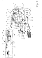
- Fig. 1 shows a known round agricultural baler 1 on the one hand with a constant pressure chamber 2 and on the other hand with a variable pressing chamber 3 in a side view and a sectional view.
- the round baler 1 is used for receiving and pressing to a swath 4 stored on the ground 5 crop 6 to a round bale 7.
- the recording of the stored on the bottom 5 Erntegutschwads 4 via a Erntegutabilityvoriques 8, the crop 6 via a Gutzu Foodö réelle 9 of the pressing chamber 2, 3 supplies.
- the pressing chamber 2, 3 is peripherally limited by pressing means.
- the pressing means are designed as clock-driven press rolls 10, wherein the axes of rotation 11 of the press rolls 10 are parallel to each other and lie on a circular arc.
- the pressing means 10, 13 are designed as counter-clockwise driven over rollers 12 pressing belts 13 which extend parallel to each other at a small distance. They are guided by a plurality of non-driven rollers 14.
- the pressing chamber 2.3 is divided into a front half 15 and a rear half 16, wherein the halves 15, 16 are connected together in an upper bearing 17, so that the rear half 16 of the round baler 1 for ejecting the Bale 7 can be pivoted in a conventional manner.
- a binding device 18 known per se is arranged in front of a pull-in gap 19 extending over the entire width of the press chamber for the twine 20.
- the binding device 18 shown in an enlarged plan view comprises a mounted on a frame 22 and herverfahrbar mounted yarn guide device 23 with Garn Installationsscher not shown.
- the shaft 27 is after extended from and to a control cylinder 29, in this case an electric motor 30, coupled, which is fixed to the frame 22.
- the chain drive 32 is arranged so that it surrounds the yarn guiding device 23 in its back and forth movement via guide elements, not shown.
- the binding device 18 has a separating element (not shown here in detail) for severing the twine after a binding operation has been carried out.
- the desired bale density or bale size is set by the operator via an operating device 35, preferably the operation is carried out by the towing vehicle, not shown here Round baler 1 off.
- bale size sensors are provided on the round baler 1.
- the signals sensed by the bale size sensors are detected by an unspecified control device and compared with the desired bale size. If the actual bale size coincides with the target bale size, the operator of the round baler 1 is given a signal to stop the baler via a known display unit, not shown here on the towing vehicle.
- the controller waits for a short interval to give the operator time to stop forward movement of the round baler 1 and then automatically drives a control device 36 that drives the binding device 18 and then automatically initiates a binding operation to wrap the finished pressed round bale 7 with twine 20 , Alternatively, the binding process can also be triggered manually by the operator of the round baler 1.
- the Bindegarnumwicklungsiere for the binding process according to the bale diameter was chosen in advance, the exact distribution on the bale circulation surface 37, however, are not controlled. So that the binding yarn distribution can be optimized by means of the continuously movable yarn guiding device 23 on the bale circulation surface 37 of the finished round bale 7 at each binding operation according to the desired Bindegarnumwicklungsiere, means are provided according to the invention, which control the twine distribution depending on the almost actual peripheral speed of the bale during the binding process.
- the means of at least one yarn guiding device 23 along the bale peripheral surface 37 leading designed as an electric motor 30, adjusting means 29 and a controlling this controlling device is formed, whereby a continuous adjustment of the yarn guide device 23 is achievable and thus an optimization of the twine distribution can be done.
- the pressing chamber 2, 3 is associated with at least one sensor 14, 39, 40, which is associated with a yarn guiding device 23 controlling controller 36 is in communication, which is supplied to the detected signal.
- the sensor 14, 39, 40 may be formed as a non-driven roller 14, which is in direct contact with the pressing means designed as a press belt 13, so that already in a round baler 7 with variable pressing chamber 3 existing technical means for sensing the bale circulation speed available are.
- the at least one sensor 14, 39 40 can alternatively be embodied as a measuring wheel 39 which is in contact with a finished round bale 7 and is in the form of a gear, for example, and / or as a non-driven roller 40 in contact with the finished round bale 7 that in round balers 1 with a constant pressure chamber 2 in a technically simple manner, the ball peripheral speed of the finished pressed bale detectable and thus for controlling the Garn Equipments worn 23 is available.
- the bale circulation speed of the pressed round bale 7 detected by the at least one sensor 14, 39, 40 is fed to a transmitter 38 as a signal, which converts this signal into a calculated variable.
- the calculated size defines itself as the almost exact bale speed of the finished pressed round bale 7 during the binding process.
- the evaluation 38 determines the appropriate exact feed rate for the process of Garn Operationss worn 23 along the ball peripheral surface 37 and passes a feed rate representing this signal to the yarn guide device 23 controlling control device 36th
- the binding device 18 thereby conveys the twine 20 by means of the yarn guiding device 23 via guide elements, not shown, between two adjacent rollers 12 or pressing belts 13, so that the twine 20 is guided onto the ball circulation surface 37 of the finished pressed round bale 7. Due to the rotational speed of the round bale 7, as well as by the rotation of the pressing means 12, 13, the twine 20 is taken.
- the yarn guiding device 23 remains in its starting position in order to apply a predefined number of end turns on the rotating surface 37. Given a predetermined time, the yarn guide device 23 is then moved at the determined feed rate to the opposite end to apply the desired number of circular turns on the bale circulation surface 37.
- the Gam operations engaged 23 pauses again to apply the desired number of Endwindungen. It is also conceivable that the Gam operations engaged 23 is made of several parts and during the binding process each from the center to the endings of the bale circulation surface 37 back and forth. In addition, the number of existing Garn Unitsscher 31 is variable.
- the binder yarn distribution on the bale circulation surface 37 is controlled depending on the bale circulation speed.
- the evaluation electronics 38 continuously calculates a feed rate adapted to the detected signals for the process of Garn operations driven 23 along the Balfenumlauf construction 37, so that advantageously the Almost exact compliance with the pre-defined Windungsabnoi on the bale circulation surface 37 can be achieved.
- At least one sensor 14, 39, 40 continuously senses the peripheral peripheral speed of the finished pressed round bale 7 when the bale target diameter defined in advance by the operator is reached From the values of the bale speed, the measured bale diameter and the previously desired Bindegarnumwicklungsiere the evaluation 38 then continuously calculates the necessary to achieve the optimum or desired twine distribution feed rate with which the Garn embodiments worn along the bale circulation surface 37 for Applying the circular turns is moved.
- the binding yarn 20 is separated by a known per se separation device not shown here.
- the yarn guiding device 23 remains in the end position until the triggering of the next binding operation, in order to effect the binder yarn distribution on the bale circulation surface 37 from there, alternatively the yarn guiding device 23 can be returned to its starting position.
- the finished wrapped round bale 7 is conveyed out of the press room 2, 3 by the upward pivoting of the rear press half 16 and deposited on the floor 5 behind the round baler 7.
- bale placement Following the bale placement, harvesting continues to form a new round bale wrapped in twine.
Landscapes
- Life Sciences & Earth Sciences (AREA)
- Environmental Sciences (AREA)
- Storage Of Harvested Produce (AREA)
- Basic Packing Technique (AREA)
- Mushroom Cultivation (AREA)
Description
- Die Erfindung bezieht sich auf eine Bindevorrichtung an landwirtschaftlichen Rundballenpressen, nach dem Oberbegriff des Patentanspruchs 1.
- Bereits aus der
DE OS 26 45 762 ist eine Bindevorrichtung für eine Rundballenpresse bekannt, wobei die Führungseinrichtung mittels eines Antriebsmotors stufenlos verfahrbar ist. Die Einführung des Bindegarns zu Beginn des Bindevorgangs erfolgt dabei an einem Ende des Einzugspaltes. Da die Vorschubbewegung der Garnführungseinrichtung durch den Antriebsmotor unabhängig von der tatsächlichen Umlaufgeschwindigkeit des Ballens während des Bindevorgangs ist, kann sich in nachteiliger Weise von Ballenbindung zu Ballenbindung eine nicht homogene Verteilung der vorab definierten Bindegarnumwicklungszahlen ergeben, was letztendlich zu einem höheren Bindegarnverbrauch führen kann. - Es ist ferner aus der
DE OS 26 40 563 eine Bindevorrichtung bekannt, bei der die Bezugsgröße für die Schwenkbewegung der Garnführungseinrichtung die Einzugslänge des Bindematerials ist. Eine derartige Bindevorrichtung erbringt die Einhaltung vorgegebener Windungsabstände unabhängig von Änderungen in der tatsächlichen Umlaufgeschwindigkeit des Rundballens während des Bindevorgangs. Nachteilig daran ist, dass die vorgegebenen Windungsabstände dann nur in Abhängigkeit vom vorher festegelegten Ballendurchmesser erfolgen, ohne Einbeziehung der tatsächlichen Ballendrehzahl bzw. Ballenumlaufgeschwindigkeit des jeweils fertig gepressten Ballens, die wegen Schlupfes des Ballens während jedes Ballenbindevorgangs unterschiedlich ausfallen kann, so dass sich von einem Ballenbindevorgang zum nächsten eine ungenaue Bindegarnverteilung ergeben kann und dadurch eine schlechte Ballenumhüllung entsteht, was zu losen Ballen oder dazu führen kann, dass die vorab bestimmte Bindegarnlänge von vornherein um ein gewisses Maß verlängert wird, um die beschriebenen Nachteile zu vermeiden. - Eine optimierte Bindegarnverteilung auf der Umlauffläche des fertig gepressten Ballens und ein daraus resultierender verminderter Bindegarnverbrauch können letztlich auch mit dieser Bindevorrichtung nicht gewährleistet werden.
-
US-A-4624 179 offenbart eine Rundballenpresse wobei die Bindeeinrichtung gesteuert wird mit Berücksichtigung der Geschwindigkeit der Ballenförmungsmittel. - Es ist daher Aufgabe der Erfindung, die Nachteile des zitierten Standes der Technik zu vermeiden und eine optimale Bindegarnverteilung und damit einen optimalen Bindgarnverbrauch zu gewährleisten.
- Diese Aufgabe wird erfindungsgemäß durch die kennzeichnenden Merkmale des Patentanspruchs 1 gelöst, während gemäß den kennzeichnenden Merkmalen des Patentanspruchs 12 ein die Aufgabe lösendes Verfahren aufgezeigt wird. In den weiteren Patentansprüchen sind Merkmale aufgeführt, die diese Lösungen in vorteilhafter Weise weiterentwickeln.
- Indem Mittel zur Steuerung der Bindegarnverteilung in Abhängigkeit von der Ballenumfangsgeschwindigkeit des fertig gepressten Ballens vorgesehen sind, wird sichergestellt, dass die vorab definierte Bindegarnverteilung, wie auch die Einhaltung der gewünschten Windungsabstände eingehalten werden können, dadurch, dass nun während des Bindevorgangs auftretende Schwankungen in der Ballenumlaufgeschwindigkeit eine Berücksichtigung finden.
- In vorteilhafter Weiterbildung der Erfindung sind die Mittel von zumindest einem die Garnführungseinrichtung entlang des Ballenumfangs führenden Stellmittel und einer diesen ansteuernden Steuereinrichtung gebildet, wodurch vorteilhaft, die Position der Garnführungsvorrichtung genau bestimmbar ist, so dass eine optimale Bindegarnverteilung auf der Umfangsfläche des fertig gepressten Ballens erfolgen kann. Um eine stufenlose Positionierung der Garnführungsvorrichtung zu erreichen, ist das Stellmittel vorzugsweise als Elektromotor ausgeführt, so dass insbesondere in den Randbereichen der Ballen eine optimale Bindegarnverteilung erreichbar ist.
- Damit eine nahezu exakte die vorab festgelegten Windungsabstände berücksichtigende Bindegarnverteilung erreicht werden kann, wird die Vorschubgeschwindigkeit der Garnführungsvorrichtung in Abhängigkeit von der Ballenumfangsgeschwindigkeit, dem gemessenen Ballendurchmesser sowie der gewünschten Bindegarnumwicklungszahl ermittelt, so dass die Bindegarnverteilung nicht allein auf angenommene Werte beruht.
- lm einfachsten Fall kann die Ballenumlaufgeschwindigkeit des fertig gepressten Ballens mittels wenigstens eines an sich bekannten Sensors ermittelt und einer Auswerteelektronik als Signal zugeleitet werden, die dieses Signal in eine Rechengröße umsetzt und zur Steuerung der Garnführungseinrichtung nutzbar macht, wobei vorzugsweise die nahezu exakte Ballendrehzahl des fertig gepressten Ballens während des Bindevorgangs die Rechengröße bildet.
- In vorteilhafter Weise ist der wenigstens eine Sensor als eine mit einem Pressmittel in Kontakt stehende nicht angetriebene Walze oder als ein mit dem Ballen in Kontakt stehendes Messrad ausgeführt, so dass einerseits die in einer Rundballenpresse mit variablen Ballenpressraum vorhandenen nicht angetriebenen Walzen, die mit dem als Pressbänder ausgeführten Pressmittel in Kontakt stehen, als Sensor nutzbar sind oder andererseits durch Anordnung eines Messrades im Pressraum mit geringem technischen Aufwand die Ballengeschwindigkeit erfassbar ist.
- Demgegenüber kann der Sensor als eine mit dem fertig gepressten Ballen in Kontakt stehende nicht angetriebene Walze ausgeführt sein, so dass vorteilhaft in Rundballenpressen mit fester Ballenpresskammer auf technisch einfache Weise die tatsächliche Ballenumfangsgeschwindigkeit des fertig gepressten Ballens erfassbar ist.
- Zur Entlastung des Bedieners ist der Rundballenpresse zur Einstellung des gewünschten Ballendurchmessers eine Bedieneinrichtung zugeordnet, die vorzugsweise von der Zugmaschine der Rundballenpresse bedienbar ist.
- Ein besonders vorteilhaftes Verfahren zur Steuerung der Bindegarnverteitung unter Nutzung der Bindevorrichtung sieht vor, dass die Bindegarnverteilung auf der Umfangsfläche des Ballens in Abhängigkeit von dessen Ballenumlaufgeschwindigkeit gesteuert wird, so dass selbst bei auftretendem Schlupf des Ballens während des Bindevorgangs ein die gewünschten Windungsabstände berücksichtigende Bindegarnverteilung erreichbar ist.
- Eine besonders vorteilhafte Weiterbildung des Verfahrens wird dann erreicht, wenn nach Erreichen des vorab definierten Solldurchmessers des Ballens, ein Sensor kontinuierlich die tatsächliche Ballenumfangsgeschwindigkeit des fertig gepressten Ballen ermittelt, eine Auswertelektronik die ermittelten Sensordaten erfasst und in eine Rechengröße, vorzugsweise in die nahezu exakte Ballendrehzahl umsetzt, die Auswerteeinheit kontinuierlich aus der Rechengröße und mindestens den Werten des tatsächlichen Ballendurchmessers und einer vorab definierten Bindegarnumwicklungszahl bzw. der gewünschten Windungsabstände durch einen wählbaren Algorithmus die entsprechende Vorschubgeschwindigkeit der Garnführungseinrichtung errechnet und eine Steuereinrichtung mittels eines Stellzylinders die Garnführungseinrichtung entlang der Ballenumfangsfläche entsprechend der errechneten Vorschubgeschwindigkeit betreibt. Dies hat den Vorteil, dass die Bindegarnverteilung stufenlos der nahezu tatsächlichen Ballenumfangsgeschwindigkeit des fertig gepressten Ballen angepasst werden kann, so dass jeder Rundballen eine Bindung aufweist.
- Weitere vorteilhafte Ausgestaltungen sind Gegenstand weiterer Unteransprüche und werden anhand der nachfolgenden Zeichnung näher erläutert.
- Es zeigt:
- Figur 1:
- eine Rundballenpresse in Seitenansicht und Schnittdarstellung
-
Fig. 1 zeigt eine an sich bekannte landwirtschaftliche Rundballenpresse 1 einerseits mit einer konstanten Presskammer 2 und andererseits mit einer variablen Presskammer 3 in einer Seitenansicht und einer Schnittdarstellung. Die Rundballenpresse 1 dient der Aufnahme und dem Pressen von zu einem als Schwad 4 auf dem Boden 5 abgelegten Erntegut 6 zu einem Rundballen 7. Die Aufnahme des auf dem Boden 5 abgelegten Erntegutschwads 4 erfolgt über eine Erntegutaufnahmevorrichtung 8, die das Erntegut 6 über eine Gutzuführöffnung 9 der Presskammer 2, 3 zuführt. Die Presskammer 2, 3 wird umfangsseitig von Pressmitteln begrenzt. Einerseits sind die Pressmittel als im Uhrzeigersinn angetriebene Presswalzen 10 ausgeführt, wobei die Drehachsen 11 der Presswalzen 10 parallel zueinander verlaufen und auf einem Kreisbogen liegen. Andererseits sind die Pressmittel 10, 13 als entgegen dem Uhrzeigersinn über Walzen 12 angetriebene Pressbänder 13 ausgeführt, die mit geringem Abstand parallel nebeneinander verlaufen. Sie werden durch eine Vielzahl von nicht angetriebenen Walzen 14 geführt. - In an sich bekannter Weise ist die Presskammer 2,3 in eine vordere Hälfte 15 und eine rückwärtige Hälfte 16 unterteilt, wobei die Hälften 15, 16 in einem oberen Lager 17 miteinander verbunden sind, so dass die rückwärtige Hälfte 16 der Rundballenpresse 1 zum Auswerfen des Ballens 7 in herkömmlicher Weise aufgeschwenkt werden kann.
- Im oberen Bereich der vorderen Pressenhälfte 15 ist eine an sich bekannte Bindevorrichtung 18 vor einem sich über die gesamte Breite der Presskammer erstreckenden Einzugsspaltes 19 für das Bindegarn 20 angeordnet. Die Bindevorrichtung 18 in einer vergrößerten Draufsicht dargestellt, umfasst eine auf einen Rahmengestell 22 hin- und herverfahrbar gelagerte Garnführungseinrichtung 23 mit nicht näher dargestellten Garnführungsösen. In einem gewissen Abstand, beispielhaft ca. 100 mm, von den Seitenwänden 24 ist auf dem Rahmengestell 22 je ein Kettenrad 25, 26 freiliegend auf Wellen 27, 28 gelagert. Die Welle 27 ist nach vom verlängert und an einen Stellzylinder 29, vorliegend einen Elektromotor 30, gekuppelt, der am Rahmengestell 22 befestigt ist. Der Kettentrieb 32 ist dabei so angeordnet, dass er über nicht näher dargestellte Führungselemente die Garnführungseinrichtung 23 bei deren Hin- und Zurückbewegung umschließt. Darüber hinaus besitzt die Bindevorrichtung 18 ein hier nicht näher dargestelltes Abtrennorgan zum Durchtrennen des Bindegarns nach Durchführung eines Bindevorgangs.
- Vor dem Start eines Bindevorgangs wird die gewünschte Ballendichte bzw. Ballengröße vom Bediener über eine Bedieneinrichtung 35 eingestellt, vorzugsweise erfolgt dabei die Bedienung vom hier nicht dargestellten Zugfahrzeug der Rundballenpresse 1 aus. Zur Erfassung der Ballengröße sind an sich bekannte und daher nicht näher dargestellte Ballengröße-Sensoren an der Rundballenpresse 1 vorgesehen. Die von den Ballengröße-Sensoren sensierten Signale werden von einer nicht näher beschriebenen Steuereinrichtung erfasst und mit der gewünschten Ballengröße verglichen. Wenn die Ist-Ballengröße mit der Sollballengröße übereinstimmt, wird dem Bediener der Rundballenpresse 1, über eine bekannte hier nicht dargestellte Anzeigeneinheit auf dem Zugfahrzeug ein Signal zum Stoppen der Ballenpresse gegeben. Die Steuereinrichtung wartet über ein kurzes Intervall, um dem Bediener Zeit zum Stoppen der Vorwärtsbewegung der Rundballenpresse 1 zu geben und steuert dann automatisch eine die Bindevorrichtung 18 ansteuernde Steuereinrichtung 36 an und leitet dann automatisch einen Bindevorgang zum Umwickeln des fertig gepressten Rundballens 7 mit Bindegarn 20 ein. Alternativ kann der Bindevorgang auch manuell durch den Bediener der Rundballenpresse 1 ausgelöst werden.
- Bislang konnte zwar die Bindegarnumwicklungszahl für den Bindevorgang entsprechend des Ballendurchmessers vorab gewählt, deren genaue Verteilung auf der Ballenumlauffläche 37 jedoch nicht gesteuert werden. Damit die Bindgarnverteilung mittels der stufenlos verfahrbaren Garnführungseinrichtung 23 auf der Ballenumlauffläche 37 des fertig gepressten Rundballens 7 bei jedem Bindevorgang entsprechend der gewünschten Bindegarnumwicklungszahl optimiert werden kann, sind erfindungsgemäß Mittel vorgesehen, die die Bindegarnverteilung in Abhängigkeit von der nahezu tatsächlichen Ballenumfangsgeschwindigkeit während des Bindevorgangs steuern. Zum Sensieren der nahezu exakten Ballenumfangsgeschwindigkeit sind die Mittel von zumindest einem die Garnführungseinrichtung 23 entlang der Ballenumfangsfläche 37 führenden, als Elektromotor 30 ausgeführten, Stellmittel 29 und einer dieses ansteuernden Steuereinrichtung gebildet, wodurch eine stufenlose Verstellung der Garnführungseinrichtung 23 erreichbar ist und damit eine Optimierung der Bindegarnverteilung erfolgen kann.
- Zur kontinuierlichen Erfassung der Umlaufgeschwindigkeit des fertig gepressten Rundballens 7 während des Bindevorgangs ist der Presskammer 2, 3 wenigstens ein Sensor 14, 39, 40 zugeordnet, der mit einer die Garnführungseinrichtung 23 steuernden Steuereinrichtung 36 in Verbindung steht, welcher das erfasste Signal zugeleitet wird. Beispielsweise kann der Sensor 14, 39, 40 als eine nicht angetriebene Walze 14 ausgebildet sein, die mit dem als Pressband 13 ausgeführten Pressmittel unmittelbar in Kontakt steht, so dass bereits in einer Rundballenpresse 7 mit variabler Presskammer 3 vorhandene technische Mittel zum Sensieren der Ballenumlaufgeschwindigkeit nutzbar sind. Der wenigstens eine Sensor 14, 39 40 kann alternativ als ein mit einem fertig gepressten Rundballen 7 in Kontakt stehendes, beispielhaft als Zahnrad ausgeführtes Messrad 39 und/oder als eine mit dem fertig gepressten Rundballen 7 in Kontakt stehende nicht angetriebene Walze 40 ausgeführt sein, so dass in Rundballenpressen 1 mit konstanter Presskammer 2 auf technisch einfache Weise die Ballenumfangsgeschwindigkeit des fertig gepressten Ballens erfassbar und damit zur Steuerung der Garnführungseinrichtung 23 nutzbar ist.
- Die durch den wenigstens einen Sensor 14, 39, 40 erfasste Ballenumlaufgeschwindigkeit des gepressten Rundballens 7 wird einer Auswerteelektronik 38 als Signal zugeleitet, die dieses Signal in eine Rechengröße, umsetzt. Vorzugsweise definiert sich die Rechengröße als die nahezu exakte Ballendrehzahl des fertig gepressten Rundballens 7 während des Bindevorgangs. Anhand der ermittelten Ballendrehzahl, dem gemessenen Ballendurchmesser und der gewünschten Bindegamumwicklungszahl ermittelt die Auswerteelektronik 38 die entsprechende exakte Vorschubgeschwindigkeit für das Verfahren der Garnführungseinrichtung 23 entlang der Ballenumfangsfläche 37 und leitet ein diese Vorschubgeschwindigkeit repräsentierendes Signal an die die Garnführungseinrichtung 23 steuernde Steuereinrichtung 36.
- Die Bindevorrichtung 18 fördert dabei das Bindegarn 20 mittels der Garnführungseinrichtung 23 über nicht näher dargestellte Leitelemente zwischen zwei benachbarte Walzen 12 bzw. Pressbänder 13 hindurch, so dass das Bindegarn 20 auf die Ballenumlauffläche 37 des fertig gepressten Rundballens 7 geführt wird. Durch die Umlaufgeschwindigkeit des Rundballens 7, wie auch durch die Rotation der Pressmittel 12, 13 wird das Bindegarn 20 mitgenommen. Zunächst verharrt die Garnführungseinrichtung 23 in ihrer Ausgangsposition, um eine vorab definierte Anzahl an Endwindungen auf der Umlauffläche 37 aufzubringen. Unter Vorgabe einer festgelegten Zeit wird die Garnführungseinrichtung 23 dann mit der ermittelten Vorschubgeschwindigkeit zur gegenüberliegenden Endung verfahren, um die gewünschte Anzahl von kreisförmigen Windungen auf der Ballenumlauffläche 37 aufzubringen. An der gegenüberliegenden Endung der Ballenumlauffläche 37 verharrt die Gamführungseinrichtung 23 erneut, um die gewünschte Anzahl von Endwindungen aufzubringen. Denkbar ist auch, dass die Gamführungseinrichtung 23 mehrteilig ausgeführt ist und während des Bindevorgangs jeweils von der Mitte aus zu den Endungen der Ballenumlauffläche 37 hin- und herverfahren werden. Zudem ist die Anzahl der vorhandenen Garnführungsösen 31 variabel.
- Gemäß dem erfindungsgemäßen Verfahren zur Steuerung der Bindegarnverteilung wird die Bindegarnverteilung auf der Ballenumlauffläche 37 in Abhängigkeit von der Ballenumlaufgeschwindigkeit gesteuert. Sensiert der wenigstens eine Sensor 14, 39, 40 während des Bindevorgangs beispielsweise durch Schlupf des Rundballens 7 resultierende Schwankungen der Ballenumfaufgeschwindigkeit, errechnet die Auswertelektronik 38 kontinuierlich eine den erfassten Signalen angepasste Vorschubgeschwindigkeit für das Verfahren der Garnführungseinrichtung 23 entlang der Balfenumlauffläche 37, so dass vorteilhaft die nahezu exakte Einhaltung der vorab definierten Windungsabstände auf der Ballenumlauffläche 37 erreicht werden kann.
- Bei einer vorteilhaften Ausführung des Verfahrens zur Steuerung der Bindegarnverteilung auf der Ballenumlauffläche sensiert mit Erreichen des vorab durch den Bediener definierten Ballen-Solldurchmessers wenigstens ein Sensor 14, 39, 40 kontinuierlich die Ballenumfangsgeschwindigkeit des fertig gepressten Rundballens 7. Eine damit verbundene Auswertelektronik 38 erfasst die ermittelten Signale und errechnet daraus die Ballendrehzahl des Rundballens 7. Aus den Werten der Ballendrehzahl, des gemessenen Ballendurchmessers sowie der vorab gewünschten Bindegarnumwicklungszahl berechnet die Auswerteelektronik 38 dann kontinuierlich die zur Erreichung der optimalen bzw. gewünschten Bindegarnverteilung notwendige Vorschubgeschwindigkeit mit welcher die Garnführungseinrichtung entlang der Ballenumlauffläche 37 zum Aufbringen der kreisförmigen Windungen verfahren wird. Bei auftretenden Schwankungen in der Ballenumlaufigeschwindigkeit erhält die die Garnführungseinrichtung steuernde Steuereinrichtung 36 entsprechende Signale, die Garnführungseinrichtung schneller bzw. langsamer zu verfahren, um die Schwankungen auszugleichen, so dass jeder gepresste Rundballen 7 eine optimale Bindung aufweist und ein optimaler Bindegarnverbrauch gewährleistet ist.
- Nach Vollendung des Bindevorgangs wird das Bindgarn 20 durch eine an sich bekannte hier nicht näher dargestellte Abtrennvorrichtung abgetrennt.
- Die Garnführungseinrichtung 23 verharrt in der Endstellung bis zum Auslösen des nächsten Bindevorgangs, um von dort aus die Bindegarnverteilung auf der Ballenumlauffläche 37 zu bewirken, alternativ kann die Garnführungseinrichtung 23 in ihre Ausgangstellung zurückverfahren werden.
- Danach wird der fertig umwickelte Rundballen 7 durch das aufwärts Verschwenken der rückwärtigen Pressenhälfte 16 aus dem Pressraum 2, 3 heraus gefördert und auf dem Boden 5 hinter der Rundballenpresse 7 abgelegt.
- Im Anschluss an die Ballenablage wird die Erntefahrt fortgesetzt zum Bilden eines neuen mit Bindegarn umhüllten Rundballens.
- Es liegt im Rahmen des Könnens eines Fachmanns, die beschriebene Erfindung in nicht dargestellter Weise abzuwandeln oder in anderen als den dargestellten Anwendungsfällen einzusetzen, um die beschriebenen Effekte zu erzielen, ohne dabei den Rahmen der Erfindung zu verlassen.
-
- 1
- landwirtschaftliche Rundballenpresse
- 2
- konstante Presskammer
- 3
- variable Presskammer
- 4
- Schwad
- 5
- Boden
- 6
- Erntegut
- 7
- Rundballen
- 8
- Erntegutzuführvorrichtung
- 9
- Gutzuführöffnung
- 10
- angetriebene Presswalzen
- 11
- Drehachsen
- 12
- angetriebene Walzen
- 13
- Pressband
- 14
- nicht angetriebene Walzen
- 15
- vordere Hälfte
- 16
- rückwärtige Hälfte
- 17
- Lager
- 18
- Bindevorrichtung
- 19
- Einzugsspalt
- 20
- Bindegarn
- 22
- Rahmengestell
- 23
- Gamführungseinrichtung
- 24
- Seitenwände
- 25
- Kettenrad
- 26
- Kettenrad
- 27
- Welle
- 28
- Welle
- 29
- Stellmittel
- 30
- Elektromotor
- 32
- Kettentrieb
- 35
- Bedieneinrichtung
- 36
- Steuereinrichtung
- 37
- Ballenumfauffläche
- 38
- Auswerteelektronik
- 39
- Messrad
- 40
- nicht angetriebene Walze
Claims (13)
- Bindevorrichtung (18) an einer Rundballenpresse (7) mit einer Presskammer (2,3) zur Aufnahme, Bündelung und Abgabe von landwirtschaftlichen Erntegut (6), welche mittels eines Stellzylinders (29) stufenlos verfahrbar und über einen sich über die gesamte Breite der Presskammer (2,3) erstreckenden Einzugsspalts (19) angeordnet ist, bestehend aus einer auf einer Schiebeführung vor und entlang dem Einzugsspalt (19) gegenläufig verschiebbaren Garnführungseinrichtung (23) und einer ortsfest vor dem Einzugsspalt angeordneten Schneidvorrichtung zum Abschneiden des Bindegarns (20) nach Abschluss des Bindevorgangs,
dadurch gekennzeichnet,
dass Mittel zur Steuerung der Bindegarnverteitung in Abhängigkeit von der Ballenumfangsgeschwindigkeit während des Bindevorgangs vorgesehen sind. - Bindevorrichtung (18) nach Anspruch 1,
dadurch gekennzeichnet,
dass die Mittel von zumindest einem die Garnführungseinrichtung (23) entlang der Ballenumfangsfläche (37) führenden Stellmittel (29) und einer dieses ansteuernde Steuereinrichtung (36) gebildet sind. - Bindevorrichtung (18) nach einem der vorhergehenden Ansprüche,
dadurch gekennzeichnet,
dass das Stellmittel (29) zur Führung der Garnführungseinrichtung (23) entlang der Ballenumfangsfläche (37) als Elektromotor (30) ausgeführt ist. - Bindevorrichtung (18) nach einem der vorhergehenden Ansprüche,
dadurch gekennzeichnet,
dass das Verfahren der Garnführungseinrichtung (23) in Abhängigkeit von der Ballenumfangsgeschwindigkeit, dem gemessenem Ballendurchmesser sowie der gewünschten Bindergarnumwicklungszahl stufenlos regelbar ist. - Bindevorrichtung (18) nach einem der vorhergehenden Ansprüche,
dadurch gekennzeichnet,
dass die Ballenumfangsgeschwindigkeit des fertig gepressten Rundballens (7) durch zumindest einen Sensor erfasst und einer Auswerteelektronik (38) als Signal zugeführt wird und dieses Signal in eine Rechengröße umsetzbar ist, welche zur Steuerung der Garnführungseinrichtung (23) nutzbar ist. - Bindevorrichtung (18) nach Anspruch 5,
dadurch gekennzeichnet,
dass die Rechengröße die nahezu tatsächliche Ballendrehzahl des fertig gepressten Rundballens (7) während des Bindevorgangs ist. - Bindevorrichtung (18) nach einem der vorhergehenden Ansprüche 5 oder 6,
dadurch gekennzeichnet,
dass der Sensor als eine mit einem Pressmittel in Kontakt stehende nicht angetriebene Walze (14) und/oder als ein mit dem fertig gepressten Rundballen (7) in Kontakt stehendes Messrad (39) ausgeführt ist. - Bindevorrichtung (18) nach einem der vorhergehenden Ansprüche 5 bis 7,
dadurch gekennzeichnet,
dass der Sensor als eine mit dem fertig gepressten Rundballen (7) in Kontakt stehende nicht angetriebene Walze (40) ausgeführt ist. - Bindevorrichtung (18) nach einem der vorhergehenden Ansprüche,
dadurch gekennzeichnet,
dass die Rundballenpresse (1) eine Bedieneinrichtung (35) zur Einstellung des gewünschten Ballendurchmessers umfasst. - Bindevorrichtung (18) nach Anspruch 9,
dadurch gekennzeichnet,
dass die Bedieneinrichtung (35) vom Zugfahrzeug der Rundballenpresse (1) aus bedienbar ist. - Bindevorrichtung (18) nach einem der vorhergehenden Ansprüche,
dadurch gekennzeichnet,
dass die Rundballenpresse (1) mit fester oder variabler Presskammer ausgeführt (2, 3) ist. - Verfahren zur Steuerung der Bindegarnverteilung mittels einer Bindevorrichtung (18) an einer Rundballenpresse (7) mit einer Presskammer (2,3) zur Aufnahme, Bündelung und Abgabe von landwirtschaftlichen Erntegut (6), welche mittels eines Stellzylinders (29) stufenlos verfahrbar und über einen sich über die gesamte Breite der Presskammer (2,3) erstreckenden Einzugsspalts (19) angeordnet ist, bestehend aus einer auf einer Schiebeführung vor und entlang dem Einzugsspalt (19) gegenläufig verschiebbaren Garnführungseinrichtung (23) und einer ortsfest vor dem Einzugsspalt angeordneten Schneidvorrichtung zum Abschneiden des Bindegarns (20) nach Abschluss des Bindevorgangs,
dadurch gekennzeichnet,
dass die Bindegarnverteilung auf der Ballenumfangsfläche (37) des Rundballens in Abhängigkeit von der Ballenumfangsgeschwindigkeit des fertig gepressten Ballens gesteuert wird. - Verfahren nach Anspruch 12,
dadurch gekennzeichnet,
dass- nach Erreichen eines vorab definierten Solldurchmessers des Rundballens (7),- der wenigstens eine Sensor kontinuierlich die Ballenumfangsgeschwindigkeit des fertig gepressten Rundballens (7) ermittelt,- eine Auswertelektronik (38) die ermittelten Sensorsignale erfasst, und in eine Rechengröße umsetzt,- die Auswertelektronik (38) kontinuierlich aus der Rechengröße, dem Ballendurchmesser des fertig gepressten Rundballens (7), der vorab definierten Bindegarnumwicklungszahl bzw. des Windungsabstandes durch einen wählbaren Algorithmus die Vorschubgeschwindigkeit der Garnführungseinrichtung errechnet, und- eine Steuereinrichtung (36) mittels des Stellmittels (29) die Garnführungseinrichtung (23) entlang der Ballenumfangsfläche entsprechend der errechneten Vorschubgeschwindigkeit steuert.
Applications Claiming Priority (1)
| Application Number | Priority Date | Filing Date | Title |
|---|---|---|---|
| DE102006033076A DE102006033076A1 (de) | 2006-07-14 | 2006-07-14 | Bindevorrichtung an landwirtschaftlichen Rundballenpressen |
Publications (3)
| Publication Number | Publication Date |
|---|---|
| EP1878333A2 EP1878333A2 (de) | 2008-01-16 |
| EP1878333A3 EP1878333A3 (de) | 2008-01-23 |
| EP1878333B1 true EP1878333B1 (de) | 2010-08-25 |
Family
ID=38596748
Family Applications (1)
| Application Number | Title | Priority Date | Filing Date |
|---|---|---|---|
| EP07108150A Not-in-force EP1878333B1 (de) | 2006-07-14 | 2007-05-14 | Bindevorrichtung an landwirtschaftliche Rundballenpressen |
Country Status (3)
| Country | Link |
|---|---|
| EP (1) | EP1878333B1 (de) |
| AT (1) | ATE478553T1 (de) |
| DE (2) | DE102006033076A1 (de) |
Families Citing this family (3)
| Publication number | Priority date | Publication date | Assignee | Title |
|---|---|---|---|---|
| CN102133935B (zh) * | 2011-01-04 | 2012-07-25 | 中国农业大学 | 一种对数螺线式圆捆成形装置及方法 |
| US11406063B2 (en) * | 2019-09-11 | 2022-08-09 | Deere & Company | Baler with a moveable roller |
| CN120024541B (zh) * | 2025-04-17 | 2025-07-29 | 西安交通工程学院 | 一种金属线材自动捆扎过程监控方法、系统及设备 |
Family Cites Families (4)
| Publication number | Priority date | Publication date | Assignee | Title |
|---|---|---|---|---|
| DE2640563C3 (de) | 1976-09-09 | 1980-01-10 | Gebr. Claas Maschinenfabrik Gmbh, 4834 Harsewinkel | Bindevorrichtung an Rundballenpressen |
| DE2645762C3 (de) | 1976-10-09 | 1982-07-22 | Gebrüder Welger GmbH & Co KG, 3340 Wolfenbüttel | Vorrichtung zum Umschnüren eines Rollballens aus landwirtschaftlichem Halmgut |
| FR2541561B1 (fr) * | 1983-02-28 | 1986-05-09 | Renault | Dispositif de commande automatique de liage dans une presse a fourrage |
| US5388504A (en) * | 1993-08-23 | 1995-02-14 | Agco Corporation | Twine wrap control for round baler |
-
2006
- 2006-07-14 DE DE102006033076A patent/DE102006033076A1/de not_active Withdrawn
-
2007
- 2007-05-14 AT AT07108150T patent/ATE478553T1/de active
- 2007-05-14 EP EP07108150A patent/EP1878333B1/de not_active Not-in-force
- 2007-05-14 DE DE502007004838T patent/DE502007004838D1/de active Active
Also Published As
| Publication number | Publication date |
|---|---|
| EP1878333A2 (de) | 2008-01-16 |
| EP1878333A3 (de) | 2008-01-23 |
| DE502007004838D1 (de) | 2010-10-07 |
| DE102006033076A1 (de) | 2008-01-24 |
| ATE478553T1 (de) | 2010-09-15 |
Similar Documents
| Publication | Publication Date | Title |
|---|---|---|
| EP1461995B1 (de) | Vorrichtung zum Umhüllen eines Ballens mit einer Hüllbahn, Ballenpresse und Sensor | |
| EP2484197A1 (de) | Rundballenpresse mit seitlichen Führungen für den Pressriemen | |
| EP3298881A1 (de) | Ballenpresse | |
| EP1064839A1 (de) | Vorrichtung zum Sichern eines losen Garnendes auf einem Rundballen | |
| EP3320768B1 (de) | Kombination eines landwirtschaftlichen zugfahrzeugs mit einer grossballenpresse und verfahren zum betreiben einer solchen kombination | |
| DE2645762A1 (de) | Vorrichtung zum umschnueren eines rollballens aus landwirtschaftlichem halmgut | |
| EP3590325A1 (de) | Rundballenpresse und erkennungsverfahren | |
| EP0535532A2 (de) | Verfahren zum Binden eines Ballens und Vorrichtung hierfür | |
| EP1878333A2 (de) | Bindevorrichtung an landwirtschaftliche Rundballenpressen | |
| EP3106024B1 (de) | Rundballenpresse mit mitteln zur führung eines pressriemens | |
| EP3106018B1 (de) | Rundballenpresse mit mitteln zum umwickeln eines ballens | |
| EP1454521B1 (de) | Vorrichtung zum Umhüllen eines Ballens mit einer Hüllbahn und Ballenpresse | |
| EP1525787B1 (de) | Verfahren und Vorrichtung zur Motordrehzahleinstellung an einer landwirtschaftlichen Arbeitsmaschine | |
| EP3106019B1 (de) | Rundballenpresse und zuführwalze für wickelmaterial | |
| DE19705582B4 (de) | Rundballenpresse | |
| EP3123856B1 (de) | Press-wickelkombination zum pressen und umhüllen von rundballen | |
| EP3593623B1 (de) | Erntemaschine mit einer erntegutaufnahmevorrichtung | |
| EP3300585B1 (de) | Rundballenpresse zum aufnehmen und pressen von landwirtschaftlichem erntegut | |
| EP4309491B1 (de) | Rundballenpresse | |
| EP4186350B1 (de) | Verfahren zum betreiben einer rundballenpresse | |
| EP0815719B1 (de) | Rundballenpresse | |
| DE4030091C1 (en) | Mfr. of pressed strands of loose material - involves chambers with rollers and binding device with carrier plate | |
| EP3420806B1 (de) | Umhüllungseinrichtung zur umhüllung eines ballens mit einem hüllmaterial, ballenpresse und verfahren | |
| DE102016011633A1 (de) | Maschine zum Aufnehmen und Pressen von landwirtschaftlichem Erntegut | |
| EP3241426A1 (de) | Erntemaschine mit einer erntegutaufnahmevorrichtung |
Legal Events
| Date | Code | Title | Description |
|---|---|---|---|
| PUAI | Public reference made under article 153(3) epc to a published international application that has entered the european phase |
Free format text: ORIGINAL CODE: 0009012 |
|
| PUAL | Search report despatched |
Free format text: ORIGINAL CODE: 0009013 |
|
| AK | Designated contracting states |
Kind code of ref document: A2 Designated state(s): AT BE BG CH CY CZ DE DK EE ES FI FR GB GR HU IE IS IT LI LT LU LV MC MT NL PL PT RO SE SI SK TR |
|
| AX | Request for extension of the european patent |
Extension state: AL BA HR MK YU |
|
| AK | Designated contracting states |
Kind code of ref document: A3 Designated state(s): AT BE BG CH CY CZ DE DK EE ES FI FR GB GR HU IE IS IT LI LT LU LV MC MT NL PL PT RO SE SI SK TR |
|
| AX | Request for extension of the european patent |
Extension state: AL BA HR MK YU |
|
| 17P | Request for examination filed |
Effective date: 20080723 |
|
| 17Q | First examination report despatched |
Effective date: 20080825 |
|
| AKX | Designation fees paid |
Designated state(s): AT BE BG CH CY CZ DE DK EE ES FI FR GB GR HU IE IS IT LI LT LU LV MC MT NL PL PT RO SE SI SK TR |
|
| GRAP | Despatch of communication of intention to grant a patent |
Free format text: ORIGINAL CODE: EPIDOSNIGR1 |
|
| GRAS | Grant fee paid |
Free format text: ORIGINAL CODE: EPIDOSNIGR3 |
|
| GRAA | (expected) grant |
Free format text: ORIGINAL CODE: 0009210 |
|
| AK | Designated contracting states |
Kind code of ref document: B1 Designated state(s): AT BE BG CH CY CZ DE DK EE ES FI FR GB GR HU IE IS IT LI LT LU LV MC MT NL PL PT RO SE SI SK TR |
|
| REG | Reference to a national code |
Ref country code: GB Ref legal event code: FG4D Free format text: NOT ENGLISH |
|
| REG | Reference to a national code |
Ref country code: CH Ref legal event code: EP |
|
| REG | Reference to a national code |
Ref country code: IE Ref legal event code: FG4D Free format text: LANGUAGE OF EP DOCUMENT: GERMAN |
|
| REF | Corresponds to: |
Ref document number: 502007004838 Country of ref document: DE Date of ref document: 20101007 Kind code of ref document: P |
|
| REG | Reference to a national code |
Ref country code: NL Ref legal event code: VDEP Effective date: 20100825 |
|
| LTIE | Lt: invalidation of european patent or patent extension |
Effective date: 20100825 |
|
| PG25 | Lapsed in a contracting state [announced via postgrant information from national office to epo] |
Ref country code: FI Free format text: LAPSE BECAUSE OF FAILURE TO SUBMIT A TRANSLATION OF THE DESCRIPTION OR TO PAY THE FEE WITHIN THE PRESCRIBED TIME-LIMIT Effective date: 20100825 Ref country code: LT Free format text: LAPSE BECAUSE OF FAILURE TO SUBMIT A TRANSLATION OF THE DESCRIPTION OR TO PAY THE FEE WITHIN THE PRESCRIBED TIME-LIMIT Effective date: 20100825 |
|
| PG25 | Lapsed in a contracting state [announced via postgrant information from national office to epo] |
Ref country code: BG Free format text: LAPSE BECAUSE OF FAILURE TO SUBMIT A TRANSLATION OF THE DESCRIPTION OR TO PAY THE FEE WITHIN THE PRESCRIBED TIME-LIMIT Effective date: 20101125 Ref country code: CY Free format text: LAPSE BECAUSE OF FAILURE TO SUBMIT A TRANSLATION OF THE DESCRIPTION OR TO PAY THE FEE WITHIN THE PRESCRIBED TIME-LIMIT Effective date: 20100825 Ref country code: PL Free format text: LAPSE BECAUSE OF FAILURE TO SUBMIT A TRANSLATION OF THE DESCRIPTION OR TO PAY THE FEE WITHIN THE PRESCRIBED TIME-LIMIT Effective date: 20100825 Ref country code: IS Free format text: LAPSE BECAUSE OF FAILURE TO SUBMIT A TRANSLATION OF THE DESCRIPTION OR TO PAY THE FEE WITHIN THE PRESCRIBED TIME-LIMIT Effective date: 20101225 Ref country code: SI Free format text: LAPSE BECAUSE OF FAILURE TO SUBMIT A TRANSLATION OF THE DESCRIPTION OR TO PAY THE FEE WITHIN THE PRESCRIBED TIME-LIMIT Effective date: 20100825 Ref country code: PT Free format text: LAPSE BECAUSE OF FAILURE TO SUBMIT A TRANSLATION OF THE DESCRIPTION OR TO PAY THE FEE WITHIN THE PRESCRIBED TIME-LIMIT Effective date: 20101227 |
|
| REG | Reference to a national code |
Ref country code: IE Ref legal event code: FD4D |
|
| PG25 | Lapsed in a contracting state [announced via postgrant information from national office to epo] |
Ref country code: SE Free format text: LAPSE BECAUSE OF FAILURE TO SUBMIT A TRANSLATION OF THE DESCRIPTION OR TO PAY THE FEE WITHIN THE PRESCRIBED TIME-LIMIT Effective date: 20100825 Ref country code: LV Free format text: LAPSE BECAUSE OF FAILURE TO SUBMIT A TRANSLATION OF THE DESCRIPTION OR TO PAY THE FEE WITHIN THE PRESCRIBED TIME-LIMIT Effective date: 20100825 Ref country code: NL Free format text: LAPSE BECAUSE OF FAILURE TO SUBMIT A TRANSLATION OF THE DESCRIPTION OR TO PAY THE FEE WITHIN THE PRESCRIBED TIME-LIMIT Effective date: 20100825 Ref country code: GR Free format text: LAPSE BECAUSE OF FAILURE TO SUBMIT A TRANSLATION OF THE DESCRIPTION OR TO PAY THE FEE WITHIN THE PRESCRIBED TIME-LIMIT Effective date: 20101126 |
|
| PG25 | Lapsed in a contracting state [announced via postgrant information from national office to epo] |
Ref country code: IE Free format text: LAPSE BECAUSE OF FAILURE TO SUBMIT A TRANSLATION OF THE DESCRIPTION OR TO PAY THE FEE WITHIN THE PRESCRIBED TIME-LIMIT Effective date: 20100825 Ref country code: DK Free format text: LAPSE BECAUSE OF FAILURE TO SUBMIT A TRANSLATION OF THE DESCRIPTION OR TO PAY THE FEE WITHIN THE PRESCRIBED TIME-LIMIT Effective date: 20100825 |
|
| PG25 | Lapsed in a contracting state [announced via postgrant information from national office to epo] |
Ref country code: EE Free format text: LAPSE BECAUSE OF FAILURE TO SUBMIT A TRANSLATION OF THE DESCRIPTION OR TO PAY THE FEE WITHIN THE PRESCRIBED TIME-LIMIT Effective date: 20100825 Ref country code: CZ Free format text: LAPSE BECAUSE OF FAILURE TO SUBMIT A TRANSLATION OF THE DESCRIPTION OR TO PAY THE FEE WITHIN THE PRESCRIBED TIME-LIMIT Effective date: 20100825 Ref country code: IT Free format text: LAPSE BECAUSE OF FAILURE TO SUBMIT A TRANSLATION OF THE DESCRIPTION OR TO PAY THE FEE WITHIN THE PRESCRIBED TIME-LIMIT Effective date: 20100825 Ref country code: SK Free format text: LAPSE BECAUSE OF FAILURE TO SUBMIT A TRANSLATION OF THE DESCRIPTION OR TO PAY THE FEE WITHIN THE PRESCRIBED TIME-LIMIT Effective date: 20100825 Ref country code: RO Free format text: LAPSE BECAUSE OF FAILURE TO SUBMIT A TRANSLATION OF THE DESCRIPTION OR TO PAY THE FEE WITHIN THE PRESCRIBED TIME-LIMIT Effective date: 20100825 |
|
| PG25 | Lapsed in a contracting state [announced via postgrant information from national office to epo] |
Ref country code: ES Free format text: LAPSE BECAUSE OF FAILURE TO SUBMIT A TRANSLATION OF THE DESCRIPTION OR TO PAY THE FEE WITHIN THE PRESCRIBED TIME-LIMIT Effective date: 20101206 |
|
| PLBE | No opposition filed within time limit |
Free format text: ORIGINAL CODE: 0009261 |
|
| STAA | Information on the status of an ep patent application or granted ep patent |
Free format text: STATUS: NO OPPOSITION FILED WITHIN TIME LIMIT |
|
| 26N | No opposition filed |
Effective date: 20110526 |
|
| REG | Reference to a national code |
Ref country code: DE Ref legal event code: R097 Ref document number: 502007004838 Country of ref document: DE Effective date: 20110526 |
|
| PG25 | Lapsed in a contracting state [announced via postgrant information from national office to epo] |
Ref country code: MT Free format text: LAPSE BECAUSE OF FAILURE TO SUBMIT A TRANSLATION OF THE DESCRIPTION OR TO PAY THE FEE WITHIN THE PRESCRIBED TIME-LIMIT Effective date: 20100825 Ref country code: MC Free format text: LAPSE BECAUSE OF NON-PAYMENT OF DUE FEES Effective date: 20110531 |
|
| REG | Reference to a national code |
Ref country code: CH Ref legal event code: PL |
|
| GBPC | Gb: european patent ceased through non-payment of renewal fee |
Effective date: 20110514 |
|
| PG25 | Lapsed in a contracting state [announced via postgrant information from national office to epo] |
Ref country code: LI Free format text: LAPSE BECAUSE OF NON-PAYMENT OF DUE FEES Effective date: 20110531 Ref country code: CH Free format text: LAPSE BECAUSE OF NON-PAYMENT OF DUE FEES Effective date: 20110531 |
|
| PG25 | Lapsed in a contracting state [announced via postgrant information from national office to epo] |
Ref country code: GB Free format text: LAPSE BECAUSE OF NON-PAYMENT OF DUE FEES Effective date: 20110514 |
|
| PG25 | Lapsed in a contracting state [announced via postgrant information from national office to epo] |
Ref country code: LU Free format text: LAPSE BECAUSE OF NON-PAYMENT OF DUE FEES Effective date: 20110514 |
|
| REG | Reference to a national code |
Ref country code: AT Ref legal event code: MM01 Ref document number: 478553 Country of ref document: AT Kind code of ref document: T Effective date: 20120514 |
|
| PG25 | Lapsed in a contracting state [announced via postgrant information from national office to epo] |
Ref country code: AT Free format text: LAPSE BECAUSE OF NON-PAYMENT OF DUE FEES Effective date: 20120514 |
|
| PG25 | Lapsed in a contracting state [announced via postgrant information from national office to epo] |
Ref country code: TR Free format text: LAPSE BECAUSE OF FAILURE TO SUBMIT A TRANSLATION OF THE DESCRIPTION OR TO PAY THE FEE WITHIN THE PRESCRIBED TIME-LIMIT Effective date: 20100825 |
|
| PG25 | Lapsed in a contracting state [announced via postgrant information from national office to epo] |
Ref country code: HU Free format text: LAPSE BECAUSE OF FAILURE TO SUBMIT A TRANSLATION OF THE DESCRIPTION OR TO PAY THE FEE WITHIN THE PRESCRIBED TIME-LIMIT Effective date: 20100825 |
|
| REG | Reference to a national code |
Ref country code: FR Ref legal event code: PLFP Year of fee payment: 10 |
|
| REG | Reference to a national code |
Ref country code: FR Ref legal event code: PLFP Year of fee payment: 11 |
|
| REG | Reference to a national code |
Ref country code: FR Ref legal event code: PLFP Year of fee payment: 12 |
|
| PGFP | Annual fee paid to national office [announced via postgrant information from national office to epo] |
Ref country code: FR Payment date: 20200522 Year of fee payment: 14 |
|
| PG25 | Lapsed in a contracting state [announced via postgrant information from national office to epo] |
Ref country code: FR Free format text: LAPSE BECAUSE OF NON-PAYMENT OF DUE FEES Effective date: 20210531 |
|
| REG | Reference to a national code |
Ref country code: DE Ref legal event code: R084 Ref document number: 502007004838 Country of ref document: DE |
|
| P01 | Opt-out of the competence of the unified patent court (upc) registered |
Effective date: 20230515 |
|
| REG | Reference to a national code |
Ref country code: DE Ref legal event code: R082 Ref document number: 502007004838 Country of ref document: DE |
|
| PGFP | Annual fee paid to national office [announced via postgrant information from national office to epo] |
Ref country code: DE Payment date: 20240521 Year of fee payment: 18 |
|
| PGFP | Annual fee paid to national office [announced via postgrant information from national office to epo] |
Ref country code: BE Payment date: 20240521 Year of fee payment: 18 |
|
| REG | Reference to a national code |
Ref country code: DE Ref legal event code: R119 Ref document number: 502007004838 Country of ref document: DE |
|
| REG | Reference to a national code |
Ref country code: BE Ref legal event code: MM Effective date: 20250531 |
|
| PG25 | Lapsed in a contracting state [announced via postgrant information from national office to epo] |
Ref country code: DE Free format text: LAPSE BECAUSE OF NON-PAYMENT OF DUE FEES Effective date: 20251202 |
|
| PG25 | Lapsed in a contracting state [announced via postgrant information from national office to epo] |
Ref country code: BE Free format text: LAPSE BECAUSE OF NON-PAYMENT OF DUE FEES Effective date: 20250531 |