EP1877144B1 - Respirator mask with corrective lens frame assembly - Google Patents
Respirator mask with corrective lens frame assembly Download PDFInfo
- Publication number
- EP1877144B1 EP1877144B1 EP06836063A EP06836063A EP1877144B1 EP 1877144 B1 EP1877144 B1 EP 1877144B1 EP 06836063 A EP06836063 A EP 06836063A EP 06836063 A EP06836063 A EP 06836063A EP 1877144 B1 EP1877144 B1 EP 1877144B1
- Authority
- EP
- European Patent Office
- Prior art keywords
- support frame
- corrective lens
- frame
- respirator mask
- bridge
- Prior art date
- Legal status (The legal status is an assumption and is not a legal conclusion. Google has not performed a legal analysis and makes no representation as to the accuracy of the status listed.)
- Expired - Lifetime
Links
Images




Classifications
-
- A—HUMAN NECESSITIES
- A62—LIFE-SAVING; FIRE-FIGHTING
- A62B—DEVICES, APPARATUS OR METHODS FOR LIFE-SAVING
- A62B18/00—Breathing masks or helmets, e.g. affording protection against chemical agents or for use at high altitudes or incorporating a pump or compressor for reducing the inhalation effort
- A62B18/08—Component parts for gas-masks or gas-helmets, e.g. windows, straps, speech transmitters, signal-devices
-
- A—HUMAN NECESSITIES
- A62—LIFE-SAVING; FIRE-FIGHTING
- A62B—DEVICES, APPARATUS OR METHODS FOR LIFE-SAVING
- A62B18/00—Breathing masks or helmets, e.g. affording protection against chemical agents or for use at high altitudes or incorporating a pump or compressor for reducing the inhalation effort
- A62B18/02—Masks
-
- A—HUMAN NECESSITIES
- A62—LIFE-SAVING; FIRE-FIGHTING
- A62B—DEVICES, APPARATUS OR METHODS FOR LIFE-SAVING
- A62B18/00—Breathing masks or helmets, e.g. affording protection against chemical agents or for use at high altitudes or incorporating a pump or compressor for reducing the inhalation effort
- A62B18/08—Component parts for gas-masks or gas-helmets, e.g. windows, straps, speech transmitters, signal-devices
- A62B18/082—Assembling eyepieces, lenses or vision-correction means in or on gas-masks
-
- Y—GENERAL TAGGING OF NEW TECHNOLOGICAL DEVELOPMENTS; GENERAL TAGGING OF CROSS-SECTIONAL TECHNOLOGIES SPANNING OVER SEVERAL SECTIONS OF THE IPC; TECHNICAL SUBJECTS COVERED BY FORMER USPC CROSS-REFERENCE ART COLLECTIONS [XRACs] AND DIGESTS
- Y10—TECHNICAL SUBJECTS COVERED BY FORMER USPC
- Y10S—TECHNICAL SUBJECTS COVERED BY FORMER USPC CROSS-REFERENCE ART COLLECTIONS [XRACs] AND DIGESTS
- Y10S2/00—Apparel
- Y10S2/908—Guard or protector having a hook-loop type fastener
- Y10S2/909—Head protector, e.g. helmet, goggles
Definitions
- the invention relates to respirator masks.
- the invention relates to respirator masks with a removably mounted corrective lens support frame that is adapted to adjustably mount a corrective lens frame.
- the invention relates to respirator masks with an integral resiliently foldable corrective lens frame.
- the invention relates to respirator masks with a releasable lock to retain a corrective lens frame in adjusted position in the mask.
- the invention relates to respirator masks with a corrective lens support frame that is adapted to mount a corrective lens frame and that is securely retained in the mask.
- Respirator masks are devices commonly used by military personnel, firefighters, and industrial workers in hazardous environments for protection from inhalation of harmful substances including smoke, chemicals, and biological agents. These respirator masks may employ a filtration system to purify air before it is inhaled by a wearer and thus an air-tight seal between the mask and the wearer's face is crucial during its utilization in a dangerous environment.
- Vision correction is necessary for many individuals, including those with an occupation that may require occasional use of a respirator mask, and is a well-known problem in the art.
- Conventional eye glasses cannot be worn with respirator masks because of lack of space within the mask and the possibility of spectacle side arms jeopardizing the necessarily tight fit of the mask.
- Contact lenses are an alternate vision correction means, but allergies and other medical conditions may not permit the use of contact lenses for some individuals. Contact lenses are also problematic as these lenses may become polluted with environmental contaminants such as smoke or chemicals, thereby causing problems for the user.
- respirator masks with vision correction lens assemblies to be used by an individual wearing a mask have been developed. Any vision correction assembly must be installed within the mask in order to maintain the air-tight seal needed for the mask to function properly. Since these masks are often used in critical situations, it is also essential that the lenses stay in the correct position during operational use. It is also advantageous to allow for adjustment of the lens position within the mask to accommodate different individuals and also for the assembly to be interchangeable for different prescriptions and removable for those not needing vision correction. It is also desirous for a respirator mask, and subsequently any for any mask insert to be foldable to allow easy handling, transport and retention of fit.
- U.S. Patent No. 6,019,468 to Altemare, Jr. discloses a spectacle kit having a protective mask insert clip and detachable means for attaching a spectacle front piece firmly to the protective mask insert, by snapping the receiver onto an insert clip.
- the front piece includes notch attachments for optionally mounting a head strap to the front piece so that the front piece can be worn separately from the mask.
- a device for holding spectacles in a mask is disclosed in U.S. Patent No. 3,563,640 to Wise .
- the device comprises a spring wire with a wire loop that slidably supports a friction member attached to a spectacles frame.
- the friction member is vertically adjustable on the wire loop to adjust the vertical position of the spectacles frame.
- the spring wire is mounted against a window of the mask and is retained in position by spring force thereof.
- U.S. Patent No. 3,004,535 to Nielson discloses a gas mask with an optical insert comprising a nose piece and spectacle frames that are flexible so that the optical insert can be folded onto itself
- the optical insert is mounted to the gas mask through a strap having a tip integrally molded to the mask and sized so that the optical insert can be snap fit thereto.
- the strap forms a loop that can be adjusted to change the position of the optical insert in the gas mask.
- a support structure for a protective mask optical insert comprising a pair of hinged eyewires sized to hold corrective lenses is disclosed in U.S. Patent No. 4,711,539 to Krusas .
- the eyewires can fold at the hinge onto one another and are biased apart by a pair of torsion springs.
- the optical insert is mounted to a front hinge block, which is vertically adjustable relative to a back block.
- An anchor mounted to a structural element located between the face plates of the mask supports the back block and thereby the optical insert inside the face mask.
- a respirator mask comprises a face piece adapted to fit on the face of a user and having an opening at a front portion thereof, a visor mounted in the opening for viewing by a mask user, a corrective lens support frame removably mounted to the face piece behind the visor, and a corrective lens frame adjustably mounted on the corrective lens support frame whereby the corrective lens frame has a pivotally mounted locking tab that is movable between locking and unlocking engagement with a central bridge of the support frame for adjustably securing the corrective lens frame in a desired vertical position on the support frame.
- the corrective lens frame has an insert molded bridge having a biasing member embedded therein for resiliently flexing the sides of the frame about a central portion thereof.
- the corrective lens support frame has a shape that conforms to the shape of the visor.
- the support frame has a generally vertical central bridge connecting upper and lower portions of the support frame and has a plurality of generally horizontal detents on the rear of the bridge that mate with a projection on the corrective lens frame for adjustably securing the corrective lens frame in a desired vertical position on the support frame.
- the support frame further includes mounting lugs formed on either side of the frame, wherein each of the mounting lugs has spaced projections that are received in pockets on the inner side of the face piece.
- the support frame further has a hole in the central bridge, the inner side of the face piece has a protuberance positioned above the visor, and the protuberance is received within the hole in the bridge for partially mounting the support frame on the face piece.
- the projection is formed on a pivotally mounted locking tab that is movable between locking and unlocking engagement with the central bridge of the support frame.
- the corrective lens frame has a central piece that includes a pair of opposed arms that wrap around a central bridge of the support frame to slidably mount the corrective lens frame to the support frame.
- a respirator mask assembly 10 comprises a mask 12, having a facepiece 14 that fits over the face of a user, a transparent visor 16, a pair of circular or elliptical canister filters 18, and a front module 20 for speech transmission and exhalation functions.
- the mask is held to the face of the user by a plurality of harness strap attachments 22 on the periphery of the mask 12.
- a corrective lens insert 24 is mounted behind the visor 16 and comprises a support frame 26, the shape of which conforms to the shape of the visor 16 and a lens frame 28 mounted to the support frame 26.
- a pocket 30 is integrally molded on the inner side of the mask 12 and projects forwardly toward the visor 16 from the facepiece 14.
- the pocket 30 has a relatively horizontal partition 32 that creates two separate slots 34 for receiving the support frame 26.
- the support frame 26 comprises a generally vertical central bridge 36 connecting upper and lower portions of the frame 26 having a key hole-shaped slot 38 disposed at the upper joint of the bridge, a plurality of horizontal detents 40 on the rear side thereof, and mounting lugs 42 projecting from the generally vertical sides on the frame 26.
- the support frame 26 is preferably made of a flexible material so that it may be folded in half and is slightly convex so that the lugs 42 point generally rearward.
- the mounting lugs 42 comprise U-shaped spaced projections 44 having ramp-like spines 46 that protrude horizontally and laterally from the outer side of the support frame 26.
- the lens frame 28 comprises a pair of relatively rigid lens holders 48 joined by a generally horizontal bridge portion 50.
- the bridge portion 50 is formed by a relatively rigid central piece 52 connected between the lens holders 48 by an insert molded hinge 54 that spans both sides of the central piece 52.
- the hinge 54 is flexible so that the lens holders 48 can be folded onto one another.
- a metal spring 80 FIG. 5 ) embedded in the hinge 54 biases the lens holders 48 to the position illustrated in the drawings.
- the central piece 52 includes a pair of opposed arms 56 that wrap around the central bridge 36 of the support frame 26.
- the central piece 26 further has a pair of channels 64 that have an angled portion 66 and a catch portion 68 molded on the central piece 52 of the lens frame 28.
- a pivotal tab 58 has multiple horizontal braces 60 projecting from one side, which are sized to mate with the detents 40 on the central bridge 36.
- the tab 58 has a dowel 62 mounted at one end and a narrowed end 78.
- the spring 80 is formed from a single piece of thin metal wire that has a central arc 82 with coils 84 on either end of arc 82 and leaving straight ends 86 that extend relatively horizontally to the lens holders 48.
- the ends of the dowell 62 are adapted and shaped to fit into the channels 64.
- the central bridge 36 of the support frame 26 is pressed against the central piece 52 of the lens frame 28 so that arms 56 wrap around the central bridge 36.
- the dowel 62 of the pivotal tab 58 is then fit into the angled portion 66 of the channels 64 and pushed downwardly and inwardly until it is secured behind the catch 68.
- the tab 58 is pivotally retained by the catch portion 68 and can pivot around the central axis of the dowel 62.
- the tab 58 narrowed end 78 is shaped to fit tightly between arms 56 when the tab 58 is pivoted upward.
- the lens frame 28 is vertically adjustable relative to the support frame 26.
- the central piece 52 is slid along the central bridge 36 with the pivotal tab 58 in an open position illustrated in Fig. 4 .
- the tab 58 is pivoted upwards and towards the central piece 52 about the dowel 62 and snapped thereto so that the braces 60 engage the detents 40 and the narrowed end 78 is press-fitted between the arms 56, thereby securing the lens frame 28 at the desired vertical position.
- the corrective lens insert 24 is shown attached within the mask 12, wherein the key hole slot 38 in the support frame 26 is fitted to a protuberance 70 projecting from the mask 12 above the visor 16.
- the protuberance 70 has a circular head 72 and a cylindrical stem 74 wherein the head 72 is of slightly greater diameter than the stem 74.
- the head 72 is inserted through the larger portion of the key hole slot 38 and the support frame 26 is pushed downward so that the stem 74 engages the smaller portion of the key hole slot 38, thereby locking the support frame 26 in place in the mask.
- the mounting lugs 42 ( Fig. 4 ) are inserted into pockets 30 located on both sides of the visor 16.
- the spaced projections 44 of the support frame 26 are received in the slots 34 of the pocket 30 for further attachment of the corrective lens insert 24 to the respirator mask 12.
- the spines 46 on the projections 44 of the mounting lugs 42 bear against a wall 76 of the pocket 30 and releasably retain the corrective lens insert 24 behind the visor 16 of the respirator mask 12.
Landscapes
- Health & Medical Sciences (AREA)
- Pulmonology (AREA)
- General Health & Medical Sciences (AREA)
- Business, Economics & Management (AREA)
- Emergency Management (AREA)
- Life Sciences & Earth Sciences (AREA)
- Zoology (AREA)
- Respiratory Apparatuses And Protective Means (AREA)
Description
- This invention relates to respirator masks. In one of its aspects, the invention relates to respirator masks with a removably mounted corrective lens support frame that is adapted to adjustably mount a corrective lens frame. In another of its aspects, the invention relates to respirator masks with an integral resiliently foldable corrective lens frame. In another of its aspects, the invention relates to respirator masks with a releasable lock to retain a corrective lens frame in adjusted position in the mask. In another of its aspects, the invention relates to respirator masks with a corrective lens support frame that is adapted to mount a corrective lens frame and that is securely retained in the mask.
- Respirator masks are devices commonly used by military personnel, firefighters, and industrial workers in hazardous environments for protection from inhalation of harmful substances including smoke, chemicals, and biological agents. These respirator masks may employ a filtration system to purify air before it is inhaled by a wearer and thus an air-tight seal between the mask and the wearer's face is crucial during its utilization in a dangerous environment.
- Vision correction is necessary for many individuals, including those with an occupation that may require occasional use of a respirator mask, and is a well-known problem in the art. Conventional eye glasses cannot be worn with respirator masks because of lack of space within the mask and the possibility of spectacle side arms jeopardizing the necessarily tight fit of the mask. Contact lenses are an alternate vision correction means, but allergies and other medical conditions may not permit the use of contact lenses for some individuals. Contact lenses are also problematic as these lenses may become polluted with environmental contaminants such as smoke or chemicals, thereby causing problems for the user.
- Thus, respirator masks with vision correction lens assemblies to be used by an individual wearing a mask have been developed. Any vision correction assembly must be installed within the mask in order to maintain the air-tight seal needed for the mask to function properly. Since these masks are often used in critical situations, it is also essential that the lenses stay in the correct position during operational use. It is also advantageous to allow for adjustment of the lens position within the mask to accommodate different individuals and also for the assembly to be interchangeable for different prescriptions and removable for those not needing vision correction. It is also desirous for a respirator mask, and subsequently any for any mask insert to be foldable to allow easy handling, transport and retention of fit.
- Many such assemblies have been proposed to provide vision correction within a respirator mask, some of which are discussed herein.
U.S. Patent No. 6,019,468 to Altemare, Jr. discloses a spectacle kit having a protective mask insert clip and detachable means for attaching a spectacle front piece firmly to the protective mask insert, by snapping the receiver onto an insert clip. The front piece includes notch attachments for optionally mounting a head strap to the front piece so that the front piece can be worn separately from the mask. - A device for holding spectacles in a mask is disclosed in
U.S. Patent No. 3,563,640 to Wise . The device comprises a spring wire with a wire loop that slidably supports a friction member attached to a spectacles frame. The friction member is vertically adjustable on the wire loop to adjust the vertical position of the spectacles frame. The spring wire is mounted against a window of the mask and is retained in position by spring force thereof. -
U.S. Patent No. 3,004,535 to Nielson discloses a gas mask with an optical insert comprising a nose piece and spectacle frames that are flexible so that the optical insert can be folded onto itself The optical insert is mounted to the gas mask through a strap having a tip integrally molded to the mask and sized so that the optical insert can be snap fit thereto. The strap forms a loop that can be adjusted to change the position of the optical insert in the gas mask. - A support structure for a protective mask optical insert comprising a pair of hinged eyewires sized to hold corrective lenses is disclosed in
U.S. Patent No. 4,711,539 to Krusas . The eyewires can fold at the hinge onto one another and are biased apart by a pair of torsion springs. The optical insert is mounted to a front hinge block, which is vertically adjustable relative to a back block. An anchor mounted to a structural element located between the face plates of the mask supports the back block and thereby the optical insert inside the face mask. - A respirator mask according to the invention comprises a face piece adapted to fit on the face of a user and having an opening at a front portion thereof, a visor mounted in the opening for viewing by a mask user, a corrective lens support frame removably mounted to the face piece behind the visor, and a corrective lens frame adjustably mounted on the corrective lens support frame whereby the corrective lens frame has a pivotally mounted locking tab that is movable between locking and unlocking engagement with a central bridge of the support frame for adjustably securing the corrective lens frame in a desired vertical position on the support frame.
- According to one embodiment of the invention, the corrective lens frame has an insert molded bridge having a biasing member embedded therein for resiliently flexing the sides of the frame about a central portion thereof.
- According to another embodiment of the invention, the corrective lens support frame has a shape that conforms to the shape of the visor.
- According to yet another embodiment of the invention, the support frame has a generally vertical central bridge connecting upper and lower portions of the support frame and has a plurality of generally horizontal detents on the rear of the bridge that mate with a projection on the corrective lens frame for adjustably securing the corrective lens frame in a desired vertical position on the support frame.
- According to still another embodiment of the invention, the support frame further includes mounting lugs formed on either side of the frame, wherein each of the mounting lugs has spaced projections that are received in pockets on the inner side of the face piece.
- In another embodiment of the invention, the support frame further has a hole in the central bridge, the inner side of the face piece has a protuberance positioned above the visor, and the protuberance is received within the hole in the bridge for partially mounting the support frame on the face piece.
- In a further embodiment of the invention, the projection is formed on a pivotally mounted locking tab that is movable between locking and unlocking engagement with the central bridge of the support frame.
- In yet another embodiment of the invention, the corrective lens frame has a central piece that includes a pair of opposed arms that wrap around a central bridge of the support frame to slidably mount the corrective lens frame to the support frame.
- In the drawings:
-
FIG. 1 is a perspective view of the respirator mask equipped with a removable corrective lens insert according to the invention. -
FIG. 2 is an enlarged perspective view of a portion of the respirator mask ofFIG. 1 without the corrective lens insert, and showing an insertion pocket. -
FIG. 3 is a front view of the corrective lens insert shown inFIG. 1 and comprising a support frame and a corrective lens frame. -
FIG. 4 is a rear view of the corrective lens insert shown inFIG. 3 , with a tab in an open position. -
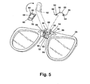
FIG. 5 is a rear exploded view of the corrective lens frame, showing the insertion of the tab in the corrective lens frame. -
FIG. 6 is a rear view similar toFig. 4 showing the vertical adjustment mechanism of the corrective lens frame with respect to the insert, and with the tab in the closed position. -
FIG. 7 is a partial rear perspective view of the respirator mask and removable corrective lens insert shown inFIG. 1 with part of the respirator mask removed to show the insertion pocket. -
FIG. 8 is a sectional view taken along line 7-7 ofFIG. 7 showing a portion of the respirator mask and removable corrective lens insert. - Referring now to the drawings and specifically to
FIG. 1 , arespirator mask assembly 10 comprises amask 12, having afacepiece 14 that fits over the face of a user, atransparent visor 16, a pair of circular orelliptical canister filters 18, and afront module 20 for speech transmission and exhalation functions. The mask is held to the face of the user by a plurality ofharness strap attachments 22 on the periphery of themask 12. Acorrective lens insert 24 is mounted behind thevisor 16 and comprises asupport frame 26, the shape of which conforms to the shape of thevisor 16 and alens frame 28 mounted to thesupport frame 26. - Referring to
FIG. 2 , apocket 30 is integrally molded on the inner side of themask 12 and projects forwardly toward thevisor 16 from thefacepiece 14. Thepocket 30 has a relativelyhorizontal partition 32 that creates twoseparate slots 34 for receiving thesupport frame 26. - Referring now to
FIGS. 3 and 4 , thesupport frame 26 comprises a generally verticalcentral bridge 36 connecting upper and lower portions of theframe 26 having a key hole-shaped slot 38 disposed at the upper joint of the bridge, a plurality ofhorizontal detents 40 on the rear side thereof, and mountinglugs 42 projecting from the generally vertical sides on theframe 26. Thesupport frame 26 is preferably made of a flexible material so that it may be folded in half and is slightly convex so that thelugs 42 point generally rearward. Themounting lugs 42 comprise U-shaped spacedprojections 44 having ramp-like spines 46 that protrude horizontally and laterally from the outer side of thesupport frame 26. - The
lens frame 28 comprises a pair of relativelyrigid lens holders 48 joined by a generallyhorizontal bridge portion 50. Thebridge portion 50 is formed by a relatively rigidcentral piece 52 connected between thelens holders 48 by an insert moldedhinge 54 that spans both sides of thecentral piece 52. Thehinge 54 is flexible so that thelens holders 48 can be folded onto one another. A metal spring 80 (FIG. 5 ) embedded in thehinge 54 biases thelens holders 48 to the position illustrated in the drawings. Thecentral piece 52 includes a pair ofopposed arms 56 that wrap around thecentral bridge 36 of thesupport frame 26. Thecentral piece 26 further has a pair ofchannels 64 that have anangled portion 66 and acatch portion 68 molded on thecentral piece 52 of thelens frame 28. Apivotal tab 58 has multiplehorizontal braces 60 projecting from one side, which are sized to mate with thedetents 40 on thecentral bridge 36. Thetab 58 has adowel 62 mounted at one end and anarrowed end 78. - Referring now to
FIG. 5 , themetal spring 80 and thetab 58 are shown exploded from thelens frame 28. Thespring 80 is formed from a single piece of thin metal wire that has acentral arc 82 withcoils 84 on either end ofarc 82 and leaving straight ends 86 that extend relatively horizontally to thelens holders 48. The ends of thedowell 62 are adapted and shaped to fit into thechannels 64. - To assemble the
corrective lens insert 24, thecentral bridge 36 of thesupport frame 26 is pressed against thecentral piece 52 of thelens frame 28 so thatarms 56 wrap around thecentral bridge 36. Thedowel 62 of thepivotal tab 58 is then fit into theangled portion 66 of thechannels 64 and pushed downwardly and inwardly until it is secured behind thecatch 68. Thetab 58 is pivotally retained by thecatch portion 68 and can pivot around the central axis of thedowel 62. Thetab 58 narrowedend 78 is shaped to fit tightly betweenarms 56 when thetab 58 is pivoted upward. - Referring now to
FIG. 6 , thelens frame 28 is vertically adjustable relative to thesupport frame 26. Thecentral piece 52 is slid along thecentral bridge 36 with thepivotal tab 58 in an open position illustrated inFig. 4 . When thelens frame 28 is in a desired position, thetab 58 is pivoted upwards and towards thecentral piece 52 about thedowel 62 and snapped thereto so that thebraces 60 engage thedetents 40 and thenarrowed end 78 is press-fitted between thearms 56, thereby securing thelens frame 28 at the desired vertical position. - Referring now to
FIG. 7 , thecorrective lens insert 24 is shown attached within themask 12, wherein thekey hole slot 38 in thesupport frame 26 is fitted to aprotuberance 70 projecting from themask 12 above thevisor 16. Theprotuberance 70 has acircular head 72 and acylindrical stem 74 wherein thehead 72 is of slightly greater diameter than thestem 74. Thehead 72 is inserted through the larger portion of thekey hole slot 38 and thesupport frame 26 is pushed downward so that thestem 74 engages the smaller portion of thekey hole slot 38, thereby locking thesupport frame 26 in place in the mask. The mounting lugs 42 (Fig. 4 ) are inserted intopockets 30 located on both sides of thevisor 16. - Referring to
FIG. 8 , the spacedprojections 44 of thesupport frame 26 are received in theslots 34 of thepocket 30 for further attachment of thecorrective lens insert 24 to therespirator mask 12. Thespines 46 on theprojections 44 of the mounting lugs 42 bear against awall 76 of thepocket 30 and releasably retain thecorrective lens insert 24 behind thevisor 16 of therespirator mask 12. - While the invention has been specifically described in connection with certain specific embodiments thereof, it is to be understood that this is by way of illustration and not of limitation, and the scope of the appended claims should be construed as broadly as the prior art will permit.
Claims (8)
- A respirator mask having a face piece (14) adapted to fit on the face of a user and having an opening at the front portion thereof; a visor (16) mounted in the opening for viewing by a mask user; a corrective lens support frame (26) removably mounted to the face piece (14) behind the visor (16); and a corrective lens frame (28) adjustably mounted on the corrective lens support frame (26);
characterised in that:the corrective lens frame (28) has a pivotally mounted locking tab (58) that is movable between locking and unlocking engagement with a central bridge (36) of the support frame (26) for adjustably securing the corrective lens frame (28) in a desired vertical position on the support frame (26). - The respirator mask according to claim 1 wherein the corrective lens frame (28) has an insert molded bridge (50) having a biasing member (80) embedded therein for resiliently flexing the sides of the frame about a central portion thereof.
- The respirator mask according to claim 1 wherein the corrective lens support frame (26) has a shape that conforms to the shape of the visor (16).
- The respirator mask according to claim 1 wherein the support frame (26) has a generally vertical central bridge (36) connecting upper and lower portions of the support frame (26) and has a plurality of vertically arranged, generally horizontal detents (40) on the rear of the bridge (36) that mate with a brace (60) on the corrective lens frame (28) for adjustably securing the corrective lens frame (28) in a desired vertical position on the support frame (26).
- The respirator mask according to any of claims 1-4 wherein the support frame (26) further includes mounting lugs (42) formed on either side of the frame, wherein each of the mounting lugs (42) has spaced projections (44) that are received in pockets (30) on the inner side of the face piece (14).
- The respirator mask according to any of claims 4 or 5 wherein the support frame (26) further has a hole (38) in the central bridge; the inner side of the face piece (14) has a protuberance (70) positioned above the visor (16); and the protuberance (70) is received within the hole (38) in the bridge for partially mounting the support frame (26) on the face piece (14).
- The respirator mask according to any of claims 4-6 wherein the brace (60) is formed on the pivotally mounted locking tab (58) that is movable between locking and unlocking engagement with the central bridge (36) of the support frame (26).
- The respirator mask according to any of claims 1-3 wherein the corrective lens frame (28) has a central piece (52) that includes a pair of opposed arms (56) that wrap around a central bridge (36) of the support frame (26) to sidably mount the corrective lens frame (28) to the support frame (26).
Applications Claiming Priority (2)
| Application Number | Priority Date | Filing Date | Title |
|---|---|---|---|
| US67750905P | 2005-05-04 | 2005-05-04 | |
| PCT/US2006/017072 WO2007040634A2 (en) | 2005-05-04 | 2006-05-04 | Respirator mask with corrective lens frame assembly |
Publications (2)
| Publication Number | Publication Date |
|---|---|
| EP1877144A2 EP1877144A2 (en) | 2008-01-16 |
| EP1877144B1 true EP1877144B1 (en) | 2010-04-21 |
Family
ID=37806076
Family Applications (1)
| Application Number | Title | Priority Date | Filing Date |
|---|---|---|---|
| EP06836063A Expired - Lifetime EP1877144B1 (en) | 2005-05-04 | 2006-05-04 | Respirator mask with corrective lens frame assembly |
Country Status (7)
| Country | Link |
|---|---|
| US (1) | US8113200B2 (en) |
| EP (1) | EP1877144B1 (en) |
| JP (1) | JP4808249B2 (en) |
| KR (1) | KR101263197B1 (en) |
| CA (1) | CA2604171C (en) |
| DE (1) | DE602006013807D1 (en) |
| WO (1) | WO2007040634A2 (en) |
Families Citing this family (15)
| Publication number | Priority date | Publication date | Assignee | Title |
|---|---|---|---|---|
| US7614280B1 (en) * | 2006-03-06 | 2009-11-10 | The United States Of America As Represented By The Secretary Of The Army | Quantitative fit test system and method for assessing respirator biological fit factors |
| US20100065058A1 (en) * | 2008-09-18 | 2010-03-18 | Moldex-Metric, Inc. | Full face respirator mask |
| KR100952333B1 (en) * | 2009-05-29 | 2010-04-09 | 주식회사 산청 | Glasses for gas mask |
| KR101172296B1 (en) | 2010-06-25 | 2012-08-09 | 삼공물산 주식회사 | Gas mask glass for people with low vision |
| US20120125342A1 (en) * | 2010-11-19 | 2012-05-24 | 3M Innovative Properties Company | Filtering face-piece respirator having support structure injection molded to filtering structure |
| US9998687B2 (en) * | 2012-09-12 | 2018-06-12 | Bae Systems Information And Electronic Systems Integration Inc. | Face mounted extreme environment thermal sensor system |
| CN103550875B (en) * | 2013-11-08 | 2016-04-06 | 中国人民解放军第四一一医院 | Anti-poison dust-proof mask |
| KR101539657B1 (en) * | 2014-08-28 | 2015-07-29 | 김종기 | The spectacles of gas mask |
| KR101524217B1 (en) * | 2014-12-16 | 2015-05-29 | 삼공물산 주식회사 | Gas mask having internal airflow |
| US11228738B2 (en) | 2018-01-24 | 2022-01-18 | Darix Sàrl | Head-mountable augmented vision system for displaying thermal images |
| EP3801780B1 (en) | 2018-06-07 | 2024-12-18 | 3M Innovative Properties Company | Respirator configured to accept vision-protecting module |
| DE102019122746B4 (en) * | 2019-08-23 | 2021-04-29 | Prohero Group Co., Ltd. | Fastening device for a spectacle attachment frame |
| CN111035093A (en) * | 2019-11-27 | 2020-04-21 | 深圳市赛领车业科技有限公司 | Bicycle/motorcycle head cover |
| CN114984477A (en) * | 2022-06-23 | 2022-09-02 | 上海呼享环保科技有限公司 | Face mask capable of being loaded with glasses |
| JP1795209S (en) * | 2024-03-20 | 2025-04-04 | Snorkeling Mask |
Family Cites Families (18)
| Publication number | Priority date | Publication date | Assignee | Title |
|---|---|---|---|---|
| US2396207A (en) * | 1942-11-09 | 1946-03-05 | Alfred H Sachs | Lens mounting for gas masks and the like |
| US2737659A (en) * | 1951-11-13 | 1956-03-13 | Acme Prot Equipment Company | Optical gas masks |
| US2905172A (en) * | 1957-01-07 | 1959-09-22 | Acme Prot Equipment Company | Eyeglass mounting for gas masks |
| US3004535A (en) | 1960-03-01 | 1961-10-17 | Carl A Nielson | Optical insert for gas masks |
| DE1171750B (en) | 1960-12-06 | 1964-06-04 | Felix Wulkow Dr Med | Respirator with glasses on the inside |
| US3146295A (en) * | 1961-03-29 | 1964-08-25 | Scott Aviation Corp | Ophthalmic mounting for a face mask |
| US3563640A (en) * | 1968-08-12 | 1971-02-16 | Mine Safety Appliances Co | Device for holding spectacles in a mask |
| DE2646042A1 (en) * | 1976-10-08 | 1978-04-13 | Auergesellschaft Gmbh | Gas mask spectacle holder - has U=shaped frame with legs hooked in inlet air channels and web under visor sealing |
| US4349251A (en) * | 1980-08-11 | 1982-09-14 | Sidney Shedrow | Adjustable eyeglass mounting |
| JPS57200238A (en) | 1981-06-03 | 1982-12-08 | Nippon Telegr & Teleph Corp <Ntt> | Drawing of glass material |
| JPS6143503Y2 (en) * | 1981-06-15 | 1986-12-09 | ||
| US4542965A (en) * | 1983-01-20 | 1985-09-24 | Sidney Shedrow | Suction cup mount for eyeglasses |
| DE3568534D1 (en) * | 1984-12-14 | 1989-04-13 | Avon Ind Polymers | Sight correction attachment for respirators |
| US4711539A (en) * | 1985-06-18 | 1987-12-08 | American Optical Corporation | Support structure for protective mask optical insert |
| US4930163A (en) * | 1988-12-15 | 1990-06-05 | King Mathew B | Apparatus for supporting an eyeglass frame lens assembly in a diving or protective mask |
| US6019468A (en) * | 1998-10-02 | 2000-02-01 | Altemare, Jr.; Kenneth D. | Spectacle kit |
| BE1013165A6 (en) * | 1999-12-01 | 2001-10-02 | Vandeputte Dirk | Spectacle frame for a gasmask |
| US6776485B2 (en) * | 2001-06-05 | 2004-08-17 | Anthony John Cole | Apparatus for attaching spectacles to a facial mask |
-
2006
- 2006-05-04 JP JP2008510187A patent/JP4808249B2/en not_active Expired - Lifetime
- 2006-05-04 WO PCT/US2006/017072 patent/WO2007040634A2/en not_active Ceased
- 2006-05-04 DE DE602006013807T patent/DE602006013807D1/en not_active Expired - Lifetime
- 2006-05-04 KR KR1020077026609A patent/KR101263197B1/en not_active Expired - Lifetime
- 2006-05-04 US US11/913,382 patent/US8113200B2/en active Active
- 2006-05-04 EP EP06836063A patent/EP1877144B1/en not_active Expired - Lifetime
- 2006-05-04 CA CA2604171A patent/CA2604171C/en not_active Expired - Lifetime
Also Published As
| Publication number | Publication date |
|---|---|
| EP1877144A2 (en) | 2008-01-16 |
| WO2007040634A2 (en) | 2007-04-12 |
| CA2604171A1 (en) | 2007-04-12 |
| KR20080003892A (en) | 2008-01-08 |
| JP4808249B2 (en) | 2011-11-02 |
| KR101263197B1 (en) | 2013-05-10 |
| US8113200B2 (en) | 2012-02-14 |
| WO2007040634A3 (en) | 2007-06-07 |
| US20080186447A1 (en) | 2008-08-07 |
| CA2604171C (en) | 2013-07-23 |
| DE602006013807D1 (en) | 2010-06-02 |
| JP2008539886A (en) | 2008-11-20 |
Similar Documents
| Publication | Publication Date | Title |
|---|---|---|
| US8113200B2 (en) | Respirator mask with corrective lens frame assembly | |
| EP1001830B1 (en) | Filtering face mask having one or two straps | |
| US7494218B1 (en) | Adjustable spectacle kit | |
| US5412438A (en) | Sunglasses with detachable prescription eyeglasses | |
| US7204589B2 (en) | Adjustable prescription lens insert for safety eyewear | |
| EP2191736B1 (en) | Wearable protective device | |
| US8550620B2 (en) | Frame hinge and side arm, eyeglass frame with multiple wearer connections and improved spectacle kit | |
| CZ289527B6 (en) | Breathing mask for protection of respiratory tract | |
| CN102341148B (en) | Spectacle frames for masks | |
| JPH0379029B2 (en) | ||
| EP0193325A2 (en) | Optical accessory for use with spectacle frame | |
| CA2346047C (en) | Spectacle kit | |
| US7637611B1 (en) | Adjustable spectacle kit | |
| US8025395B2 (en) | Industrial safety goggles with frame for ophthalmic micas and impact protection mica | |
| EP0821808A1 (en) | Clip-on shield for spectacles | |
| US6325506B1 (en) | Interchangeable eyeglass lens system | |
| CN101466334B (en) | Safety eyewear including a flexible cable attachment | |
| CN217661162U (en) | Face mask capable of being loaded with glasses | |
| US20070115424A1 (en) | Prescription insert for safety eyewear and conversion kit to make a presciption insert into functional eyeglasses | |
| US11086146B1 (en) | Anti-fog and anti-impact rim clip for eye glasses | |
| US20100253903A1 (en) | Bridge for Clip-On Sunglasses and Auxiliary Lenses | |
| CN114984477A (en) | Face mask capable of being loaded with glasses | |
| JP2009540367A (en) | Safety glasses with prescribed inserts | |
| KR100789315B1 (en) | Lens assembly for gas mask with fixed clip and detachable spectacle frame | |
| KR200415990Y1 (en) | Lens assembly for gas mask with fixed clip and detachable spectacle frame |
Legal Events
| Date | Code | Title | Description |
|---|---|---|---|
| PUAI | Public reference made under article 153(3) epc to a published international application that has entered the european phase |
Free format text: ORIGINAL CODE: 0009012 |
|
| 17P | Request for examination filed |
Effective date: 20071001 |
|
| AK | Designated contracting states |
Kind code of ref document: A2 Designated state(s): DE FI FR GB IT |
|
| 17Q | First examination report despatched |
Effective date: 20080418 |
|
| RBV | Designated contracting states (corrected) |
Designated state(s): DE FI FR GB IT |
|
| DAX | Request for extension of the european patent (deleted) | ||
| GRAP | Despatch of communication of intention to grant a patent |
Free format text: ORIGINAL CODE: EPIDOSNIGR1 |
|
| GRAS | Grant fee paid |
Free format text: ORIGINAL CODE: EPIDOSNIGR3 |
|
| GRAA | (expected) grant |
Free format text: ORIGINAL CODE: 0009210 |
|
| AK | Designated contracting states |
Kind code of ref document: B1 Designated state(s): DE FI FR GB IT |
|
| REG | Reference to a national code |
Ref country code: GB Ref legal event code: FG4D |
|
| REF | Corresponds to: |
Ref document number: 602006013807 Country of ref document: DE Date of ref document: 20100602 Kind code of ref document: P |
|
| PLBE | No opposition filed within time limit |
Free format text: ORIGINAL CODE: 0009261 |
|
| STAA | Information on the status of an ep patent application or granted ep patent |
Free format text: STATUS: NO OPPOSITION FILED WITHIN TIME LIMIT |
|
| 26N | No opposition filed |
Effective date: 20110124 |
|
| PGFP | Annual fee paid to national office [announced via postgrant information from national office to epo] |
Ref country code: FI Payment date: 20130424 Year of fee payment: 8 |
|
| PG25 | Lapsed in a contracting state [announced via postgrant information from national office to epo] |
Ref country code: FI Free format text: LAPSE BECAUSE OF NON-PAYMENT OF DUE FEES Effective date: 20140504 |
|
| REG | Reference to a national code |
Ref country code: FR Ref legal event code: PLFP Year of fee payment: 11 |
|
| REG | Reference to a national code |
Ref country code: FR Ref legal event code: PLFP Year of fee payment: 12 |
|
| REG | Reference to a national code |
Ref country code: FR Ref legal event code: PLFP Year of fee payment: 13 |
|
| P01 | Opt-out of the competence of the unified patent court (upc) registered |
Effective date: 20230429 |
|
| PGFP | Annual fee paid to national office [announced via postgrant information from national office to epo] |
Ref country code: DE Payment date: 20250529 Year of fee payment: 20 |
|
| PGFP | Annual fee paid to national office [announced via postgrant information from national office to epo] |
Ref country code: GB Payment date: 20250527 Year of fee payment: 20 |
|
| PGFP | Annual fee paid to national office [announced via postgrant information from national office to epo] |
Ref country code: IT Payment date: 20250521 Year of fee payment: 20 |
|
| PGFP | Annual fee paid to national office [announced via postgrant information from national office to epo] |
Ref country code: FR Payment date: 20250526 Year of fee payment: 20 |
|
| REG | Reference to a national code |
Ref country code: DE Ref legal event code: R071 Ref document number: 602006013807 Country of ref document: DE |