EP1876859A2 - Diaphragm for speaker and manufacturing method therefor - Google Patents
Diaphragm for speaker and manufacturing method therefor Download PDFInfo
- Publication number
- EP1876859A2 EP1876859A2 EP07012367A EP07012367A EP1876859A2 EP 1876859 A2 EP1876859 A2 EP 1876859A2 EP 07012367 A EP07012367 A EP 07012367A EP 07012367 A EP07012367 A EP 07012367A EP 1876859 A2 EP1876859 A2 EP 1876859A2
- Authority
- EP
- European Patent Office
- Prior art keywords
- wooden
- diaphragm
- thin
- thin wooden
- boards
- Prior art date
- Legal status (The legal status is an assumption and is not a legal conclusion. Google has not performed a legal analysis and makes no representation as to the accuracy of the status listed.)
- Granted
Links
Images




Classifications
-
- H—ELECTRICITY
- H04—ELECTRIC COMMUNICATION TECHNIQUE
- H04R—LOUDSPEAKERS, MICROPHONES, GRAMOPHONE PICK-UPS OR LIKE ACOUSTIC ELECTROMECHANICAL TRANSDUCERS; ELECTRIC HEARING AIDS; PUBLIC ADDRESS SYSTEMS
- H04R31/00—Apparatus or processes specially adapted for the manufacture of transducers or diaphragms therefor
- H04R31/003—Apparatus or processes specially adapted for the manufacture of transducers or diaphragms therefor for diaphragms or their outer suspension
-
- H—ELECTRICITY
- H04—ELECTRIC COMMUNICATION TECHNIQUE
- H04R—LOUDSPEAKERS, MICROPHONES, GRAMOPHONE PICK-UPS OR LIKE ACOUSTIC ELECTROMECHANICAL TRANSDUCERS; ELECTRIC HEARING AIDS; PUBLIC ADDRESS SYSTEMS
- H04R7/00—Diaphragms for electromechanical transducers; Cones
- H04R7/02—Diaphragms for electromechanical transducers; Cones characterised by the construction
- H04R7/12—Non-planar diaphragms or cones
-
- H—ELECTRICITY
- H04—ELECTRIC COMMUNICATION TECHNIQUE
- H04R—LOUDSPEAKERS, MICROPHONES, GRAMOPHONE PICK-UPS OR LIKE ACOUSTIC ELECTROMECHANICAL TRANSDUCERS; ELECTRIC HEARING AIDS; PUBLIC ADDRESS SYSTEMS
- H04R2307/00—Details of diaphragms or cones for electromechanical transducers, their suspension or their manufacture covered by H04R7/00 or H04R31/003, not provided for in any of its subgroups
- H04R2307/021—Diaphragms comprising cellulose-like materials, e.g. wood, paper, linen
Definitions
- the present invention relates to diaphragms for speakers and manufacturing methods therefor.
- thin wooden boards are subjected to press working or molding so as to produce diaphragms for use in speakers.
- Japanese Unexamined Patent Application Publication No. H06-178386 teaches that a single sheet of a thin wooden board is subjected to press working so as to produce a diaphragm, or plural sheets of thin wooden boards are laminated together and are then subjected to press working so as to produce a diaphragm. It also teaches that a thin wooden board is formed in a cone shape in advance and is then subjected to press working so as to produce a diaphragm.
- Japanese Unexamined Patent Application Publication No. 2004-254013 teaches that a thin wooden board having a V-shaped cutout is prepared in advance; the thin wooden board is softened by way of the addition of water thereto; opposite sides along the V-shaped cutout are adhered together by way of primary pressing; the thin wooden board after the primary pressing is impregnated with a thermosetting resin; then, the thin wooden board impregnated with the thermosetting resin is subjected to secondary pressing so as to produce a diaphragm.
- thin wooden boards are easily broken or split along the grains thereof during press working or molding.
- the thin wooden board is subjected to steaming prior to molding, or it is subjected to boiling using an alkali solution prior to molding, thus making the thin wooden board have flexibility, whereby it is possible to control the occurrence of cracks during the molding.
- the diaphragm formed by way of press working be subjected to treatment in order to improve the durability thereof. Therefore, a coat of urethane varnish is applied to the thin wooden board after press working.
- the aforementioned manufacturing method is complex because it needs various processes before or after the press working.
- the manufacturing method taught in Japanese Unexamined Patent Application Publication No. 2004-254013 is also complex because it performs press working twice. Since the opposite sides of the V-shaped cutout of the thin wooden board are adhered together, directions of the grains greatly change at the boundary of the adhered portion. This causes irregularity in terms of directions of the grains in the diaphragm, which in turn degrades the acoustic characteristics of the diaphragm or which in turn causes cracks in the diaphragm along specific directions.
- the adhered portion is slightly increased in thickness compared with the thickness of the other portion of the diaphragm. That is, the diaphragm suffers from irregularity in terms of the thickness, which in turn degrades the acoustic characteristics thereof.
- a diaphragm for use in a speaker includes a wooden vibrator that is formed using a plurality of thin wooden boards, which are impregnated with a resin and are integrally laminated together in a laminated structure having a curved shape, and a plurality of high density portions that are elongated in a radial direction from the center to the periphery of the wooden vibrator, wherein the wooden vibrator has a uniformly distributed thickness.
- the high density portion in a plan view is formed in a band-like shape, a wedge-like shape, or a sectorial shape; and the width of the high density portion in a plan view is gradually increased in the direction from the center to the periphery of the wooden vibrator.
- the resin is selected from among an epoxy resin, urethane resin, polyester resin, and acrylic resin.
- the resin content of the wooden vibrator ranges from 10 weight-percent to 70 weight-percent.
- coloring such as dye or pigment is applied to the wooden vibrator as necessary.
- the thickness of the wooden vibrator ranges from 0.2 mm to 0.7 mm.
- the wooden fiber directions of the thin wooden boards integrally laminated together mutually cross with prescribed angles therebetween.
- the wooden fiber directions of three or more thin wooden boards respectively cross with the same angle therebetween.
- N thin wooden boards where "N" is an integer not less than two
- the wooden fiber directions thereof respectively cross with an angle of 360/2N degrees therebetween.
- the wooden vibrator forming the diaphragm has the uniformly distributed thickness irrespective of the formation of the high density portions, it is possible to improve the acoustic characteristics.
- the wooden vibrator is reinforced by means of the high density portions and is thus increased in the mechanical strength thereof; hence, it is possible to increase the degree of freedom in design. Since the rigidity of the wooden vibrator is increased by means of the high density portions, it is possible to improve the durability of the diaphragm against high input signals. Since the thin wooden boards forming the wooden vibrator are impregnated with a resin, it is possible to increase the strength of the wooden vibrator and to avoid the degradation due to aging. Since the wooden fiber directions mutually cross with prescribed angles therebetween, it is possible to further increase the strength of the wooden vibrator.
- a diaphragm for use in a speaker is manufactured by way of impregnating a plurality of thin wooden boards having flat rectangular shapes with a resin, forming a plurality of cutouts, which are elongated in directions along or crossing wooden fiber directions, in each of the thin wooden boards, integrally laminating the thin wooden boards together in such a way that the wooden fiber directions thereof cross each other, and performing thermal pressing on the thin wooden boards integrally laminated together so as to form a wooden vibrator serving as the diaphragm.
- the cutouts are each elongated in a direction from the periphery to the center of the thin wooden board.
- the thin wooden boards are subjected to thermal pressing after the opposite sides of the cutouts thereof are respectively connected together.
- the cutouts it is possible to form a plurality of folded portions, which are elongated in directions along or crossing wooden fiber directions, in each of the thin wooden boards.
- the folded portions are each elongated in a direction from the periphery to the center of the thin wooden board.
- the thin wooden boards are integrally laminated together in such a way that the wooden fiber directions thereof lie along or mutually cross each other.
- the process for forming the cutouts or folded portions can be performed before the process for impregnating the thin wooden board with a resin solution.
- the thin wooden boards are impregnated with a resin in advance and are then subjected to thermal pressing.
- This causes the thin wooden boards to slip on each other during the thermal pressing; hence, it is possible to improve the formability of the wooden vibrator.
- the opposite sides of the cutouts are connected together during the thermal pressing, it is possible to easily form the high density portions, and it is possible to reduce the difference of thickness between the high density portions and the other portions; that is, it is possible to realize the diaphragm having a uniformly distributed thickness.
- the cutouts are formed along the wooden fiber directions, it is possible to improve the strength of the diaphragm because the wooden fibers of the thin wooden boards are not broken by the cutouts.
- the wooden fibers are partially broken so that the wooden fiber lengths are shortened, thus increasing the flexibility of the thin wooden boards. That is, it is possible to further improve the formability of the diaphragm. Since the thin wooden boards are increased in flexibility, it is possible to easily produce any types of diaphragms each having a relatively small radius of curvature. Since the cutouts are each formed in the direction from the periphery to the center of the thin wooden board, it is possible to form the high density portions elongated from the center of the wooden vibrator in a radial manner.
- the thermal pressing is performed after the opposite sides of the cutouts are connected together, it is possible to reliably form the high density portions.
- the thin wooden boards are each formed in a curved shape having a certain curvature. This greatly reduces the amount of deformation of the thin wooden boards during the thermal pressing; hence, it is possible to avoid the occurrence of cracks. Since the thin wooden boards are laminated together in such a way that the wooden fiber directions thereof cross each other, it is possible to further increase the strength of the diaphragm.
- the folded portions are formed in the thin wooden boards, it is possible to easily form the high density portions by way of thermal pressing. Since the folded portions are each formed in the direction from the periphery to the center of the thin wooden board, it is possible to form the high density portions elongated from the center of the wooden vibrator in a radial manner.
- FIG. 1 is a cross-sectional view showing a speaker equipped with a diaphragm in accordance with a preferred embodiment of the present invention.
- FIG. 2 is a plan view showing the diaphragm of the speaker; and
- FIG. 3 is cross-sectional view taken along line A-A in FIG. 2.
- the speaker shown in FIG. 1 includes a diaphragm 1, a center cap 2, a voice coil 4, a collar (or an edge member) 5, a frame 6, and a magnet 7.
- the diaphragm 1 is composed of a wooden vibrator having a cone shape, which is enlarged in diameter externally, wherein the voice coil 4 is attached to a small-diameter end of the diaphragm 1, and a large-diameter periphery of the diaphragm 1 joins the frame 6 via the collar 5.
- the center cap 2 is composed of a wooden vibrator having a semi-spherical shape that projects outwardly so as to cover the cylindrical portion (or a center pole) of the magnet 7 inserted into the voice coil 4 in a non-contact manner.
- the center cap 2 is attached to the small-diameter end of the diaphragm 1.
- a damper (not shown) is additionally arranged between the small-diameter end of the diaphragm 1 and the frame 6 so as to prevent lateral vibration.
- a wiring of the voice coil 4 is extended toward a terminal (not shown) formed at the small-diameter end of the diaphragm 1; hence, the wiring of the voice coil 4 is extracted onto the frame 6 via the terminal.
- the diaphragm 1 is designed to convert a large part of vibration generated by the voice coil 4 into sound.
- the center cap 2 emits sound ranging from intermediate frequencies to high frequencies so as to improve frequency characteristics and sound emission characteristics of the speaker.
- the diaphragm 1 is composed of a wooden vibrator 11, in which plural sheets of thin wooden boards impregnated with a resin are laminated together and are subjected to thermal pressing into a curved shape.
- the wooden vibrator 11 is composed of the resin and the wooden material forming thin wooden boards, which are formed in a curved shape.
- the resin content of the wooden vibrator 11 range from 10 weight-percent to 70 weight-percent. When the resin content is above 10 weight-percent, it is possible to improve the formability and to avoid the degradation of the wooden vibrator 11. When the resin content is below 70 weight-percent, it is possible to improve the acoustic characteristics without causing a reduction of the content of the wooden material in the wooden vibrator 11.
- a through-hole 11a is formed at the center of the wooden vibrator 11.
- the center cap 2 (see FIG. 1) is engaged with the through-hole 11a of the wooden vibrator 11.
- a plurality of high density portions 12 are formed and are elongated from the center to the periphery of the wooden vibrator 11 in a radial manner.
- the high density portions 12 are increased in the wooden density (i.e., the density of the wooden material forming the wooden vibrator 11) in comparison with the other portions of the wooden vibrator 11. It is preferable that the wooden density of the high density portions 12 be approximately 1.3 times higher than the wooden density of the other portions in the wooden vibrator 11.
- the high density portion 12 in a plan view be formed in a band-like shape, a wedge-like shape, or a sectorial shape, for example. It is preferable that the width of the high density portion 12 in a plan view be gradually increased in a direction from the center to the periphery of the wooden vibrator 11. All of the high density portions 12 in a plan view can be formed in the same size; alternatively, the high density portions 12 can be formed in different sizes.
- each of the high density portions 12 has a band-like shape whose width is gradually increased in the direction from the center to the periphery of the wooden vibrator 11. In other words, it has roughly a sectorial shape.
- the high density portions 12 can be easily and visually distinguished from the other portions in plan view by horizontally viewing the wooden vibrator 11 that has deep-colored portions and light-colored portions; that is, the deep-colored portions of the wooden vibrator 11 can be visually recognized as the high density portions 12.
- the wooden vibrator 11 having the high density portions 12 When the wooden vibrator 11 having the high density portions 12 is exposed to visible rays of light, it is possible to recognize the distinction between the prescribed portions having a relatively low light transmission ratio and the other portions having a relatively high light transmission ratio. That is, it is possible to recognize the prescribed portions having a relatively low light transmission ratio as the high density portions 12.
- the wooden vibrator 11 having the high density portions 12 has a uniformly distributed thickness.
- the thickness of the high density portions 12 is substantially identical to the thickness of the other portions in the wooden vibrator 11. It is preferable that the thickness of the wooden vibrator 11 range from 0.2 mm to 0.7 mm. When the thickness is above 0.2 mm, it is unlikely to cause a reduction of the strength and rigidity of the wooden vibrator 11. When the thickness is below 0.7 mm, the rigidity is not increased so much; hence, it is possible to prevent the degradation of the acoustic characteristics.
- the wooden vibrator 11 prefferably includes coloring in addition to the resin. It is possible to use dye or pigment as the coloring.
- the fiber directions of plural thin wooden boards laminated together be crossed with each other.
- the fiber directions can be crossed with the same angle therebetween.
- N thin wooden boards where "N" is an integer not less than two
- the fiber directions of the adjacently joined thin wooden boards are crossed with an angle of 360/2N degrees.
- the high density portions 12 reinforce the wooden vibrator 11, the mechanical strength of which is thus increased. Hence, it is possible to increase the degree of freedom in designing the diaphragm 1. Since the rigidity of the wooden vibrator 11 is increased by means of the high density portions 12, it is possible to reduce partial vibration, thus realizing relatively low distortion in sound. In addition, it is possible to improve the durability of the wooden vibrator 11 against high input signals.
- the wooden vibrator 11 has the uniformly distributed thickness irrespective of the formation of the high density portions 12, it is possible to design the speaker without consideration of detrimental effects regarding a limit to audio frequencies in the reproduction of high tone pitches.
- the wooden vibrator 11 is composed of the thin wooden boards impregnated with the resin, it is possible to further increase the strength of the wooden vibrator 11 and to avoid degradation due to aging.
- a thin wooden board 21 having a flat rectangular shape in plan view, the thickness of which ranges from 0.1 mm to 0.5 mm.
- a through-hole 21 a is formed at the center of the thin wooden board 21.
- Dashed lines indicate wooden fiber lines along which the grains are aligned.
- the thin wooden board 21 having the through-hole 21 a is impregnated with a resin.
- a resin is dissolved into a solvent so as to produce a resin solution, into which the thin wooden board 21 is soaked.
- the resin solution is sprayed or applied to the thin wooden board 21.
- the resin material it is possible to list an epoxy resin, urethane resin, polyester resin, and acrylic resin. It is preferable that the resin content of the thin wooden board 21 range from 10 weight-percent to 70 weight-percent.
- cutouts 22 are formed at prescribed positions along the wooden fiber directions of the thin wooden board 21. It is preferable that two cutouts 22 be formed in directions from the periphery to the center of the thin wooden board 21. It is preferable that the two cutouts 22 be formed symmetrically with each other in the thin wooden board 21.
- the cutouts 22 can be formed in the thin wooden board 21 after the thin wooden board 21 is impregnated with the resin solution.
- opposite sides 22a of the cutouts 22 are connected together so as to form connected portions 22b.
- the connected portions 22b can be subjected to thermal fusion; alternatively, the connected portions 22b can be fixed by use of a stapler (not shown), for example. Due to the formation of the connected portions 22b, the thin wooden board 21 is slightly bent about the through-hole 2 1 a with a certain curvature.
- FIGS. 4A to 4C There are provided three sheets of the thin wooden boards 21, each of which is produced by way of the steps shown in FIGS. 4A to 4C.
- the three sheets of the thin wooden boards 21 are laminated together as shown in FIG. 4D such that the through-holes 21 a thereof are vertically overlapped with each other.
- the three sheets of the thin wooden boards 21 are laminated together such that the wooden fiber directions thereof are respectively crossed with an angle of 120° therebetween.
- an upper mold 31 and a lower mold 32 having Nichrome wires i.e., wires composed of nickel-chromium alloys.
- the three sheets of the thin wooden boards 21, which are laminated together as shown in FIG. 4D, are arranged between the upper mold 31 and the lower mold 32; then, the upper mold 31 and the lower mold 32 are heated by electrifying the Nichrome wires so that the three sheets of the thin wooden boards 21 are subjected to thermal pressing.
- the temperature of the upper mold 31 and the lower mold 32 depends upon the resin impregnated into the thin wooden boards 21, wherein, in the case of the epoxy resin, it is preferable that the temperature range from 100°C to 150°C.
- the pressure applied to the thin wooden boards 21 sandwiched between the upper mold 31 and the lower mold 32 range from 0.1 Pa to 0.3 Pa.
- the heating temperature should not be increased over 150°C because the thin wooden boards 21 are burnt and changed in color.
- the three sheets of the thin wooden boards 21 are integrally laminated together so as to form a laminated structure. Then, the outer periphery of the laminated structure is partially cut out along the dashed lines in FIG. 5B.
- the diaphragm 1 shown in FIGS. 2 and 3 correspond to the through-hole 11a of the wooden vibrator 11; and the connected portions 22b of the thin wooden boards 21 correspond to the high density portions 12.
- the prescribed portions in which two or more sheets of the thin wooden boards 21 are laminated together, be left without being cut out.
- the prescribed portions of the laminated structure, in which the three sheets of the thin wooden boards 21 are laminated together are left without being cut out.
- the thin wooden boards 21 are impregnated with the resin in advance and are then laminated together and subjected to thermal pressing. This makes it possible for the prescribed portions of the thin wooden boards 21 laminated together to easily slip on each other; hence, it is possible to easily perform shaping of the thin wooden boards 21, which are tightly held between the upper mold 31 and the lower mold 32, without causing wrinkles or unwanted lines. That is, the first manufacturing method reliably improves the formability of the wooden vibrator 11.
- the connected portions 22b of the thin wooden boards 11 laminated together correspond to the high density portions 12; hence, it is possible to form the high density portions 12 in a regular pattern.
- the thin wooden boards 21 are easily subjected to shaping without forming wrinkles or lines, it is not possible to cause an irregular pattern of the high density portions 12, which may be caused due to the unwanted formation of wrinkles or lines. This makes it possible to produce the diaphragm 1 having superior acoustic characteristics.
- the thin wooden boards 21 are subjected to thermal pressing after the opposite sides 22a of the cutouts 22 thereof are connected together, it is possible to reliably and precisely form the high density portions 12. Since the opposite sides 22a of the cutouts 22 are connected together, it is possible to form the thin wooden boards 21 having curved shapes, which in turn reduces the amount of deformation applied to the thin wooden boards 21 during the thermal pressing and which in turn prevents the occurrence of cracks.
- the thin wooden boards 21 are subjected to thermal pressing after the opposite sides 22a of the cutouts 22 are connected together, it is possible to reduce the difference of thickness between the connected portions 22b (corresponding to the high density portions 12), at which the opposite sides 22a of the cutouts 22 of the thin wooden boards 21 are connected together, and the other portions; hence, it is possible to produce the diaphragm 1 having the uniformly distributed thickness.
- cutouts 22 are formed in directions from the center to the periphery of the thin wooden boards 21, it is possible to easily form the high density portions 12 extended in a radial direction.
- the thin wooden boards 21 are laminated together in such a way that the wooden fiber directions thereof cross each other, it is possible to further improve the strength of the diaphragm 1.
- the opposite sides 22a of the cutouts 22 are connected together; the cutouts 22 are fixed using the resin or stapler so as to form the connected portions 22b; then, the thin wooden boards 21 laminated together are subjected to thermal pressing.
- thermal pressing it is possible to perform thermal pressing without connecting the cutouts 22 of the thin wooden boards 21.
- the opposite sides 22a of the cutouts 22 are automatically connected together so as to appropriately and easily shape them without causing wrinkles or lines; hence, it is possible to form the laminated structure in which the thin wooden boards 21 are laminated together and in which the high density portions 12 are appropriately formed.
- a thin wooden board 41 having a flat rectangular shape in plan view, in which a circular through-hole 41 a is formed at the center thereof. Similar to the thin wooden board 21 shown in FIG. 4A, the thin wooden board 41 has grains aligned along wooden fiber directions indicated by dashed lines in FIG. 6A. The thin wooden board 41 is impregnated with a resin.
- cutouts 42 are formed at prescribed positions of the thin wooden board 41 in such a way that they are elongated in directions crossing the wooden fiber directions. It is preferable that two cutouts 42 be formed and each be elongated in the direction from the periphery to the center of the thin wooden board 41. It is preferable that the two cutouts 42 be formed symmetrically with each other. Incidentally, the cutouts 42 can be formed in the thin wooden board 41 before the thin wooden board 41 is impregnated with the resin.
- opposite sides 42a of the cutouts 42 are connected together so as to form connected portions 42b.
- the connected portions 42b can be fixed using a resin. Due to the formation of the connected portions 42b, the thin wooden board 41 is curved about the through-hole 41a with a certain curvature.
- the three sheets of the thin wooden boards 41 are laminated together as shown in FIG. 6D such that the through-holes 41a thereof vertically overlap each other.
- the thin wooden boards 41 are mutually laminated together such that the wooden fiber directions thereof cross with an angle of 120° therebetween.
- the cutouts 42 can be formed in any directions crossing the wooden fiber directions of the thin wooden board 41. For example, as shown in FIG. 6E, it is possible to form four cutouts 42 elongated in directions inclining the wooden fiber directions with certain angles therebetween.
- a thin wooden board 51 having a flat rectangular shape in plan view, in which a circular through-hole 51 a is formed at the center thereof.
- the thin wooden board 51 has grains aligned in directions indicated by dashed lines in FIG. 7A.
- the thin wooden board 51 is impregnated with a resin.
- the thin wooden board 51 is partially folded along V-shaped fold lines (see dotted lines), thus forming folded portions 52b lying along wooden fiber directions as shown in FIG. 7C. It is preferable that the folded portions 52b be directed in a direction from the periphery to the center of the thin wooden board 51. It is preferable that a plurality of folded portions 52b be formed symmetrically with respect to the through-hole 51 a serving as the center thereof. In order to fix the folded portions 52b, the folded portions 52b can be subjected to thermal fusion, or they can be fixed using a stapler (not shown). Due to the formation of the folded portions 52b, the thin wooden board 51 is slightly curved about the through-hole 51a with a certain curvature. Incidentally, the folded portions 52b of the thin wooden board 51 can be formed before the thin wooden board 51 is impregnated with a resin solution.
- FIGS. 7A to 7C there are provided three sheets of the thin wooden boards 51, each of which is produced by way of the aforementioned steps shown in FIGS. 7A to 7C.
- the three sheets of the thin wooden boards 51 are laminated together as shown in FIG. 7D in such a way that the through-holes 51a thereof vertically overlap each other. That is, the three sheets of the thin wooden boards 51 are laminated together in such a way that the wooden fiber directions thereof cross with an angle of 120° therebetween.
- the three sheets of the thin wooden boards 51 laminated together are tightly held and are subjected to thermal pressing.
- the thermal pressing the three sheets of the thin wooden boards 51 are integrally laminated together so as to form a laminated structure.
- the outer periphery of the laminated structure is partially cut out so as to produce the diaphragm 1 as shown in FIGS. 2 and 3.
- the through-holes 5 1 a of the thin wooden boards 51 laminated together correspond to the through-hole 11 a of the wooden vibrator 11; and the folded portions 52b of the thin wooden boards 51 laminated together correspond to the high density portions 12.
- the third manufacturing method it is possible to demonstrate the foregoing effects demonstrated by the first and second manufacturing methods.
- the third manufacturing method demonstrates the following effect.
- the third manufacturing method is characterized in that, instead of the cutouts, the folded portions 52b are formed in the thin wooden boards 51, which are then subjected to thermal pressing; hence, it is possible to easily form the high density portions 12. Since no cutout is formed in the thin wooden boards 51, the wooden fibers are not broken; hence, it is possible to further increase the strength of the diaphragm 1.
- two folded portions 52b elongated along the wooden fiber directions as shown in FIGS. 7B and 7C.
- two folded portions can be formed and elongated in directions crossing the wooden fiber directions.
- four folded portions can be formed and elongated in directions inclining the wooden fiber directions with certain angles therebetween.
- the number of thin wooden boards, which are laminated together and are subjected to thermal pressing is not necessarily limited to three; that is, it is possible to use two thin wooden boards or to use four or more thin wooden boards.
- through-holes e.g., through-holes 2 1 a, 41 a, and 51a
Landscapes
- Engineering & Computer Science (AREA)
- Physics & Mathematics (AREA)
- Acoustics & Sound (AREA)
- Signal Processing (AREA)
- Manufacturing & Machinery (AREA)
- Multimedia (AREA)
- Diaphragms For Electromechanical Transducers (AREA)
- Veneer Processing And Manufacture Of Plywood (AREA)
Abstract
Description
- The present invention relates to diaphragms for speakers and manufacturing methods therefor.
- This application claims priority on
Japanese Patent Application No. 2006-185712 - According to the conventionally-known manufacturing methods, thin wooden boards are subjected to press working or molding so as to produce diaphragms for use in speakers.
Japanese Unexamined Patent Application Publication No. H06-178386 -
Japanese Unexamined Patent Application Publication No. 2004-254013 - In general, thin wooden boards are easily broken or split along the grains thereof during press working or molding. For this reason, in the manufacturing method taught in
Japanese Unexamined Patent Application Publication No. H06-178386 - The manufacturing method taught in
Japanese Unexamined Patent Application Publication No. 2004-254013 - It is an object of the present invention to provide a diaphragm for use in a speaker, which is produced by way of a simple manufacturing method without causing defects during press working.
- It is another object of the present invention to provide a diaphragm for use in a speaker, which is improved in strength and acoustic characteristics.
- In a first aspect of the present invention, a diaphragm for use in a speaker includes a wooden vibrator that is formed using a plurality of thin wooden boards, which are impregnated with a resin and are integrally laminated together in a laminated structure having a curved shape, and a plurality of high density portions that are elongated in a radial direction from the center to the periphery of the wooden vibrator, wherein the wooden vibrator has a uniformly distributed thickness. Herein, the high density portion in a plan view is formed in a band-like shape, a wedge-like shape, or a sectorial shape; and the width of the high density portion in a plan view is gradually increased in the direction from the center to the periphery of the wooden vibrator.
- In the above, the resin is selected from among an epoxy resin, urethane resin, polyester resin, and acrylic resin. The resin content of the wooden vibrator ranges from 10 weight-percent to 70 weight-percent. In addition, coloring such as dye or pigment is applied to the wooden vibrator as necessary. Furthermore, the thickness of the wooden vibrator ranges from 0.2 mm to 0.7 mm.
- The wooden fiber directions of the thin wooden boards integrally laminated together mutually cross with prescribed angles therebetween. For example, the wooden fiber directions of three or more thin wooden boards respectively cross with the same angle therebetween. When N thin wooden boards (where "N" is an integer not less than two) are laminated together, the wooden fiber directions thereof respectively cross with an angle of 360/2N degrees therebetween.
- As described above, since the wooden vibrator forming the diaphragm has the uniformly distributed thickness irrespective of the formation of the high density portions, it is possible to improve the acoustic characteristics. The wooden vibrator is reinforced by means of the high density portions and is thus increased in the mechanical strength thereof; hence, it is possible to increase the degree of freedom in design. Since the rigidity of the wooden vibrator is increased by means of the high density portions, it is possible to improve the durability of the diaphragm against high input signals. Since the thin wooden boards forming the wooden vibrator are impregnated with a resin, it is possible to increase the strength of the wooden vibrator and to avoid the degradation due to aging. Since the wooden fiber directions mutually cross with prescribed angles therebetween, it is possible to further increase the strength of the wooden vibrator.
- In a second aspect of the present invention, a diaphragm for use in a speaker is manufactured by way of impregnating a plurality of thin wooden boards having flat rectangular shapes with a resin, forming a plurality of cutouts, which are elongated in directions along or crossing wooden fiber directions, in each of the thin wooden boards, integrally laminating the thin wooden boards together in such a way that the wooden fiber directions thereof cross each other, and performing thermal pressing on the thin wooden boards integrally laminated together so as to form a wooden vibrator serving as the diaphragm. Herein, the cutouts are each elongated in a direction from the periphery to the center of the thin wooden board. In addition, the thin wooden boards are subjected to thermal pressing after the opposite sides of the cutouts thereof are respectively connected together. Instead of the cutouts, it is possible to form a plurality of folded portions, which are elongated in directions along or crossing wooden fiber directions, in each of the thin wooden boards. Herein, the folded portions are each elongated in a direction from the periphery to the center of the thin wooden board. Furthermore, the thin wooden boards are integrally laminated together in such a way that the wooden fiber directions thereof lie along or mutually cross each other. Incidentally, the process for forming the cutouts or folded portions can be performed before the process for impregnating the thin wooden board with a resin solution.
- According to the aforementioned manufacturing method, the thin wooden boards are impregnated with a resin in advance and are then subjected to thermal pressing. This causes the thin wooden boards to slip on each other during the thermal pressing; hence, it is possible to improve the formability of the wooden vibrator.
Since the opposite sides of the cutouts are connected together during the thermal pressing, it is possible to easily form the high density portions, and it is possible to reduce the difference of thickness between the high density portions and the other portions; that is, it is possible to realize the diaphragm having a uniformly distributed thickness. When the cutouts are formed along the wooden fiber directions, it is possible to improve the strength of the diaphragm because the wooden fibers of the thin wooden boards are not broken by the cutouts. When the cutouts are formed in directions crossing the wooden fiber directions, the wooden fibers are partially broken so that the wooden fiber lengths are shortened, thus increasing the flexibility of the thin wooden boards. That is, it is possible to further improve the formability of the diaphragm. Since the thin wooden boards are increased in flexibility, it is possible to easily produce any types of diaphragms each having a relatively small radius of curvature. Since the cutouts are each formed in the direction from the periphery to the center of the thin wooden board, it is possible to form the high density portions elongated from the center of the wooden vibrator in a radial manner. - In addition, since the thermal pressing is performed after the opposite sides of the cutouts are connected together, it is possible to reliably form the high density portions. By connecting together the opposite sides of the cutouts, the thin wooden boards are each formed in a curved shape having a certain curvature. This greatly reduces the amount of deformation of the thin wooden boards during the thermal pressing; hence, it is possible to avoid the occurrence of cracks. Since the thin wooden boards are laminated together in such a way that the wooden fiber directions thereof cross each other, it is possible to further increase the strength of the diaphragm.
- When, instead of the cutouts, the folded portions are formed in the thin wooden boards, it is possible to easily form the high density portions by way of thermal pressing. Since the folded portions are each formed in the direction from the periphery to the center of the thin wooden board, it is possible to form the high density portions elongated from the center of the wooden vibrator in a radial manner.
- These and other objects, aspects, and embodiments of the present invention will be described in more detail with reference to the following drawings, in which:
- FIG. 1 is a cross-sectional view showing a speaker equipped with a diaphragm in accordance with a preferred embodiment of the present invention;
- FIG. 2 is a plan view showing the diaphragm of the speaker;
- FIG. 3 is a cross-sectional view taken along line A-A in FIG. 2;
- FIG. 4A is a plan view for explaining a first step of a first manufacturing method of the diaphragm;
- FIG. 4B is a plan view for explaining a second step of the first manufacturing method of the diaphragm;
- FIG. 4C is a plan view for explaining a third step of the first manufacturing method of the diaphragm;
- FIG. 4D is a plan view for explaining a fourth step of the first manufacturing method of the diaphragm;
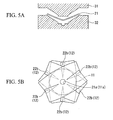
- FIG. 5A is a cross-sectional view for explaining a fifth step of the first manufacturing method of the diaphragm;
- FIG. 5B is a plan view for explaining a sixth step of the first manufacturing method of the diaphragm;
- FIG. 6A is a plan view for explaining a first step of a second manufacturing method of the diaphragm;
- FIG. 6B is a plan view for explaining a second step of the second manufacturing method of the diaphragm;
- FIG. 6C is a plan view for explaining a third step of the second manufacturing method of the diaphragm;
- FIG. 6D is a plan view for explaining a fourth step of the second manufacturing method of the diaphragm;
- FIG. 6E is a plan view showing a variation of a thin wooden board having cutouts for use of the manufacturing of the diaphragm;
- FIG. 7A is a plan view for explaining a first step of a third manufacturing method of the diaphragm;
- FIG. 7B is a plan view for explaining a second step of the third manufacturing method of the diaphragm;
- FIG. 7C is a plan view for explaining a third step of the third manufacturing method of the diaphragm;
- FIG. 7D is a plan view for explaining a fourth step of the third manufacturing method of the diaphragm;
- FIG. 7E is a plan view showing a variation of a thin wooden board having a plurality of folded portions for use in the manufacturing of the diaphragm; and
- FIG. 7F is a plan view showing another variation of the thin wooden board having a plurality of folded portions for use in the manufacturing of the diaphragm.
- The present invention will be described in further detail by way of examples with reference to the accompanying drawings, which are diagrammatically illustrated with sizes and dimensions not necessarily matching actual sizes and dimensions of products.
- FIG. 1 is a cross-sectional view showing a speaker equipped with a diaphragm in accordance with a preferred embodiment of the present invention. FIG. 2 is a plan view showing the diaphragm of the speaker; and FIG. 3 is cross-sectional view taken along line A-A in FIG. 2.
- The speaker shown in FIG. 1 includes a
diaphragm 1, acenter cap 2, avoice coil 4, a collar (or an edge member) 5, aframe 6, and amagnet 7. - The
diaphragm 1 is composed of a wooden vibrator having a cone shape, which is enlarged in diameter externally, wherein thevoice coil 4 is attached to a small-diameter end of thediaphragm 1, and a large-diameter periphery of thediaphragm 1 joins theframe 6 via thecollar 5. - The
center cap 2 is composed of a wooden vibrator having a semi-spherical shape that projects outwardly so as to cover the cylindrical portion (or a center pole) of themagnet 7 inserted into thevoice coil 4 in a non-contact manner. Thecenter cap 2 is attached to the small-diameter end of thediaphragm 1. - A damper (not shown) is additionally arranged between the small-diameter end of the
diaphragm 1 and theframe 6 so as to prevent lateral vibration. A wiring of thevoice coil 4 is extended toward a terminal (not shown) formed at the small-diameter end of thediaphragm 1; hence, the wiring of thevoice coil 4 is extracted onto theframe 6 via the terminal. - In the speaker of FIG. 1, the
diaphragm 1 is designed to convert a large part of vibration generated by thevoice coil 4 into sound. Thecenter cap 2 emits sound ranging from intermediate frequencies to high frequencies so as to improve frequency characteristics and sound emission characteristics of the speaker. - More specifically, as shown in FIG. 2, the
diaphragm 1 is composed of awooden vibrator 11, in which plural sheets of thin wooden boards impregnated with a resin are laminated together and are subjected to thermal pressing into a curved shape. In other words, thewooden vibrator 11 is composed of the resin and the wooden material forming thin wooden boards, which are formed in a curved shape. - It is possible to list various wooden materials for use in the formation of the thin wooden boards forming the
wooden vibrator 11, such as birch, linden, beech, oak, cherry, spruce, maple, walnut, cedar, hinoki, red cedar, agatized wood, horse chestnut, elm, zelkova, and sapele. It is possible to list various resin materials impregnated into the thin wooden boards, such as an epoxy resin, urethane resin, polyester resin, and acrylic resin. Due to the resin impregnation, it is possible to improve the formability during the press working, and it is possible to avoid the degradation of thewooden vibrator 11. - It is preferable that the resin content of the
wooden vibrator 11 range from 10 weight-percent to 70 weight-percent. When the resin content is above 10 weight-percent, it is possible to improve the formability and to avoid the degradation of thewooden vibrator 11. When the resin content is below 70 weight-percent, it is possible to improve the acoustic characteristics without causing a reduction of the content of the wooden material in thewooden vibrator 11. - A through-
hole 11a is formed at the center of thewooden vibrator 11. The center cap 2 (see FIG. 1) is engaged with the through-hole 11a of thewooden vibrator 11. A plurality ofhigh density portions 12 are formed and are elongated from the center to the periphery of thewooden vibrator 11 in a radial manner. Thehigh density portions 12 are increased in the wooden density (i.e., the density of the wooden material forming the wooden vibrator 11) in comparison with the other portions of thewooden vibrator 11. It is preferable that the wooden density of thehigh density portions 12 be approximately 1.3 times higher than the wooden density of the other portions in thewooden vibrator 11. - It is preferable that the
high density portion 12 in a plan view be formed in a band-like shape, a wedge-like shape, or a sectorial shape, for example. It is preferable that the width of thehigh density portion 12 in a plan view be gradually increased in a direction from the center to the periphery of thewooden vibrator 11. All of thehigh density portions 12 in a plan view can be formed in the same size; alternatively, thehigh density portions 12 can be formed in different sizes. - In FIG. 2, each of the
high density portions 12 has a band-like shape whose width is gradually increased in the direction from the center to the periphery of thewooden vibrator 11. In other words, it has roughly a sectorial shape. - The
high density portions 12 can be easily and visually distinguished from the other portions in plan view by horizontally viewing thewooden vibrator 11 that has deep-colored portions and light-colored portions; that is, the deep-colored portions of thewooden vibrator 11 can be visually recognized as thehigh density portions 12. - When the
wooden vibrator 11 having thehigh density portions 12 is exposed to visible rays of light, it is possible to recognize the distinction between the prescribed portions having a relatively low light transmission ratio and the other portions having a relatively high light transmission ratio. That is, it is possible to recognize the prescribed portions having a relatively low light transmission ratio as thehigh density portions 12. - The
wooden vibrator 11 having thehigh density portions 12 has a uniformly distributed thickness. In other words, the thickness of thehigh density portions 12 is substantially identical to the thickness of the other portions in thewooden vibrator 11. It is preferable that the thickness of thewooden vibrator 11 range from 0.2 mm to 0.7 mm. When the thickness is above 0.2 mm, it is unlikely to cause a reduction of the strength and rigidity of thewooden vibrator 11. When the thickness is below 0.7 mm, the rigidity is not increased so much; hence, it is possible to prevent the degradation of the acoustic characteristics. - It is possible for the
wooden vibrator 11 to include coloring in addition to the resin. It is possible to use dye or pigment as the coloring. - It is preferable that the fiber directions of plural thin wooden boards laminated together be crossed with each other. For example, the fiber directions can be crossed with the same angle therebetween. Suppose that N thin wooden boards (where "N" is an integer not less than two) are laminated together. In this case, the fiber directions of the adjacently joined thin wooden boards are crossed with an angle of 360/2N degrees.
- Due to the lamination of the thin wooden boards whose fiber directions cross each other, it is possible to improve the uniformity of vibration in the
wooden vibrator 11; hence, it is possible to improve the acoustic characteristics. In addition, due to the mutually crossed fiber directions of the thin wooden boards, it is possible to further improve the mechanical strength of thewooden vibrator 11. - Due to the formation of the
high density portions 12 in thewooden vibrator 11 adapted to thediaphragm 1, it is possible to realize fragmentarily different wooden densities in thewooden vibrator 11, which in turn realizes the distribution of natural resonance. Due to the distribution of natural resonance, it is unlikely to cause peaks in high-frequency ranges due to natural resonance; hence, it is possible to improve the acoustic characteristics. - In addition, the
high density portions 12 reinforce thewooden vibrator 11, the mechanical strength of which is thus increased. Hence, it is possible to increase the degree of freedom in designing thediaphragm 1. Since the rigidity of thewooden vibrator 11 is increased by means of thehigh density portions 12, it is possible to reduce partial vibration, thus realizing relatively low distortion in sound. In addition, it is possible to improve the durability of thewooden vibrator 11 against high input signals. - Furthermore, since the
wooden vibrator 11 has the uniformly distributed thickness irrespective of the formation of thehigh density portions 12, it is possible to design the speaker without consideration of detrimental effects regarding a limit to audio frequencies in the reproduction of high tone pitches. - Since the
wooden vibrator 11 is composed of the thin wooden boards impregnated with the resin, it is possible to further increase the strength of thewooden vibrator 11 and to avoid degradation due to aging. - Since the fiber directions of the thin wooden boards forming the
wooden vibrator 11 cross each other with prescribed angles therebetween, it is possible to further increase the strength of thewooden vibrator 11 adapted to thediaphragm 1. - Next, a first manufacturing method of the
diaphragm 1 will be described with reference to FIGS. 4A to 4D and FIGS. 5A and 5B. - As shown in FIG. 4A, there is provided a thin
wooden board 21 having a flat rectangular shape in plan view, the thickness of which ranges from 0.1 mm to 0.5 mm. A through-hole 21 a is formed at the center of the thinwooden board 21. Dashed lines indicate wooden fiber lines along which the grains are aligned. - Next, the thin
wooden board 21 having the through-hole 21 a is impregnated with a resin. For example, a resin is dissolved into a solvent so as to produce a resin solution, into which the thinwooden board 21 is soaked. Alternatively, the resin solution is sprayed or applied to the thinwooden board 21. - As the resin material, it is possible to list an epoxy resin, urethane resin, polyester resin, and acrylic resin. It is preferable that the resin content of the thin
wooden board 21 range from 10 weight-percent to 70 weight-percent. - Next, as shown in FIG. 4B,
cutouts 22 are formed at prescribed positions along the wooden fiber directions of the thinwooden board 21. It is preferable that twocutouts 22 be formed in directions from the periphery to the center of the thinwooden board 21. It is preferable that the twocutouts 22 be formed symmetrically with each other in the thinwooden board 21. - Incidentally, the
cutouts 22 can be formed in the thinwooden board 21 after the thinwooden board 21 is impregnated with the resin solution. - Next, as shown in FIG. 4C,
opposite sides 22a of thecutouts 22 are connected together so as to formconnected portions 22b. In order to fix theconnected portions 22b, theconnected portions 22b can be subjected to thermal fusion; alternatively, theconnected portions 22b can be fixed by use of a stapler (not shown), for example. Due to the formation of theconnected portions 22b, the thinwooden board 21 is slightly bent about the through-hole 2 1 a with a certain curvature. - There are provided three sheets of the thin
wooden boards 21, each of which is produced by way of the steps shown in FIGS. 4A to 4C. The three sheets of the thinwooden boards 21 are laminated together as shown in FIG. 4D such that the through-holes 21 a thereof are vertically overlapped with each other. In the case of FIG. 4D, the three sheets of the thinwooden boards 21 are laminated together such that the wooden fiber directions thereof are respectively crossed with an angle of 120° therebetween. - Next, as shown in FIG. 5A, there are provided an
upper mold 31 and alower mold 32 having Nichrome wires (i.e., wires composed of nickel-chromium alloys). The three sheets of the thinwooden boards 21, which are laminated together as shown in FIG. 4D, are arranged between theupper mold 31 and thelower mold 32; then, theupper mold 31 and thelower mold 32 are heated by electrifying the Nichrome wires so that the three sheets of the thinwooden boards 21 are subjected to thermal pressing. The temperature of theupper mold 31 and thelower mold 32 depends upon the resin impregnated into the thinwooden boards 21, wherein, in the case of the epoxy resin, it is preferable that the temperature range from 100°C to 150°C. In addition, it is preferable that the pressure applied to the thinwooden boards 21 sandwiched between theupper mold 31 and thelower mold 32 range from 0.1 Pa to 0.3 Pa. Herein, the heating temperature should not be increased over 150°C because the thinwooden boards 21 are burnt and changed in color. - By way of the thermal pressing, the three sheets of the thin
wooden boards 21 are integrally laminated together so as to form a laminated structure. Then, the outer periphery of the laminated structure is partially cut out along the dashed lines in FIG. 5B. Thus, it is possible to produce thediaphragm 1 shown in FIGS. 2 and 3. Herein, the through-holes 21a of the thinwooden boards 21 laminated together correspond to the through-hole 11a of thewooden vibrator 11; and theconnected portions 22b of the thinwooden boards 21 correspond to thehigh density portions 12. It is preferable that, during the cutting process of the outer periphery of the laminated structure, the prescribed portions, in which two or more sheets of the thinwooden boards 21 are laminated together, be left without being cut out. In the case of FIG. 5B, the prescribed portions of the laminated structure, in which the three sheets of the thinwooden boards 21 are laminated together, are left without being cut out. - According to the first manufacturing method of the
diaphragm 1, the thinwooden boards 21 are impregnated with the resin in advance and are then laminated together and subjected to thermal pressing. This makes it possible for the prescribed portions of the thinwooden boards 21 laminated together to easily slip on each other; hence, it is possible to easily perform shaping of the thinwooden boards 21, which are tightly held between theupper mold 31 and thelower mold 32, without causing wrinkles or unwanted lines. That is, the first manufacturing method reliably improves the formability of thewooden vibrator 11. - The
connected portions 22b of the thinwooden boards 11 laminated together correspond to thehigh density portions 12; hence, it is possible to form thehigh density portions 12 in a regular pattern. - Since the thin
wooden boards 21 are easily subjected to shaping without forming wrinkles or lines, it is not possible to cause an irregular pattern of thehigh density portions 12, which may be caused due to the unwanted formation of wrinkles or lines. This makes it possible to produce thediaphragm 1 having superior acoustic characteristics. - Since the thin
wooden boards 21 are subjected to thermal pressing after theopposite sides 22a of thecutouts 22 thereof are connected together, it is possible to reliably and precisely form thehigh density portions 12. Since theopposite sides 22a of thecutouts 22 are connected together, it is possible to form the thinwooden boards 21 having curved shapes, which in turn reduces the amount of deformation applied to the thinwooden boards 21 during the thermal pressing and which in turn prevents the occurrence of cracks. - Since the thin
wooden boards 21 are subjected to thermal pressing after theopposite sides 22a of thecutouts 22 are connected together, it is possible to reduce the difference of thickness between theconnected portions 22b (corresponding to the high density portions 12), at which theopposite sides 22a of thecutouts 22 of the thinwooden boards 21 are connected together, and the other portions; hence, it is possible to produce thediaphragm 1 having the uniformly distributed thickness. - Due to the formation of the
plural cutouts 22 along the wooden fiber directions, it is possible to prevent the wooden fibers of the thinwooden boards 21 from being divided via thecutouts 22; hence, it is possible to improve the strength of thediaphragm 1. - Since the
cutouts 22 are formed in directions from the center to the periphery of the thinwooden boards 21, it is possible to easily form thehigh density portions 12 extended in a radial direction. - Since the thin
wooden boards 21 are laminated together in such a way that the wooden fiber directions thereof cross each other, it is possible to further improve the strength of thediaphragm 1. - In the first manufacturing method, the
opposite sides 22a of thecutouts 22 are connected together; thecutouts 22 are fixed using the resin or stapler so as to form theconnected portions 22b; then, the thinwooden boards 21 laminated together are subjected to thermal pressing. However, it is possible to perform thermal pressing without connecting thecutouts 22 of the thinwooden boards 21. In this case, when the thinwooden boards 21 laminated together are held between theupper mold 31 and thelower mold 32, theopposite sides 22a of thecutouts 22 are automatically connected together so as to appropriately and easily shape them without causing wrinkles or lines; hence, it is possible to form the laminated structure in which the thinwooden boards 21 are laminated together and in which thehigh density portions 12 are appropriately formed. - Next, a second manufacturing method of the
diaphragm 1 will be described with reference to FIGS. 6A to 6D. - As shown in FIG. 6A, there is provided a thin
wooden board 41 having a flat rectangular shape in plan view, in which a circular through-hole 41 a is formed at the center thereof. Similar to the thinwooden board 21 shown in FIG. 4A, the thinwooden board 41 has grains aligned along wooden fiber directions indicated by dashed lines in FIG. 6A. The thinwooden board 41 is impregnated with a resin. - Next, as shown in FIG. 6B,
cutouts 42 are formed at prescribed positions of the thinwooden board 41 in such a way that they are elongated in directions crossing the wooden fiber directions. It is preferable that twocutouts 42 be formed and each be elongated in the direction from the periphery to the center of the thinwooden board 41. It is preferable that the twocutouts 42 be formed symmetrically with each other. Incidentally, thecutouts 42 can be formed in the thinwooden board 41 before the thinwooden board 41 is impregnated with the resin. - Next, as shown in FIG. 6C,
opposite sides 42a of thecutouts 42 are connected together so as to formconnected portions 42b. Theconnected portions 42b can be fixed using a resin. Due to the formation of theconnected portions 42b, the thinwooden board 41 is curved about the through-hole 41a with a certain curvature. - There are provided three sheets of the thin
wooden boards 41, each of which is produced by way of the aforementioned steps shown in FIGS. 6A to 6C. The three sheets of the thinwooden boards 41 are laminated together as shown in FIG. 6D such that the through-holes 41a thereof vertically overlap each other. Herein, the thinwooden boards 41 are mutually laminated together such that the wooden fiber directions thereof cross with an angle of 120° therebetween. - Thereafter, similar to the first manufacturing method, there are provided upper and lower molds having Nichrome wires (not shown), between which the three sheets of the thin
wooden boards 41 laminated together are tightly held and are then subjected to thermal pressing. By way of the thermal pressing, the three sheets of the thinwooden boards 41 are integrally laminated together to form a laminated structure. Then, the outer periphery of the laminated structure is partially cut out, thus forming thediaphragm 1 as shown in FIGS. 2 and 3. Herein, the through-holes 41a of the thinwooden boards 41 correspond to the through-hole 11a of thewooden vibrator 11; and theconnected portions 42b of the thinwooden boards 41 laminated together correspond to thehigh density portions 12. - According to the second manufacturing method of the
diaphragm 1, it is possible to demonstrate the foregoing effects demonstrated by the first manufacturing method. - Specifically, due to the formation of the
cutouts 42 along the directions crossing the wooden fiber directions of the thinwooden board 41, wooden fibers are partially broken by way of thecutouts 42 so that the wooden fiber length of the thinwooden board 41 is shortened so as to increase the flexibility of the thinwooden board 41. This makes it possible for the thinwooden board 41, which is tightly held between the upper and lower molds, to be easily shaped without forming wrinkles or lines during the thermal pressing. Due to the increased flexibility of the thinwooden board 41, it is possible to easily form thediaphragm 1 having a relatively small radius of curvature. Incidentally, thecutouts 42 can be formed in any directions crossing the wooden fiber directions of the thinwooden board 41. For example, as shown in FIG. 6E, it is possible to form fourcutouts 42 elongated in directions inclining the wooden fiber directions with certain angles therebetween. - Next, a third manufacturing method of the
diaphragm 1 will be described with reference to FIGS. 7A to 7D. - Similar to the first and second manufacturing methods, there is provided a thin
wooden board 51 having a flat rectangular shape in plan view, in which a circular through-hole 51 a is formed at the center thereof. The thinwooden board 51 has grains aligned in directions indicated by dashed lines in FIG. 7A. The thinwooden board 51 is impregnated with a resin. - Next, as shown in FIG. 7B, the thin
wooden board 51 is partially folded along V-shaped fold lines (see dotted lines), thus forming foldedportions 52b lying along wooden fiber directions as shown in FIG. 7C. It is preferable that the foldedportions 52b be directed in a direction from the periphery to the center of the thinwooden board 51. It is preferable that a plurality of foldedportions 52b be formed symmetrically with respect to the through-hole 51 a serving as the center thereof. In order to fix the foldedportions 52b, the foldedportions 52b can be subjected to thermal fusion, or they can be fixed using a stapler (not shown). Due to the formation of the foldedportions 52b, the thinwooden board 51 is slightly curved about the through-hole 51a with a certain curvature. Incidentally, the foldedportions 52b of the thinwooden board 51 can be formed before the thinwooden board 51 is impregnated with a resin solution. - Next, there are provided three sheets of the thin
wooden boards 51, each of which is produced by way of the aforementioned steps shown in FIGS. 7A to 7C.
The three sheets of the thinwooden boards 51 are laminated together as shown in FIG. 7D in such a way that the through-holes 51a thereof vertically overlap each other. That is, the three sheets of the thinwooden boards 51 are laminated together in such a way that the wooden fiber directions thereof cross with an angle of 120° therebetween. - Thereafter, similar to the first and second manufacturing methods, there are provided upper and lower molds having Nichrome wires, between which the three sheets of the thin
wooden boards 51 laminated together are tightly held and are subjected to thermal pressing. By way of the thermal pressing, the three sheets of the thinwooden boards 51 are integrally laminated together so as to form a laminated structure. Then, the outer periphery of the laminated structure is partially cut out so as to produce thediaphragm 1 as shown in FIGS. 2 and 3. Herein, the through-holes 5 1 a of the thinwooden boards 51 laminated together correspond to the through-hole 11 a of thewooden vibrator 11; and the foldedportions 52b of the thinwooden boards 51 laminated together correspond to thehigh density portions 12. - According to the third manufacturing method, it is possible to demonstrate the foregoing effects demonstrated by the first and second manufacturing methods. In addition, the third manufacturing method demonstrates the following effect.
- That is, the third manufacturing method is characterized in that, instead of the cutouts, the folded
portions 52b are formed in the thinwooden boards 51, which are then subjected to thermal pressing; hence, it is possible to easily form thehigh density portions 12. Since no cutout is formed in the thinwooden boards 51, the wooden fibers are not broken; hence, it is possible to further increase the strength of thediaphragm 1. - Incidentally, it is not necessary to form the two folded
portions 52b elongated along the wooden fiber directions as shown in FIGS. 7B and 7C. For example, as shown in FIG. 7E, two folded portions can be formed and elongated in directions crossing the wooden fiber directions. Alternatively, as shown in FIG. 7F, four folded portions can be formed and elongated in directions inclining the wooden fiber directions with certain angles therebetween. - Moreover, the number of thin wooden boards, which are laminated together and are subjected to thermal pressing, is not necessarily limited to three; that is, it is possible to use two thin wooden boards or to use four or more thin wooden boards. Herein, through-holes (e.g., through-
holes 2 1 a, 41 a, and 51a) are not necessarily formed before the impregnation of the resin and can be formed after the thermal pressing. - Lastly, the present invention is not necessarily limited to the aforementioned embodiment and the aforementioned manufacturing methods; hence, it is possible to realize variations within the scope of the invention defined by the appended claims.
Claims (12)
- A diaphragm for use in a speaker, comprising:a wooden vibrator that is formed using a plurality of thin wooden boards, which are impregnated with a resin and are integrally laminated together in a laminated structure having a curved shape; anda plurality of high density portions that are elongated in a radial direction from a center to a periphery of the wooden vibrator,wherein the wooden vibrator has a uniformly distributed thickness.
- The diaphragm for use in a speaker according to claim 1, wherein the resin is selected from among an epoxy resin, a urethane resin, a polyester resin, and an acrylic resin.
- The diaphragm for use in a speaker according to claim 1, wherein a resin content of the wooden vibrator ranges from 10 weight-percent to 70 weight-percent.
- The diaphragm for use in a speaker according to claim 1, wherein coloring is applied to the wooden vibrator.
- The diaphragm for use in a speaker according to claim 1, wherein the thickness of the wooden vibrator ranges from 0.2 mm to 0.7 mm.
- The diaphragm for use in a speaker according to claim 1, wherein wooden fiber directions of the thin wooden boards integrally laminated together mutually cross with a prescribed angle therebetween.
- A manufacturing method of a diaphragm for use in a speaker, comprising the steps of:impregnating a plurality of thin wooden boards having flat rectangular shapes with a resin;forming a plurality of cutouts, which are elongated in directions along or crossing wooden fiber directions, in each of the plurality of thin wooden boards;integrally laminating the plurality of thin wooden boards together in such a way that the wooden fiber directions thereof cross each other; andperforming thermal pressing on the plurality of thin wooden boards integrally laminated together so as to form a wooden vibrator serving as the diaphragm.
- The manufacturing method of the diaphragm for use in a speaker according to claim 7, wherein the plurality of cutouts are each elongated in a direction from a periphery to a center of the thin wooden board.
- The manufacturing method of the diaphragm for use in a speaker according to claim 7, wherein the plurality of thin wooden boards are subjected to thermal pressing after opposite sides of the cutouts thereof are respectively connected together.
- A manufacturing method of a diaphragm for use in a speaker, comprising the steps of:impregnating a plurality of thin wooden boards having flat rectangular shapes with a resin;forming a plurality of folded portions, which are elongated in directions along or crossing wooden fiber directions, in each of the plurality of thin wooden boards;integrally laminating the plurality of thin wooden boards together in such a way that the wooden fiber directions thereof cross each other; andperforming thermal pressing on the plurality of thin wooden boards integrally laminated together so as to form a wooden vibrator serving as the diaphragm.
- The manufacturing method of the diaphragm for use in a speaker according to claim 10, wherein the plurality of folded portions are each elongated from a periphery to a center of the thin wooden board.
- The manufacturing method of the diaphragm for use in a speaker according to claim 10, wherein the plurality of thin wooden boards are integrally laminated together in such a way that the wooden fiber directions thereof mutually cross each other.
Applications Claiming Priority (1)
| Application Number | Priority Date | Filing Date | Title |
|---|---|---|---|
| JP2006185712A JP4779837B2 (en) | 2006-07-05 | 2006-07-05 | Speaker diaphragm and method for manufacturing speaker diaphragm |
Publications (3)
| Publication Number | Publication Date |
|---|---|
| EP1876859A2 true EP1876859A2 (en) | 2008-01-09 |
| EP1876859A3 EP1876859A3 (en) | 2010-05-12 |
| EP1876859B1 EP1876859B1 (en) | 2011-09-14 |
Family
ID=38565889
Family Applications (1)
| Application Number | Title | Priority Date | Filing Date |
|---|---|---|---|
| EP07012367A Not-in-force EP1876859B1 (en) | 2006-07-05 | 2007-06-25 | Manufacturing method for speaker diaphragm |
Country Status (5)
| Country | Link |
|---|---|
| US (1) | US7775319B2 (en) |
| EP (1) | EP1876859B1 (en) |
| JP (1) | JP4779837B2 (en) |
| CN (1) | CN101102619B (en) |
| AT (1) | ATE524934T1 (en) |
Cited By (1)
| Publication number | Priority date | Publication date | Assignee | Title |
|---|---|---|---|---|
| CN102387449B (en) * | 2007-08-10 | 2015-05-06 | Jvc建伍株式会社 | Acoustic diaphragm and speaker |
Families Citing this family (9)
| Publication number | Priority date | Publication date | Assignee | Title |
|---|---|---|---|---|
| US7845461B2 (en) * | 2007-08-10 | 2010-12-07 | Victor Company Of Japan, Limited | Acoustic diaphragm and speaker |
| CN102170603B (en) * | 2011-05-20 | 2014-01-22 | 深圳麦博电器有限公司 | Mechanical frequency division diaphragm and manufacturing method thereof |
| US9402134B2 (en) * | 2014-09-19 | 2016-07-26 | Merry Electronics (Suzhou) Co., Ltd. | Manufacturing method for stiffened diaphragm and the manufactured diaphragm using same |
| WO2017147190A1 (en) * | 2016-02-24 | 2017-08-31 | Dolby Laboratories Licensing Corporation | Planar loudspeaker manifold for improved sound dispersion |
| TWI767892B (en) * | 2016-11-04 | 2022-06-21 | 香港商比特聯創(控股)有限公司 | Diaphragm for speaker |
| US10735880B2 (en) * | 2017-05-09 | 2020-08-04 | Sonos, Inc. | Systems and methods of forming audio transducer diaphragms |
| USD943551S1 (en) * | 2019-05-23 | 2022-02-15 | Tymphany Acoustic Technology (Huizhou) Co., Ltd. | Diaphragm for loudspeaker |
| US11202153B2 (en) * | 2019-07-29 | 2021-12-14 | Fortemedia, Inc. | MEMS microphone |
| CN111711905B (en) * | 2020-06-24 | 2021-08-17 | 歌尔微电子有限公司 | Miniature Microphone Dustproof Device and MEMS Microphone |
Family Cites Families (22)
| Publication number | Priority date | Publication date | Assignee | Title |
|---|---|---|---|---|
| US1917013A (en) * | 1930-12-27 | 1933-07-04 | Bell Telephone Labor Inc | Sound translating device |
| US4100992A (en) * | 1974-08-12 | 1978-07-18 | Weber Louis Rehde | Loudspeaker |
| JPS61118098A (en) * | 1984-11-14 | 1986-06-05 | Pioneer Electronic Corp | Diaphragm for electroacoustic transducer |
| JPH0728478B2 (en) * | 1984-12-28 | 1995-03-29 | 幅 秀幸 | Speaker |
| JPS62224196A (en) * | 1986-03-25 | 1987-10-02 | Chubu Koon Seisakusho:Kk | Loudspeaker |
| JPS6482896A (en) * | 1987-09-25 | 1989-03-28 | Matsushita Electric Industrial Co Ltd | Diaphragm for loudspeaker |
| JP2690104B2 (en) * | 1988-05-13 | 1997-12-10 | 加藤 義之 | Speaker cone and speaker equipped with the cone |
| US5274199A (en) * | 1990-05-18 | 1993-12-28 | Sony Corporation | Acoustic diaphragm and method for producing same |
| JPH0583791A (en) | 1991-05-23 | 1993-04-02 | Yamaha Corp | Acoustic diaphragm and its manufacture |
| JPH0583792A (en) | 1991-05-23 | 1993-04-02 | Yamaha Corp | Acoustic diaphragm and its manufacture |
| US5329072A (en) * | 1991-05-23 | 1994-07-12 | Yamaha Corporation | Acoustic diaphragm |
| US5256837A (en) * | 1991-10-30 | 1993-10-26 | Pak Il Y | Paper cone for cone type speaker |
| JPH06178386A (en) * | 1992-12-04 | 1994-06-24 | Onkyo Corp | Diaphragm for cone speaker and manufacturing method thereof |
| TW354866B (en) * | 1994-03-31 | 1999-03-21 | Matsushita Electric Industrial Co Ltd | Loudspeaker and a method for producing the same |
| JP2000059883A (en) * | 1998-08-06 | 2000-02-25 | Victor Co Of Japan Ltd | Diaphragm of speaker |
| US6929091B2 (en) * | 2002-10-28 | 2005-08-16 | Sound Advance Systems, Inc. | Planar diaphragm loudspeaker and related methods |
| US7467686B2 (en) * | 2003-02-19 | 2008-12-23 | Victor Company Of Japan, Limited | Speaker diaphragms, manufacturing methods of the same, and dynamic speakers |
| JP3882762B2 (en) * | 2003-02-19 | 2007-02-21 | 日本ビクター株式会社 | Speaker diaphragm |
| JP2004357130A (en) * | 2003-05-30 | 2004-12-16 | Og Corp | Speaker diaphragm |
| JP2005191993A (en) * | 2003-12-26 | 2005-07-14 | Mitsubishi Plastics Ind Ltd | Speaker diaphragm |
| JP4230940B2 (en) * | 2004-03-11 | 2009-02-25 | 株式会社ケンウッド | Speaker diaphragm and method for manufacturing speaker diaphragm |
| US7845461B2 (en) * | 2007-08-10 | 2010-12-07 | Victor Company Of Japan, Limited | Acoustic diaphragm and speaker |
-
2006
- 2006-07-05 JP JP2006185712A patent/JP4779837B2/en not_active Expired - Fee Related
-
2007
- 2007-06-22 US US11/767,249 patent/US7775319B2/en not_active Expired - Fee Related
- 2007-06-25 EP EP07012367A patent/EP1876859B1/en not_active Not-in-force
- 2007-06-25 AT AT07012367T patent/ATE524934T1/en not_active IP Right Cessation
- 2007-07-03 CN CN2007101278230A patent/CN101102619B/en not_active Expired - Fee Related
Cited By (1)
| Publication number | Priority date | Publication date | Assignee | Title |
|---|---|---|---|---|
| CN102387449B (en) * | 2007-08-10 | 2015-05-06 | Jvc建伍株式会社 | Acoustic diaphragm and speaker |
Also Published As
| Publication number | Publication date |
|---|---|
| CN101102619A (en) | 2008-01-09 |
| CN101102619B (en) | 2012-05-23 |
| ATE524934T1 (en) | 2011-09-15 |
| JP2008017132A (en) | 2008-01-24 |
| JP4779837B2 (en) | 2011-09-28 |
| EP1876859A3 (en) | 2010-05-12 |
| EP1876859B1 (en) | 2011-09-14 |
| US7775319B2 (en) | 2010-08-17 |
| US20080006475A1 (en) | 2008-01-10 |
Similar Documents
| Publication | Publication Date | Title |
|---|---|---|
| US7775319B2 (en) | Diaphragm for speaker and manufacturing method therefor | |
| US7677355B2 (en) | Speaker diaphragms, manufacturing methods of the same, and dynamic speakers | |
| US7849958B2 (en) | Vibration system part for speaker device and manufacturing method thereof | |
| US7652206B2 (en) | Drum and manufacturing method of cylinder thereof | |
| CN104871560A (en) | Diaphragm, loudspeaker using diaphragm, electronic device and mobile device using loudspeaker, and method for producing diaphragm | |
| CN103369449A (en) | Manufacturing method of horn vibrating plate | |
| CN101282593B (en) | Speaker diaphragms and dynamic speakers | |
| JP3882762B2 (en) | Speaker diaphragm | |
| JP2015081999A (en) | Plate for stringed instrument, production method of the same, and stringed instrument | |
| JP3882766B2 (en) | Manufacturing method of speaker diaphragm | |
| JP3882769B2 (en) | Dynamic speaker | |
| JP3882767B2 (en) | Manufacturing method of speaker diaphragm | |
| CN1756445A (en) | Ribbon type sound film of plane loudspeaker and its manufacturing method | |
| CN113518289B (en) | Loudspeaker vibrating piece with noise-resistant layer wire and manufacturing method thereof | |
| JP3876907B2 (en) | Manufacturing method of speaker diaphragm | |
| JP5157695B2 (en) | Drum shell, drum, and drum shell manufacturing method | |
| TWI755699B (en) | Horn vibrating plate with anti-noise layer and method of making the same | |
| JP3876908B2 (en) | Speaker | |
| TWI723821B (en) | Horn vibrating piece partially provided with anti-noise layer and manufacturing method thereof | |
| JP2008066959A (en) | Loudspeaker, manufacturing method for loudspeaker diaphragm, and manufacturing method for voice coil cover | |
| JP3876906B2 (en) | Speaker diaphragm |
Legal Events
| Date | Code | Title | Description |
|---|---|---|---|
| PUAI | Public reference made under article 153(3) epc to a published international application that has entered the european phase |
Free format text: ORIGINAL CODE: 0009012 |
|
| AK | Designated contracting states |
Kind code of ref document: A2 Designated state(s): AT BE BG CH CY CZ DE DK EE ES FI FR GB GR HU IE IS IT LI LT LU LV MC MT NL PL PT RO SE SI SK TR |
|
| AX | Request for extension of the european patent |
Extension state: AL BA HR MK YU |
|
| PUAL | Search report despatched |
Free format text: ORIGINAL CODE: 0009013 |
|
| AK | Designated contracting states |
Kind code of ref document: A3 Designated state(s): AT BE BG CH CY CZ DE DK EE ES FI FR GB GR HU IE IS IT LI LT LU LV MC MT NL PL PT RO SE SI SK TR |
|
| AX | Request for extension of the european patent |
Extension state: AL BA HR MK RS |
|
| 17P | Request for examination filed |
Effective date: 20101111 |
|
| AKX | Designation fees paid |
Designated state(s): AT BE BG CH CY CZ DE DK EE ES FI FR GB GR HU IE IS IT LI LT LU LV MC MT NL PL PT RO SE SI SK TR |
|
| GRAP | Despatch of communication of intention to grant a patent |
Free format text: ORIGINAL CODE: EPIDOSNIGR1 |
|
| RIC1 | Information provided on ipc code assigned before grant |
Ipc: H04R 7/12 20060101AFI20110217BHEP Ipc: H04R 31/00 20060101ALI20110217BHEP |
|
| RTI1 | Title (correction) |
Free format text: MANUFACTURING METHOD FOR SPEAKER DIAPHRAGM |
|
| GRAS | Grant fee paid |
Free format text: ORIGINAL CODE: EPIDOSNIGR3 |
|
| GRAA | (expected) grant |
Free format text: ORIGINAL CODE: 0009210 |
|
| AK | Designated contracting states |
Kind code of ref document: B1 Designated state(s): AT BE BG CH CY CZ DE DK EE ES FI FR GB GR HU IE IS IT LI LT LU LV MC MT NL PL PT RO SE SI SK TR |
|
| REG | Reference to a national code |
Ref country code: GB Ref legal event code: FG4D |
|
| REG | Reference to a national code |
Ref country code: CH Ref legal event code: EP |
|
| REG | Reference to a national code |
Ref country code: IE Ref legal event code: FG4D |
|
| REG | Reference to a national code |
Ref country code: DE Ref legal event code: R096 Ref document number: 602007017105 Country of ref document: DE Effective date: 20111110 |
|
| REG | Reference to a national code |
Ref country code: NL Ref legal event code: VDEP Effective date: 20110914 |
|
| PG25 | Lapsed in a contracting state [announced via postgrant information from national office to epo] |
Ref country code: SE Free format text: LAPSE BECAUSE OF FAILURE TO SUBMIT A TRANSLATION OF THE DESCRIPTION OR TO PAY THE FEE WITHIN THE PRESCRIBED TIME-LIMIT Effective date: 20110914 Ref country code: FI Free format text: LAPSE BECAUSE OF FAILURE TO SUBMIT A TRANSLATION OF THE DESCRIPTION OR TO PAY THE FEE WITHIN THE PRESCRIBED TIME-LIMIT Effective date: 20110914 Ref country code: LT Free format text: LAPSE BECAUSE OF FAILURE TO SUBMIT A TRANSLATION OF THE DESCRIPTION OR TO PAY THE FEE WITHIN THE PRESCRIBED TIME-LIMIT Effective date: 20110914 |
|
| LTIE | Lt: invalidation of european patent or patent extension |
Effective date: 20110914 |
|
| PG25 | Lapsed in a contracting state [announced via postgrant information from national office to epo] |
Ref country code: LV Free format text: LAPSE BECAUSE OF FAILURE TO SUBMIT A TRANSLATION OF THE DESCRIPTION OR TO PAY THE FEE WITHIN THE PRESCRIBED TIME-LIMIT Effective date: 20110914 Ref country code: AT Free format text: LAPSE BECAUSE OF FAILURE TO SUBMIT A TRANSLATION OF THE DESCRIPTION OR TO PAY THE FEE WITHIN THE PRESCRIBED TIME-LIMIT Effective date: 20110914 Ref country code: CY Free format text: LAPSE BECAUSE OF FAILURE TO SUBMIT A TRANSLATION OF THE DESCRIPTION OR TO PAY THE FEE WITHIN THE PRESCRIBED TIME-LIMIT Effective date: 20110914 Ref country code: SI Free format text: LAPSE BECAUSE OF FAILURE TO SUBMIT A TRANSLATION OF THE DESCRIPTION OR TO PAY THE FEE WITHIN THE PRESCRIBED TIME-LIMIT Effective date: 20110914 Ref country code: GR Free format text: LAPSE BECAUSE OF FAILURE TO SUBMIT A TRANSLATION OF THE DESCRIPTION OR TO PAY THE FEE WITHIN THE PRESCRIBED TIME-LIMIT Effective date: 20111215 |
|
| REG | Reference to a national code |
Ref country code: AT Ref legal event code: MK05 Ref document number: 524934 Country of ref document: AT Kind code of ref document: T Effective date: 20110914 |
|
| PG25 | Lapsed in a contracting state [announced via postgrant information from national office to epo] |
Ref country code: BE Free format text: LAPSE BECAUSE OF FAILURE TO SUBMIT A TRANSLATION OF THE DESCRIPTION OR TO PAY THE FEE WITHIN THE PRESCRIBED TIME-LIMIT Effective date: 20110914 |
|
| PG25 | Lapsed in a contracting state [announced via postgrant information from national office to epo] |
Ref country code: CZ Free format text: LAPSE BECAUSE OF FAILURE TO SUBMIT A TRANSLATION OF THE DESCRIPTION OR TO PAY THE FEE WITHIN THE PRESCRIBED TIME-LIMIT Effective date: 20110914 Ref country code: SK Free format text: LAPSE BECAUSE OF FAILURE TO SUBMIT A TRANSLATION OF THE DESCRIPTION OR TO PAY THE FEE WITHIN THE PRESCRIBED TIME-LIMIT Effective date: 20110914 Ref country code: IS Free format text: LAPSE BECAUSE OF FAILURE TO SUBMIT A TRANSLATION OF THE DESCRIPTION OR TO PAY THE FEE WITHIN THE PRESCRIBED TIME-LIMIT Effective date: 20120114 |
|
| PG25 | Lapsed in a contracting state [announced via postgrant information from national office to epo] |
Ref country code: NL Free format text: LAPSE BECAUSE OF FAILURE TO SUBMIT A TRANSLATION OF THE DESCRIPTION OR TO PAY THE FEE WITHIN THE PRESCRIBED TIME-LIMIT Effective date: 20110914 Ref country code: IT Free format text: LAPSE BECAUSE OF FAILURE TO SUBMIT A TRANSLATION OF THE DESCRIPTION OR TO PAY THE FEE WITHIN THE PRESCRIBED TIME-LIMIT Effective date: 20110914 Ref country code: RO Free format text: LAPSE BECAUSE OF FAILURE TO SUBMIT A TRANSLATION OF THE DESCRIPTION OR TO PAY THE FEE WITHIN THE PRESCRIBED TIME-LIMIT Effective date: 20110914 Ref country code: PT Free format text: LAPSE BECAUSE OF FAILURE TO SUBMIT A TRANSLATION OF THE DESCRIPTION OR TO PAY THE FEE WITHIN THE PRESCRIBED TIME-LIMIT Effective date: 20120116 Ref country code: EE Free format text: LAPSE BECAUSE OF FAILURE TO SUBMIT A TRANSLATION OF THE DESCRIPTION OR TO PAY THE FEE WITHIN THE PRESCRIBED TIME-LIMIT Effective date: 20110914 Ref country code: PL Free format text: LAPSE BECAUSE OF FAILURE TO SUBMIT A TRANSLATION OF THE DESCRIPTION OR TO PAY THE FEE WITHIN THE PRESCRIBED TIME-LIMIT Effective date: 20110914 |
|
| PLBE | No opposition filed within time limit |
Free format text: ORIGINAL CODE: 0009261 |
|
| STAA | Information on the status of an ep patent application or granted ep patent |
Free format text: STATUS: NO OPPOSITION FILED WITHIN TIME LIMIT |
|
| PG25 | Lapsed in a contracting state [announced via postgrant information from national office to epo] |
Ref country code: DK Free format text: LAPSE BECAUSE OF FAILURE TO SUBMIT A TRANSLATION OF THE DESCRIPTION OR TO PAY THE FEE WITHIN THE PRESCRIBED TIME-LIMIT Effective date: 20110914 |
|
| 26N | No opposition filed |
Effective date: 20120615 |
|
| REG | Reference to a national code |
Ref country code: DE Ref legal event code: R097 Ref document number: 602007017105 Country of ref document: DE Effective date: 20120615 |
|
| PG25 | Lapsed in a contracting state [announced via postgrant information from national office to epo] |
Ref country code: MC Free format text: LAPSE BECAUSE OF NON-PAYMENT OF DUE FEES Effective date: 20120630 |
|
| REG | Reference to a national code |
Ref country code: CH Ref legal event code: PL |
|
| REG | Reference to a national code |
Ref country code: CH Ref legal event code: PL |
|
| REG | Reference to a national code |
Ref country code: IE Ref legal event code: MM4A |
|
| REG | Reference to a national code |
Ref country code: FR Ref legal event code: ST Effective date: 20130228 |
|
| PG25 | Lapsed in a contracting state [announced via postgrant information from national office to epo] |
Ref country code: FR Free format text: LAPSE BECAUSE OF NON-PAYMENT OF DUE FEES Effective date: 20120702 Ref country code: LI Free format text: LAPSE BECAUSE OF NON-PAYMENT OF DUE FEES Effective date: 20120630 Ref country code: IE Free format text: LAPSE BECAUSE OF NON-PAYMENT OF DUE FEES Effective date: 20120625 Ref country code: ES Free format text: LAPSE BECAUSE OF FAILURE TO SUBMIT A TRANSLATION OF THE DESCRIPTION OR TO PAY THE FEE WITHIN THE PRESCRIBED TIME-LIMIT Effective date: 20111225 Ref country code: CH Free format text: LAPSE BECAUSE OF NON-PAYMENT OF DUE FEES Effective date: 20120630 |
|
| PG25 | Lapsed in a contracting state [announced via postgrant information from national office to epo] |
Ref country code: BG Free format text: LAPSE BECAUSE OF FAILURE TO SUBMIT A TRANSLATION OF THE DESCRIPTION OR TO PAY THE FEE WITHIN THE PRESCRIBED TIME-LIMIT Effective date: 20111214 |
|
| PG25 | Lapsed in a contracting state [announced via postgrant information from national office to epo] |
Ref country code: MT Free format text: LAPSE BECAUSE OF FAILURE TO SUBMIT A TRANSLATION OF THE DESCRIPTION OR TO PAY THE FEE WITHIN THE PRESCRIBED TIME-LIMIT Effective date: 20110914 |
|
| PG25 | Lapsed in a contracting state [announced via postgrant information from national office to epo] |
Ref country code: TR Free format text: LAPSE BECAUSE OF FAILURE TO SUBMIT A TRANSLATION OF THE DESCRIPTION OR TO PAY THE FEE WITHIN THE PRESCRIBED TIME-LIMIT Effective date: 20110914 |
|
| PG25 | Lapsed in a contracting state [announced via postgrant information from national office to epo] |
Ref country code: LU Free format text: LAPSE BECAUSE OF NON-PAYMENT OF DUE FEES Effective date: 20120625 |
|
| PG25 | Lapsed in a contracting state [announced via postgrant information from national office to epo] |
Ref country code: HU Free format text: LAPSE BECAUSE OF FAILURE TO SUBMIT A TRANSLATION OF THE DESCRIPTION OR TO PAY THE FEE WITHIN THE PRESCRIBED TIME-LIMIT Effective date: 20070625 |
|
| PGFP | Annual fee paid to national office [announced via postgrant information from national office to epo] |
Ref country code: GB Payment date: 20160622 Year of fee payment: 10 Ref country code: DE Payment date: 20160622 Year of fee payment: 10 |
|
| REG | Reference to a national code |
Ref country code: DE Ref legal event code: R119 Ref document number: 602007017105 Country of ref document: DE |
|
| GBPC | Gb: european patent ceased through non-payment of renewal fee |
Effective date: 20170625 |
|
| PG25 | Lapsed in a contracting state [announced via postgrant information from national office to epo] |
Ref country code: GB Free format text: LAPSE BECAUSE OF NON-PAYMENT OF DUE FEES Effective date: 20170625 Ref country code: DE Free format text: LAPSE BECAUSE OF NON-PAYMENT OF DUE FEES Effective date: 20180103 |