EP1876388A1 - Light guide member and backlight unit including light guide member - Google Patents
Light guide member and backlight unit including light guide member Download PDFInfo
- Publication number
- EP1876388A1 EP1876388A1 EP07252682A EP07252682A EP1876388A1 EP 1876388 A1 EP1876388 A1 EP 1876388A1 EP 07252682 A EP07252682 A EP 07252682A EP 07252682 A EP07252682 A EP 07252682A EP 1876388 A1 EP1876388 A1 EP 1876388A1
- Authority
- EP
- European Patent Office
- Prior art keywords
- guide member
- light guide
- grooves
- light
- member according
- Prior art date
- Legal status (The legal status is an assumption and is not a legal conclusion. Google has not performed a legal analysis and makes no representation as to the accuracy of the status listed.)
- Granted
Links
Images

Classifications
-
- G—PHYSICS
- G02—OPTICS
- G02F—OPTICAL DEVICES OR ARRANGEMENTS FOR THE CONTROL OF LIGHT BY MODIFICATION OF THE OPTICAL PROPERTIES OF THE MEDIA OF THE ELEMENTS INVOLVED THEREIN; NON-LINEAR OPTICS; FREQUENCY-CHANGING OF LIGHT; OPTICAL LOGIC ELEMENTS; OPTICAL ANALOGUE/DIGITAL CONVERTERS
- G02F1/00—Devices or arrangements for the control of the intensity, colour, phase, polarisation or direction of light arriving from an independent light source, e.g. switching, gating or modulating; Non-linear optics
- G02F1/01—Devices or arrangements for the control of the intensity, colour, phase, polarisation or direction of light arriving from an independent light source, e.g. switching, gating or modulating; Non-linear optics for the control of the intensity, phase, polarisation or colour
- G02F1/13—Devices or arrangements for the control of the intensity, colour, phase, polarisation or direction of light arriving from an independent light source, e.g. switching, gating or modulating; Non-linear optics for the control of the intensity, phase, polarisation or colour based on liquid crystals, e.g. single liquid crystal display cells
- G02F1/133—Constructional arrangements; Operation of liquid crystal cells; Circuit arrangements
- G02F1/1333—Constructional arrangements; Manufacturing methods
- G02F1/1335—Structural association of cells with optical devices, e.g. polarisers or reflectors
-
- G—PHYSICS
- G02—OPTICS
- G02B—OPTICAL ELEMENTS, SYSTEMS OR APPARATUS
- G02B6/00—Light guides; Structural details of arrangements comprising light guides and other optical elements, e.g. couplings
- G02B6/0001—Light guides; Structural details of arrangements comprising light guides and other optical elements, e.g. couplings specially adapted for lighting devices or systems
- G02B6/0011—Light guides; Structural details of arrangements comprising light guides and other optical elements, e.g. couplings specially adapted for lighting devices or systems the light guides being planar or of plate-like form
- G02B6/0033—Means for improving the coupling-out of light from the light guide
- G02B6/0035—Means for improving the coupling-out of light from the light guide provided on the surface of the light guide or in the bulk of it
- G02B6/0036—2-D arrangement of prisms, protrusions, indentations or roughened surfaces
-
- G—PHYSICS
- G02—OPTICS
- G02B—OPTICAL ELEMENTS, SYSTEMS OR APPARATUS
- G02B6/00—Light guides; Structural details of arrangements comprising light guides and other optical elements, e.g. couplings
- G02B6/0001—Light guides; Structural details of arrangements comprising light guides and other optical elements, e.g. couplings specially adapted for lighting devices or systems
- G02B6/0011—Light guides; Structural details of arrangements comprising light guides and other optical elements, e.g. couplings specially adapted for lighting devices or systems the light guides being planar or of plate-like form
- G02B6/0033—Means for improving the coupling-out of light from the light guide
- G02B6/0035—Means for improving the coupling-out of light from the light guide provided on the surface of the light guide or in the bulk of it
- G02B6/0038—Linear indentations or grooves, e.g. arc-shaped grooves or meandering grooves, extending over the full length or width of the light guide
-
- G—PHYSICS
- G02—OPTICS
- G02B—OPTICAL ELEMENTS, SYSTEMS OR APPARATUS
- G02B6/00—Light guides; Structural details of arrangements comprising light guides and other optical elements, e.g. couplings
- G02B6/0001—Light guides; Structural details of arrangements comprising light guides and other optical elements, e.g. couplings specially adapted for lighting devices or systems
- G02B6/0011—Light guides; Structural details of arrangements comprising light guides and other optical elements, e.g. couplings specially adapted for lighting devices or systems the light guides being planar or of plate-like form
- G02B6/0033—Means for improving the coupling-out of light from the light guide
- G02B6/005—Means for improving the coupling-out of light from the light guide provided by one optical element, or plurality thereof, placed on the light output side of the light guide
- G02B6/0053—Prismatic sheet or layer; Brightness enhancement element, sheet or layer
Definitions
- the invention relates to a light guide member and a backlight unit including a light guide member. More particularly, the invention relates to a light guide member for guiding light traveling therein and providing uniformly distributed light, and a backlight unit employing such a light guide member.
- a light guide member may be employed, by an illumination device of a display device, to receive light from a light source of the illumination device, and guide the received light so as to provide light having a uniform luminance distribution to a display panel of the display device.
- a flat panel display device e.g., a liquid crystal display (LCD)
- LCD liquid crystal display
- BLU backlight unit
- improved display devices in, e.g., the information and communication industries. More particularly, e.g., higher resolution, lighter, thinner, and/or less power consuming display devices are desired.
- One possible approach for developing such improved display devices is to provide thinner, lighter BLUs and/or improved light guide members capable of providing light having a more uniform luminance distribution.
- TFT-LCDs thin film transistor-liquid crystal displays
- Such TFT-LCDs may include a LCD panel in which liquid crystal is provided between two substrates, a BLU as an illumination device positioned in a lower portion of the LCD panel, and a LCD drive IC (LDI) for driving the LCD panel.
- the BLU unit may include, e.g., a light source, a light guide member, and an optical sheet including a diffusion sheet and a prism sheet.
- the light source may supply non-uniformly distributed linear light to the light guide member.
- the light guide member is to modify the non-uniformly distributed linear light and output planar light having a uniform optical distribution.
- conventional light guide members fall short of outputting uniformly distributed linear light.
- portions of the light guide member arranged between, and in close proximity to, light sources of the illumination device may provide less light, i.e., appear darker, than portions of the light guide member arranged substantially along a zero-degree radiation angle of the respective light source.
- a luminance distribution of light from the light guide member may include a bright line, bright area and/or dark area, e.g., close to the light source, i.e., a bright line/area effect.
- Such a bright line/area effect may be particularly prominent at portions of the light guide member that do not overlap with or are not aligned with light sources of a light source unit.
- image quality of the display device may be hindered.
- a BLU employing such light guide members may include a plurality of optical sheets, e.g., a diffusion sheet and a prism sheet, in an attempt to provide light having a more uniformly distributed luminance to the display device.
- a diffusion sheet and a prism sheet may be included in an attempt to provide light having a more uniformly distributed luminance to the display device.
- having to provide additional optical sheets may increase the cost, weight and/or size of the BLU.
- a light guide member as set out in Claim 1. Preferred features of this aspect are set out in Claims 2 to 14. According to a second aspect of the invention, there is provided a backlight unit as set out in Claim 15. Preferred features of this aspect are set out in Claims 16 to 18.
- FIG. 1 is an exploded perspective view of parts of an liquid crystal display (LCD) device, as an device, employing an embodiment of a backlight and an exemplary embodiment of a light guiding member according to one or more aspects of the invention;
- LCD liquid crystal display
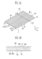
- FIG. 2A is a top-side perspective view of an embodiment of a light guide member employing one or more aspects of the invention
- FIG. 2B is a cross-sectional view of the exemplary light guide member illustrated in FIG. 2A, taken along line A-A' of FIG. 2A;
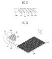
- FIG. 2C is a cross-sectional view of the exemplary light guide member illustrated in FIG.2A, taken along the line B-B' of FIG. 2A;
- FIG. 2D is a bottom-side view of the exemplary light guide member illustrated in FIG. 2A, as viewed from a direction of arrow C of FIG. 2A;
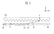
- FIG. 3 illustrates a general cross-sectional view of an exemplary light guide member and an optical member employing one or more aspects of the invention.
- FIG. 1 illustrates an exploded perspective view of parts of an liquid crystal display (LCD) device, as an device, employing an exemplary embodiment of a backlight and an exemplary embodiment of a light guiding member according to one or more aspects of the invention.
- LCD liquid crystal display
- a LCD device includes a LCD panel 100 and a backlight unit (BLU) 130.
- the BLU 130 serves to provide light to the LCD panel 100 such that images can be displayed on the LCD panel 100.
- the LCD panel 100 includes two substrates disposed opposite each other, a liquid crystal layer provided between the two substrates, and a pixel region (not shown) defined by, e.g., a plurality of gate lines and data lines arranged on the substrates in, e.g., a matrix-type manner.
- a thin film transistor and a pixel electrode are formed at respective portions of one of the substrates corresponding to intersecting portions of the gate lines and data lines formed thereon (not shown).
- Each pixel electrode is connected to the respective thin film transistor, and each thin film transistor controls signals respectively supplied to the respective pixel(s).
- a color filter (not shown) and a common electrode (not shown) are formed on the other of the substrates.
- a polarizing film (not shown) are provided on an outer side of each of the substrates.
- the BLU 130 includes a light guide member 131, a light source unit 132, an optical member 134, and a reflective member 133.
- the first side 151 of the light guide member is reflective in this embodiment, and is arranged to face the reflective member 133 of the BLU 130.
- a second side 152 is an exit side, of the light guide member 131 and is arranged to face the optical member 134.
- the light source unit 132 supplies light to the light guide member 131.
- the light guide member 131 is arranged to change a distribution of light provided from the light source unit 132.
- the reflective member 133 reflects light back toward the LCD panel 100.
- the light guide member 131 changes a distribution of light received, from one or more light sources 132a of the light source unit 132. More particularly, the light guide member 131 changes a distribution of light concentrated on a plurality of small areas thereof, and can, thereby, provide uniform and/or substantially uniform light over a relatively larger area corresponding to the plurality of small areas and/or an entire area of, e.g., the second side 152 of the light guide member 131.
- light guide member 131 has a thin-plate-like cuboid shape. Other embodiments may employ different shapes.
- the light guide member 131 of this embodiment includes, transparent resin such, e.g., acryl or polycarbonate, etc.
- the light guide member 131 includes a first side 151, a second side 152, a first end surface 153, and a second end surface 154.
- the first side 151 and the second side 152 oppose each other, and the first end surface 153 and the second end surface 154 oppose each other. More particularly, the first end surface 153 and the second end surface 154 extend between and connect respective edge portions of the first side 151 and the second side 152 together.
- the light source unit 132 is disposed on one or more sides, of the light guide member 131.
- a point light source such as a light emitting diode (LED) light-emitting white light
- LED light emitting diode
- the light source 132a may be, e.g., a cold cathode fluorescent lamp (CCFL) and/or an LED.
- CCFLs may generally be employed for larger-sized display devices, and LEDs may generally be employed for smaller-sized display devices.
- the light sources 132a are arranged on a single side, i.e., adjacent the first end surface 153, of the light guide member 131. That is, in this embodiment of the invention, the light guide member 131 only receives light from one side, e.g., the first end surface 153 of the light guide member 131.
- other embodiments of the invention are not limited to such an arrangement.
- the optical member 134 collects and reflects the light having a uniform luminance distribution, so as to help enhance brightness of the display device and/or only allow light with a predetermined incident angle to pass through.
- the optical member 134 includes a prism sheet that only allows substantially vertical direction, e.g., z-direction, light to pass therethrough, while light having other incident angles is reflected toward the reflective member 133 before being reflected back again toward the optical member 134, until the light vertically passes through the optical member 134 toward the LCD panel 100.
- the optical member 134 includes a prism sheet. In some embodiments of the invention, the optical member 134 only includes a prism sheet. In other embodiments of the invention, the optical member 134 may include more than a single prism sheet, but does not include a diffusion sheet. Referring to FIG. 1, the optical member 134 includes one or more grooves 135 formed on a side 139 facing the light guide member 131. The prism sheet of the optical member 134 helps improve the vertical incident capability by diffusing and collecting light incident from the light guide member 131 in a direction of the LCD panel 100.
- the light guide member includes first grooves 136, second grooves 137 and third grooves 138 in this embodiment. Other embodiments may only include first grooves 136 and second grooves 137.
- a plurality of the first grooves 136 are formed on the second side 152 of the light guide member 131.
- the first grooves 136 extend, along a second direction, e.g., y-direction, which in this case is parallel to a zero-degree radiation angle of light emitted from the light sources 132a.
- FIG. 2A illustrates a top-side perspective view of an embodiment of a light guide member employing one or more aspects of the invention.
- FIG. 2B illustrates a cross-sectional view of the exemplary light guide member illustrated in FIG. 2A, taken along line A-A' of FIG. 2A.
- FIG. 2C illustrates a cross-sectional view of the light guide member illustrated in FIG. 2A, taken along the line B-B' of FIG. 2A
- FIG. 2D illustrates a bottom-side view of the light guide member illustrated in FIG. 2A, as viewed from a direction of arrow C of FIG. 2A including an enlarged view of a circled portion of the exemplary light guide member as illustrated in FIG. 2D.
- the second grooves 137 extend along a first direction, e.g., x-direction, on the first side 151 of the light guide member 131.
- the first direction in this embodiment is substantially perpendicular to a zero-degree radiation angle of light emitted from the light source(s) 132a.
- the third grooves 138 extend along the second direction, e.g., y-direction, on the first side 151 of the light guide member 131.
- the second direction is substantially parallel to the zero-degree radiation angle of light emitted from the light source(s) 132a and is substantially perpendicular to the first direction, e.g., x-direction.
- first grooves 136 and the second grooves 137 extend along directions that are substantially orthogonal to each other, and the first grooves 136 and the third grooves 138 extend along directions that are substantially parallel to each other.
- first grooves 136 and the third grooves 138 extend along directions that are substantially parallel to each other.
- the first grooves 136, the second grooves 137 and the third grooves 138 are substantially V- shaped grooves. More particularly, in embodiments of the invention, irrespective of a depth and/or a width of the first grooves 136, the second grooves 137 and the third grooves 138, a cross-sectional shape of the first grooves 136, the second grooves 137 and the third grooves 138 is substantially V-shaped, as taken along a line extending along the second direction and/or along the first direction, respectively. Embodiments of the invention are not limited to such structures.
- first grooves 136 may be formed on the second side 152 of the light guide member 131, and the second grooves 137 and the third grooves 138 may be formed on the first side 151 of the light guide member 131. It is also the case that embodiments of the invention are not limited to the specific proportions of he grooves shown herein and the depth and width of the grooves may be varied to suit needs.
- a vertical angle ⁇ 1 formed by inner sides 136a, 136b first grooves 136 is about 85° to about 120° in some embodiments of the invention.
- the vertical angle ⁇ 1 of the first grooves 136 plays an important role in the uniformity of the luminance distribution of light provided by the light guide member 131, and thereby, plays an important role in the image quality of image(s) displayed on a display panel.
- the vertical angle ⁇ 1 of the first grooves 136 is less than about 85°, directional uniformity of the light can be easily controlled. However, in such cases, bright lines/areas and/or dark areas can be produced, and a luminance distribution may be hindered.
- the vertical angle ⁇ 1 of the first grooves 136 is greater than about 120°, the luminance distribution of the light can be substantially and/or completely uniform. However, in such cases, the directional uniformity of the light may be difficult to control.
- a cross-sectional shape of the first grooves 136 taken along a line extending, e.g., along the second direction, is an isosceles triangle, and the first grooves 136 are arranged at regular intervals.
- a vertical angle ⁇ 2 formed by inner sides 137a, 137b of the second grooves 137 is about 130° to about 150° in some embodiments of the invention.
- An angle ⁇ 3 formed by one of the inner sides, i.e., 137a, which is closer to the third side 153, and a plane extending along the x and y directions, e.g., x-y plane, may be about 1° to about 3°. That is, the angle ⁇ 3 corresponds to the angle between the inner side, e.g., 137a, of the second groove closer to the light source 132a.
- the inner side, i.e., 137a, forming the angle ⁇ 3 relative to the x-y plane may have a length that is longer than a length of the other of the inner sides, i.e., 137b.
- the second grooves 137 are arranged at regular intervals in this embodiment. Embodiments of the invention are not limited to a particular depth, width and pitch of the second grooves 137.
- a vertical angle ⁇ 4 formed by two inner sides 138a, 138b of the third grooves 138 is about 120° to about 160° in some embodiments of the invention.
- a cross-sectional shape of the third grooves 138, taken along a line extending, e.g., along the first direction, is an isosceles triangle.
- the third grooves 138 have substantially a same depth, width and/or pitch as the first grooves 136.
- embodiments of the invention are not limited to such structures. That is, in some embodiments of the invention, the third grooves 138 may have a different depth, width and/or pitch relative to a depth, width and/or pitch of the first grooves 136.
- Table 1 provides depth, width, pitch and vertical angle values for each of exemplary first grooves 136, second grooves 137 and third grooves 138 for this embodiment of a light guide member.
- Table I only provides exemplary values, and embodiments of the invention are not limited to the exemplary values provided therein.
- the second grooves 137 intersect the third grooves 138 and form a matrix like pattern with a plurality of cell-like portions on the first side 151 of the light guide member 131.
- a projecting polygonal-like pattern which in this embodiment is a pyramid-like pattern 160, is formed at each of the cell-like portions on the first side 151 of the light guide member 131.
- the pyramid-like patterns 160 have a pointed edge 161 corresponding to a meeting of outer edges of the second and third grooves 137, 138. Adjacent ones of the pyramid-like patterns 160 share common boundary portions corresponding to respective base portions of the second grooves 137 and third grooves 138.
- adjacent ones of the pyramid-like patterns 160 along the first direction e.g., x-direction
- adjacent ones of the pyramid-like patterns 160 along the second direction e.g., y-direction
- Other embodiments may employ other matrix like patterns, and the embodiments of the present invention are not limited to the exemplary projecting polygonal-like pattern shown in Figure 2D.
- FIG. 3 illustrates a general cross-sectional view of an exemplary light guide member and an optical member employing one or more aspects of the invention.
- An exemplary operation of the light guide member 131 is described below with reference to FIGS. 2 and 3.
- Light is emitted from the light source unit 132 towards the light guide member 131. More specifically, light from the light source unit 132 is emitted toward the first side 151 of the light guide member 131. The light from the light source unit 132 is then completely or substantially completely reflected and guided to the LCD panel 100 via the light guide member 131 employing one or more aspects of the invention. If the incident light has an angle greater than a predetermined critical angle, the incident light may exit via the first side 151 of the light guide member 131.
- an exit angle E1 of the light from the second side 152 of the light guide member 131 is about 74° to about 76° relative to a plane extending along the first and second directions, e.g., x-y plane.
- the second side 152 of the light guide member 131 faces an optical member 134, which in some embodiments includes, e.g., an inverse prism sheet.
- an exit angle of the light output from the light guide member 131 is about 74% to about 76% relative to, e.g., the x-y plane
- light can exit from the optical member 134, e.g., inverse prism sheet, at an exit angle of about 0° to about 2° relative to a third direction, e.g., z-direction.
- the third direction is substantially perpendicular to the first and second directions in this embodiment.
- the exit angle E1 of light of the light depends on an incidence angle ⁇ .
- the vertical angle ⁇ 2 formed by two inner sides 137a, 137b can be about 130° to about 150°
- the angle ⁇ 3 formed by one of the inner sides, i.e., 137a, which is closer to the third side 153, and a plane extending along the x and y directions, e.g., x-y plane can be about 1° to about 3°. That is, the angle ⁇ 3 corresponds to the angle between the inner side, e.g., 137a, of the second groove 137 closer to the light source 132a.
- the incidence angle ⁇ ' may be increased to ⁇ +N* ⁇ 3.
- each time the incident light is reflected the incidence angle is increased by ⁇ 3, and when the incidence angle is larger than the predetermined critical angle, the incidence light exits from the second side 152 of the light guide member 131 with a certain angle.
- the shape of the third grooves 138 and the shape of the second grooves 137 helps concentrate light incident thereon, and helps reduce spreading of the light to help the luminance distribution of light output from the light guide member 131.
- embodiments of the invention can provide light guide member(s) capable of outputting light having a substantially uniform and/or completely uniform luminance distribution and a substantially uniform and/or completely uniform direction.
- bright areas/lines and/or dark areas on the luminance distribution of light emitted from light guide members employing one or more aspects of the invention may be reduced and/or prevented.
- Table 2 compares a luminance distribution of a conventional BLU with a luminance distribution of a backlight unit including a light guide member employing one or more aspects of the invention.
- Table 2 Luminance Increasing rate of the luminance Conventional BLU 5,698cd/m 2 1
- the conventional BLU includes a light guide member with conventional diffusive patterns formed thereon, two prism sheets and diffusing sheets.
- the BLU employing one or more aspects of the invention employs a light guide member including intersecting grooves, e.g., second and third grooves 137, 138, on one side thereof, and an optical member including only a prism sheet.
- the luminance of the light guide member according to the embodiment of the invention is higher than that of the conventional light guide member.
- light guide member(s) and BLUs employing one or more aspects of the invention enable light having a more uniform and/or completely uniform luminance distribution and more uniform and/or completely uniform directionality to be output from the light guide member.
- light guide members and BLUs including, e.g., intersecting grooves forming pyramid-like patterns on a same side of the light guide member, the luminance distribution and directional uniformity of the light emitted from the light guide member can be improved relative to conventional light guide members and BLUs.
- embodiments of the invention may help improve brightness of the display by maximizing the reflective characteristics of light incident on the light guide member.
- Embodiments of the invention separately enable lighter, thinner and/or smaller sized BLUs relative to conventional BLUs by, e.g., reducing and/or eliminating a need for diffusion sheets in an optical member of the BLU.
- embodiments of the light guide member and the backlight unit can be described in relation to an exemplary LCD device, embodiments of the invention are not limited to use with an LCD device. Further, although reference is made to a "backlight unit” as an exemplary illumination device, such units are generally called “backlight” units because they may be arranged behind the display panel. However, aspects of the invention are not limited to such arrangements and/or uses.
Landscapes
- Physics & Mathematics (AREA)
- General Physics & Mathematics (AREA)
- Optics & Photonics (AREA)
- Nonlinear Science (AREA)
- Mathematical Physics (AREA)
- Chemical & Material Sciences (AREA)
- Crystallography & Structural Chemistry (AREA)
- Planar Illumination Modules (AREA)
- Liquid Crystal (AREA)
Abstract
a plurality of second grooves extending along a second direction on the first side of the light guide member, the first direction may cross the second direction such that the first grooves and the second grooves may form a matrix pattern on the first side of the light guide member, wherein a polygonal shaped projection is formed between every two adjacent ones of the second grooves and a corresponding two adjacent ones of the first grooves.
Description
- The invention relates to a light guide member and a backlight unit including a light guide member. More particularly, the invention relates to a light guide member for guiding light traveling therein and providing uniformly distributed light, and a backlight unit employing such a light guide member.
- A light guide member may be employed, by an illumination device of a display device, to receive light from a light source of the illumination device, and guide the received light so as to provide light having a uniform luminance distribution to a display panel of the display device. For example, a flat panel display device, e.g., a liquid crystal display (LCD), may include an illumination device, e.g., a backlight unit (BLU) including a light guide member.
- There is a demand for improved display devices in, e.g., the information and communication industries. More particularly, e.g., higher resolution, lighter, thinner, and/or less power consuming display devices are desired. One possible approach for developing such improved display devices is to provide thinner, lighter BLUs and/or improved light guide members capable of providing light having a more uniform luminance distribution.
- For example, one type of flat panel display that is widely used today is thin film transistor-liquid crystal displays (TFT-LCDs). Such TFT-LCDs may include a LCD panel in which liquid crystal is provided between two substrates, a BLU as an illumination device positioned in a lower portion of the LCD panel, and a LCD drive IC (LDI) for driving the LCD panel. The BLU unit may include, e.g., a light source, a light guide member, and an optical sheet including a diffusion sheet and a prism sheet.
- The light source may supply non-uniformly distributed linear light to the light guide member. Generally, the light guide member is to modify the non-uniformly distributed linear light and output planar light having a uniform optical distribution. However, conventional light guide members fall short of outputting uniformly distributed linear light. For example, portions of the light guide member arranged between, and in close proximity to, light sources of the illumination device may provide less light, i.e., appear darker, than portions of the light guide member arranged substantially along a zero-degree radiation angle of the respective light source.
- More particularly, in general, as the radiation angle of light from the light source increases, an intensity of the radiated light decreases. The diffusion of light is also generally weak at a portion of a light guide member close to the light source. Thus, at portions of the light guide member receiving light from the light source via relatively larger radiation angles and/or beyond a radiation angle of the light, the intensity of light output from the light guide member may not have a uniform luminance distribution. As a result of such non-uniformity, a luminance distribution of light from the light guide member may include a bright line, bright area and/or dark area, e.g., close to the light source, i.e., a bright line/area effect. Such a bright line/area effect may be particularly prominent at portions of the light guide member that do not overlap with or are not aligned with light sources of a light source unit. When, light having a non-uniform luminance distribution is provided to a display device, image quality of the display device may be hindered.
- In view of such shortcomings of the light guide member, a BLU employing such light guide members may include a plurality of optical sheets, e.g., a diffusion sheet and a prism sheet, in an attempt to provide light having a more uniformly distributed luminance to the display device. However, having to provide additional optical sheets may increase the cost, weight and/or size of the BLU.
- It is an object of the invention to provide a light guide member and a backlight unit including such a light guide member, which substantially overcome one or more of the problems due to limitations and disadvantages of the related art.
- It is therefore a feature of embodiments of the invention to provide a light guide member capable of guiding light to output light having a more uniform luminance distribution relative to conventional light guide members.
- It is therefore a separate feature of embodiments of the invention to provide a BLU employing only a prism sheet as an optical member.
- It is therefore a separate feature of embodiments of the invention to provide a light guide member capable of guiding light to output light having an entirely uniform luminous distribution.
- It is therefore a separate feature of embodiments of the invention to provide a thinner and/or lighter BLU.
- According to a first aspect of the invention, there is provided a light guide member as set out in Claim 1. Preferred features of this aspect are set out in
Claims 2 to 14. According to a second aspect of the invention, there is provided a backlight unit as set out in Claim 15. Preferred features of this aspect are set out in Claims 16 to 18. - The above and other features and advantages of the invention will become more apparent to those of ordinary skill in the art by describing in detail exemplary embodiments thereof with reference to the attached drawings in which:
- FIG. 1 is an exploded perspective view of parts of an liquid crystal display (LCD) device, as an device, employing an embodiment of a backlight and an exemplary embodiment of a light guiding member according to one or more aspects of the invention;
- FIG. 2A is a top-side perspective view of an embodiment of a light guide member employing one or more aspects of the invention;
- FIG. 2B is a cross-sectional view of the exemplary light guide member illustrated in FIG. 2A, taken along line A-A' of FIG. 2A;
- FIG. 2C is a cross-sectional view of the exemplary light guide member illustrated in FIG.2A, taken along the line B-B' of FIG. 2A;
- FIG. 2D is a bottom-side view of the exemplary light guide member illustrated in FIG. 2A, as viewed from a direction of arrow C of FIG. 2A; and
- FIG. 3 illustrates a general cross-sectional view of an exemplary light guide member and an optical member employing one or more aspects of the invention.
- The invention will now be described more fully hereinafter with reference to the accompanying drawings, in which exemplary embodiments of the invention are illustrated. The invention may, however, be embodied in different forms and should not be construed as limited to the embodiments set forth herein. Rather, these embodiments are provided so that this disclosure will be thorough and complete, and will fully convey the scope of the invention to those skilled in the art.
- In the figures, the dimensions of layers and regions may be exaggerated for clarity of illustration. It will also be understood that when an element is referred to as being "on" another element, it can be directly on the other element, or intervening elements may also be present. Further, it will be understood that when an element is referred to as being "under" another element, it can be directly under, and one or more intervening elements may also be present. In addition, it will also be understood that when an element is referred to as being "between" two elements, it can be the only element between the two elements, or one or more intervening elements may also be present. Like reference numerals refer to like elements throughout. In the following description, references made to "first," "second," etc. merely serve to identify different elements and/or features of different elements and, unless specified otherwise, the features may or may not have the same values.
- FIG. 1 illustrates an exploded perspective view of parts of an liquid crystal display (LCD) device, as an device, employing an exemplary embodiment of a backlight and an exemplary embodiment of a light guiding member according to one or more aspects of the invention.
- Referring to FIG. 1, a LCD device includes a
LCD panel 100 and a backlight unit (BLU) 130. TheBLU 130 serves to provide light to theLCD panel 100 such that images can be displayed on theLCD panel 100. - The
LCD panel 100 includes two substrates disposed opposite each other, a liquid crystal layer provided between the two substrates, and a pixel region (not shown) defined by, e.g., a plurality of gate lines and data lines arranged on the substrates in, e.g., a matrix-type manner. A thin film transistor and a pixel electrode are formed at respective portions of one of the substrates corresponding to intersecting portions of the gate lines and data lines formed thereon (not shown). Each pixel electrode is connected to the respective thin film transistor, and each thin film transistor controls signals respectively supplied to the respective pixel(s). A color filter (not shown) and a common electrode (not shown) are formed on the other of the substrates. A polarizing film (not shown) are provided on an outer side of each of the substrates. - The
BLU 130 includes alight guide member 131, alight source unit 132, anoptical member 134, and areflective member 133. Thefirst side 151 of the light guide member, is reflective in this embodiment, and is arranged to face thereflective member 133 of theBLU 130. A second side 152is an exit side, of thelight guide member 131 and is arranged to face theoptical member 134. Thelight source unit 132 supplies light to thelight guide member 131. Thelight guide member 131 is arranged to change a distribution of light provided from thelight source unit 132. Thereflective member 133 reflects light back toward theLCD panel 100. - The
light guide member 131 changes a distribution of light received, from one or morelight sources 132a of thelight source unit 132. More particularly, thelight guide member 131 changes a distribution of light concentrated on a plurality of small areas thereof, and can, thereby, provide uniform and/or substantially uniform light over a relatively larger area corresponding to the plurality of small areas and/or an entire area of, e.g., thesecond side 152 of thelight guide member 131. - In this embodiment
light guide member 131 has a thin-plate-like cuboid shape. Other embodiments may employ different shapes. Thelight guide member 131 of this embodiment includes, transparent resin such, e.g., acryl or polycarbonate, etc. - The
light guide member 131 includes afirst side 151, asecond side 152, afirst end surface 153, and asecond end surface 154. Thefirst side 151 and thesecond side 152 oppose each other, and thefirst end surface 153 and thesecond end surface 154 oppose each other. More particularly, thefirst end surface 153 and thesecond end surface 154 extend between and connect respective edge portions of thefirst side 151 and thesecond side 152 together. - The
light source unit 132 is disposed on one or more sides, of thelight guide member 131. A point light source, such as a light emitting diode (LED) light-emitting white light, may be used as thelight source 132a, and one or morelight sources 132a may be arranged depending on, e.g., a size of thelight guide member 131. Alternatively or additionally, thelight source 132a may be, e.g., a cold cathode fluorescent lamp (CCFL) and/or an LED. CCFLs may generally be employed for larger-sized display devices, and LEDs may generally be employed for smaller-sized display devices. - In the embodiment illustrated in FIG. 1, the
light sources 132a are arranged on a single side, i.e., adjacent thefirst end surface 153, of thelight guide member 131. That is, in this embodiment of the invention, thelight guide member 131 only receives light from one side, e.g., thefirst end surface 153 of thelight guide member 131. However, other embodiments of the invention are not limited to such an arrangement. - The
optical member 134 collects and reflects the light having a uniform luminance distribution, so as to help enhance brightness of the display device and/or only allow light with a predetermined incident angle to pass through. In this particular case, theoptical member 134 includes a prism sheet that only allows substantially vertical direction, e.g., z-direction, light to pass therethrough, while light having other incident angles is reflected toward thereflective member 133 before being reflected back again toward theoptical member 134, until the light vertically passes through theoptical member 134 toward theLCD panel 100. - The
optical member 134 includes a prism sheet. In some embodiments of the invention, theoptical member 134 only includes a prism sheet. In other embodiments of the invention, theoptical member 134 may include more than a single prism sheet, but does not include a diffusion sheet. Referring to FIG. 1, theoptical member 134 includes one ormore grooves 135 formed on aside 139 facing thelight guide member 131. The prism sheet of theoptical member 134 helps improve the vertical incident capability by diffusing and collecting light incident from thelight guide member 131 in a direction of theLCD panel 100. - The light guide member includes
first grooves 136,second grooves 137 andthird grooves 138 in this embodiment. Other embodiments may only includefirst grooves 136 andsecond grooves 137. Referring to FIG. 1 in the first embodiment of thelight guide member 131 employing one or more aspects of the invention, a plurality of thefirst grooves 136 are formed on thesecond side 152 of thelight guide member 131. Thefirst grooves 136 extend, along a second direction, e.g., y-direction, which in this case is parallel to a zero-degree radiation angle of light emitted from thelight sources 132a. - FIG. 2A illustrates a top-side perspective view of an embodiment of a light guide member employing one or more aspects of the invention. FIG. 2B illustrates a cross-sectional view of the exemplary light guide member illustrated in FIG. 2A, taken along line A-A' of FIG. 2A. FIG. 2C illustrates a cross-sectional view of the light guide member illustrated in FIG. 2A, taken along the line B-B' of FIG. 2A, and FIG. 2D illustrates a bottom-side view of the light guide member illustrated in FIG. 2A, as viewed from a direction of arrow C of FIG. 2A including an enlarged view of a circled portion of the exemplary light guide member as illustrated in FIG. 2D.
- Referring to FIGS. 2A to 2D, the
second grooves 137 extend along a first direction, e.g., x-direction, on thefirst side 151 of thelight guide member 131. The first direction in this embodiment is substantially perpendicular to a zero-degree radiation angle of light emitted from the light source(s) 132a. Thethird grooves 138 extend along the second direction, e.g., y-direction, on thefirst side 151 of thelight guide member 131. In this embodiment, the second direction is substantially parallel to the zero-degree radiation angle of light emitted from the light source(s) 132a and is substantially perpendicular to the first direction, e.g., x-direction. Therefore, in this embodiment,first grooves 136 and thesecond grooves 137 extend along directions that are substantially orthogonal to each other, and thefirst grooves 136 and thethird grooves 138 extend along directions that are substantially parallel to each other. When light is provided to one or more sides, e.g., thefirst end surface 153, of thelight guide member 131, an optical path and distribution of the received light is changed by the first, second andthird grooves third grooves - The
first grooves 136, thesecond grooves 137 and thethird grooves 138 are substantially V- shaped grooves. More particularly, in embodiments of the invention, irrespective of a depth and/or a width of thefirst grooves 136, thesecond grooves 137 and thethird grooves 138, a cross-sectional shape of thefirst grooves 136, thesecond grooves 137 and thethird grooves 138 is substantially V-shaped, as taken along a line extending along the second direction and/or along the first direction, respectively. Embodiments of the invention are not limited to such structures. For example, in other embodiments thefirst grooves 136 may be formed on thesecond side 152 of thelight guide member 131, and thesecond grooves 137 and thethird grooves 138 may be formed on thefirst side 151 of thelight guide member 131. It is also the case that embodiments of the invention are not limited to the specific proportions of he grooves shown herein and the depth and width of the grooves may be varied to suit needs. - Referring to FIG. 2B, a vertical angle θ1 formed by
inner sides first grooves 136 is about 85° to about 120° in some embodiments of the invention. The vertical angle θ1 of thefirst grooves 136 plays an important role in the uniformity of the luminance distribution of light provided by thelight guide member 131, and thereby, plays an important role in the image quality of image(s) displayed on a display panel. When the vertical angle θ1 of thefirst grooves 136 is less than about 85°, directional uniformity of the light can be easily controlled. However, in such cases, bright lines/areas and/or dark areas can be produced, and a luminance distribution may be hindered. When the vertical angle θ1 of thefirst grooves 136 is greater than about 120°, the luminance distribution of the light can be substantially and/or completely uniform. However, in such cases, the directional uniformity of the light may be difficult to control. - In some embodiments of the invention, a cross-sectional shape of the
first grooves 136, taken along a line extending, e.g., along the second direction, is an isosceles triangle, and thefirst grooves 136 are arranged at regular intervals. - Referring to FIG. 2C, a vertical angle θ2 formed by
inner sides second grooves 137 is about 130° to about 150° in some embodiments of the invention. An angle θ3 formed by one of the inner sides, i.e., 137a, which is closer to thethird side 153, and a plane extending along the x and y directions, e.g., x-y plane, may be about 1° to about 3°. That is, the angle θ3 corresponds to the angle between the inner side, e.g., 137a, of the second groove closer to thelight source 132a. In some embodiments of the invention, the inner side, i.e., 137a, forming the angle θ3 relative to the x-y plane may have a length that is longer than a length of the other of the inner sides, i.e., 137b. Thesecond grooves 137 are arranged at regular intervals in this embodiment. Embodiments of the invention are not limited to a particular depth, width and pitch of thesecond grooves 137. - Referring to FIG. 2B, a vertical angle θ4 formed by two
inner sides third grooves 138 is about 120° to about 160° in some embodiments of the invention. In some embodiments of the invention, a cross-sectional shape of thethird grooves 138, taken along a line extending, e.g., along the first direction, is an isosceles triangle. In some embodiments of the invention, thethird grooves 138 have substantially a same depth, width and/or pitch as thefirst grooves 136. However, embodiments of the invention are not limited to such structures. That is, in some embodiments of the invention, thethird grooves 138 may have a different depth, width and/or pitch relative to a depth, width and/or pitch of thefirst grooves 136. - Table 1 provides depth, width, pitch and vertical angle values for each of exemplary
first grooves 136,second grooves 137 andthird grooves 138 for this embodiment of a light guide member. Table I only provides exemplary values, and embodiments of the invention are not limited to the exemplary values provided therein.Table 1 First Grooves Second Grooves Third Grooves Depth (µm) 7.67 4 6 Width (µm) 20 121.5 68.5 Pitch (µm) 30 121.5 68 Angle (°) 105 148 160 - Referring to FIG. 2D, in this embodiment the
second grooves 137 intersect thethird grooves 138 and form a matrix like pattern with a plurality of cell-like portions on thefirst side 151 of thelight guide member 131. A projecting polygonal-like pattern, which in this embodiment is a pyramid-like pattern 160, is formed at each of the cell-like portions on thefirst side 151 of thelight guide member 131. In this embodiment of the invention, the pyramid-like patterns 160 have a pointededge 161 corresponding to a meeting of outer edges of the second andthird grooves like patterns 160 share common boundary portions corresponding to respective base portions of thesecond grooves 137 andthird grooves 138. For example, adjacent ones of the pyramid-like patterns 160 along the first direction, e.g., x-direction, share a common boundary portion corresponding to abase 140 of thesecond grooves 137, and adjacent ones of the pyramid-like patterns 160 along the second direction, e.g., y-direction, share a common boundary portion corresponding to abase 141 of thethird grooves 138. Other embodiments may employ other matrix like patterns, and the embodiments of the present invention are not limited to the exemplary projecting polygonal-like pattern shown in Figure 2D. - FIG. 3 illustrates a general cross-sectional view of an exemplary light guide member and an optical member employing one or more aspects of the invention. An exemplary operation of the
light guide member 131 is described below with reference to FIGS. 2 and 3. Light is emitted from thelight source unit 132 towards thelight guide member 131. More specifically, light from thelight source unit 132 is emitted toward thefirst side 151 of thelight guide member 131. The light from thelight source unit 132 is then completely or substantially completely reflected and guided to theLCD panel 100 via thelight guide member 131 employing one or more aspects of the invention. If the incident light has an angle greater than a predetermined critical angle, the incident light may exit via thefirst side 151 of thelight guide member 131. - In some embodiments of the invention, an exit angle E1 of the light from the
second side 152 of thelight guide member 131 is about 74° to about 76° relative to a plane extending along the first and second directions, e.g., x-y plane. As illustrated in FIGS. 2 and 3, thesecond side 152 of thelight guide member 131 faces anoptical member 134, which in some embodiments includes, e.g., an inverse prism sheet. When an exit angle of the light output from thelight guide member 131 is about 74% to about 76% relative to, e.g., the x-y plane, light can exit from theoptical member 134, e.g., inverse prism sheet, at an exit angle of about 0° to about 2° relative to a third direction, e.g., z-direction. The third direction is substantially perpendicular to the first and second directions in this embodiment. Referring to FIG. 3, the exit angle E1 of light of the light depends on an incidence angle β. - As discussed above, in some embodiments of the invention, the vertical angle θ2 formed by two
inner sides third side 153, and a plane extending along the x and y directions, e.g., x-y plane, can be about 1° to about 3°. That is, the angle θ3 corresponds to the angle between the inner side, e.g., 137a, of thesecond groove 137 closer to thelight source 132a. As a result, when light incident on thelight guide member 131 is reflected by thefirst side 151 for the Nth time, the incidence angle β' may be increased to β+N* θ3. - Thus, in embodiments of the invention, each time the incident light is reflected, the incidence angle is increased by θ3, and when the incidence angle is larger than the predetermined critical angle, the incidence light exits from the
second side 152 of thelight guide member 131 with a certain angle. - In some embodiments of the invention, the shape of the
third grooves 138 and the shape of thesecond grooves 137 helps concentrate light incident thereon, and helps reduce spreading of the light to help the luminance distribution of light output from thelight guide member 131. As a result, embodiments of the invention can provide light guide member(s) capable of outputting light having a substantially uniform and/or completely uniform luminance distribution and a substantially uniform and/or completely uniform direction. Thus, bright areas/lines and/or dark areas on the luminance distribution of light emitted from light guide members employing one or more aspects of the invention may be reduced and/or prevented. - Table 2 compares a luminance distribution of a conventional BLU with a luminance distribution of a backlight unit including a light guide member employing one or more aspects of the invention.
Table 2 Luminance Increasing rate of the luminance Conventional BLU 5,698cd/m2 1 Exemplary BLU including light guide member employing one or more aspects of the invention. 10,000~11,000cd/m2 1.75~1.92 - In the comparative example above, the conventional BLU includes a light guide member with conventional diffusive patterns formed thereon, two prism sheets and diffusing sheets. The BLU employing one or more aspects of the invention employs a light guide member including intersecting grooves, e.g., second and
third grooves - In accordance with Table 2, the luminance of the light guide member according to the embodiment of the invention is higher than that of the conventional light guide member.
- Aspects of the invention are described above with reference to exemplary embodiments, however, modifications and variations thereof may be made without departing from the spirit and scope of the invention. For example, the angle of each pattern, depth of the pattern, width can be changed. Furthermore, persons skilled in the art appreciate that the various modifications and changes of the constitution of the backlight unit comprising the light guide member described with the embodiment of the invention can be made.
- As described above, light guide member(s) and BLUs employing one or more aspects of the invention enable light having a more uniform and/or completely uniform luminance distribution and more uniform and/or completely uniform directionality to be output from the light guide member. By providing light guide members and BLUs including, e.g., intersecting grooves forming pyramid-like patterns on a same side of the light guide member, the luminance distribution and directional uniformity of the light emitted from the light guide member can be improved relative to conventional light guide members and BLUs. Thus, e.g., when light guide members are employed in display device, embodiments of the invention may help improve brightness of the display by maximizing the reflective characteristics of light incident on the light guide member.
- Embodiments of the invention separately enable lighter, thinner and/or smaller sized BLUs relative to conventional BLUs by, e.g., reducing and/or eliminating a need for diffusion sheets in an optical member of the BLU.
- Although embodiments of the light guide member and the backlight unit can be described in relation to an exemplary LCD device, embodiments of the invention are not limited to use with an LCD device. Further, although reference is made to a "backlight unit" as an exemplary illumination device, such units are generally called "backlight" units because they may be arranged behind the display panel. However, aspects of the invention are not limited to such arrangements and/or uses.
- Exemplary embodiments of the invention have been disclosed herein, and although specific terms are employed, they are used and are to be interpreted in a generic and descriptive sense only and not for purpose of limitation. For example, while V-grooves have been illustrated in embodiments of the invention, an angle formed between the light and the wave pattern may be more important than the shape of the groove itself. While a V-groove may be the most efficient manner to realize the appropriate wave pattern, the groove may, e.g., be curved or have a flat base, rather a V shape. Accordingly, it will be understood by those of ordinary skill in the art that various changes in form and details may be made without departing from the scope of the invention as set forth in the following claims.
Claims (17)
Applications Claiming Priority (1)
| Application Number | Priority Date | Filing Date | Title |
|---|---|---|---|
| KR1020060062727A KR100830340B1 (en) | 2006-07-04 | 2006-07-04 | Light guide plate of backlight unit and backlight unit having same |
Publications (2)
| Publication Number | Publication Date |
|---|---|
| EP1876388A1 true EP1876388A1 (en) | 2008-01-09 |
| EP1876388B1 EP1876388B1 (en) | 2011-08-31 |
Family
ID=38564612
Family Applications (1)
| Application Number | Title | Priority Date | Filing Date |
|---|---|---|---|
| EP07252682A Active EP1876388B1 (en) | 2006-07-04 | 2007-07-04 | Light guide member and backlight unit including light guide member |
Country Status (5)
| Country | Link |
|---|---|
| US (1) | US7568827B2 (en) |
| EP (1) | EP1876388B1 (en) |
| JP (1) | JP4545135B2 (en) |
| KR (1) | KR100830340B1 (en) |
| CN (1) | CN101101351B (en) |
Cited By (1)
| Publication number | Priority date | Publication date | Assignee | Title |
|---|---|---|---|---|
| EP1876482B1 (en) * | 2006-07-04 | 2010-12-08 | Samsung Mobile Display Co., Ltd. | Light guide member and backlight unit including the light guide member and methods of fabricating the light guide member and backlight unit |
Families Citing this family (44)
| Publication number | Priority date | Publication date | Assignee | Title |
|---|---|---|---|---|
| CA2752578C (en) | 2003-11-26 | 2016-02-02 | Mckesson Automation Inc. | Integrated suite of medical tools |
| US8087793B2 (en) * | 2007-10-30 | 2012-01-03 | Edward Pakhchyan | Back-light assembly |
| US7568828B2 (en) * | 2007-11-05 | 2009-08-04 | Radiant Opto-Electronics Corp. | Light guide plate with compensated emission light field |
| JP5731112B2 (en) * | 2008-12-03 | 2015-06-10 | パナソニック株式会社 | Light guide plate and display device using the same |
| KR20110050270A (en) | 2009-11-06 | 2011-05-13 | 삼성전자주식회사 | Light Guide Plates, LEDs and Display Devices |
| CN102506386A (en) * | 2011-11-10 | 2012-06-20 | 深圳安嵘光电产品有限公司 | Light guide plate with stereoscopic illuminating effect, method for manufacturing light guide plate, and illuminating lamp |
| TWI539211B (en) | 2012-04-30 | 2016-06-21 | 中強光電股份有限公司 | Light guide plate and backlight module using the same |
| USD681262S1 (en) * | 2012-07-24 | 2013-04-30 | Sang Chul Lee | Light guide plate |
| CN103851540A (en) * | 2012-11-29 | 2014-06-11 | 南京高一智光学科技有限公司 | Light guide plate for backlight module |
| KR102030412B1 (en) * | 2013-05-31 | 2019-10-10 | 엘지디스플레이 주식회사 | Light guide plate having rounded polyggon pattern and liquid cyrstal display device having thereof |
| US10317610B2 (en) * | 2013-12-18 | 2019-06-11 | Sharp Kabushiki Kaisha | Illumination device and display device |
| WO2015098680A1 (en) | 2013-12-24 | 2015-07-02 | シャープ株式会社 | Illumination device and display device |
| US10180527B2 (en) * | 2014-03-19 | 2019-01-15 | Sharp Kabushiki Kaisha | Lighting device and display device |
| US11079619B2 (en) | 2016-05-19 | 2021-08-03 | Reald Spark, Llc | Wide angle imaging directional backlights |
| CN107448909B (en) * | 2016-05-31 | 2019-10-15 | 瑞仪光电(苏州)有限公司 | Backlight Module |
| EP3622342A4 (en) | 2017-05-08 | 2021-02-17 | RealD Spark, LLC | OPTICAL STACKING FOR DIRECTIONAL DISPLAY |
| CN110809732B (en) | 2017-05-08 | 2025-01-10 | 瑞尔D斯帕克有限责任公司 | Optical stack for imaging directional backlights |
| TWI878209B (en) | 2017-09-15 | 2025-04-01 | 美商瑞爾D斯帕克有限責任公司 | Display device and a view angle control optical element for application to a display device |
| US11070791B2 (en) | 2017-11-06 | 2021-07-20 | Reald Spark, Llc | Privacy display apparatus |
| KR20190084545A (en) * | 2018-01-08 | 2019-07-17 | 엘지전자 주식회사 | Display device |
| EP3743766B1 (en) | 2018-01-25 | 2026-02-11 | RealD Spark, LLC | Touch screen for privacy display |
| CN115718382A (en) | 2018-01-25 | 2023-02-28 | 瑞尔D斯帕克有限责任公司 | Reflective optical stack for privacy display device |
| US10935714B2 (en) | 2018-03-22 | 2021-03-02 | Reald Spark, Llc | Optical waveguide for directional backlight |
| US10955715B2 (en) | 2018-06-29 | 2021-03-23 | Reald Spark, Llc | Optical stack for privacy display |
| US11073735B2 (en) | 2018-07-18 | 2021-07-27 | Reald Spark, Llc | Optical stack for switchable directional display |
| WO2020072643A1 (en) | 2018-10-03 | 2020-04-09 | Reald Spark, Llc | Privacy display control apparatus |
| CN113167953B (en) | 2018-11-07 | 2023-10-24 | 瑞尔D斯帕克有限责任公司 | Directional display device |
| US11287677B2 (en) | 2019-01-07 | 2022-03-29 | Reald Spark, Llc | Optical stack for privacy display |
| US11029566B2 (en) | 2019-02-12 | 2021-06-08 | Reald Spark, Llc | Diffuser for privacy display |
| TWI912252B (en) | 2019-07-02 | 2026-01-21 | 美商瑞爾D斯帕克有限責任公司 | Directional display apparatus |
| US11114063B2 (en) | 2019-10-02 | 2021-09-07 | Reald Spark, Llc | Privacy display apparatus |
| CN114846393B (en) | 2019-11-13 | 2024-12-03 | 瑞尔D斯帕克有限责任公司 | Off-axis display device |
| WO2021118936A1 (en) | 2019-12-10 | 2021-06-17 | Reald Spark, Llc | Control of reflections of a display device |
| WO2021222598A1 (en) | 2020-04-30 | 2021-11-04 | Reald Spark, Llc | Directional display apparatus |
| US11353752B2 (en) | 2020-04-30 | 2022-06-07 | Reald Spark, Llc | Directional display apparatus |
| WO2021222615A1 (en) | 2020-04-30 | 2021-11-04 | Reald Spark, Llc | Directional display apparatus |
| EP4189285A4 (en) | 2020-07-29 | 2024-07-24 | RealD Spark, LLC | REAR LIGHTING FOR A SWITCHABLE DIRECTION INDICATOR |
| TWI898003B (en) | 2020-07-29 | 2025-09-21 | 美商瑞爾D斯帕克有限責任公司 | Pupillated illumination apparatus |
| US11892717B2 (en) | 2021-09-30 | 2024-02-06 | Reald Spark, Llc | Marks for privacy display |
| US11977286B2 (en) | 2022-02-09 | 2024-05-07 | Reald Spark, Llc | Observer-tracked privacy display |
| TW202332973A (en) | 2022-02-09 | 2023-08-16 | 美商瑞爾D斯帕克有限責任公司 | Display device with uniform off-axis luminance reduction |
| US11892718B2 (en) | 2022-04-07 | 2024-02-06 | Reald Spark, Llc | Directional display apparatus |
| US12523899B2 (en) | 2023-04-25 | 2026-01-13 | Reald Spark, Llc | Switchable privacy display |
| WO2025030030A2 (en) | 2023-08-03 | 2025-02-06 | Reald Spark, Llc | Privacy displays |
Citations (6)
| Publication number | Priority date | Publication date | Assignee | Title |
|---|---|---|---|---|
| WO2003050448A1 (en) * | 2001-12-05 | 2003-06-19 | Solid State Opto Limited | Transreflectors, transreflector systems and displays and methods of making transreflectors |
| US20030169386A1 (en) * | 2002-03-06 | 2003-09-11 | Sanyo Electric Co., Ltd. | Light guide plate and display device |
| WO2003085428A1 (en) * | 2002-04-05 | 2003-10-16 | Phlox (S.A.) | Backlighting apparatus |
| US20040125592A1 (en) * | 2002-12-06 | 2004-07-01 | Alps Electric Co., Ltd. | Backlight device and liquid crystal display device |
| EP1522881A1 (en) * | 2003-10-06 | 2005-04-13 | Omron Corporation | Surface light source device and display device |
| WO2006054654A1 (en) * | 2004-11-19 | 2006-05-26 | Hitachi Chemical Co., Ltd. | Light guide plate |
Family Cites Families (15)
| Publication number | Priority date | Publication date | Assignee | Title |
|---|---|---|---|---|
| EP0534140B1 (en) * | 1991-08-22 | 1997-07-16 | Tosoh Corporation | Backlighting device |
| JPH07151924A (en) * | 1993-11-30 | 1995-06-16 | Meitaku Syst:Kk | Surface light source |
| JPH08101313A (en) * | 1994-09-30 | 1996-04-16 | Toshiba Lighting & Technol Corp | Backlight and liquid crystal display device using the same |
| JP2950219B2 (en) * | 1995-10-13 | 1999-09-20 | オムロン株式会社 | Surface light source device, image display device using the surface light source device, and prism array used for the surface light source device |
| US6827456B2 (en) * | 1999-02-23 | 2004-12-07 | Solid State Opto Limited | Transreflectors, transreflector systems and displays and methods of making transreflectors |
| JP2001060409A (en) * | 1999-08-23 | 2001-03-06 | Minebea Co Ltd | Planar lighting device |
| JP3363415B2 (en) * | 1999-12-17 | 2003-01-08 | 日本アイ・ビー・エム株式会社 | Reflective liquid crystal display device and reflective unit array |
| KR20010058166A (en) | 1999-12-24 | 2001-07-05 | 박종섭 | Prism sheet for back light unit |
| KR100739527B1 (en) * | 2000-10-13 | 2007-07-13 | 삼성전자주식회사 | Backlight Unit of Liquid Crystal Display |
| JP2003066238A (en) * | 2001-08-27 | 2003-03-05 | Yuka Denshi Co Ltd | Light guide, surface light source device and front light device using the same, and liquid crystal display device |
| JP2004187620A (en) | 2002-12-13 | 2004-07-08 | Sumitomo Pharmaceut Co Ltd | Disease marker for kidney disease and its use |
| JP2005071610A (en) * | 2003-06-26 | 2005-03-17 | Toyota Industries Corp | Light guide plate and surface light source device |
| KR20050007828A (en) | 2003-07-11 | 2005-01-21 | 주식회사 파인옵틱스 | A light guide panel having engraved pyramidal shapes on the bottom surface and the systems thereof, wherein one edge of the pyramidal shape is confroting the side positioned-light source |
| KR20050044961A (en) * | 2003-11-08 | 2005-05-16 | 삼성전자주식회사 | Light guide plate and back light assembly having the same |
| JP4655605B2 (en) * | 2004-12-02 | 2011-03-23 | 日立化成工業株式会社 | Surface light source device and method of assembling surface light source device |
-
2006
- 2006-07-04 KR KR1020060062727A patent/KR100830340B1/en active Active
- 2006-11-17 JP JP2006311693A patent/JP4545135B2/en active Active
-
2007
- 2007-03-23 US US11/727,054 patent/US7568827B2/en active Active
- 2007-07-03 CN CN2007101287066A patent/CN101101351B/en active Active
- 2007-07-04 EP EP07252682A patent/EP1876388B1/en active Active
Patent Citations (6)
| Publication number | Priority date | Publication date | Assignee | Title |
|---|---|---|---|---|
| WO2003050448A1 (en) * | 2001-12-05 | 2003-06-19 | Solid State Opto Limited | Transreflectors, transreflector systems and displays and methods of making transreflectors |
| US20030169386A1 (en) * | 2002-03-06 | 2003-09-11 | Sanyo Electric Co., Ltd. | Light guide plate and display device |
| WO2003085428A1 (en) * | 2002-04-05 | 2003-10-16 | Phlox (S.A.) | Backlighting apparatus |
| US20040125592A1 (en) * | 2002-12-06 | 2004-07-01 | Alps Electric Co., Ltd. | Backlight device and liquid crystal display device |
| EP1522881A1 (en) * | 2003-10-06 | 2005-04-13 | Omron Corporation | Surface light source device and display device |
| WO2006054654A1 (en) * | 2004-11-19 | 2006-05-26 | Hitachi Chemical Co., Ltd. | Light guide plate |
Cited By (1)
| Publication number | Priority date | Publication date | Assignee | Title |
|---|---|---|---|---|
| EP1876482B1 (en) * | 2006-07-04 | 2010-12-08 | Samsung Mobile Display Co., Ltd. | Light guide member and backlight unit including the light guide member and methods of fabricating the light guide member and backlight unit |
Also Published As
| Publication number | Publication date |
|---|---|
| KR100830340B1 (en) | 2008-05-16 |
| JP2008016428A (en) | 2008-01-24 |
| CN101101351B (en) | 2010-06-09 |
| KR20080004133A (en) | 2008-01-09 |
| US20080008434A1 (en) | 2008-01-10 |
| US7568827B2 (en) | 2009-08-04 |
| CN101101351A (en) | 2008-01-09 |
| EP1876388B1 (en) | 2011-08-31 |
| JP4545135B2 (en) | 2010-09-15 |
Similar Documents
| Publication | Publication Date | Title |
|---|---|---|
| EP1876388B1 (en) | Light guide member and backlight unit including light guide member | |
| US8111969B2 (en) | Methods of fabricating light guide members and backlight units | |
| US7400817B2 (en) | Light guide member and backlight unit including light guide member and methods of fabricating light guide members and backlight units | |
| US7512310B2 (en) | Backlight unit of a liquid crystal display device | |
| JP4533728B2 (en) | Liquid crystal display | |
| US7457510B2 (en) | Light guide member and backlight unit including light guide member | |
| US8520164B2 (en) | Illumination device, display device, and light guide plate | |
| EP2258976A1 (en) | Illuminating device, display device and light guide plate | |
| EP2241800A1 (en) | Illuminating device and liquid crystal display device | |
| JPWO2006107105A1 (en) | Backlight device, liquid crystal display device, and light deflection sheet | |
| EP1876480B1 (en) | Backlight unit of a liquid crystal display device | |
| KR20100097515A (en) | Backlight unit for liquid crystal display device module | |
| US7387422B2 (en) | Light-guide plate, backlight assembly having the light-guide plate and display device having the backlight assembly | |
| EP2930545A1 (en) | Optical element and backlight unit including the same | |
| WO2016194716A1 (en) | Edge-lit backlight device and liquid crystal display device | |
| US7311433B2 (en) | Backlight module for an LCD (Liquid Crystal Display) system | |
| US7463315B2 (en) | Light coupling structure on light guide plate in a backlight module | |
| JP2006134661A (en) | Planar light source and liquid crystal display device using the same | |
| JP2009158467A (en) | Light guide plate and backlight | |
| KR101239076B1 (en) | Liquid crystal display device with light guide panel of edge light type backlight unit | |
| KR20080102679A (en) | LCD Display | |
| KR20140108056A (en) | Back Light Unit And Liquid Crystal Display Device Comprising The Same | |
| HK1145702A (en) | Illuminating device, display device and light guide plate |
Legal Events
| Date | Code | Title | Description |
|---|---|---|---|
| PUAI | Public reference made under article 153(3) epc to a published international application that has entered the european phase |
Free format text: ORIGINAL CODE: 0009012 |
|
| 17P | Request for examination filed |
Effective date: 20070710 |
|
| AK | Designated contracting states |
Kind code of ref document: A1 Designated state(s): AT BE BG CH CY CZ DE DK EE ES FI FR GB GR HU IE IS IT LI LT LU LV MC MT NL PL PT RO SE SI SK TR |
|
| AX | Request for extension of the european patent |
Extension state: AL BA HR MK YU |
|
| 17Q | First examination report despatched |
Effective date: 20080731 |
|
| AKX | Designation fees paid |
Designated state(s): DE FR GB |
|
| RAP1 | Party data changed (applicant data changed or rights of an application transferred) |
Owner name: SAMSUNG MOBILE DISPLAY CO., LTD. |
|
| GRAP | Despatch of communication of intention to grant a patent |
Free format text: ORIGINAL CODE: EPIDOSNIGR1 |
|
| GRAS | Grant fee paid |
Free format text: ORIGINAL CODE: EPIDOSNIGR3 |
|
| GRAA | (expected) grant |
Free format text: ORIGINAL CODE: 0009210 |
|
| AK | Designated contracting states |
Kind code of ref document: B1 Designated state(s): DE FR GB |
|
| REG | Reference to a national code |
Ref country code: GB Ref legal event code: FG4D |
|
| REG | Reference to a national code |
Ref country code: DE Ref legal event code: R096 Ref document number: 602007016726 Country of ref document: DE Effective date: 20111124 |
|
| PLBE | No opposition filed within time limit |
Free format text: ORIGINAL CODE: 0009261 |
|
| STAA | Information on the status of an ep patent application or granted ep patent |
Free format text: STATUS: NO OPPOSITION FILED WITHIN TIME LIMIT |
|
| 26N | No opposition filed |
Effective date: 20120601 |
|
| REG | Reference to a national code |
Ref country code: DE Ref legal event code: R097 Ref document number: 602007016726 Country of ref document: DE Effective date: 20120601 |
|
| REG | Reference to a national code |
Ref country code: FR Ref legal event code: TP Owner name: SAMSUNG DISPLAY CO., LTD., KR Effective date: 20121226 |
|
| REG | Reference to a national code |
Ref country code: GB Ref legal event code: 732E Free format text: REGISTERED BETWEEN 20130103 AND 20130109 |
|
| REG | Reference to a national code |
Ref country code: DE Ref legal event code: R082 Ref document number: 602007016726 Country of ref document: DE Representative=s name: GULDE HENGELHAUPT ZIEBIG & SCHNEIDER, DE |
|
| REG | Reference to a national code |
Ref country code: DE Ref legal event code: R081 Ref document number: 602007016726 Country of ref document: DE Owner name: SAMSUNG DISPLAY CO., LTD., KR Free format text: FORMER OWNER: SAMSUNG MOBILE DISPLAY CO. LTD., SUWON, KR Effective date: 20130201 Ref country code: DE Ref legal event code: R082 Ref document number: 602007016726 Country of ref document: DE Representative=s name: GULDE HENGELHAUPT ZIEBIG & SCHNEIDER, DE Effective date: 20130201 Ref country code: DE Ref legal event code: R082 Ref document number: 602007016726 Country of ref document: DE Representative=s name: GULDE & PARTNER PATENT- UND RECHTSANWALTSKANZL, DE Effective date: 20130201 Ref country code: DE Ref legal event code: R081 Ref document number: 602007016726 Country of ref document: DE Owner name: SAMSUNG DISPLAY CO., LTD., YONGIN-CITY, KR Free format text: FORMER OWNER: SAMSUNG MOBILE DISPLAY CO. LTD., SUWON, GYEONGGI, KR Effective date: 20130201 |
|
| REG | Reference to a national code |
Ref country code: FR Ref legal event code: PLFP Year of fee payment: 10 |
|
| REG | Reference to a national code |
Ref country code: FR Ref legal event code: PLFP Year of fee payment: 11 |
|
| REG | Reference to a national code |
Ref country code: FR Ref legal event code: PLFP Year of fee payment: 12 |
|
| P01 | Opt-out of the competence of the unified patent court (upc) registered |
Effective date: 20230515 |
|
| PGFP | Annual fee paid to national office [announced via postgrant information from national office to epo] |
Ref country code: GB Payment date: 20250624 Year of fee payment: 19 |
|
| PGFP | Annual fee paid to national office [announced via postgrant information from national office to epo] |
Ref country code: FR Payment date: 20250624 Year of fee payment: 19 |
|
| PGFP | Annual fee paid to national office [announced via postgrant information from national office to epo] |
Ref country code: DE Payment date: 20250624 Year of fee payment: 19 |