EP1876377A1 - Joint multifeuilles incorporant au moins un canal - Google Patents
Joint multifeuilles incorporant au moins un canal Download PDFInfo
- Publication number
- EP1876377A1 EP1876377A1 EP07012550A EP07012550A EP1876377A1 EP 1876377 A1 EP1876377 A1 EP 1876377A1 EP 07012550 A EP07012550 A EP 07012550A EP 07012550 A EP07012550 A EP 07012550A EP 1876377 A1 EP1876377 A1 EP 1876377A1
- Authority
- EP
- European Patent Office
- Prior art keywords
- support
- channel
- sheet
- groove
- recess
- Prior art date
- Legal status (The legal status is an assumption and is not a legal conclusion. Google has not performed a legal analysis and makes no representation as to the accuracy of the status listed.)
- Granted
Links
- 239000000463 material Substances 0.000 claims abstract description 12
- 229910000831 Steel Inorganic materials 0.000 claims abstract description 8
- 239000010959 steel Substances 0.000 claims abstract description 8
- 238000000034 method Methods 0.000 claims abstract description 5
- 238000002485 combustion reaction Methods 0.000 claims description 7
- 239000002184 metal Substances 0.000 claims description 6
- 238000004519 manufacturing process Methods 0.000 claims description 4
- 230000008569 process Effects 0.000 claims description 3
- 239000000110 cooling liquid Substances 0.000 claims description 2
- 238000007789 sealing Methods 0.000 description 10
- 239000000243 solution Substances 0.000 description 6
- 239000000523 sample Substances 0.000 description 3
- 230000004888 barrier function Effects 0.000 description 2
- 230000006835 compression Effects 0.000 description 2
- 238000007906 compression Methods 0.000 description 2
- 239000002826 coolant Substances 0.000 description 2
- 239000012530 fluid Substances 0.000 description 2
- 230000004048 modification Effects 0.000 description 2
- 238000012986 modification Methods 0.000 description 2
- OKTJSMMVPCPJKN-UHFFFAOYSA-N Carbon Chemical compound [C] OKTJSMMVPCPJKN-UHFFFAOYSA-N 0.000 description 1
- 238000004026 adhesive bonding Methods 0.000 description 1
- 230000015572 biosynthetic process Effects 0.000 description 1
- 229910052799 carbon Inorganic materials 0.000 description 1
- 230000000295 complement effect Effects 0.000 description 1
- 238000001816 cooling Methods 0.000 description 1
- 230000000694 effects Effects 0.000 description 1
- 238000004880 explosion Methods 0.000 description 1
- 238000009776 industrial production Methods 0.000 description 1
- 238000002347 injection Methods 0.000 description 1
- 239000007924 injection Substances 0.000 description 1
- 238000009434 installation Methods 0.000 description 1
- 238000004080 punching Methods 0.000 description 1
- 230000009467 reduction Effects 0.000 description 1
- 230000008719 thickening Effects 0.000 description 1
- 238000003466 welding Methods 0.000 description 1
Images


Classifications
-
- F—MECHANICAL ENGINEERING; LIGHTING; HEATING; WEAPONS; BLASTING
- F16—ENGINEERING ELEMENTS AND UNITS; GENERAL MEASURES FOR PRODUCING AND MAINTAINING EFFECTIVE FUNCTIONING OF MACHINES OR INSTALLATIONS; THERMAL INSULATION IN GENERAL
- F16J—PISTONS; CYLINDERS; SEALINGS
- F16J15/00—Sealings
- F16J15/02—Sealings between relatively-stationary surfaces
- F16J15/06—Sealings between relatively-stationary surfaces with solid packing compressed between sealing surfaces
- F16J15/08—Sealings between relatively-stationary surfaces with solid packing compressed between sealing surfaces with exclusively metal packing
- F16J15/0818—Flat gaskets
- F16J15/0825—Flat gaskets laminated
-
- F—MECHANICAL ENGINEERING; LIGHTING; HEATING; WEAPONS; BLASTING
- F16—ENGINEERING ELEMENTS AND UNITS; GENERAL MEASURES FOR PRODUCING AND MAINTAINING EFFECTIVE FUNCTIONING OF MACHINES OR INSTALLATIONS; THERMAL INSULATION IN GENERAL
- F16J—PISTONS; CYLINDERS; SEALINGS
- F16J15/00—Sealings
- F16J15/02—Sealings between relatively-stationary surfaces
- F16J15/06—Sealings between relatively-stationary surfaces with solid packing compressed between sealing surfaces
- F16J15/08—Sealings between relatively-stationary surfaces with solid packing compressed between sealing surfaces with exclusively metal packing
- F16J15/0818—Flat gaskets
- F16J2015/0868—Aspects not related to the edges of the gasket
Definitions
- the present invention relates to a multi-leaf seal incorporating at least one channel.
- a cylinder head gasket arranged between an engine block and a cylinder head, generally comprises several metal sheets or sheets having openings capable of cooperating with the combustion chambers and orifices allowing the passage of fluids or means of such as threaded rods.
- the so-called dynamic cylinder head gaskets can adapt on the one hand to variations in the spacing between the engine block and the cylinder head due in particular to the deformation-expansion phenomena, and on the other hand to geometric variations such as the surface condition, the parallelism, the flatness or others, which are liable to vary from one engine block to another or from one cylinder to another.
- This type of seal generally comprises a rib capable of surrounding the openings and / or the orifices so as to form a sealing barrier.
- the rib When the seal is disposed between the engine block and the cylinder head, the rib is strongly compressed and deforms so as to adapt to the geometry of the various elements. Due to its elasticity, the rib is likely to deform during operation to adapt to variations in the spacing between the engine block and the cylinder head.
- a cylinder head gasket comprises at least one so-called active sheet on which is formed at least one rib and a sheet called said support contiguous to the active sheet on which may be reported or formed thickenings to limit the deformations of said at least one rib so that it retains its elastic properties.
- the seal comprises two active plates disposed on either side of the support plate, said active plates having symmetrical shapes with respect to the support plate.
- the sheets are made from a steel having a high tensile strength (Rm), such as for example greater than 1000 MPa.
- instrumented head gaskets may include sensors, probes or the like to measure physical quantities necessary for better engine management.
- the areas between the combustion chambers are relatively narrow so that it is difficult to provide coolant circulation ducts in these areas to cool them. Therefore, there is also a need for making channels in the joint plane for delivering coolant to these poorly accessible areas.
- the present invention aims at overcoming the drawbacks of the prior art by proposing a multi-sheet joint incorporating at least one channel in the joint plane, of simple design to be manufactured industrially with costs compatible with the prices. of the market.
- the subject of the invention is a method for producing a channel in the plane of a multi-sheet joint comprising at least one so-called active sheet on which is formed at least one rib and a support disposed against the active sheet. , characterized in that it consists in producing the support from two contiguous elements, forming at least one recess near the channel to be created and creating by plastic deformation a groove extending along the length of the channel, provided in level of at least one of the surfaces in contact of the two contiguous elements forming the support, the position, the shapes and / or the dimensions of the at least one recess being adapted to allow the material driven from the groove to flow to said recess.
- a seal capable of being interposed between first and second surfaces to be sealed, for example a cylinder head and an engine block in the case of a cylinder head gasket.
- the seal 10 comprises at least two sheets or metal plates, called sheets, coated or not.
- the seal comprises at least one opening and / or orifice 12 so as to communicate ducts opening respectively at each surface to be sealed.
- the gasket comprises at least one opening capable of cooperating with a combustion chamber and orifices allowing the passage of fluids or clamping means such as threaded rods.
- the seal comprises at least one sealing barrier, preferably dynamic, in the form of a rib 14, the distance separating the two surfaces to be sealed being capable of varying in operation.
- the rib 14 extends continuously or not, circularly or otherwise.
- the rib 14 may surround an opening 12 provided for a combustion chamber.
- the rib can be substantially circular and be disposed at a substantially constant distance from the edge of the seal defining the opening 12.
- the present invention relates more specifically to the seal comprising at least one so-called active sheet 16 on which is formed at least one rib 14 and a support 18 disposed against the active sheet, on which may be reported or made thicker in order to limit the deformations of said at least one rib so that it retains its elastic properties.
- the seal comprises two active plates disposed on either side of the support, said active plates having shapes that are symmetrical with respect to the support 18.
- the active plates and the support generally have substantially identical outlines.
- the support has a thickness of the order of 0.6 mm.
- the active plates are made from a steel having a high tensile strength Rm, especially greater than 1000 MPa.
- the active sheet is not more detailed because it can have different shapes depending on the characteristics sought.
- the seal comprises at least one channel 20 formed in the thickness of the support 18, said support being composed of two elements 22 and 24 in the form of sheets contiguous to one another, at least one groove 26 laying on the length of the channel 20 being formed at at least one of the surfaces in contact with the two elements 22, 24 forming the support 18.
- furrow means a hollow shape made at a surface that can be rectilinear and / or curved.
- the groove 26 is obtained by plastic deformation of the material, in particular by stamping and not by stamping, this plastic deformation generating deformations only at one of the surfaces of the contiguous sheets. .
- the other surface undergoes no deformation and remains substantially flat, so that the presence of the channel does not cause any disturbance for the sealing function of the seal.
- This solution also makes it possible to obtain an industrial process and production costs that are compatible with the products on the market.
- the sheets forming the support are made from a metal having significant malleability characteristics and not a high coefficient of elasticity as for the active sheets.
- the contiguous sheets 22 and 24 forming the support are made from a steel whose shade is selected from the steels not or weakly alloyed steels known as "carbon" for example.
- the contiguous elements 22, 24 in which at least one groove 26 is formed comprise, in the vicinity of said groove, at least one recess 28 towards which the material can flow during the plastic deformation.
- the recess 28 extends parallel to the groove along the entire length of said groove or partially in a continuous or discontinuous manner.
- recesses 28 are formed on either side of the groove as illustrated in FIG. 6C.
- the sections of the recesses 28 have substantially identical surfaces to that of the groove 26 so that the material driven from the groove comes to be housed in the grooves.
- the recesses 28 pass through the plate 22 or 24 at which they are formed. This solution is simpler to achieve and avoids the curve of the sheet.
- the position, the shapes and the dimensions of the recesses 28 are adapted so that during the formation of the groove, the driven material flows towards said recess and generates no deformation on the outer surface of the support.
- the elements 22, 24 constituting the support 18 have outer surfaces, in contact with the active plates or the elements to be sealed, not deformed and substantially flat so as not to impair the operation of the ribs.
- the outer surfaces of the support being substantially flat, the channel is not subjected to a concentration of compressive forces likely to cause its constriction.
- the channels can cross the sealing lines without risk of constricting the channel and nuisance sealing functions.
- the channel 20 can be blind, opening only at one of its ends or at each of its ends.
- the seal can include one or more independent or connected channels to form a network of channels.
- the channel may open at the edge of the seal, at the periphery of the support 18 or lead to one of the surfaces of the support 18.
- the channel when used to communicate two non-aligned conduits of the elements to be sealed in contact with the seal, the latter comprises a channel 20 which extends between the two conduits to be connected, formed in the support, each of the ends of the channel 20 opening at one of the surfaces of the support, to the right of the corresponding conduit, an orifice being formed in the active plates so as to communicate the conduits of the elements with the channel of the seal.
- the channel 20 (drawn on the right) can connect two ducts provided for conveying a cooling liquid and pass through the zone provided between two openings capable of cooperating with the combustion chambers.
- This solution makes it possible to obtain a cooling of areas that are difficult to access.
- the channel can be used to house wires when the joint is instrumented.
- the channel may have a first non-emergent end terminating in the form of a cavity in which a sensor, a probe or the like and a second end emerging at the periphery of the seal may be housed.
- the two contiguous elements 22 and 24 forming the support comprise, at the level of the surfaces in contact with the grooves 26, one on each surface in contact, arranged facing each other so as to form the channel 20, as illustrated in the figures 2, 4A, 4C, 4E, 4H, 41, 4J.
- only one of the adjoining elements 22 or 24 forming the support 18 comprises at its surface in contact with a groove 26, the other being substantially planar to the right of said recess so as to close it to form a channel.
- the collapsed elements 22 and 24 are plates placed one against the other.
- FIGS. 4C, 4G They are secured by any appropriate means. According to the invention, they can be connected by welding as illustrated in FIGS. 4C, 4G, by elements added such as rivets or eyelets as illustrated in FIG. 4L, by complementary shapes between the two plates, in particular curved edges provided at level of one of the plates capable of clamping the other plate as shown in Figures 2, 4A, 4B, 4D, by simultaneous plastic deformation of the two plates, including punching, as shown in Figure 4E, by gluing or otherwise.
- the contiguous plates 22 and 24 may have substantially identical thicknesses, in particular when the grooves 26 are formed in the two plates, as illustrated in FIGS. 2, 4A, 4C, 4E, 4H, 4I, 4J, 4L.
- one of the two plates may be in the form of a thin plate covering the groove formed in the other thicker plate, as illustrated in Figures 4B, 4D, 4F, 4G, 4K.
- the rib or the ribs ensuring the seal at the level of the active plates can be complete and have a profile in the form of a flared slot, as illustrated in FIGS. 4A to 4G or in the form of half-ribs as illustrated. in Figures 4H to 4L.
- the grooves 26 have a cross section in the form of a half circle.
- the channel 20 may have a circular cross section when the grooves 26 are formed in the two contiguous plates 24 and 26 as illustrated in Figures 2, 4A, 4C, 4E, 4H, 4I, 4J, 4L or have a cross section in the form of a half circle when a furrow 26 is formed at level only of a contiguous plate as illustrated in Figures 4B, 4B, 4F, 4G, 4K.
- the recesses 28 are schematically represented by a single line.
- furrows and channels may have other section shapes.
- the latter will preferably secant with the sealing lines.
- the portions of the channel parallel to a sealing line will be limited.
- FIGS. 6A to 6C the various steps of producing the groove are shown.
- the contiguous plate 22 or 24 has a substantially constant thickness, the faces 30, 30 'being substantially planar.
- at least one recess 28 is made near the theoretical position of the groove 26 to be made, as shown in Figure 6B.
- the groove is made by plastic deformation, in particular by stamping. During this deformation, the material flows towards the recesses 28 which limits the deformations at the level of the surface 30 '.
- the depth of the groove may represent 80% of the thickness of the plate 22, 24 in which it is made.
- the depth of the groove may represent 80% of the thickness of the plate 22, 24 in which it is made.
Landscapes
- Engineering & Computer Science (AREA)
- General Engineering & Computer Science (AREA)
- Mechanical Engineering (AREA)
- Gasket Seals (AREA)
Abstract
Description
- La présente invention se rapporte à un joint multi feuilles incorporant au moins un canal.
- Selon certains modes de réalisation, un joint de culasse, disposé entre un bloc moteur et une culasse, comprend généralement plusieurs feuilles métalliques ou tôles comportant des ouvertures susceptibles de coopérer avec les chambres de combustion et des orifices permettant le passage de fluides ou des moyens de serrage tels que des tiges filetées.
- Les joints de culasse dits dynamiques sont susceptibles de s'adapter d'une part aux variations de l'écartement entre le bloc moteur et la culasse en raison notamment des phénomènes de déformation-dilatation, et d'autre part, aux variations géométriques telles que l'état de surface, le parallélisme, la planéité ou autres, qui sont susceptibles de varier d'un bloc moteur à l'autre ou d'une culasse à l'autre.
- Ce type de joint comprend généralement une nervure susceptible d'entourer les ouvertures et/ou les orifices de manière à former une barrière d'étanchéité.
- Lorsque le joint est disposé entre le bloc moteur et la culasse, la nervure est fortement comprimée et se déforme de manière à s'adapter à la géométrie des différents éléments. En raison de son élasticité, la nervure est susceptible de se déformer lors du fonctionnement pour s'adapter aux variations de l'écartement entre le bloc moteur et la culasse.
- Selon un mode de réalisation, un joint de culasse comprend au moins une tôle dite active sur laquelle est ménagée au moins une nervure et une tôle dite support accolée à la tôle active sur laquelle sont susceptibles d'être rapportées ou ménagées des surépaisseurs afin de limiter les déformations de ladite au moins une nervure pour qu'elle conserve ses propriétés élastiques. De préférence, le joint comprend deux tôles actives disposées de part et d'autre de la tôle support, lesdites tôles actives ayant des formes symétriques par rapport à la tôle support.
- Compte tenu des caractéristiques recherchées, les tôles sont réalisées à partir d'un acier ayant une résistance à la traction (Rm) élevée, telle que par exemple supérieure à 1000 MPa.
- Pour augmenter le rendement des moteurs et limiter les émissions de gaz nocifs, on cherche à mieux contrôler le cycle moteur, de manière à mieux gérer les différents paramètres, notamment les températures, les pressions ainsi que les temps d'injection, de compression, d'explosion et d'échappement.
- Par conséquent, il existe un besoin pour des joints de culasse instrumentés susceptibles de comprendre des capteurs, des sondes ou analogues pour mesurer des grandeurs physiques nécessaires à une meilleure gestion du moteur.
- Il existe des capteurs et des sondes adaptés à ce type d'environnement et leur mise en place sur un joint de culasse ne pose pas de réel problème.
- Pour alimenter et/ou transmettre les données en direction ou à partir de ces instruments, il est nécessaire de prévoir des fils électriques reliant lesdits instruments placés généralement à proximité de la chambre de combustion à des éléments (calculateur, connecteur, ...) placés à l'extérieur du joint. Ces éléments filaires intégrés dans le joint peuvent être amenés à traverser les lignes d'étanchéité matérialisées par les nervures. Or, ces zones sont soumises à des efforts de compression susceptibles d'endommager lesdits éléments filaires qui les traversent, ces derniers étant simplement rapportés à la surface du joint ou de l'une des tôles.
- Par conséquent, les solutions existantes s'apparentent plus à des solutions artisanales qu'à des solutions industrielles susceptibles d'être reproduites à un grand nombre d'exemplaires avec des coûts de production compatibles avec les produits du marché.
- Selon une autre problématique, pour certains moteurs, les zones entre les chambres de combustion sont relativement étroites si bien qu'il est difficile de prévoir des conduits de circulation de liquide de refroidissement dans ces zones pour les refroidir. Par conséquent, il existe également un besoin pour réaliser des canaux dans le plan du joint pour acheminer un liquide de refroidissement dans ces zones peu accessibles.
- Aussi, la présente invention vise à pallier aux inconvénients de l'art antérieur en proposant un joint multi feuilles incorporant au moins un canal dans le plan du joint, de conception simple afin d'être fabriqué de manière industrielle avec des coûts compatibles avec les prix du marché.
- A cet effet, l'invention a pour objet un procédé de réalisation d'un canal dans le plan d'un joint multi feuilles comportant au moins une tôle dite active sur laquelle est ménagée au moins une nervure et un support disposé contre la tôle active, caractérisé en ce qu'il consiste à réaliser le support à partir de deux éléments accolés, à former au moins un évidement à proximité du canal à réaliser et à créer par déformation plastique un sillon s'étendant sur la longueur du canal, ménagé au niveau d'au moins une des surfaces en contact des deux éléments accolés formant le support, la position, les formes et/ou les dimensions dudit au moins un évidement étant adaptées pour permettre à la matière chassée du sillon de fluer vers ledit évidement.
- D'autres caractéristiques et avantages ressortiront de la description qui va suivre de l'invention, description donnée à titre d'exemple uniquement, en regard des dessins annexés sur lesquels:
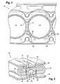
- la figure 1 est une vue de dessus d'un joint de culasse incorporant un canal selon l'invention,
- la figure 2 est une coupe transversale (perpendiculaire au plan du joint) illustrant en détails un canal selon un mode de réalisation,
- la figure 3 est une vue en perspective illustrant la surface d'une feuille du joint dans laquelle est ménagée au moins un canal,
- les figures 4A à 4L sont des coupes transversales illustrant de manière non limitatives différentes variantes de réalisation d'un canal selon l'invention,
- la figure 5 est une coupe transversale illustrant en détails une portion d'un canal réalisé dans une tôle, et
- les figures 6A à 6C sont des coupes illustrant les différentes étapes de réalisation d'un sillon.
- Sur la figure 1, on a représenté en 10 un joint, susceptible d'être intercalé entre des première et seconde surfaces à étancher, par exemple une culasse et un bloc moteur dans le cas d'un joint de culasse.
- Le joint 10 comprend au moins deux feuilles ou plaques métalliques, appelée tôles, revêtues ou non.
- Le joint comprend au moins une ouverture et/ou orifice 12 de manière à faire communiquer des conduits débouchant respectivement au niveau de chaque surface à étancher. Dans le cas d'un joint de culasse, le joint comprend au moins une ouverture susceptible de coopérer avec une chambre de combustion et des orifices permettant le passage de fluides ou des moyens de serrage tels que des tiges filetées.
- De manière connue, le joint comprend au moins une barrière d'étanchéité, de préférence dynamique, sous forme d'une nervure 14, la distance séparant les deux surfaces à étancher étant susceptible de varier en fonctionnement.
- Selon les cas, la nervure 14 s'étend de manière continue ou non, de manière circulaire ou non. A titre d'exemple, la nervure 14 peut entourer une ouverture 12 prévue pour une chambre de combustion. Dans ce cas, la nervure peut être sensiblement circulaire et être disposée à une distance sensiblement constante du bord du joint délimitant l'ouverture 12.
- La présente invention se rapporte plus précisément au joint comprenant au moins une tôle dite active 16 sur laquelle est ménagée au moins une nervure 14 et un support 18 disposé contre la tôle active, sur lequel sont susceptibles d'être rapportées ou ménagées des surépaisseurs afin de limiter les déformations de ladite au moins une nervure pour qu'elle conserve ses propriétés élastiques. De préférence, le joint comprend deux tôles actives disposées de part et d'autre du support, lesdites tôles actives ayant des formes symétriques par rapport au support 18.
- Les tôles actives et le support ont généralement des contours sensiblement identiques.
- Pour fixer un ordre de grandeur, le support a une épaisseur de l'ordre de 0,6 mm. Pour obtenir l'effet élastique au niveau de la ou des nervure(s), les tôles actives sont réalisées à partir d'un acier ayant une résistance à la traction Rm élevée, notamment supérieure à 1000 MPa.
- La tôle active n'est pas plus détaillée car elle peut avoir différentes formes en fonction des caractéristiques recherchées.
- Même si l'invention est décrite appliquée à un joint de culasse, elle n'est aucunement limitée à cette application et couvre différents type de joints, les matériaux utilisés ainsi que les formes et les dimensions pouvant varier.
- En fonctionnement, on note que les zones du joint disposées au droit des lignes d'étanchéité, notamment des nervures 14, sont soumises à des efforts de pression importants.
- Selon l'invention, le joint comprend au moins un canal 20 ménagé dans l'épaisseur du support 18, ledit support étant composé de deux éléments 22 et 24 sous forme de tôles accolées l'une contre l'autre, au moins un sillon 26 s'étendant sur la longueur du canal 20 étant ménagé au niveau d'au moins une des surfaces en contact des deux éléments 22, 24 formant le support 18.
- Par sillon, on entend une forme en creux réalisée au niveau d'une surface qui peut être rectiligne et/ou courbe.
- Selon une caractéristique importante de l'invention, le sillon 26 est obtenu par déformation plastique de la matière, notamment par estampage et non par emboutissage, cette déformation plastique n'engendrant des déformations qu'au niveau d'une seule des surfaces des tôles accolées. L'autre surface ne subit aucune déformation et reste sensiblement plane, si bien que la présence du canal n'engendre aucune perturbation pour la fonction d'étanchéité du joint.
- Cette solution permet également d'obtenir un procédé industrialisable et des coûts de production compatibles avec les produits du marché.
- Selon un mode de réalisation préféré, les tôles formant le support sont réalisées à partir d'un métal ayant des caractéristiques de malléabilité importantes et non un coefficient d'élasticité élevé comme pour les tôles actives.
- A titre d'exemple, les tôles accolées 22 et 24 formant le support sont réalisées à partir d'un acier dont la nuance est choisi parmi les aciers pas ou faiblement alliés, les aciers dits « carbone » par exemple.
- Le fait de déformer la tôle par estampage permet d'obtenir un refoulement de la matière autour du sillon 26, et notamment au niveau des bords latéraux. Ce refoulement de la matière engendre une modification de la structure métallique, et notamment une réduction de la taille des grains autour du sillon comme schématisé sur la figure 5. Cette modification de structure permet d'obtenir une plus grande dureté et résistance à la compression ce qui permet de limiter les risques de constriction du canal.
- Selon une autre caractéristique importante de l'invention, les éléments accolés 22, 24 dans lesquels est ménagé au moins un sillon 26 comprennent à proximité dudit sillon au moins un évidement 28 vers lequel peut fluer la matière lors de la déformation plastique. Cette caractéristique permet de limiter le risque de déformation de la tôle, au niveau de laquelle est réalisé le sillon, qui reste sensiblement plane et sans perturber la fonction d'étanchéité des nervures.
- L'évidement 28 s'étend parallèlement au sillon sur toute la longueur dudit sillon ou partiellement de manière continue ou discontinue.
- Avantageusement, des évidements 28 sont réalisés de part et d'autre du sillon comme illustré sur la figure 6C.
- De préférence, les sections des évidements 28 ont des surfaces sensiblement identiques à celle du sillon 26 afin que la matière chassée du sillon vienne se loger dans les rainures.
- Avantageusement, les évidements 28 traversent la tôle 22 ou 24 au niveau de laquelle ils sont ménagés. Cette solution est plus simple à réaliser et permet d'éviter le galbe de la tôle.
- La position, les formes et les dimensions des évidements 28 sont adaptées de manière à ce que lors de la formation du sillon, la matière chassée flue en direction dudit évidement et n'engendre aucune déformation sur la surface extérieure du support.
- Ainsi, selon l'invention, il est possible de réaliser un canal 20 dans le plan du joint. Les éléments 22, 24 constituant le support 18 ont des surfaces extérieures, en contact avec les tôles actives ou les éléments à étancher, non déformées et sensiblement planes afin de ne pas nuire au fonctionnement des nervures. De plus, les surfaces extérieures du support étant sensiblement planes, le canal n'est pas soumis à une concentration d'efforts de compression susceptible d'engendrer sa constriction.
- Ainsi, les canaux peuvent traverser les lignes d'étanchéité sans risque de constriction du canal et de nuisance des fonctions d'étanchéité.
- Selon les variantes, le canal 20 peut être borgne, débouchant seulement à une de ses extrémités ou à chacune de ses extrémités. De plus, le joint peut comprendre un ou plusieurs canaux indépendants ou reliés de manière à former un réseau de canaux.
- Selon les cas, le canal peut déboucher au niveau du chant du joint, en périphérie du support 18 ou déboucher au niveau d'une des surfaces du support 18.
- A titre d'exemple, lorsque le canal est utilisé pour faire communiquer deux conduits non alignés des éléments à étancher en contact avec le joint, ce dernier comprend un canal 20 qui s'étend entre les deux conduits à relier, ménagé dans le support, chacune des extrémités du canal 20 débouchant au niveau d'une des surfaces du support, au droit du conduit correspondant, un orifice étant ménagé dans les tôles actives de manière à faire communiquer les conduits des éléments avec le canal du joint.
- Comme illustré sur la figure 1, le canal 20 (dessiné à droite) peut relier deux conduits prévus pour acheminer un liquide de refroidissement et traverser la zone prévue entre deux ouvertures susceptibles de coopérer avec les chambres de combustion. Cette solution permet d'obtenir un refroidissement de zones difficilement accessibles.
- Selon une autre application du canal, ce dernier peut être utilisé pour loger des fils lorsque le joint est instrumenté. Dans ce cas, le canal peut avoir une première extrémité non débouchante se terminant sous forme d'une cavité dans laquelle est susceptible de se loger un capteur, une sonde ou analogue et une seconde extrémité débouchante en périphérie du joint.
- Selon les variantes, les deux éléments accolés 22 et 24 formant le support comprennent au niveau des surfaces en contact des sillons 26, un sur chaque surface en contact, disposés en vis à vis de manière à former le canal 20, comme illustré sur les figures 2, 4A, 4C, 4E, 4H, 41, 4J.
- Selon d'autres variantes illustrées sur les figures 4B, 4D, 4F, 4G, 4K, un seul des éléments accolés 22 ou 24 formant le support 18 comprend au niveau de sa surface en contact un sillon 26, l'autre étant sensiblement plan au droit dudit évidement de manière à le refermer pour former un canal.
- De manière à obtenir un procédé industrialisable, les éléments accolés 22 et 24 sont des plaques accolées l'une contre l'autre.
- Elles sont solidarisées par tous moyens appropriés. Selon l'invention, elles peuvent être reliées par soudage comme illustré sur les figures 4C, 4G, par des éléments rajoutés comme des rivets ou oeillets comme illustré sur la figure 4L, par des formes complémentaires entre les deux plaques notamment des bords recourbés ménagés au niveau d'une des plaques susceptibles d'enserrer l'autre plaque comme illustré sur les figures 2, 4A, 4B, 4D, par déformation plastique simultanée des deux plaques, notamment poinçonnage, comme illustré sur la figure 4E, par collage ou autre.
- Selon les variantes, les plaques accolées 22 et 24 peuvent avoir des épaisseurs sensiblement identiques, notamment lorsque les sillons 26 sont ménagés dans les deux plaques, comme illustré sur les figures 2, 4A, 4C, 4E, 4H, 4I, 4J, 4L.
- Selon d'autres variantes, l'une des deux plaques peut se présenter sous la forme d'une fine plaque recouvrant le sillon ménagé dans l'autre plaque plus épaisse, comme illustré sur les figures 4B, 4D, 4F, 4G, 4K.
- Selon les variantes, la nervure ou les nervures assurant l'étanchéité au niveau des tôles actives peuvent être complètes et avoir un profil en forme de créneau évasé, comme illustré sur les figures 4A à 4G ou être sous la forme de demi-nervures comme illustré sur les figures 4H à 4L.
- Selon un mode de réalisation, les sillons 26 ont une section transversale sous forme de demi cercle. Ainsi, le canal 20 peut avoir une section transversale circulaire lorsque les sillons 26 sont ménagés dans les deux plaques accolées 24 et 26 comme illustré sur les figures 2, 4A, 4C, 4E, 4H, 4I, 4J, 4L ou avoir une section transversale en forme de demi cercle lorsqu'un sillon 26 est ménagé au niveau seulement d'une plaque accolée comme illustré sur les figures 4B, 4b, 4F, 4G, 4K.
- Sur les figures 4A à 4L, les évidements 28 sont représentés de manière schématique par un simple trait.
- Cependant, les sillons et les canaux peuvent avoir d'autres formes de section.
- Pour limiter les risques de constriction du canal, ce dernier sera de préférence sécant avec les lignes d'étanchéité. Ainsi, les portions du canal parallèles à une ligne d'étanchéité seront limitées.
- Sur les figures 6A à 6C, on a représenté les différentes étapes de réalisation du sillon. Préalablement, comme illustré sur la figure 1, la plaque accolée 22 ou 24 a une épaisseur sensiblement constante, les faces 30, 30' étant sensiblement planes. En suivant, au moins un évidement 28 est réalisé à proximité de la position théorique du sillon 26 à réaliser, comme illustré sur la figure 6B. Enfin, le sillon est réalisé par déformation plastique, notamment par estampage. Lors de cette déformation, la matière flue vers les évidements 28 ce qui limite les déformations au niveau de la surface 30'.
- Selon l'invention, la profondeur du sillon peut représenter 80% de l'épaisseur de la plaque 22, 24 dans laquelle il est réalisé. A titre d'exemple, pour un support de 0,6mm d'épaisseur, on peut réaliser un canal ayant un diamètre de l'ordre de 0,48 mm.
Claims (10)
- Procédé de réalisation d'un canal dans le plan d'un joint multi feuilles comportant au moins une tôle dite active (16) sur laquelle est ménagée au moins une nervure (14) et un support (18) disposé contre la tôle active, caractérisé en ce qu'il consiste à réaliser le support à partir de deux éléments (22, 24) accolés, à former au moins un évidement (28) à proximité du canal à réaliser et à créer par déformation plastique un sillon (26) s'étendant sur la longueur du canal, ménagé au niveau d'au moins une des surfaces en contact des deux éléments accolés formant le support, la position, les formes et/ou les dimensions dudit au moins un évidement (28) étant adaptées pour permettre à la matière chassée du sillon de fluer vers ledit évidement (28).
- Procédé de réalisation d'un canal dans le plan d'un joint multi feuilles selon la revendication 1, caractérisé en ce qu'il consiste à réaliser un sillon (26) sur chaque surface en contact des deux éléments accolés (24, 26) formant le support (18).
- Procédé de réalisation d'un canal dans le plan d'un joint multi feuilles selon la revendication 1, caractérisé en ce qu'il consiste à réaliser un sillon (26) sur une surface en contact d'un seul élément accolé (24, 26) formant le support.
- Procédé de réalisation d'un canal dans un plan d'un joint multi feuilles selon l'une quelconque des revendications précédentes, caractérisé en ce qu'il consiste à réaliser le support à partir de deux tôles accolées et solidarisées par tous moyens, la ou les tôles dans lesquelles est réalisé ledit au moins un sillon (26) étant en acier ayant des caractéristiques de malléabilité importantes.
- Joint multi feuilles comportant au moins une tôle dite active (16) sur laquelle est ménagée au moins une nervure (14) et un support (18) disposé contre la tôle active, caractérisé en ce qu'il comprend deux éléments accolés (22, 24) formant le support (18), au moins un sillon (26) obtenu par déformation plastique ménagé au niveau d'au moins une des surfaces en contact desdits deux éléments accolés (22, 24), ledit sillon formant un canal lorsque lesdits éléments (22, 24) sont accolées l'un contre l'autre et au moins un évidement (28) à proximité du canal, la position, les formes et/ou les dimensions dudit au moins un évidement (28) étant adaptées pour permettre à la matière chassée du sillon de fluer vers ledit évidement (28).
- Joint multi feuilles selon la revendication 5, caractérisé en ce qu'il comprend un sillon (26) sur chaque surface en contact des deux éléments accolés (24, 26) formant le support (18).
- Joint multi feuilles selon la revendication 5, caractérisé en ce qu'il comprend un sillon (26) sur une surface en contact d'un seul élément accolé (24, 26) formant le support.
- Joint multi feuilles selon l'une quelconque des revendications 5 à 7, caractérisé en ce que le support (18) comprend deux tôles métalliques accolées et solidarisées par tous moyens, et en ce que la structure métallique est modifiée autour du sillon obtenu par une déformation plastique.
- Joint multi feuilles selon l'une quelconque des revendications 5 à 8, caractérisé en ce que le support comprend deux tôles accolées (22, 24) en acier ayant des caractéristiques de malléabilité importantes.
- Joint multi feuilles selon l'une quelconque des revendications 5 à 9, caractérisé en ce qu'il comprend un canal (20) reliant des orifices susceptibles de coopérer avec des conduits prévus pour acheminer un liquide de refroidissement et traversant une zone prévue entre deux ouvertures susceptibles de coopérer avec les chambres de combustion.
Applications Claiming Priority (1)
| Application Number | Priority Date | Filing Date | Title |
|---|---|---|---|
| FR0652836A FR2903473B1 (fr) | 2006-07-06 | 2006-07-06 | Joint multifeuilles incorporant au moins un canal |
Publications (2)
| Publication Number | Publication Date |
|---|---|
| EP1876377A1 true EP1876377A1 (fr) | 2008-01-09 |
| EP1876377B1 EP1876377B1 (fr) | 2014-06-25 |
Family
ID=37781939
Family Applications (1)
| Application Number | Title | Priority Date | Filing Date |
|---|---|---|---|
| EP20070012550 Not-in-force EP1876377B1 (fr) | 2006-07-06 | 2007-06-27 | Joint multifeuilles incorporant au moins un canal |
Country Status (2)
| Country | Link |
|---|---|
| EP (1) | EP1876377B1 (fr) |
| FR (1) | FR2903473B1 (fr) |
Citations (2)
| Publication number | Priority date | Publication date | Assignee | Title |
|---|---|---|---|---|
| WO2003071119A2 (fr) * | 2002-02-15 | 2003-08-28 | Dana Corporation | Dispositif de detection de pression destine a mesurer des pressions associees a des conditions de cognement dans des cylindres de moteur |
| US20060096362A1 (en) * | 2004-11-08 | 2006-05-11 | Federal-Mogul World Wide, Inc. | Cylinder head gasket with integrated sensor |
-
2006
- 2006-07-06 FR FR0652836A patent/FR2903473B1/fr not_active Expired - Fee Related
-
2007
- 2007-06-27 EP EP20070012550 patent/EP1876377B1/fr not_active Not-in-force
Patent Citations (2)
| Publication number | Priority date | Publication date | Assignee | Title |
|---|---|---|---|---|
| WO2003071119A2 (fr) * | 2002-02-15 | 2003-08-28 | Dana Corporation | Dispositif de detection de pression destine a mesurer des pressions associees a des conditions de cognement dans des cylindres de moteur |
| US20060096362A1 (en) * | 2004-11-08 | 2006-05-11 | Federal-Mogul World Wide, Inc. | Cylinder head gasket with integrated sensor |
Also Published As
| Publication number | Publication date |
|---|---|
| FR2903473B1 (fr) | 2008-09-12 |
| EP1876377B1 (fr) | 2014-06-25 |
| FR2903473A1 (fr) | 2008-01-11 |
Similar Documents
| Publication | Publication Date | Title |
|---|---|---|
| EP1637780B1 (fr) | Joint comprenant au moins une nervure incorporant un limiteur d'écrasement | |
| WO2000022339A1 (fr) | Assemblage filete integral de deux tubes metalliques | |
| EP2935759B1 (fr) | Procede de controle d'un etat de vissage d'un joint filete tubulaire | |
| FR2918726A1 (fr) | Accouplement d'arbres par engrenage a denture droite. | |
| FR2855439A1 (fr) | Procede de fabrication d'une aube creuse pour turbomachine. | |
| EP2886804B1 (fr) | Dispositif d'étanchéité pour un compresseur de turbomachine | |
| EP2683966B1 (fr) | Joint semi-ondulé | |
| EP1876377B1 (fr) | Joint multifeuilles incorporant au moins un canal | |
| EP1693606A1 (fr) | Joint métallique comportant une surépaisseur formée de protubérances discontinues | |
| EP2202431B1 (fr) | Joint de bloc moteur, notamment pour le montage d'un composant faiblement rigide sur ledit bloc moteur | |
| EP1430241B1 (fr) | Joint de culasse comprenant un stoppeur bord a bord lie par agrafage | |
| EP1748232B1 (fr) | Joint pour puits de bougie | |
| EP1536166B1 (fr) | Joint comprenant une tôle avec une surépaisseur | |
| EP1409898A1 (fr) | Joint de culasse comprenant un stoppeur bord a bord | |
| FR2916828A1 (fr) | Raccord 3 voies hydroforme. | |
| EP2202432A1 (fr) | Joint d'etanchéité | |
| EP1409897B1 (fr) | Joint de culasse comprenant un stoppeur bord a bord | |
| EP1693605B1 (fr) | Joint métallique comportant une surépaisseur formée par au moins une nervure en lacets | |
| FR3002867A1 (fr) | Outil pour former une collerette a une extremite d'un tube | |
| FR2863514A1 (fr) | Procede d'obtention d'une surepaisseur au niveau d'une tole et joint comprenant ladite tole | |
| EP3313669B1 (fr) | Instrument d'écriture a pointe a usage multiple | |
| EP1555466B1 (fr) | Procédé d'obtention d'une surépaisseur sur une tôle et joint d'étanchéité incorporant ladite tôle | |
| FR2827639A1 (fr) | Joint de culasse comprenant un stoppeur bord a bord | |
| FR2827637A1 (fr) | Joint de culasse comprenant un stoppeur bord a bord | |
| EP1133654A1 (fr) | Dispositif de raccordement d'une conduite metallique |
Legal Events
| Date | Code | Title | Description |
|---|---|---|---|
| PUAI | Public reference made under article 153(3) epc to a published international application that has entered the european phase |
Free format text: ORIGINAL CODE: 0009012 |
|
| 17P | Request for examination filed |
Effective date: 20071116 |
|
| AK | Designated contracting states |
Kind code of ref document: A1 Designated state(s): AT BE BG CH CY CZ DE DK EE ES FI FR GB GR HU IE IS IT LI LT LU LV MC MT NL PL PT RO SE SI SK TR |
|
| AX | Request for extension of the european patent |
Extension state: AL BA HR MK YU |
|
| AKX | Designation fees paid |
Designated state(s): AT BE BG CH CY CZ DE DK EE ES FI FR GB GR HU IE IS IT LI LT LU LV MC MT NL PL PT RO SE SI SK TR |
|
| RAP1 | Party data changed (applicant data changed or rights of an application transferred) |
Owner name: ELRINGKLINGER AG |
|
| GRAP | Despatch of communication of intention to grant a patent |
Free format text: ORIGINAL CODE: EPIDOSNIGR1 |
|
| INTG | Intention to grant announced |
Effective date: 20140117 |
|
| GRAS | Grant fee paid |
Free format text: ORIGINAL CODE: EPIDOSNIGR3 |
|
| GRAA | (expected) grant |
Free format text: ORIGINAL CODE: 0009210 |
|
| AK | Designated contracting states |
Kind code of ref document: B1 Designated state(s): AT BE BG CH CY CZ DE DK EE ES FI FR GB GR HU IE IS IT LI LT LU LV MC MT NL PL PT RO SE SI SK TR |
|
| REG | Reference to a national code |
Ref country code: GB Ref legal event code: FG4D Free format text: NOT ENGLISH |
|
| REG | Reference to a national code |
Ref country code: CH Ref legal event code: EP |
|
| REG | Reference to a national code |
Ref country code: AT Ref legal event code: REF Ref document number: 674926 Country of ref document: AT Kind code of ref document: T Effective date: 20140715 |
|
| REG | Reference to a national code |
Ref country code: IE Ref legal event code: FG4D Free format text: LANGUAGE OF EP DOCUMENT: FRENCH |
|
| REG | Reference to a national code |
Ref country code: DE Ref legal event code: R096 Ref document number: 602007037292 Country of ref document: DE Effective date: 20140807 |
|
| PG25 | Lapsed in a contracting state [announced via postgrant information from national office to epo] |
Ref country code: FI Free format text: LAPSE BECAUSE OF FAILURE TO SUBMIT A TRANSLATION OF THE DESCRIPTION OR TO PAY THE FEE WITHIN THE PRESCRIBED TIME-LIMIT Effective date: 20140625 Ref country code: LT Free format text: LAPSE BECAUSE OF FAILURE TO SUBMIT A TRANSLATION OF THE DESCRIPTION OR TO PAY THE FEE WITHIN THE PRESCRIBED TIME-LIMIT Effective date: 20140625 Ref country code: CY Free format text: LAPSE BECAUSE OF FAILURE TO SUBMIT A TRANSLATION OF THE DESCRIPTION OR TO PAY THE FEE WITHIN THE PRESCRIBED TIME-LIMIT Effective date: 20140625 Ref country code: GR Free format text: LAPSE BECAUSE OF FAILURE TO SUBMIT A TRANSLATION OF THE DESCRIPTION OR TO PAY THE FEE WITHIN THE PRESCRIBED TIME-LIMIT Effective date: 20140926 |
|
| REG | Reference to a national code |
Ref country code: AT Ref legal event code: MK05 Ref document number: 674926 Country of ref document: AT Kind code of ref document: T Effective date: 20140625 |
|
| REG | Reference to a national code |
Ref country code: NL Ref legal event code: VDEP Effective date: 20140625 |
|
| REG | Reference to a national code |
Ref country code: LT Ref legal event code: MG4D |
|
| PG25 | Lapsed in a contracting state [announced via postgrant information from national office to epo] |
Ref country code: LV Free format text: LAPSE BECAUSE OF FAILURE TO SUBMIT A TRANSLATION OF THE DESCRIPTION OR TO PAY THE FEE WITHIN THE PRESCRIBED TIME-LIMIT Effective date: 20140625 Ref country code: SE Free format text: LAPSE BECAUSE OF FAILURE TO SUBMIT A TRANSLATION OF THE DESCRIPTION OR TO PAY THE FEE WITHIN THE PRESCRIBED TIME-LIMIT Effective date: 20140625 |
|
| PG25 | Lapsed in a contracting state [announced via postgrant information from national office to epo] |
Ref country code: CZ Free format text: LAPSE BECAUSE OF FAILURE TO SUBMIT A TRANSLATION OF THE DESCRIPTION OR TO PAY THE FEE WITHIN THE PRESCRIBED TIME-LIMIT Effective date: 20140625 Ref country code: RO Free format text: LAPSE BECAUSE OF FAILURE TO SUBMIT A TRANSLATION OF THE DESCRIPTION OR TO PAY THE FEE WITHIN THE PRESCRIBED TIME-LIMIT Effective date: 20140625 Ref country code: ES Free format text: LAPSE BECAUSE OF FAILURE TO SUBMIT A TRANSLATION OF THE DESCRIPTION OR TO PAY THE FEE WITHIN THE PRESCRIBED TIME-LIMIT Effective date: 20140625 Ref country code: SK Free format text: LAPSE BECAUSE OF FAILURE TO SUBMIT A TRANSLATION OF THE DESCRIPTION OR TO PAY THE FEE WITHIN THE PRESCRIBED TIME-LIMIT Effective date: 20140625 Ref country code: EE Free format text: LAPSE BECAUSE OF FAILURE TO SUBMIT A TRANSLATION OF THE DESCRIPTION OR TO PAY THE FEE WITHIN THE PRESCRIBED TIME-LIMIT Effective date: 20140625 Ref country code: PT Free format text: LAPSE BECAUSE OF FAILURE TO SUBMIT A TRANSLATION OF THE DESCRIPTION OR TO PAY THE FEE WITHIN THE PRESCRIBED TIME-LIMIT Effective date: 20141027 |
|
| REG | Reference to a national code |
Ref country code: CH Ref legal event code: PL |
|
| PG25 | Lapsed in a contracting state [announced via postgrant information from national office to epo] |
Ref country code: NL Free format text: LAPSE BECAUSE OF FAILURE TO SUBMIT A TRANSLATION OF THE DESCRIPTION OR TO PAY THE FEE WITHIN THE PRESCRIBED TIME-LIMIT Effective date: 20140625 Ref country code: AT Free format text: LAPSE BECAUSE OF FAILURE TO SUBMIT A TRANSLATION OF THE DESCRIPTION OR TO PAY THE FEE WITHIN THE PRESCRIBED TIME-LIMIT Effective date: 20140625 Ref country code: IS Free format text: LAPSE BECAUSE OF FAILURE TO SUBMIT A TRANSLATION OF THE DESCRIPTION OR TO PAY THE FEE WITHIN THE PRESCRIBED TIME-LIMIT Effective date: 20141025 Ref country code: PL Free format text: LAPSE BECAUSE OF FAILURE TO SUBMIT A TRANSLATION OF THE DESCRIPTION OR TO PAY THE FEE WITHIN THE PRESCRIBED TIME-LIMIT Effective date: 20140625 |
|
| REG | Reference to a national code |
Ref country code: IE Ref legal event code: MM4A |
|
| REG | Reference to a national code |
Ref country code: DE Ref legal event code: R097 Ref document number: 602007037292 Country of ref document: DE |
|
| PG25 | Lapsed in a contracting state [announced via postgrant information from national office to epo] |
Ref country code: MC Free format text: LAPSE BECAUSE OF FAILURE TO SUBMIT A TRANSLATION OF THE DESCRIPTION OR TO PAY THE FEE WITHIN THE PRESCRIBED TIME-LIMIT Effective date: 20140625 |
|
| PG25 | Lapsed in a contracting state [announced via postgrant information from national office to epo] |
Ref country code: LI Free format text: LAPSE BECAUSE OF NON-PAYMENT OF DUE FEES Effective date: 20140630 Ref country code: IT Free format text: LAPSE BECAUSE OF FAILURE TO SUBMIT A TRANSLATION OF THE DESCRIPTION OR TO PAY THE FEE WITHIN THE PRESCRIBED TIME-LIMIT Effective date: 20140625 Ref country code: IE Free format text: LAPSE BECAUSE OF NON-PAYMENT OF DUE FEES Effective date: 20140627 Ref country code: DK Free format text: LAPSE BECAUSE OF FAILURE TO SUBMIT A TRANSLATION OF THE DESCRIPTION OR TO PAY THE FEE WITHIN THE PRESCRIBED TIME-LIMIT Effective date: 20140625 Ref country code: CH Free format text: LAPSE BECAUSE OF NON-PAYMENT OF DUE FEES Effective date: 20140630 |
|
| PLBE | No opposition filed within time limit |
Free format text: ORIGINAL CODE: 0009261 |
|
| STAA | Information on the status of an ep patent application or granted ep patent |
Free format text: STATUS: NO OPPOSITION FILED WITHIN TIME LIMIT |
|
| GBPC | Gb: european patent ceased through non-payment of renewal fee |
Effective date: 20140925 |
|
| 26N | No opposition filed |
Effective date: 20150326 |
|
| REG | Reference to a national code |
Ref country code: DE Ref legal event code: R082 Ref document number: 602007037292 Country of ref document: DE Representative=s name: HOEGER, STELLRECHT & PARTNER PATENTANWAELTE MB, DE |
|
| PG25 | Lapsed in a contracting state [announced via postgrant information from national office to epo] |
Ref country code: GB Free format text: LAPSE BECAUSE OF NON-PAYMENT OF DUE FEES Effective date: 20140925 |
|
| PG25 | Lapsed in a contracting state [announced via postgrant information from national office to epo] |
Ref country code: SI Free format text: LAPSE BECAUSE OF FAILURE TO SUBMIT A TRANSLATION OF THE DESCRIPTION OR TO PAY THE FEE WITHIN THE PRESCRIBED TIME-LIMIT Effective date: 20140625 |
|
| PG25 | Lapsed in a contracting state [announced via postgrant information from national office to epo] |
Ref country code: MT Free format text: LAPSE BECAUSE OF FAILURE TO SUBMIT A TRANSLATION OF THE DESCRIPTION OR TO PAY THE FEE WITHIN THE PRESCRIBED TIME-LIMIT Effective date: 20140625 |
|
| PG25 | Lapsed in a contracting state [announced via postgrant information from national office to epo] |
Ref country code: BG Free format text: LAPSE BECAUSE OF FAILURE TO SUBMIT A TRANSLATION OF THE DESCRIPTION OR TO PAY THE FEE WITHIN THE PRESCRIBED TIME-LIMIT Effective date: 20140625 |
|
| REG | Reference to a national code |
Ref country code: FR Ref legal event code: PLFP Year of fee payment: 10 |
|
| PG25 | Lapsed in a contracting state [announced via postgrant information from national office to epo] |
Ref country code: HU Free format text: LAPSE BECAUSE OF FAILURE TO SUBMIT A TRANSLATION OF THE DESCRIPTION OR TO PAY THE FEE WITHIN THE PRESCRIBED TIME-LIMIT; INVALID AB INITIO Effective date: 20070627 Ref country code: BE Free format text: LAPSE BECAUSE OF FAILURE TO SUBMIT A TRANSLATION OF THE DESCRIPTION OR TO PAY THE FEE WITHIN THE PRESCRIBED TIME-LIMIT Effective date: 20140630 Ref country code: TR Free format text: LAPSE BECAUSE OF FAILURE TO SUBMIT A TRANSLATION OF THE DESCRIPTION OR TO PAY THE FEE WITHIN THE PRESCRIBED TIME-LIMIT Effective date: 20140625 Ref country code: LU Free format text: LAPSE BECAUSE OF NON-PAYMENT OF DUE FEES Effective date: 20140627 |
|
| PGFP | Annual fee paid to national office [announced via postgrant information from national office to epo] |
Ref country code: FR Payment date: 20160621 Year of fee payment: 10 |
|
| REG | Reference to a national code |
Ref country code: FR Ref legal event code: ST Effective date: 20180228 |
|
| PG25 | Lapsed in a contracting state [announced via postgrant information from national office to epo] |
Ref country code: FR Free format text: LAPSE BECAUSE OF NON-PAYMENT OF DUE FEES Effective date: 20170630 |
|
| REG | Reference to a national code |
Ref country code: DE Ref legal event code: R082 Ref document number: 602007037292 Country of ref document: DE Representative=s name: HOEGER, STELLRECHT & PARTNER PATENTANWAELTE MB, DE |
|
| PGFP | Annual fee paid to national office [announced via postgrant information from national office to epo] |
Ref country code: DE Payment date: 20210621 Year of fee payment: 15 |
|
| REG | Reference to a national code |
Ref country code: DE Ref legal event code: R119 Ref document number: 602007037292 Country of ref document: DE |
|
| PG25 | Lapsed in a contracting state [announced via postgrant information from national office to epo] |
Ref country code: DE Free format text: LAPSE BECAUSE OF NON-PAYMENT OF DUE FEES Effective date: 20230103 |